

Page 1
ISC-1310FB
P1 P2
RS422/
485
FiberRS232
TX-
TX+
TX
RX
RX-
RX+
D-
D+
Quick InstallationGuide
Version 1.0
Quick Installation Guide
Introduction
PRINTED ON RECYCLED PAPER
QIG
ISC-1310FB Series
1907-2-29-ISC1310FB-1.0
The is acost-effective solution forconversion between RS232/422/485 and100Base-FX interfaces, allowing you to extend serial
communication distancesusing optical fiber. The device providesa wide
operating temperature ranging from -40 ~ 70 Cand a widevoltage range
from 12~48VDC power inputs,making it anideal serial mediaconverter
suitable for harsh environments.
ISC-1310FB
o
Package Contents
Installation
The device is shippedwith the followingitems. If anyof these itemsis
missing ordamaged, please contactyour customer servicerepresentative for
assistance.
Preparation
Before installation, makesure you have all of the package contents
available.
Elevated OperatingAmbient:
ReducedAir Flow:
Mechanical Loading:
Circuit Overloading:
If installed in a closed cabinet, theoperating
ambient temperatureof the rackenvironment may begreater than roomambient.
Therefore, considerationshould be givento installing theequipment in an
environment compatiblewith the maximumambient temperature (Tma)specified
by themanufacturer.
Installation of the equipment should be such that the
amount of air flow required for safe operation of the equipment is not
compromised.
Mounting of the equipment in the d should be
such that a hazardous condition is not achieved due to uneven mechanical
loading.
Consideration shouldbe given tothe connection ofthe
equipment tothe supply circuitand the effectthat overloading ofthe circuits
might haveon overcurrent protectionand supply wiring.Appropriate
consideration ofequipment nameplate ratingsshould be used when addressing
this concern.
in-rail
Safety & Warnings
Contents
Wall-mountKit
DIN-rail Kit
ISC-1310FB-MM or
ISC-1310FB-SS
Pictures Number
X2
X1
QIG
X1
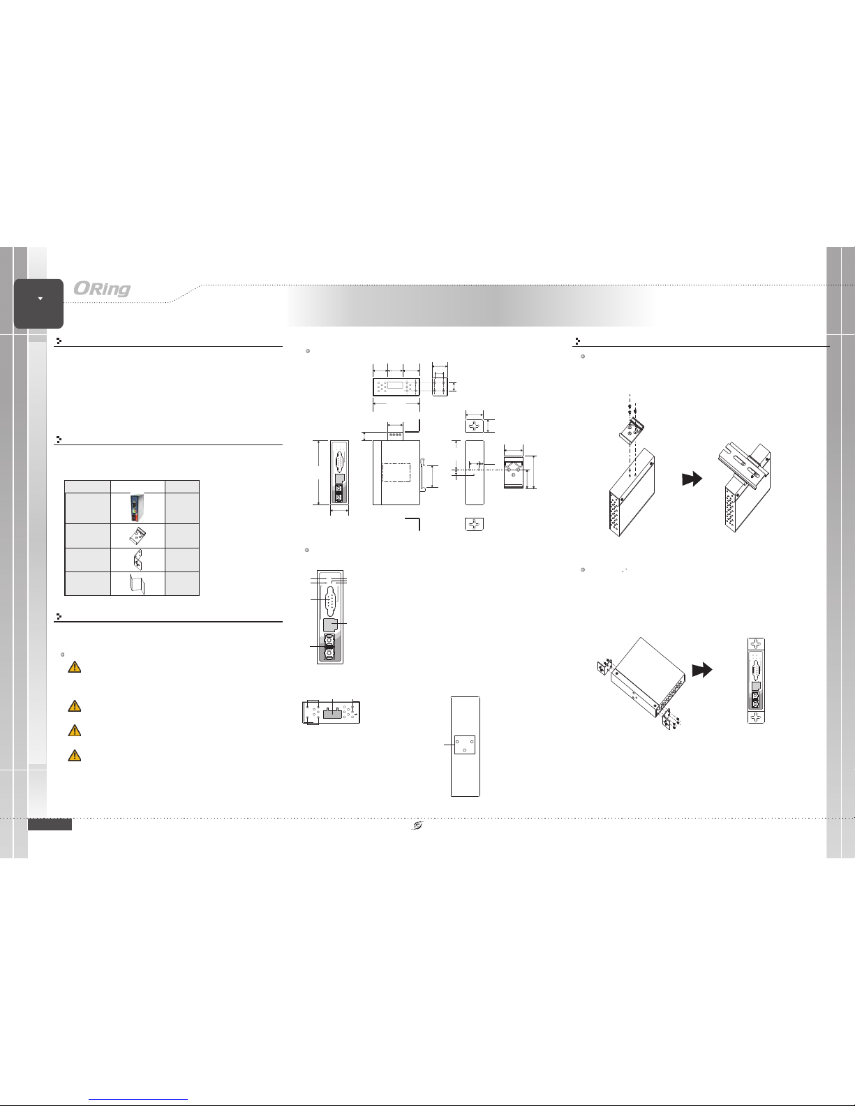
Dimension (Unit: mm)
Panel Layouts
Front Panel
1. LEDfor power 1module
2. LEDfor data transmittingfrom RS-422/RS-485 tofiber
3. LEDfor power 2module
4. LEDfor fiber
5. LEDfor data transmittingfrom RS-232 tofiber
6. RS-232port
7. 4-pinterminal block forRS-422/485 signal transmission
8. Opticalfiber port
ISC-1310FB Series
X1
70.0
20.0
43.5
8.0
14.0
6.05
23.0
50.0
25.3
33.6
12.5
12.3
13.1
22.6
26.1
19.0
26.1
95.0
28.0
20.0
22.0
1
8
TopPanel
G
112 3
1. Wall-mountscrew
holes
2. Terminalblock
3. Frameground
Rear Panel
1
1. Din-railscrew holes
Step 1:
Step 2:
Slant the switch and screw theDin-rail kit ontothe back ofthe switch, right in the
middle of the back panel.
Slide theswitch onto aDIN-rail from theDin-rail kit andmake sure theswitch clicks into
the railfirmly.
DIN-rail Installation
Step 1:
Step 2:
Step 3:
Screw the twopieces of wall-mount kits onto bothsides of the switch. A
total of eightscrews are required, as shown below.
Use the switch,with wall mount plates attached, as a guide to mark the correct
locations of the four screws.
Insert four screwheads through the large parts ofthe keyhole-shaped apertures, and
then slide theswitch downwards. Tighten the fourscrews for added stability.
Wall-mounting
6
Media
Converter
Serial
Industrial Serial Media Converter
3
7
ISC-1310FB
P1 P2
RS422/
485
FiberRS232
TX-
TX+
TX
RX
RX-
RX+
D-
D+
2 5
4
ISC-1310FB
P1 P2
RS422/
485
FiberRS232
TX-
TX+
TX
RX
RX-
RX+
D-
D+
Page 2
QIG
Quick InstallationGuide
PRINTED ON RECYCLED PAPER
Quick Installation Guide
Power inputs
STEP 1:
STEP 2:
The device providesa 12~48VDC power input on a 4-pin
terminal block. Please follow steps below to connect power
cables.
Insert the negative/positive wires into the V-/V+
terminals, respectively.
To keep the DC wires from pulling loose, use a small
flat-blade screwdriver to tighten the wire-clamp screws on the
front of the terminalblock connector.
Version 1.0
QIG
Configurations
After installingthe device and connecting cables, the greenpower LED
should turnon. Please referto the followingtablet for LEDindication.
LED indication table
Specifications
Wiring
PWR2
V2+ V2-
PWR1
V1+ V1-
ORing MediaConverter
Model
ISC-1310FB-MM
Fiber PortNumber
1
Fiber Port
Power
Input power
Power consumption(Typ.)
Dual DCinputs. 12~48VDC on4-pin terminal block
1.8 watts
Physical Characteristic
Enclosure
IP-30
Dimension(WxDxH)
26.1(W) x70(D) x 95(H)mm(1.03x 2.76 x3.74inch.)
Weight (g )
Environmental
-40to85C(-40to185F)
oo
Storage Temperature
Operating Temperature
5% to95% Non-condensingOperating Humidity
Warranty
5years
192 g
-40to70C(-40to158F)
oo
PIN Assignment
ISC-1310FB-SS
Media
Converter
Serial
Industrial Serial Media Converter
Fiber PortSpeed
100Base-FX
Fiber OpticalConnector
SC
Fiber Mode
Multi-mode
TypicalDistance (km)
2Km
Wavelength(nm)
1310 nm
TX Output
>-23.5 dbm
Point-to-point transmission
Full-Duplex
RX sensitivity
-31 dbm
RS-232
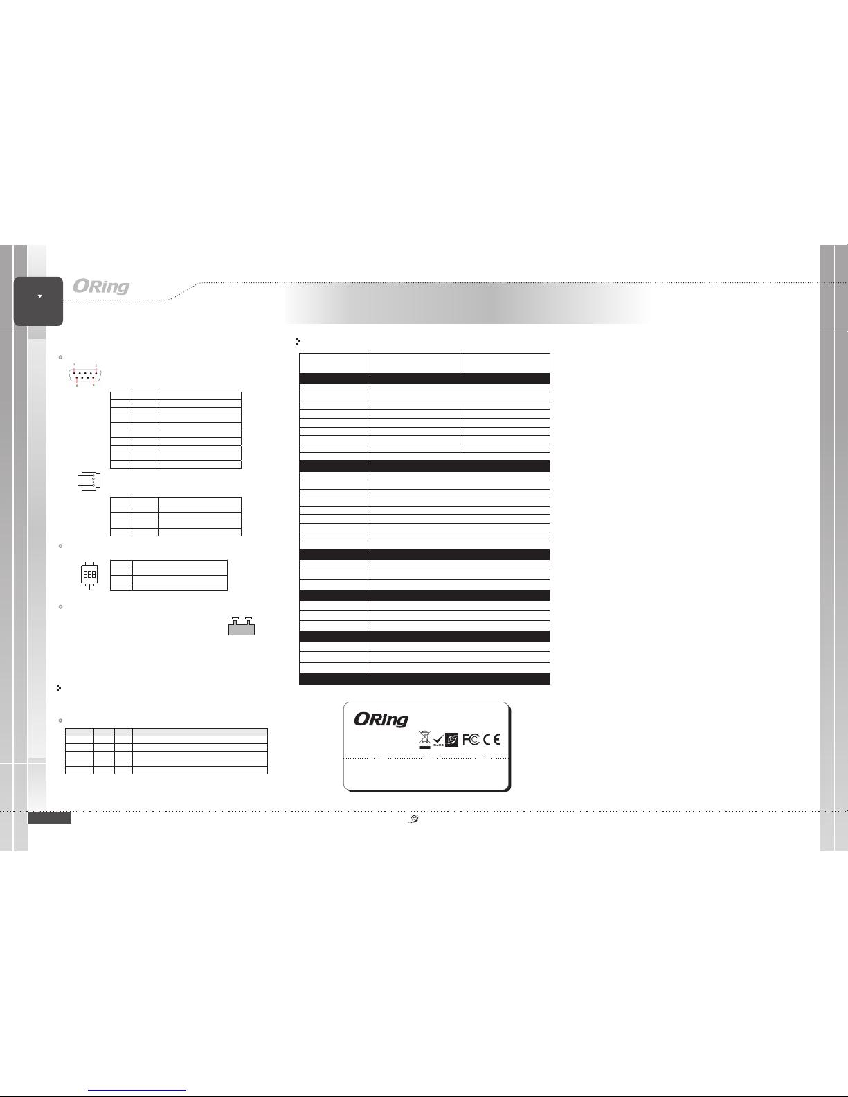
The deviceprovides a RS-232port in DB9connector. Pleaserefer to the
following table for pin assignments.
Pin No. Assignment Description
#1
DCD
Data Carrier Detect
#2
RXD
Receiv e Dat a
#3
TXD Transmit Data
#4
DTR Data Terminal Relay
#5
SG Signal G round
#6
DSR Data Set Rela y
#7
RTS Request Set Rel ay
#8
CTS Clean to Sand
#9
RI Ring Indic ator
RS-422/485
The device provides a 4-pin terminal block for RS-232/422/485 signal
transmission. Please refer to the following table for pin assignments.
Pin No. Assignment Desc ription
#1
Tx+/D+ RS-422/485 Transm ission Line, P ositive
#2
Tx-/D- RS-422/485 Transmission Line, N egative
#3 Rx+ RS-422/ 485 Receiver Lin e, Positive
#4
Rx- RS-422/485 Receive r Line, Nega tive
LED
Color
Status
Description
P1 Green On DCpowermodule1 activated
P2 Green On DCpowermodule1 activated
RS-422/485 G r een On Port is linkedand datatran smittingbetween RS-422/RS-485 andoptical fiber
Fiber Green On Port islinked andexchangingdata
RS-232 Green On Por tis linkedand data transmittingfrom between RS-232and optical fiber
Connector
DB9(male) x1,terminal block x1
Serial Port
RS-232
TxD, RxD, GND
RS-422
TX+, TX-,RX+, RX-,GND
Serial BaudRate
50bpsto921.6Kbps
Data bit
5, 6,7, 8
Stop bit
1, 1.5,2
Operation Mode
RS-232 /RS-422 / 4(2)-WireRS-485.
Parity
None, Even,Odd, Space, Mark
Single-mode
30 Km
1310 nm
>-15 dbm
-34 dbm
RS-485
TX+, TX-,RX+, RX-,GND
Overload currentprotection
Present
ISC-1310FB Series
ISC-1310FB Series
ORing IndustrialNetworking Corp.
Copyright© 2016 ORing
All rightsreserved.
TEL: +886-2-2218-1066
FAX:+886-2-2218-1014
Website: www.oring-networking.com
E-mail: [email protected]
1
4
RS-422
120ohm Term.
DCE
Mode
RS-485 DTE
123
Dip Switch
SW No. Description
#1
RS-422 / RS- 485 mode selec tion
#2
Enable / Disable 120 ohm terminal resistor
#3 RS-232 DTE /DCE switch
 Loading...