

Page 1
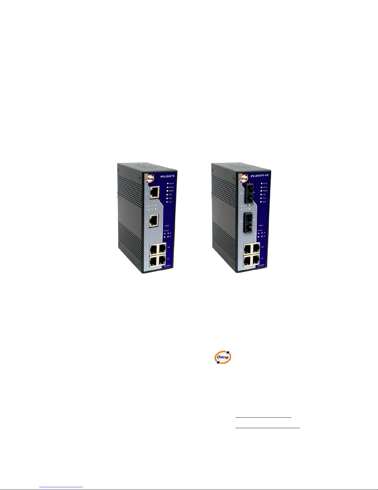
Industrial P.O.E.
Lite-Managed Ethernet Switch
IPS-2042TX / 2042FX Series User’s Manual
Version 1.0
May, 2008.
ORing Industrial Networking Corp.
4F., NO.3, Lane235, Baociao Rd.Sindian City,
Taipei County 23145 Taiwan, R.O.C.
Tel: + 886 2 2918 3036
Fax: + 886 2 2918 3084
Website: www.oring-networking.com
E-mail: [email protected]
Page 2

Table of Content
Getting to Know Your Switch........................................................................3
1.1 About the IPS-2042TX / 2042FX Lite-Managed Industrial Switch ........................... 3
1.2 Software Features .................................................................................................... 3
1.3 Hardware Features................................................................................................... 3
Hardware Installation.....................................................................................4
2.1 Installing Switch on DIN-Rail.................................................................................... 4
2.1.1 Mount IPS-2042TX & IPS-2042FX Series on DIN-Rail ....................................... 4
2.2 Wall Mounting Installation ........................................................................................ 5
2.2.1 Mount IPS-2042TX & IPS-2042FX Series on wall............................................... 5
Hardware Overview........................................................................................7
3.1 Front Panel............................................................................................................... 7
3.2 Front Panel LEDs ................................................................................................... 10
3.3 Bottom Panel.......................................................................................................... 10
3.4 Rear Panel ..............................................................................................................11
Cables...........................................................................................................12
4.1 Ethernet Cables...................................................................................................... 12
4.1.1 100BASE-TX/10BASE-T Pin Assignments........................................................ 12
4.2 Fibers ..................................................................................................................... 13
WEB Management........................................................................................14
5.1 Configuration by Web Browser .............................................................................. 14
5.1.1 About Web-based Management ........................................................................ 14
5.1.2 Basic Setting ...................................................................................................... 15
5.1.2.1 Switch setting ............................................................................................ 15
5.1.2.2 Admin Password ....................................................................................... 16
5.1.2.3 IP configuration ......................................................................................... 17
5.1.2.4 SNTP Configuration .................................................................................. 18
5.1.2.5 Backup & Restore ..................................................................................... 21
5.1.2.6 Upgrade Firmware..................................................................................... 22
5.1.2.7 Factory Default .......................................................................................... 22
5.1.2.8 System Reboot.......................................................................................... 22
ORing Industrial Networking Corp. 1
Page 3

5.1.3 Port Configuration .............................................................................................. 23
5.1.3.1 Port Control ............................................................................................... 23
5.1.3.2 Port Status................................................................................................. 23
5.1.4 Redundancy....................................................................................................... 24
5.1.4.1 Fast Recovery Mode ................................................................................. 24
5.1.4.2 O-Ring ....................................................................................................... 25
5.1.4.3 RSTP......................................................................................................... 26
5.1.5 SNMP Configuration .......................................................................................... 29
5.1.5.1 SNMP – Agent Setting.................................................................................... 29
5.1.5.2 SNMP –Trap Setting ................................................................................. 30
5.1.6 VLAN.................................................................................................................. 31
5.1.6.1 VLAN Configuration – Port Based............................................................. 31
5.1.7 Warning.............................................................................................................. 31
5.1.7.1 Fault Alarm ................................................................................................ 32
5.1.8 Front Panel ........................................................................................................ 35
5.1.9 Save Configuration ............................................................................................ 36
5.1.10 LLDP.............................................................................................................. 36
5.1.11 Power over Ethernet (P.O.E.) ........................................................................ 37
Technical Specifications .............................................................................39
ORing Industrial Networking Corp. 2
Page 4

IPS-2042TX / 2042FX User’s Manual
Getting to Know Your Switch
1.1 About the IPS-2042TX / 2042FX Lite-Managed Industrial
Switch
The IPS-2042TX / 2042FX switch are cost-effect and powerful industrial switch with many
features. These switches can work under wide temperature and dusty environment and
humid condition. IPS-2042TX / 2042FX support Power over Ethernet, a system to transmit
electrical power with data to remote devices over standard twisted-pair cable. Each IPS
series switch has 4 X 10/100TX PSE (Power Sourcing Equipment) ports which are fully
compliant with IEEE 802.3af standard.
The IPS-2042TX / 2042FX switch can be managed by WEB and a useful Window Utility we
called Open-Vision. Open-Vision is powerful network management software. With its
friendly and powerful interface, you can easily configure multiple switches at the same time,
and monitor switches’ status
1.2 Software Features
World’s fastest Redundant Ethernet Ring (Recovery time < 10ms over 250 units
connection)
Supports Ring Coupling, Dual Homing and RSTP over O-Ring
Support fast recovery mode
Easy-to-configure: Web / Windows utility
Windows utility (Open-Vision) for network management
1.3 Hardware Features
Wide Operating Temperature: -40 to 70 oC
Storage Temperature: -40 to 85
o
C
Operating Humidity: 5% to 95%, non-condensing
4 10/100Base-T(X) Ethernet port with PSE provides up to 25 watts
10/100Base-T(X) Ethernet port
100Base-FX Fiber port
ORing Industrial Networking Corp.
3
Page 5
IPS-2042TX / 2042FX User’s Manual
Hardware Installation
2.1 Installing Switch on DIN-Rail
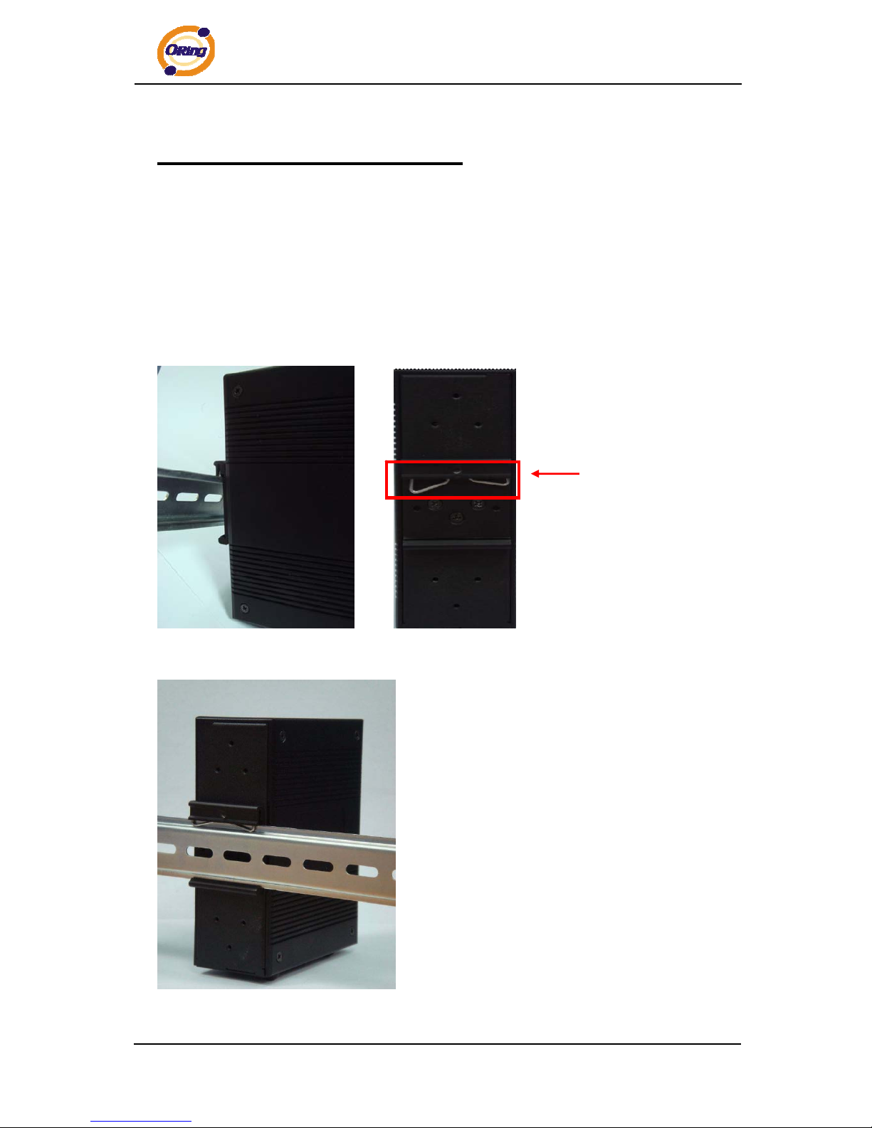
Each switch has a DIN-Rail kit on rear panel. The DIN-Rail kit helps switch to fix on the
DIN-Rail. It is easy to install the switch on the DIN-Rail:
2.1.1
Mount IPS-2042TX & IPS-2042FX Series on DIN-Rail
Step 1: Slant the switch and mount the metal spring to DIN-Rail.
Metal Spring
Step 2: Push the switch toward the DIN-Rail until you heard a “click” sound.
ORing Industrial Networking Corp. 4
Page 6
IPS-2042TX / 2042FX User’s Manual
2.2 Wall Mounting Installation
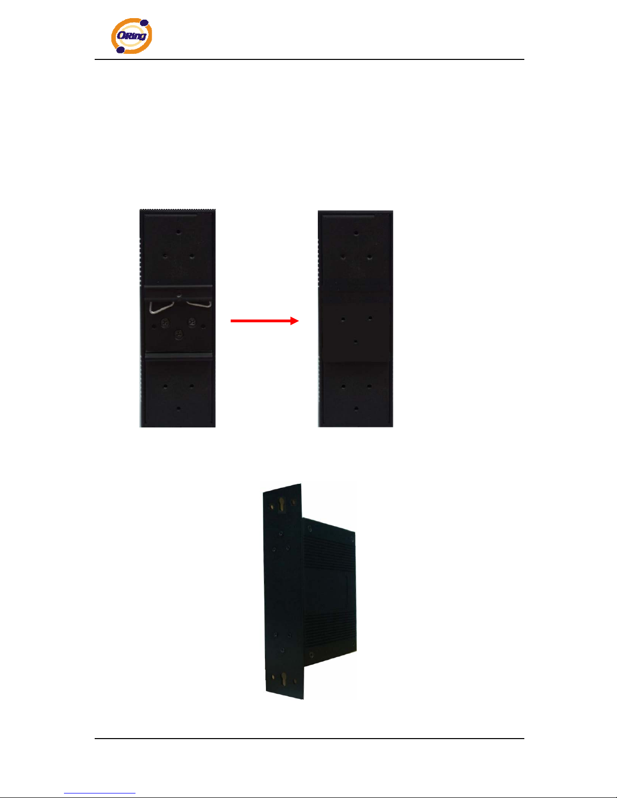
Each switch has another installation method for users to fix the switch. A wall mount panel
can be found in the package. The following steps show how to mount the switch on the
wall:
2.2.1 Mount IPS-2042TX & IPS-2042FX Series on wall
Step 1: Remove DIN-Rail kit.
Step 2: Use 6 screws that can be found in the package to combine the wall mount panel.
Just like the picture shows below:
ORing Industrial Networking Corp.
5
Page 7
IPS-2042TX / 2042FX User’s Manual
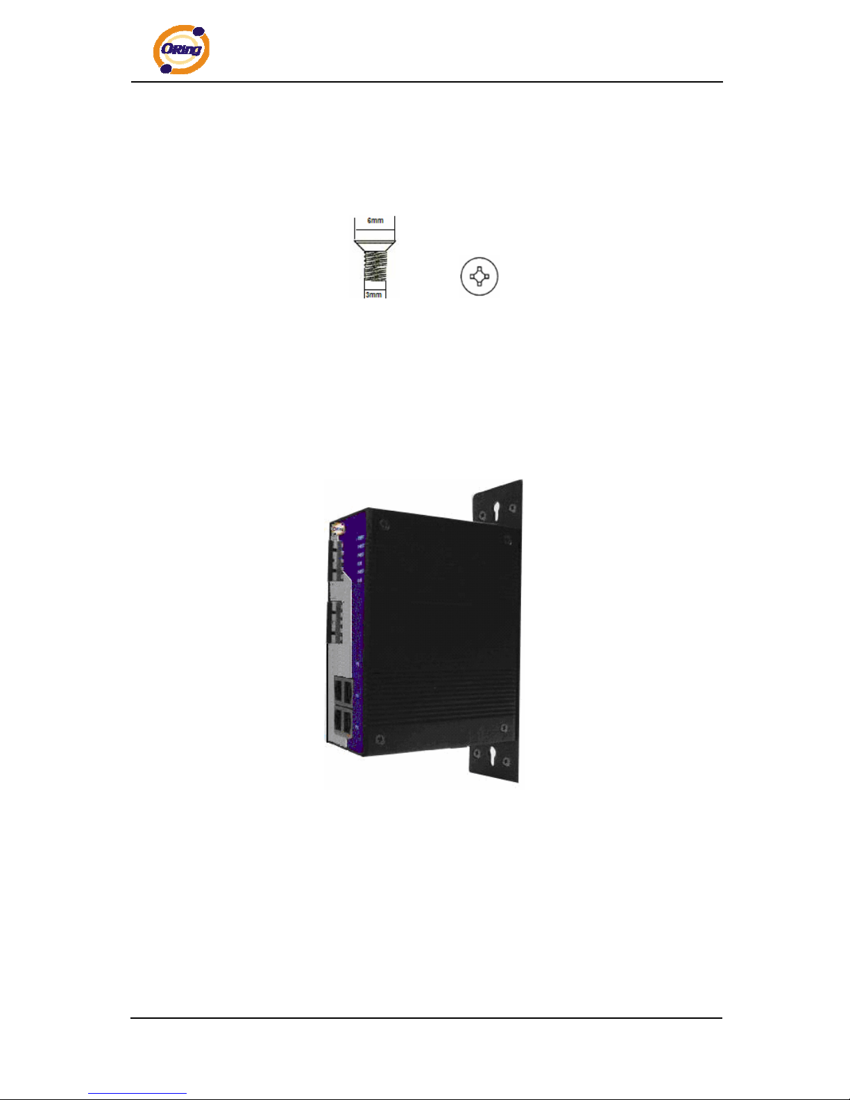
The screws specification shows in the following two pictures. In order to prevent switches
from any damage, the screws should not larger than the size that used in IPS-2042TX /
2042FX.
Pozidrive
Step 3: Mount the combined switch on the wall.
ORing Industrial Networking Corp. 6
Page 8
IPS-2042TX / 2042FX User’s Manual
Hardware Overview
3.1 Front Panel
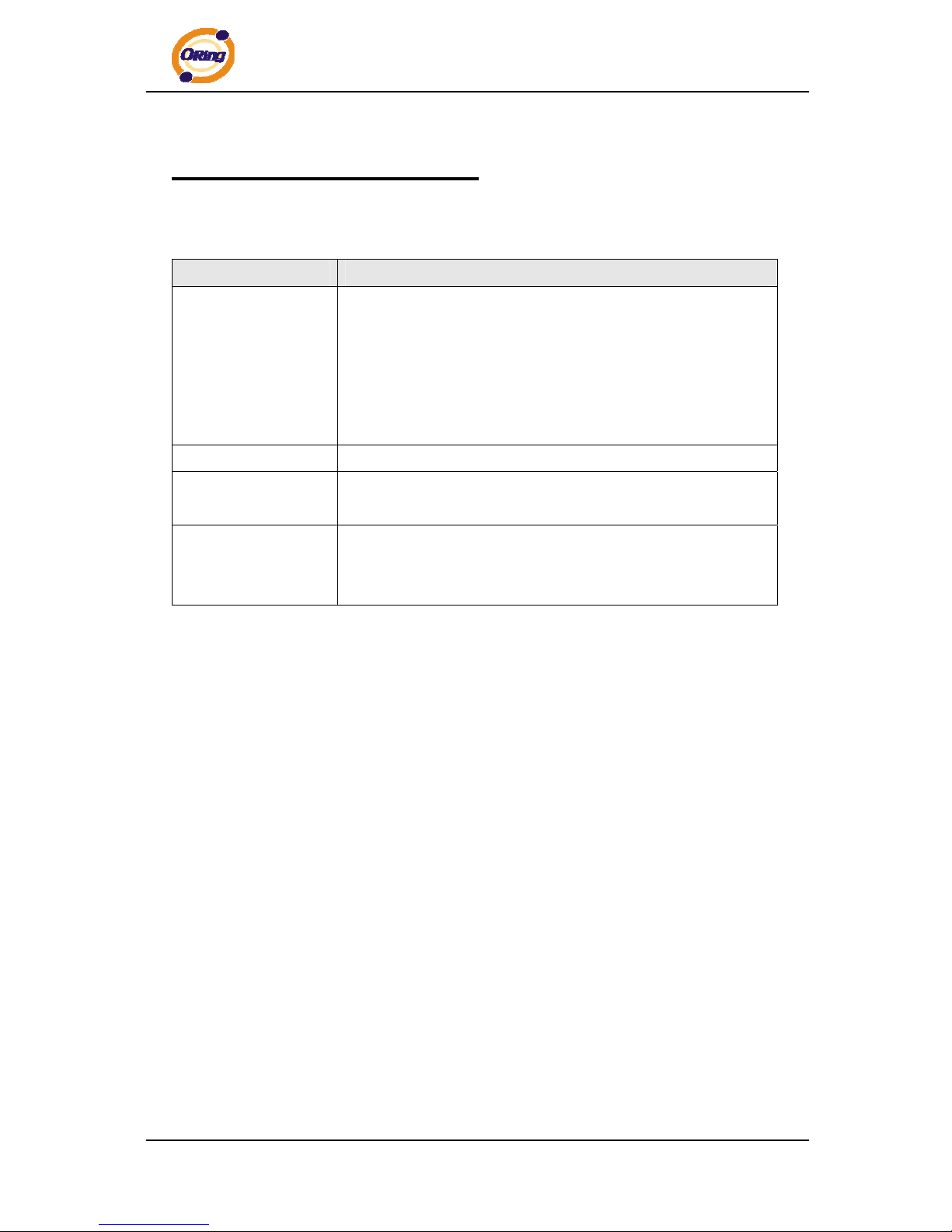
The following table describes the labels that stick on the IPS-2042TX / 2042FX.
Port Description
10/100 RJ-45 fast
Ethernet ports
10/100Base-T(X) RJ-45 fast Ethernet ports support
auto-negotiation.
Default Setting :
Speed: auto
Duplex: auto
Flow control : disable
Fiber port
100BaseFX for IPS-2042FX switch
P.O.E. Port
Port 1 ~ 4 contain PSE function compliant with IEEE802.3af
P.O.E. specifications.
Reset
Push reset button 2 to 3 seconds to reset the switch.
Push reset button 5 second to reset the switch into Factory
Default.
ORing Industrial Networking Corp.
7
Page 9
IPS-2042TX / 2042FX User’s Manual
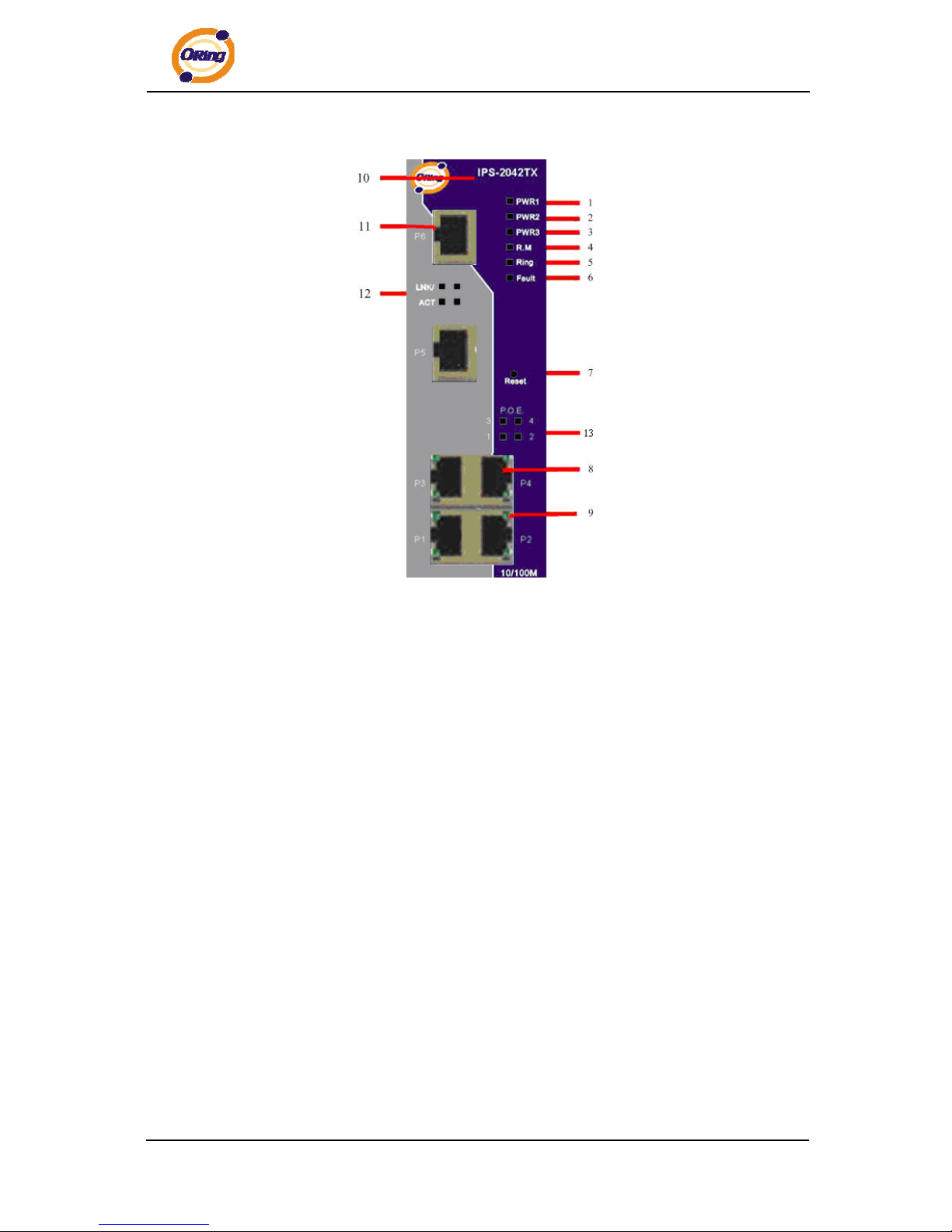
IPS-2042TX
1. LED for PWR1. When the PWR1 links, the green led will be light on.
2. LED for PWR2. When the PWR2 links, the green led will be light on.
3. LED for PWR3. When the PWR3 links, the green led will be light on.
4. LED for R.M (Ring master). When the LED light on, it means that the switch is the ring
master of O-Ring.
5. LED for Ring. When the led light on, it means the O-Ring is activated.
6. LED for Fault Relay. When the fault occurs, the amber LED will be light on.
7. Reset button. Push the button 3 seconds for reset; 5 seconds for factory default.
8. 10/100Base-T(X) Ethernet ports..
9. LED for Ethernet ports status.
10. Model name
11. 10/100Base-T(X) Ethernet ports..
12. LED for Ethernet ports status.
13. LED for P.O.E. power supplied.
ORing Industrial Networking Corp. 8
Page 10
IPS-2042TX / 2042FX User’s Manual
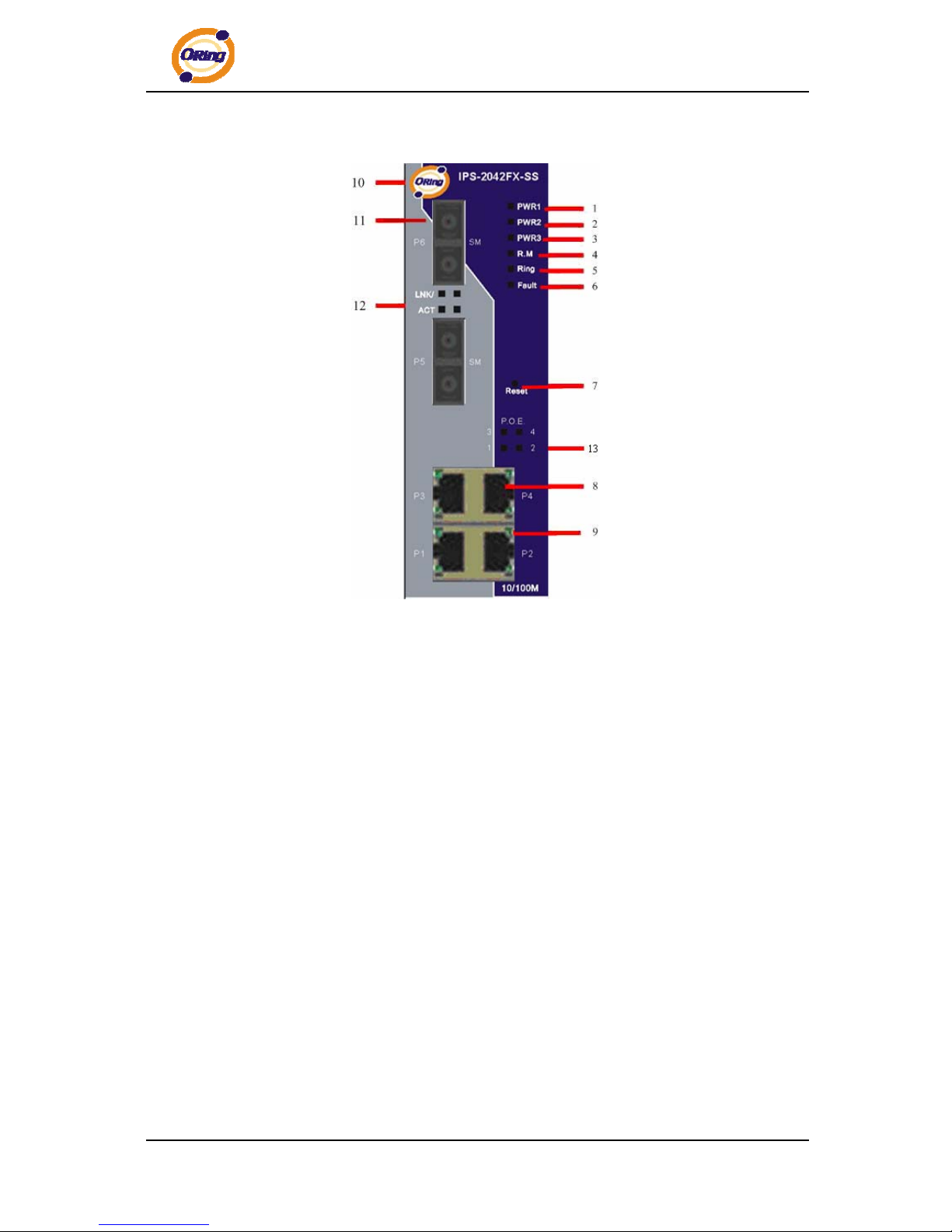
IPS-2042FX Series
1. LED for PWR1. When the PWR1 links, the green led will be light on.
2. LED for PWR2. When the PWR2 links, the green led will be light on.
3. LED for PWR3. When the PWR3 links, the green led will be light on.
4. LED for R.M (Ring master). When the LED light on, it means that the switch is the ring
master of O-Ring.
5. LED for Ring. When the led light on, it means the O-Ring is activated.
6. LED for Fault Relay. When the fault occurs, the amber LED will be light on.
7. Reset button. Push the button 3 seconds for reset; 5 seconds for factory default.
8. 10/100Base-T(X) Ethernet ports.
9. LED for Ethernet ports status.
10. Model name
11. 100BaseFX fiber port.
12. LNK/ACT LED for fiber port.
13. LED for P.O.E. power supplied.
ORing Industrial Networking Corp.
9
Page 11
IPS-2042TX / 2042FX User’s Manual
3.2 Front Panel LEDs
LED Color Status Description
PWR1
Green On DC power module 1 activated.
PWR2
Green On DC power module 2 activated.
PWR3
Green On Power jack activated.
R.M
Green On O-Ring Master.
On O-Ring enabled.
Slowly blinking O-Ring topology has problem
Ring
Green
Fast blinking O-Ring work normally.
Fault
Amber On
Fault relay. Power failure or Port
down/fail.
10/100Base-T(X) Fast Ethernet ports
On Port link up.
LNK / ACT
Green
Blinking Data transmitted.
Full Duplex
Amber On Port works under full duplex.
P.O.E.
Green On P.O.E. activated
100Base-FX Fiber ports
ACT
Green Blinking Data transmitted.
LNK
Amber On Port link up.
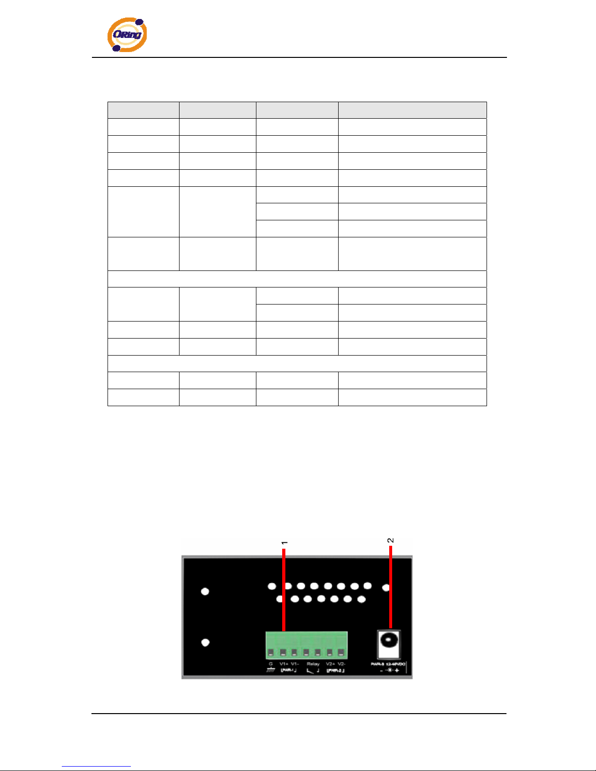
3.3 Bottom Panel
The bottom panel components of IPS-2042TX & IPS-2042FX are showed as below:
1. Terminal block includes: PWR1, PWR2 (+48V DC) and Relay output (1A@24VDC).
2. Power jack for PWR3 (+48VDC).
.
IPS-2042TX / IPS-2042FX power connection
ORing Industrial Networking Corp. 10
Page 12
IPS-2042TX / 2042FX User’s Manual
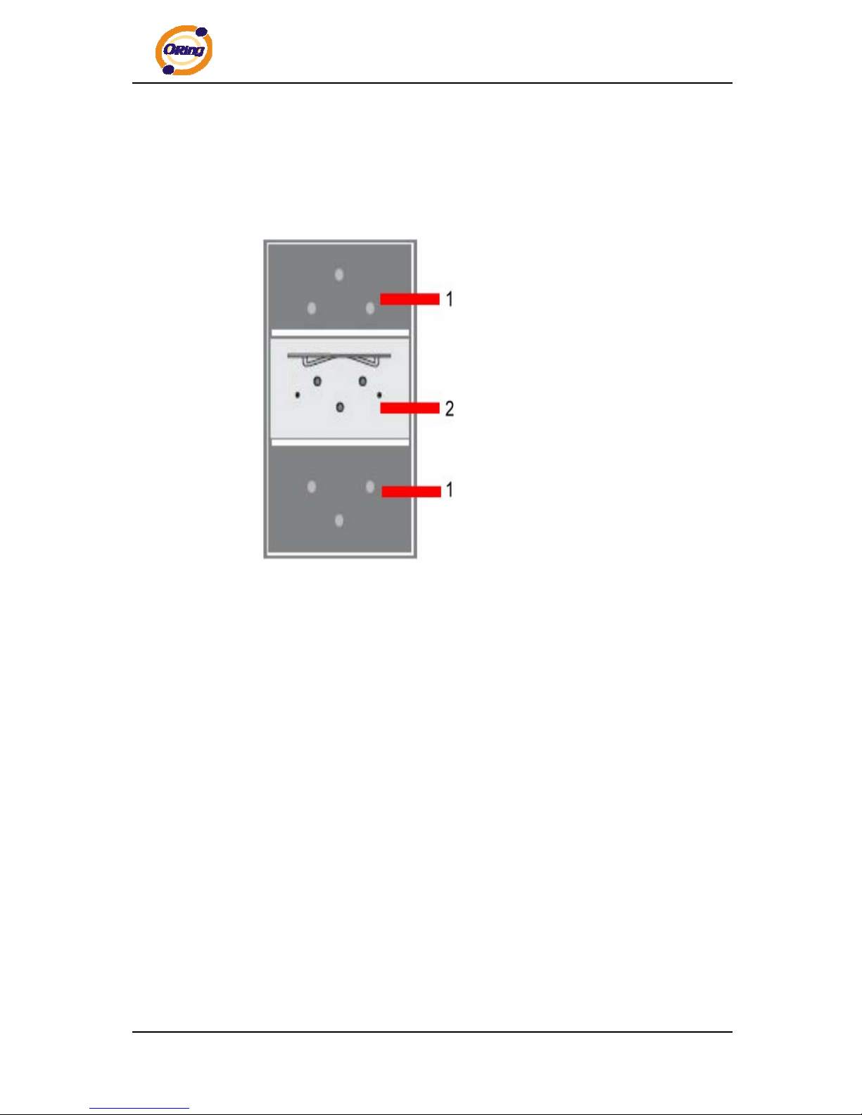
3.4 Rear Panel
The rear panel components of IPS-2042TX / IPS-2042FX are showed as below:
1. Screw holes for wall mount kit.
2. Din-Rail kit
ORing Industrial Networking Corp.
11
Page 13
IPS-2042TX / 2042FX User’s Manual
Cables
4.1 Ethernet Cables
The IPS-2042TX / 2042FX switches have standard Ethernet ports. According to the link
type, the switches use CAT 3, 4, 5,5e UTP cables to connect to any other network device
(PCs, servers, switches, routers, or hubs). Please refer to the following table for cable
specifications.
Cable Types and Specifications
Cable Type Max. Length Connector
10BASE-T Cat. 3, 4, 5 100-ohm UTP 100 m (328 ft) RJ-45
100BASE-TX Cat. 5 100-ohm UTP UTP 100 m (328 ft) RJ-45
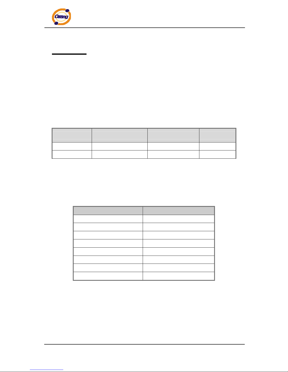
4.1.1 100BASE-TX/10BASE-T Pin Assignments
With 100BASE-TX/10BASE-T cable, pins 1 and 2 are used for transmitting data, and pins
3 and 6 are used for receiving data.
RJ-45 Pin Assignments
Pin Number Assignment
1 TD+
2 TD-
3 RD+
4 P.O.E. power input +
5 P.O.E. power input +
6 RD-
7 P.O.E. power input -
8 P.O.E. power input -
The IPS-2042TX / 2042FX switches support auto MDI/MDI-X operation. You can use a
straight-through cable to connect PC and switch. The following table below shows the
10BASE-T/ 100BASE-TX MDI and MDI-X port pin outs.
ORing Industrial Networking Corp. 12
Page 14
IPS-2042TX / 2042FX User’s Manual
MDI/MDI-X pins assignment
Pin Number MDI port MDI-X port
1 TD+(transmit) RD+(receive)
2 TD-(transmit) RD-(receive)
3 RD+(receive) TD+(transmit)
4 P.O.E. power input + P.O.E. power input +
5 P.O.E. power input + P.O.E. power input +
6 RD-(receive) TD-(transmit)
7 P.O.E. power input - P.O.E. power input -
8 P.O.E. power input - P.O.E. power input -
Note: “+” and “-” signs represent the polarity of the wires that make up each wire pair.
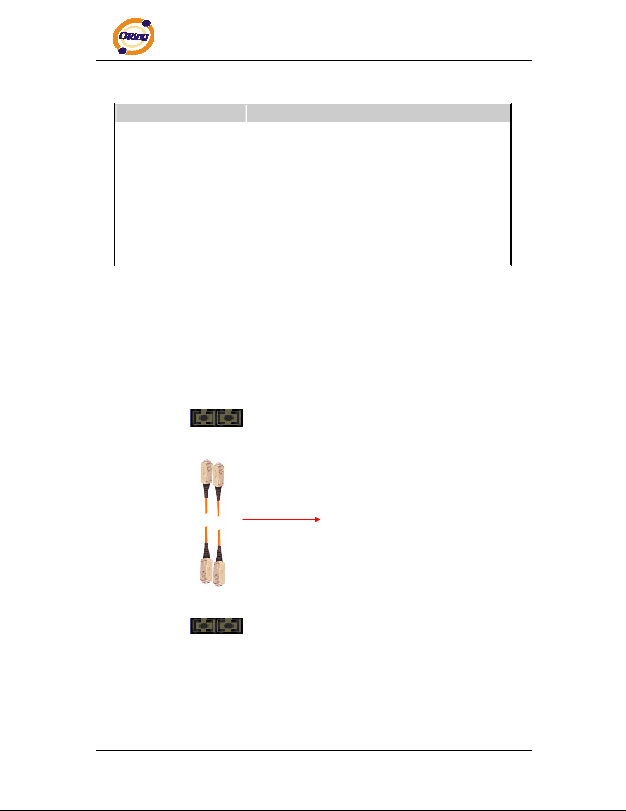
4.2 Fibers
The following two models, IPS-2042FX-MM, IPS-2042FX-SS, have fiber optical ports. The
fiber optical ports are in multi-mode (0 to 2 km, 1310 nm in 50/125 µm, 62.5/125 µm) and
single-mode (9/125 µm) with SC connector. Please remember that the TX port of Switch A
should be connected to the RX port of Switch B.
Switch A
TX RX
Fiber cord
RX TX
Switch B
ORing Industrial Networking Corp.
13
Page 15

IPS-2042TX / 2042FX User’s Manual
WEB Management
5.1 Configuration by Web Browser
This section introduces the configuration by Web browser.
5.1.1 About Web-based Management
An embedded HTML web site resides in flash memory on the CPU board. It contains
advanced management features and allows you to manage the switch from anywhere on
the network through a standard web browser such as Microsoft Internet Explorer.
The Web-Based Management function supports Internet Explorer 5.0 or later. It is based
on Java Applets with an aim to reduce network bandwidth consumption, enhance access
speed and present an easy viewing screen.
Note: By default, IE5.0 or later version does not allow Java Applets to open sockets. You need to explicitly
modify the browser setting in order to enable Java Applets to use network ports.
Preparing for Web Management
The default value is as below:
IP Address: 192.168.10.1
Subnet Mask: 255.255.255.0
Default Gateway: 192.168.10.254
User Name: admin
Password: admin
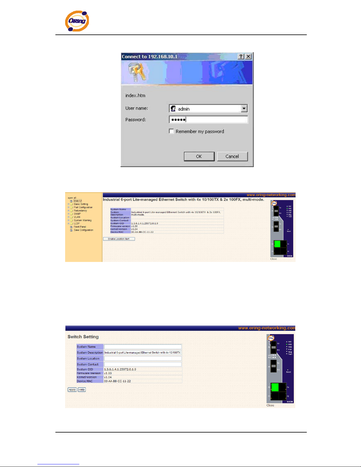
System Login
1. Launch the Internet Explorer.
2. Type http:// and the IP address of the switch. Press “Enter”.
3. The login screen appears.
4. Key in the username and password. The default username and password is
“admin”.
5. Click “Enter” or “OK” button, then the main interface of the Web-based management
appears.
ORing Industrial Networking Corp. 14
Page 16
IPS-2042TX / 2042FX User’s Manual
Login screen
Main Interface
Main interface
5.1.2 Basic Setting
5.1.2.1 Switch setting
Switch setting interface
ORing Industrial Networking Corp.
15
Page 17
IPS-2042TX / 2042FX User’s Manual
The following table describes the labels in this screen.
Label Description
System Name
Assign the name of switch. The maximum length is 64 bytes
System Description
Display the description of switch.
System Location
Assign the switch physical location. The maximum length is 64
bytes
System Contact
Enter the name of contact person or organization
Firmware Version
Display the switch’s firmware version
Kernel Version
Display the kernel software version
MAC Address
Display the unique hardware address assigned by manufacturer
(default)
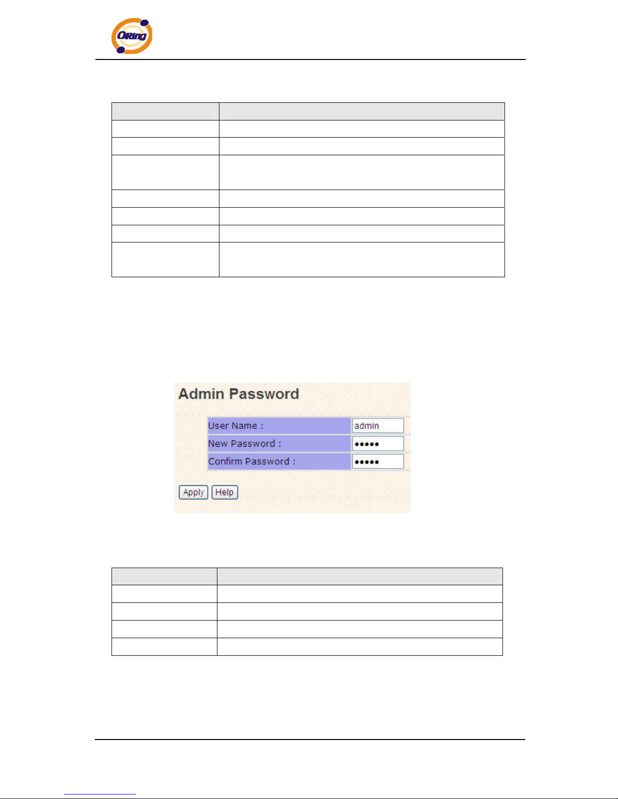
5.1.2.2 Admin Password
Change web management login username and password for the management security
issue
Admin Password interface
The following table describes the labels in this screen.
Label Description
User name
Key in the new username (The default is “admin”)
New Password
Key in the new password (The default is “admin”)
Confirm password
Re-type the new password.
Apply
Click “Apply” to activate the configurations.
ORing Industrial Networking Corp. 16
Page 18
IPS-2042TX / 2042FX User’s Manual
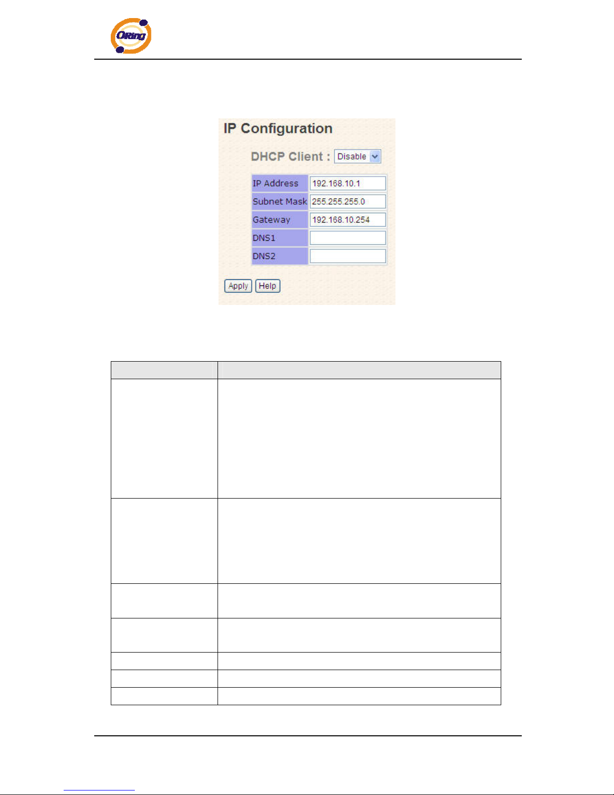
5.1.2.3 IP configuration
You can configure the IP Settings and DHCP client function through IP configuration.
IP Configuration interface
The following table describes the labels in this screen.
Label Description
DHCP Client
To enable or disable the DHCP client function. When DHCP
client function is enabling, the switch will assign the IP address
from the network DHCP server. The default IP address will be
replaced by the IP address which the DHCP server has assigned.
After clicking “Apply” button, a popup dialog will show up to
inform you when the DHCP client is enabling. The current IP will
lose and you should find the new IP on the DHCP server.
IP Address
Assign the IP address that the network is using. If DHCP client
function is enabling, you do not need to assign the IP address.
The network DHCP server will assign the IP address for the
switch and it will be displayed in this column. The default IP is
192.168.10.1
Subnet Mask
Assign the subnet mask for the IP address. If DHCP client
function is enabling, you do not need to assign the subnet mask.
Gateway
Assign the network gateway for the switch. The default gateway
is 192.168.10.254
DNS1
Assign the primary DNS IP address
DNS2
Assign the secondary DNS IP address
Apply
Click “Apply” to activate the configurations.
ORing Industrial Networking Corp.
17
Page 19
IPS-2042TX / 2042FX User’s Manual
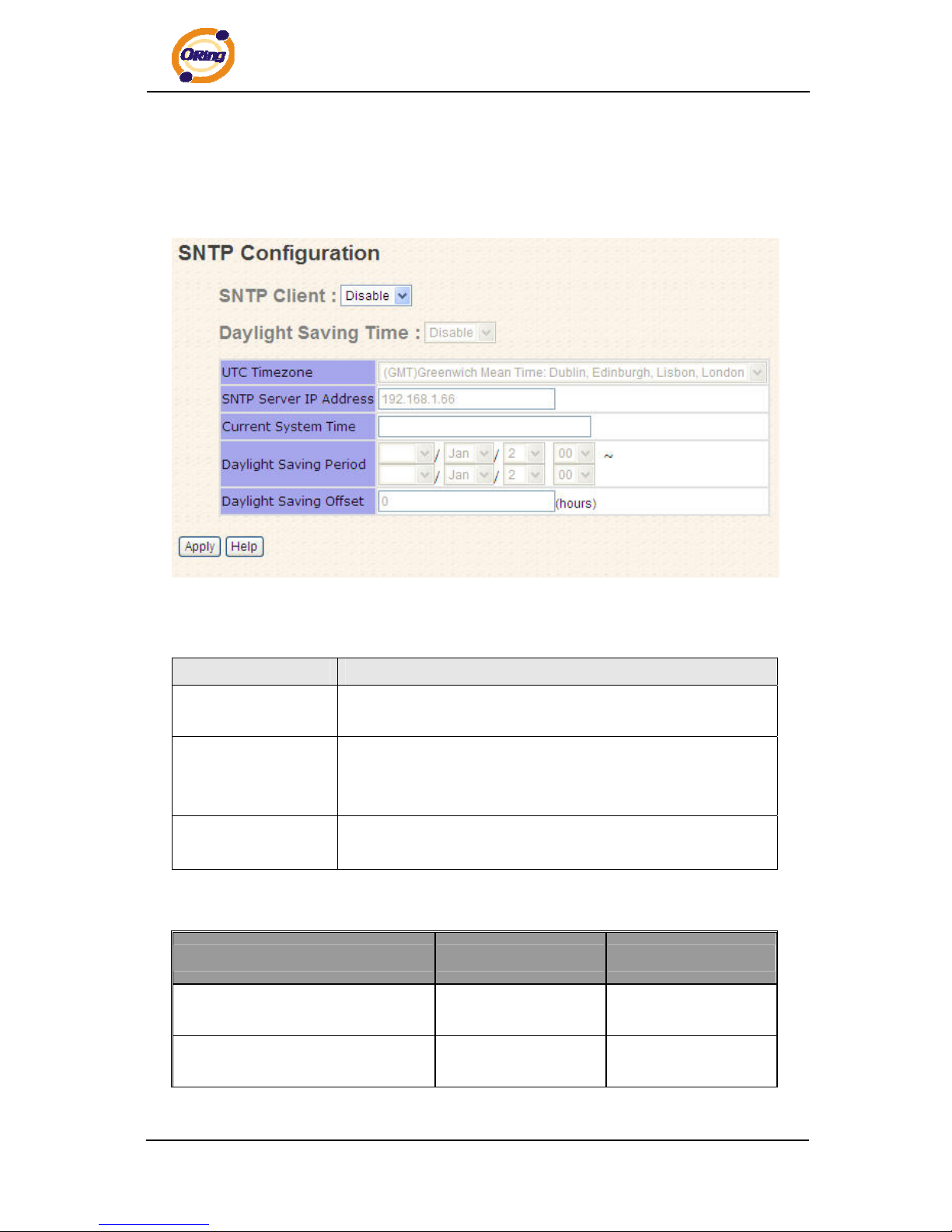
5.1.2.4 SNTP Configuration
The SNTP (Simple Network Time Protocol) settings allow you to synchronize switch
clocks in the Internet.
SNTP Configuration interface
The following table describes the labels in this screen.
Label Description
SNTP Client
Enable or disable SNTP function to get the time from the SNTP
server.
Daylight Saving Time
Enable or disable daylight saving time function. When daylight
saving time is enabling, you need to configure the daylight saving
time period.
UTC Time zone
Set the switch location time zone. The following table lists the
different location time zone for your reference.
Local Time Zone Conversion from UTC Time at 12:00 UTC
November Time Zone - 1 hour 11 am
Oscar Time Zone -2 hours 10 am
ORing Industrial Networking Corp. 18
Page 20

IPS-2042TX / 2042FX User’s Manual
ADT - Atlantic Daylight -3 hours 9 am
AST - Atlantic Standard
EDT - Eastern Daylight
-4 hours 8 am
EST - Eastern Standard
CDT - Central Daylight
-5 hours 7 am
CST - Central Standard
MDT - Mountain Daylight
-6 hours 6 am
MST - Mountain Standard
PDT - Pacific Daylight
-7 hours 5 am
PST - Pacific Standard
ADT - Alaskan Daylight
-8 hours 4 am
ALA - Alaskan Standard -9 hours 3 am
HAW - Hawaiian Standard -10 hours 2 am
Nome, Alaska -11 hours 1 am
CET - Central European
FWT - French Winter
MET - Middle European
MEWT - Middle European Winter
SWT - Swedish Winter
+1 hour 1 pm
EET - Eastern European, USSR
Zone 1
+2 hours 2 pm
BT - Baghdad, USSR Zone 2 +3 hours 3 pm
ZP4 - USSR Zone 3 +4 hours 4 pm
ZP5 - USSR Zone 4 +5 hours 5 pm
ZP6 - USSR Zone 5 +6 hours 6 pm
WAST - West Australian Standard +7 hours 7 pm
CCT - China Coast, USSR Zone 7 +8 hours 8 pm
JST - Japan Standard, USSR Zone 8 +9 hours 9 pm
EAST - East Australian Standard +10 hours 10 pm
ORing Industrial Networking Corp.
19
Page 21
IPS-2042TX / 2042FX User’s Manual
GST
Guam Standard, USSR Zone 9
IDLE - International Date Line
NZST - New Zealand Standard
NZT - New Zealand
+12 hours Midnight
The following table describes the labels in this screen.
Label Description
SNTP Sever IP
Address
Set the SNTP server IP address.
Daylight Saving
Period
Set up the Daylight Saving beginning time and Daylight Saving
ending time. Both will be different each year.
Daylight Saving
Offset
Set up the offset time.
Switch Timer
Display the switch current time.
Apply
Click “Apply” to activate the configurations.
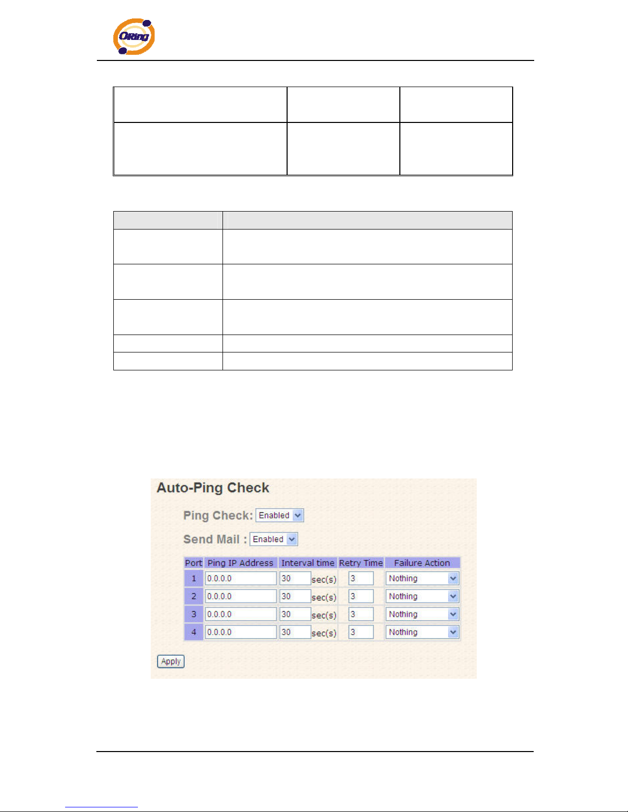
5.1.2.5 Auto-Ping Check
you can control the POE function by using the ping command , in order to turn on or off
other POE device which connect with port assign.
ORing Industrial Networking Corp. 20
Page 22
IPS-2042TX / 2042FX User’s Manual
The following table describes the labels in this screen.
Label Description
Ping Check
Enable or disable Ping Check function
Send Mail
When " ping " fails,can notify users by mail
Port
You can appoint to want to control P.O.E port number
Ping IP Address
Set up ip Address
Interval Time
Spacing interval to set up Ping
Retry Time
Set up the number of times of ping
Failure Action
Set up movements wanted to carry out
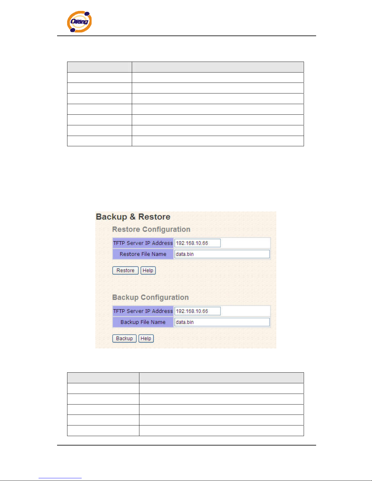
5.1.2.6 Backup & Restore
You can save current EEPROM value of the switch to TFTP server, then go to the TFTP
restore configuration page to restore the EEPROM value.
Backup & Restore interface
The following table describes the labels in this screen.
Label Description
TFTP Server IP Address
Fill in the TFTP server IP
Restore File Name
Fill the file name.
Restore
Click “restore” to restore the configurations.
Restore File Name
Fill the file name.
Restore
Click “restore” to restore the configurations.
ORing Industrial Networking Corp.
21
Page 23
IPS-2042TX / 2042FX User’s Manual
Backup
Click “backup” to backup the configurations.
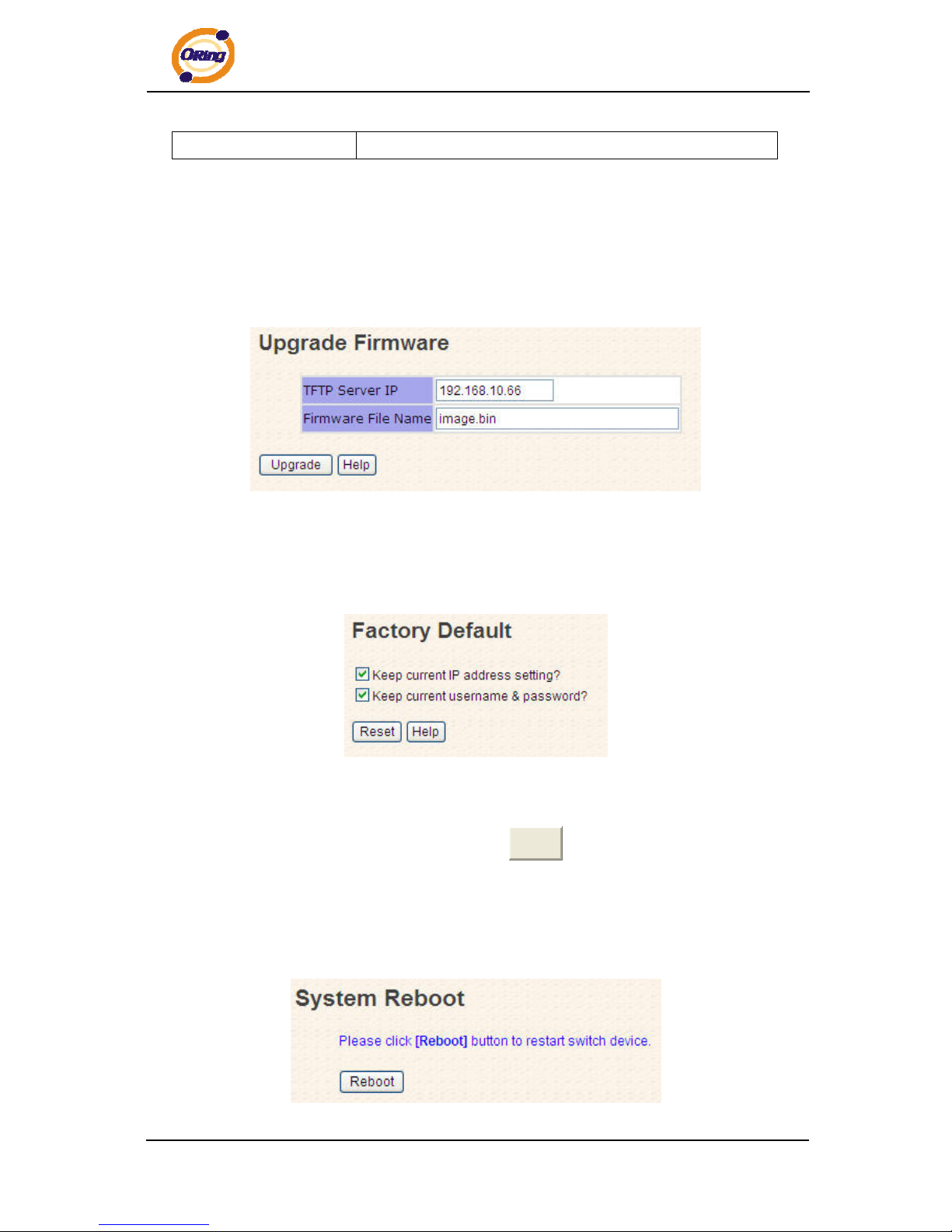
5.1.2.7 Upgrade Firmware
Upgrade Firmware allows you to update the switch firmware. Before updating, make
sure you have your TFTP server ready and the firmware image is on the TFTP server.
Update Firmware interface
5.1.2.8 Factory Default
Factory Default interface
Reset switch to default configuration. Click
Reset
to reset all configurations to the
default value. You can select “
Keep current IP address setting
” and “
Keep current
username & password
” to prevent IP and username & password from default.
5.1.2.9 System Reboot
ORing Industrial Networking Corp. 22
Page 24
IPS-2042TX / 2042FX User’s Manual
System Reboot interface
5.1.3 Port Configuration
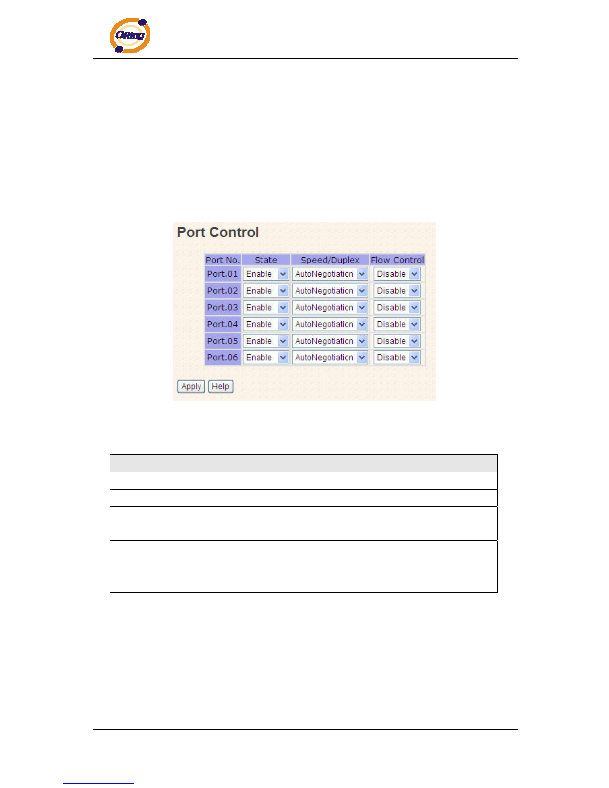
5.1.3.1 Port Control
By this function, you can set the state, speed/duplex, flow control, and security of the
port.
Port Control interface
The following table describes the labels in this screen.
Label Description
Port NO.
Port number for setting.
State
Enable/Disable the port.
Speed/Duplex
You can set Auto-negotiation, 100 full,100 half,10 full,10 half
mode.
Flow Control
Support symmetric and asymmetric mode to avoid packet loss
when congestion occurred.
Apply
Click “Apply” to activate the configurations.
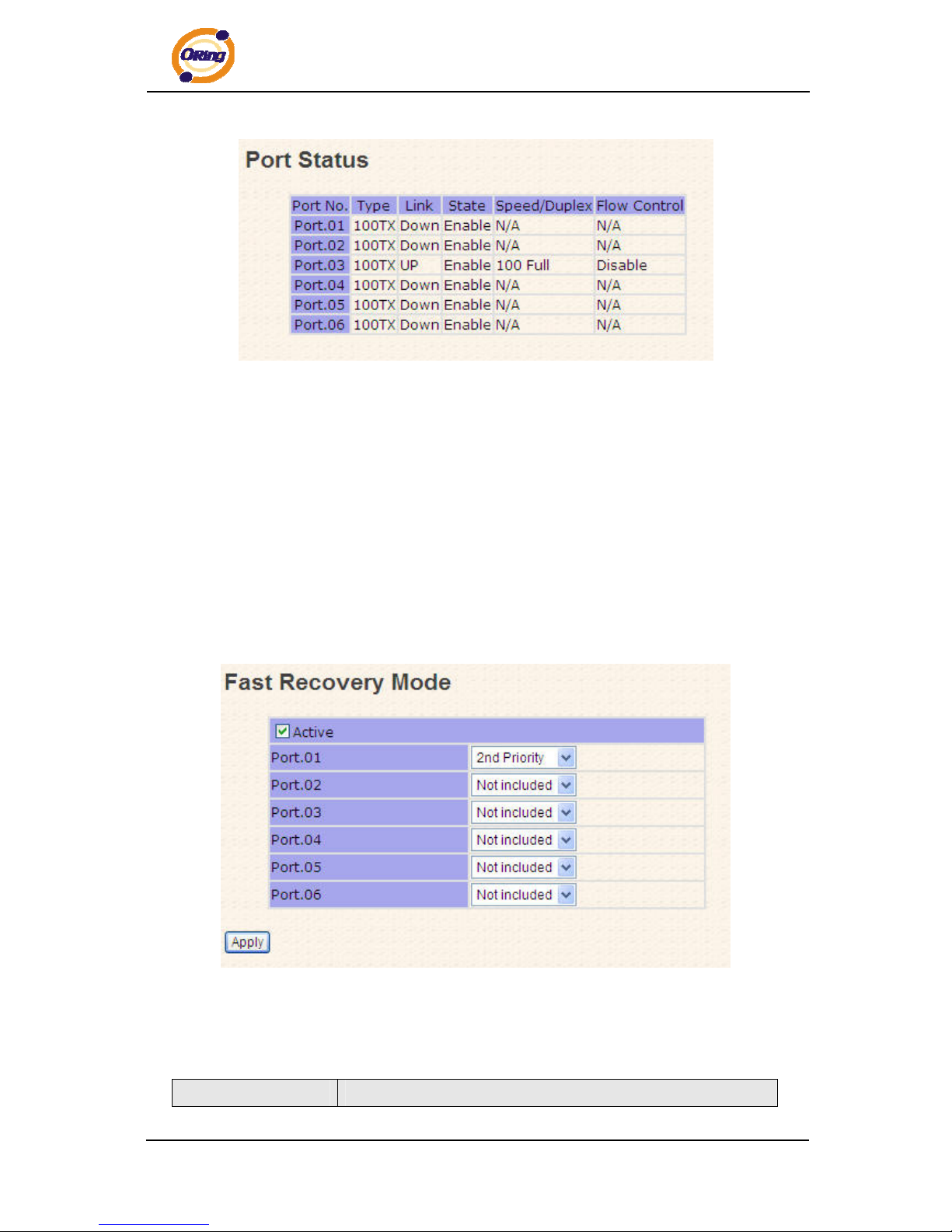
5.1.3.2 Port Status
The following information provides the current port status.
ORing Industrial Networking Corp.
23
Page 25
IPS-2042TX / 2042FX User’s Manual
Port Status interface
5.1.4 Redundancy
5.1.4.1 Fast Recovery Mode
The Fast Recovery Mode can be set to connect multiple ports to one or more switches.
The IPS-2042TX / 2042FX with its fast recovery mode will provide redundant links.
Fast Recovery mode supports 4 priorities, only the first priority will be the act port, the
other ports configured with other priority will be the backup ports.
Fast Recovery Mode interface
The following table describes the labels in this screen.
Label Description
ORing Industrial Networking Corp. 24
Page 26
IPS-2042TX / 2042FX User’s Manual
Active
Activate the fast recovery mode.
port
Port can be configured as 5 priorities. Only the port with highest
priority will be the active port. 1st Priority is the highest.
Apply
Click “Apply” to activate the configurations.
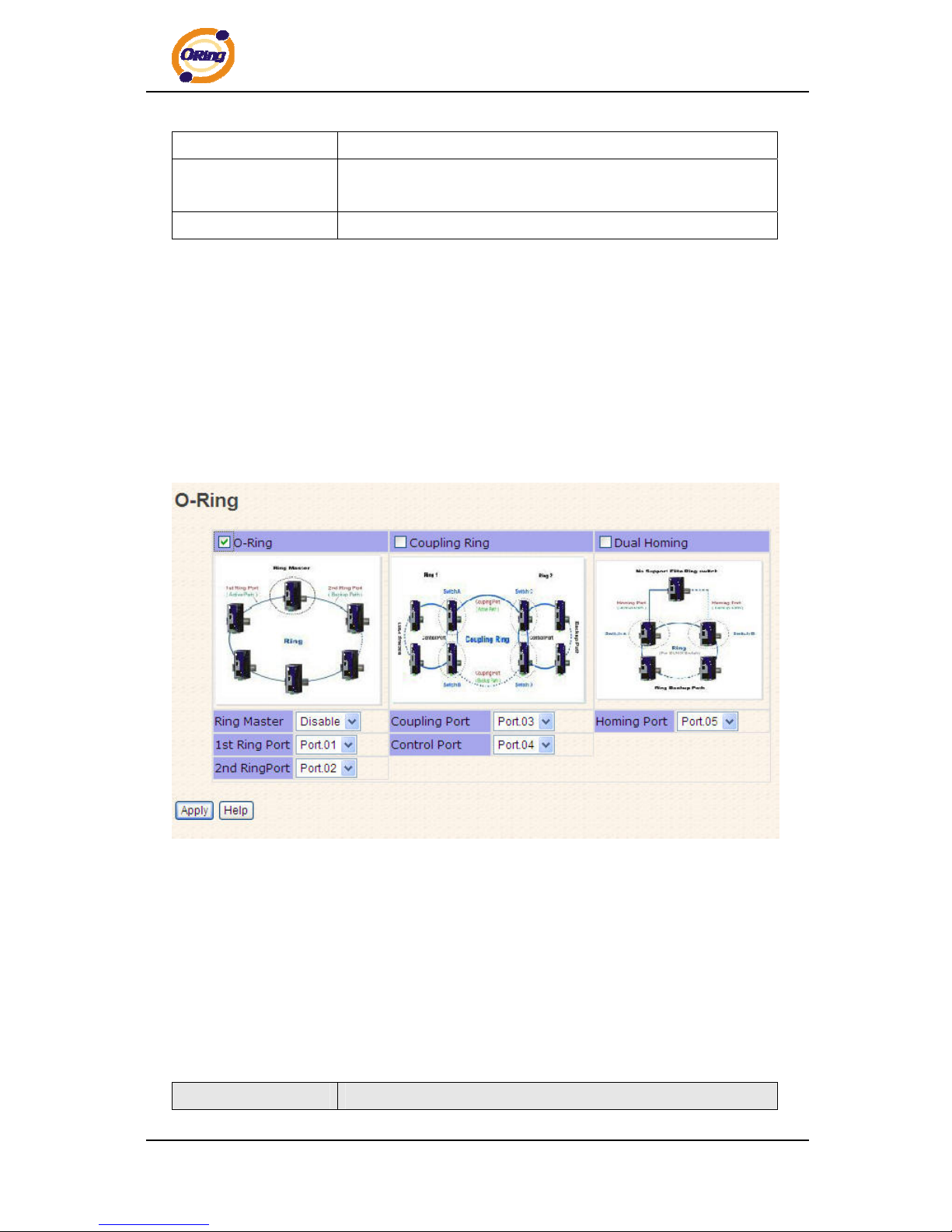
5.1.4.2 O-Ring
O-Ring is one of the most powerful Redundant Ring technology in the world. The
recovery time of O-Ring is less than 10 mS over 250 units of connections. It can
reduce unexpected malfunction caused by network topology change. O-Ring
technology supports three Ring topologies for network redundancy: O-Ring, Coupling
Ring and Dual Homing.
O-Ring interface
The following table describes the labels in this screen.
Label Description
ORing Industrial Networking Corp.
25
Page 27

IPS-2042TX / 2042FX User’s Manual
O-Ring
Mark to enable O-Ring.
Ring Master
There should be one and only one Ring Master in a ring.
However if there are two or more switches which set Ring Master
to enable, the switch with the lowest MAC address will be the
actual Ring Master and others will be Backup Masters.
1st Ring Port
The primary port, when this switch is Ring Master.
2nd Ring Port
The backup port, when this switch is Ring Master.
Coupling Ring
Mark to enable Coupling Ring. Coupling Ring can be used to
divide a big ring into two smaller rings to avoid effecting all
switches when network topology change. It is a good application
for connecting two O-Rings.
Coupling Port
Link to Coupling Port of the switch in another ring. Coupling
Ring need four switch to build an active and a backup link.
Set a port as coupling port. The coupled four ports of four
switches will be run at active/backup mode.
Control Port
Link to Control Port of the switch of the same ring. Control Port
used to transmit control signals.
Dual Homing
Mark to enable Dual Homing. By selecting Dual Homing mode,
O-Ring will be connected to normal switches through two RSTP
links (ex: backbone Switch). The two links work as
active/backup mode, and connect each O-Ring to the normal
switches in RSTP mode.
Apply
Click “Apply” to activate the configurations.
Note: We don’t suggest you to set one switch as a Ring Master and a Coupling Ring at the same time due to heavy
load.
5.1.4.3 RSTP
The Rapid Spanning Tree Protocol (RSTP) is an evolution of the Spanning Tree Protocol.
It provides faster spanning tree convergence after a topology change. The system also
supports STP and the system will auto detect the connected device that is running STP or
RSTP protocol.
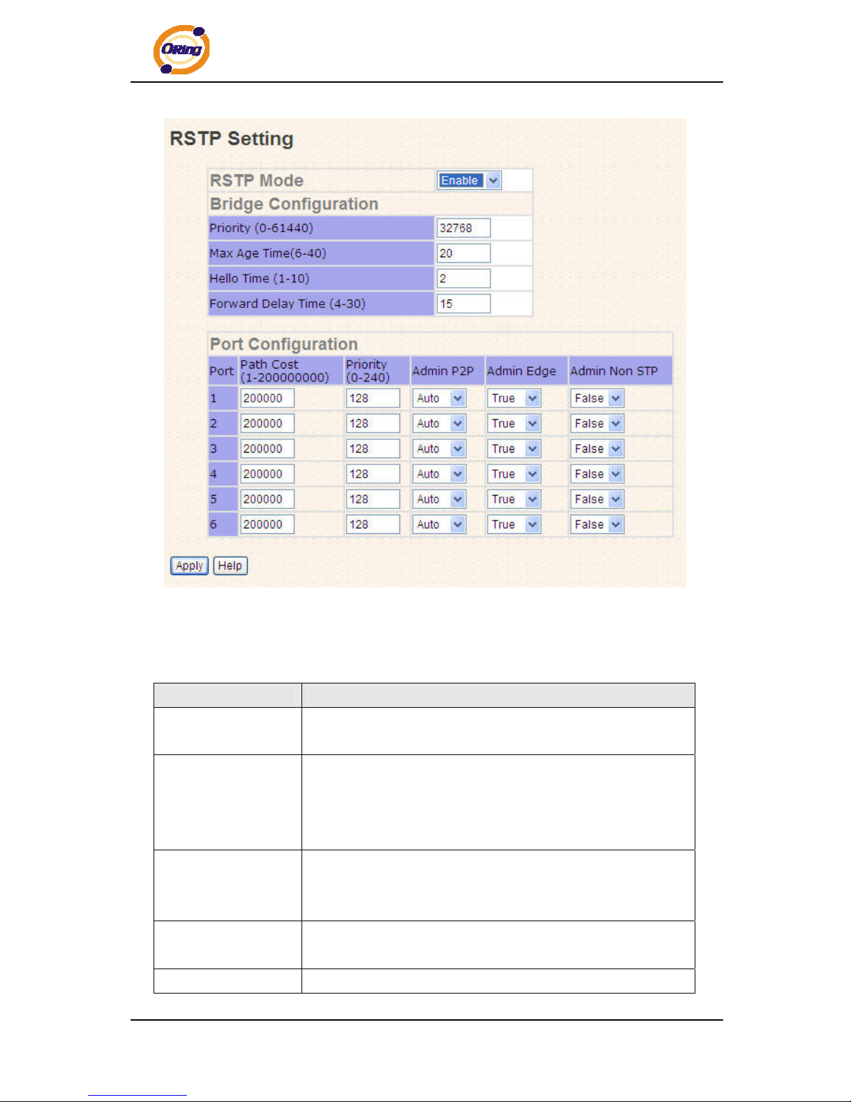
RSTP setting
You can enable/disable the RSTP function, and set the parameters for each port.
ORing Industrial Networking Corp. 26
Page 28
IPS-2042TX / 2042FX User’s Manual
RSTP Setting interface
The following table describes the labels in this screen.
Label Description
RSTP mode
You must enable or disable RSTP function before configuring the
related parameters.
Priority (0-61440)
A value used to identify the root bridge. The bridge with the
lowest value has the highest priority and is selected as the root.
If the value changes, you must reboot the switch. The value
must be multiple of 4096 according to the protocol standard rule.
Max Age (6-40)
The number of seconds a bridge waits without receiving
Spanning-tree Protocol configuration messages before attempting
a reconfiguration. Enter a value between 6 through 40.
Hello Time (1-10)
The time that controls switch sends out the BPDU packet to check
RSTP current status. Enter a value between 1 through 10.
Forwarding Delay
The number of seconds a port waits before changing from its
ORing Industrial Networking Corp.
27
Page 29

IPS-2042TX / 2042FX User’s Manual
Time (4-30)
Rapid Spanning-Tree Protocol learning and listening states to the
forwarding state. Enter a value between 4 through 30.
Path Cost
(1-200000000)
The cost of the path to the other bridge from this transmitting
bridge at the specified port. Enter a number 1 through
200000000.
Priority (0-240)
Decide which port should be blocked by priority in LAN. Enter a
number 0 through 240. The value of priority must be the multiple
of 16
Admin P2P
Some of the rapid state transactions that are possible within
RSTP are dependent upon whether the port concerned can only
be connected to exactly one other bridge (i.e. It is served by a
point-to-point LAN segment), or it can be connected to two or
more bridges (i.e. It is served by a shared medium LAN segment).
This function allows the P2P status of the link to be manipulated
administratively. True means P2P enabling. False means P2P
disabling.
Admin Edge
The port is directly connected to end stations, and it cannot create
bridging loop in the network. To configure the port as an edge
port, set the port to “True”.
Admin Non STP
The port includes the STP mathematic calculation. True is not
including STP mathematic calculation. False is including the
STP mathematic calculation.
Apply
Click “Apply” to activate the configurations.
NOTE: Follow the rule to configure the MAX Age, Hello Time, and Forward Delay Time:
2 x (Forward Delay Time value –1) ≥ Max Age value ≥ 2 x (Hello Time value +1)
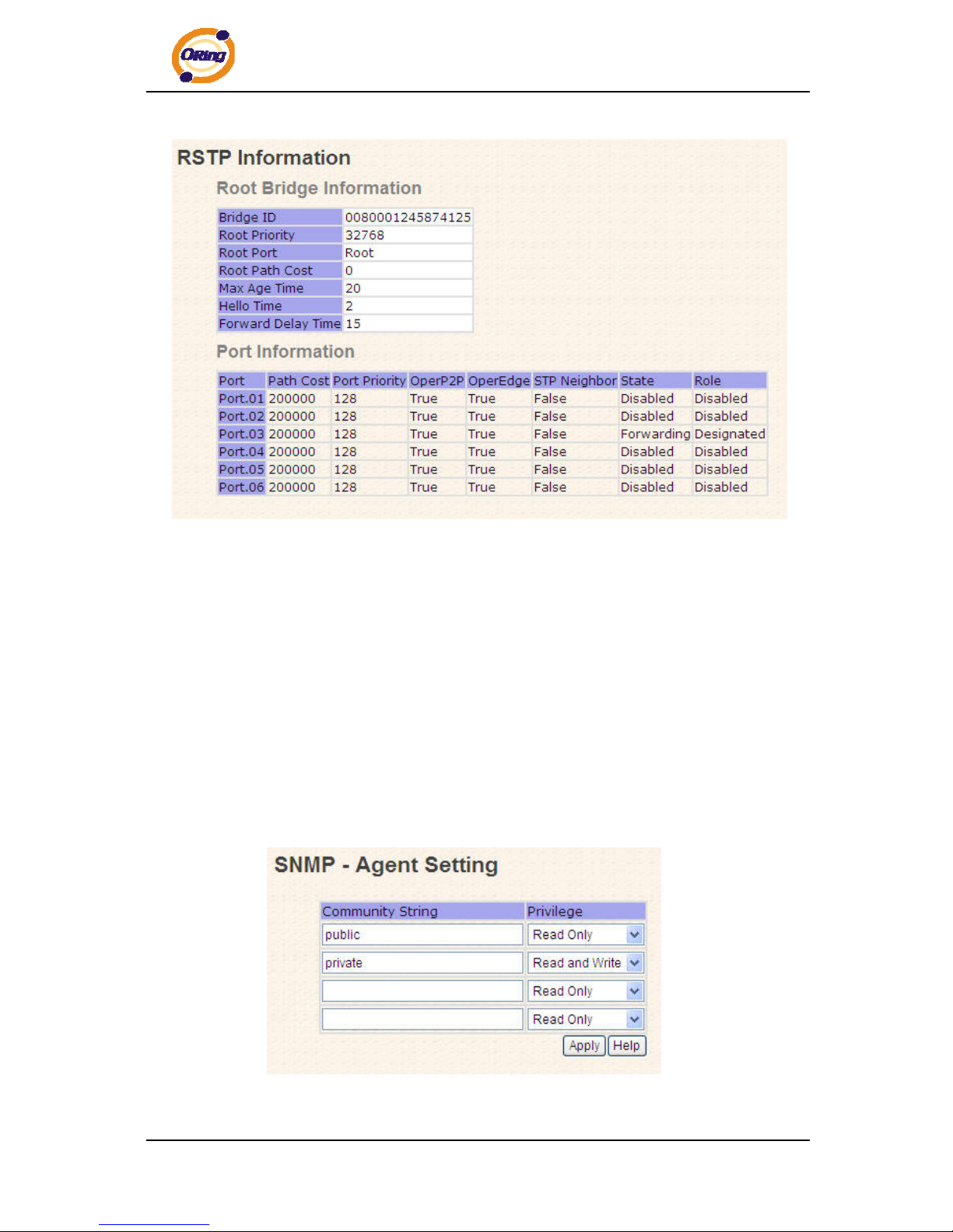
RSTP Information
Show RSTP algorithm result at this table.
ORing Industrial Networking Corp. 28
Page 30
IPS-2042TX / 2042FX User’s Manual
RSTP Information interface
5.1.5 SNMP Configuration
Simple Network Management Protocol (SNMP) is the protocol developed to manage
nodes (servers, workstations, routers, switches and hubs etc.) on an IP network. SNMP
enables network administrators to manage network performance, find and solve network
problems, and plan for network growth. Network management systems learn of problems
by receiving traps or change notices from network devices implementing SNMP.
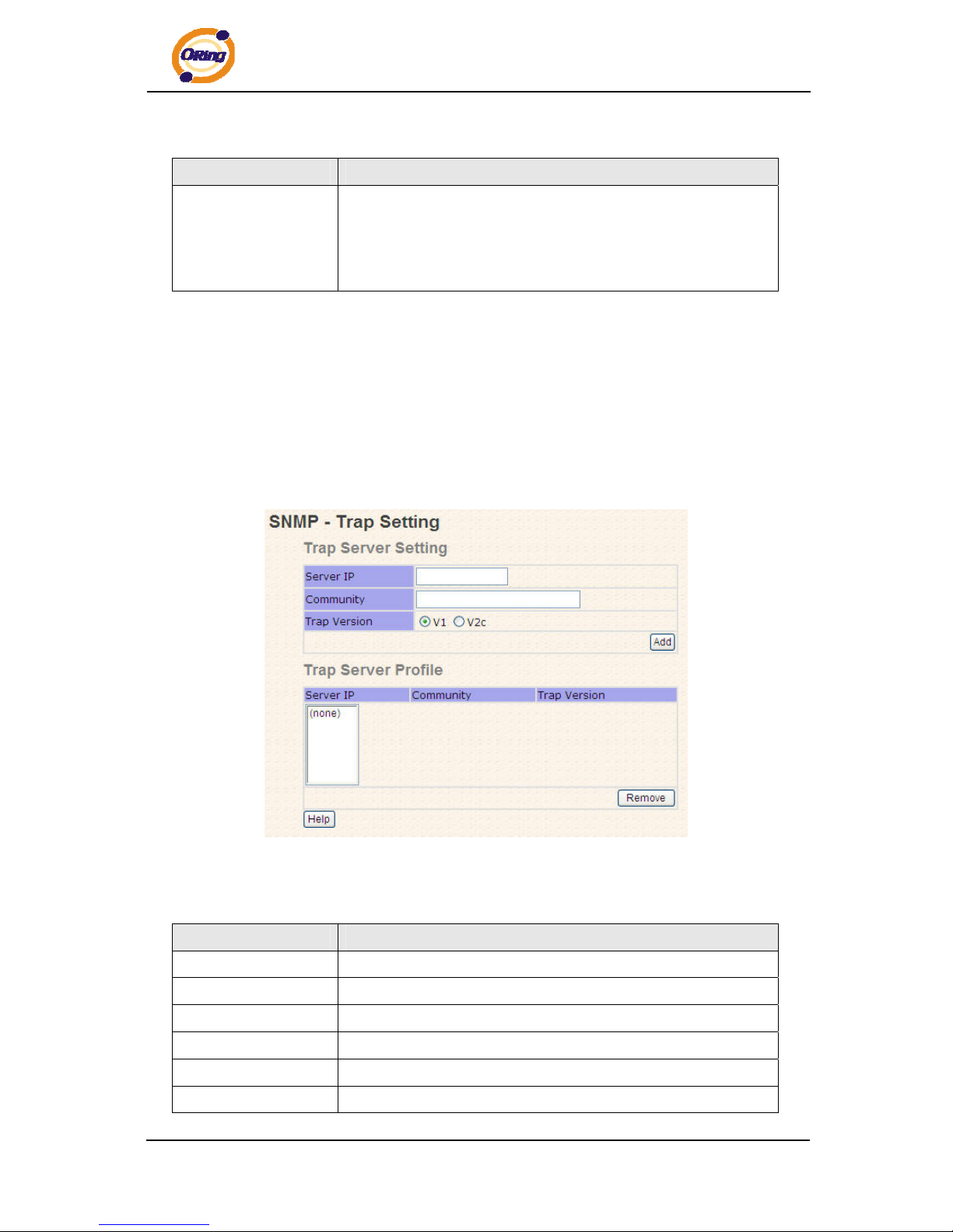
5.1.5.1 SNMP – Agent Setting
You can set SNMP agent related information by Agent Setting Function.
SNMP – Agent Setting interface
ORing Industrial Networking Corp.
29
Page 31
IPS-2042TX / 2042FX User’s Manual
The following table describes the labels in this screen.
Label Description
SNMP – Agent
Setting
SNMP Community should be set for SNMP. Four sets of
"Community String/Privilege" are supported. Each Community
String is maximum 32 characters. Keep empty to remove this
Community string.
5.1.5.2 SNMP –Trap Setting
A trap manager is a management station that receives traps, the system alerts
generated by the switch. If no trap manager is defined, no traps will issue. Create a
trap manager by entering the IP address of the station and a community string. To
define management stations as trap manager and enter SNMP community strings and
selects the SNMP version.
SNMP –Trap Setting interface
The following table describes the labels in this screen.
Label Description
Server IP
The server IP address to receive Trap
Community
Community for authentication
Trap Version
Trap Version supports V1 and V2c.
Add
Add trap server profile.
Remove
Remove trap server profile.
Help
Show help file.
ORing Industrial Networking Corp. 30
Page 32
IPS-2042TX / 2042FX User’s Manual
ORing Industrial Networking Corp.
31
5.1.6 VLAN
A Virtual LAN (VLAN) is a logical network grouping that limits the broadcast domain, which
allows you to isolate network traffic. Only the members of the VLAN will receive traffic
from the same members of VLAN. Basically, creating a VLAN from a switch is logically
equivalent of reconnecting a group of network devices to another Layer 2 switch.
However, all the network devices are still plugged into the same switch physically.
The switch supports port-based VLAN only.
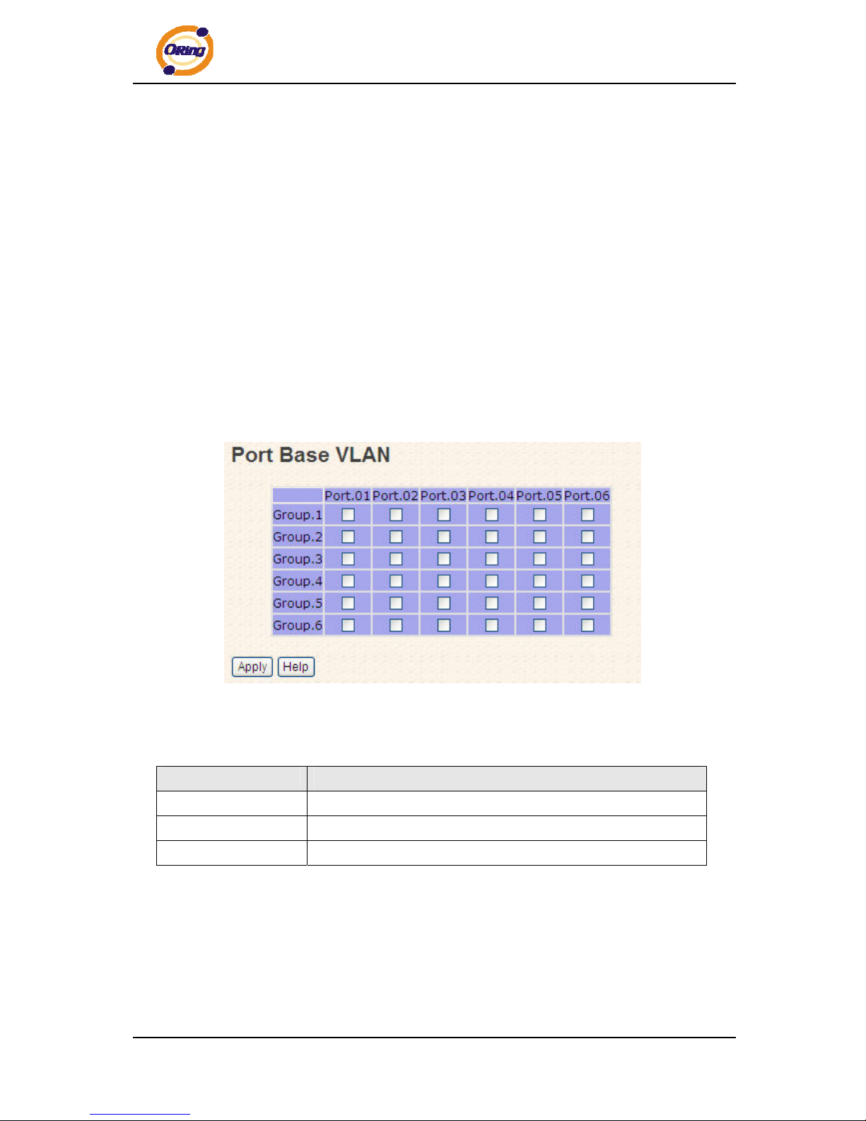
5.1.6.1 VLAN Configuration – Port Based
Packets can go among only members of the same VLAN group. Note all unselected
ports are treated as belonging to another single VLAN. If the port-based VLAN enabled,
the VLAN-tagging is ignored.
VLAN Configuration – P
e following table d labels in this screen.
ort Based VLAN interface
Th escribes the
Label Description
Group
Mark the blank to assign the port into VLAN group.
Apply
activate the configurations. Click “Apply” to
Help
Show help file.
5
ing message will send to your appointed server,
.1.7 Warning
Warning function is very important for managing switch. You can manage switch by
SYSLOG, E-MAIL, and Fault Relay. It helps you to monitor the switch status on remote
site. When events occurred, the warn
Page 33
IPS-2042TX / 2042FX User’s Manual
ORing Industrial Networking Corp. 32
E-MAIL, or relay fault to switch panel.
5.1.
ult ED in switch panel will light up
nd the electric relay will signal at the same time.
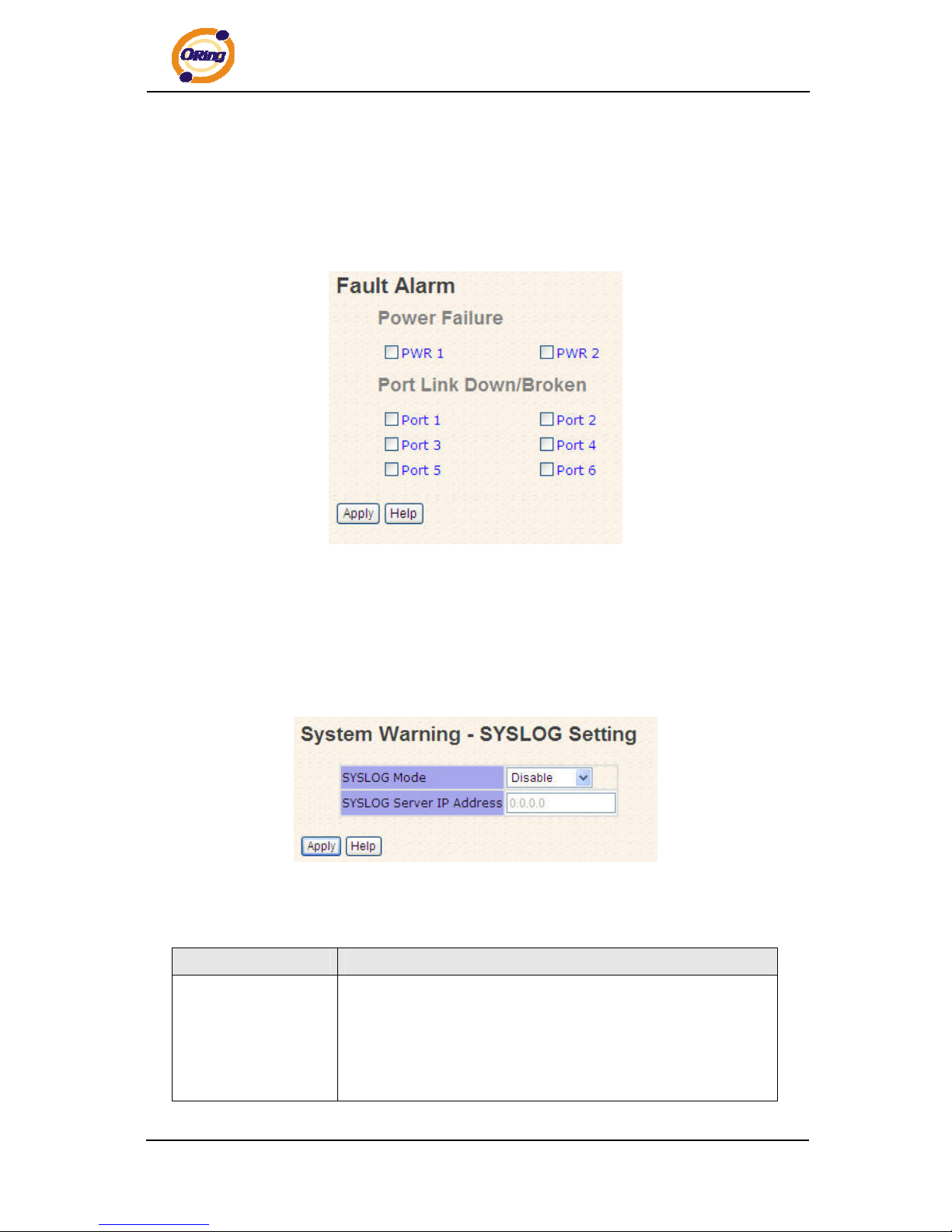
7.1 Fault Alarm
When any selected fault event is happened, the Fa L
a
Fault alarm interface
essages across networks.
Please refer to RFC 3164 - The BSD SYSLOG Protocol
System Warning – SYSLOG Setting
The SYSLOG is a protocol to transmit event notification m
System Warning – SYSLOG Setting interface
e following table d labels in this screen.
Th escribes the
Label Description
SYSLOG Mode
Both: log to both of local and remote server.
Disable: disable SYSLOG.
Client Only: log to local system.
Server Only: log to a remote SYSLOG server.
Page 34
IPS-2042TX / 2042FX User’s Manual
ORing Industrial Networking Corp.
33
SYSLOG Server IP
The remote SYSLOG Server IP address.
Address
Apply
activate the configurations. Click “Apply” to
Help
Show help file.
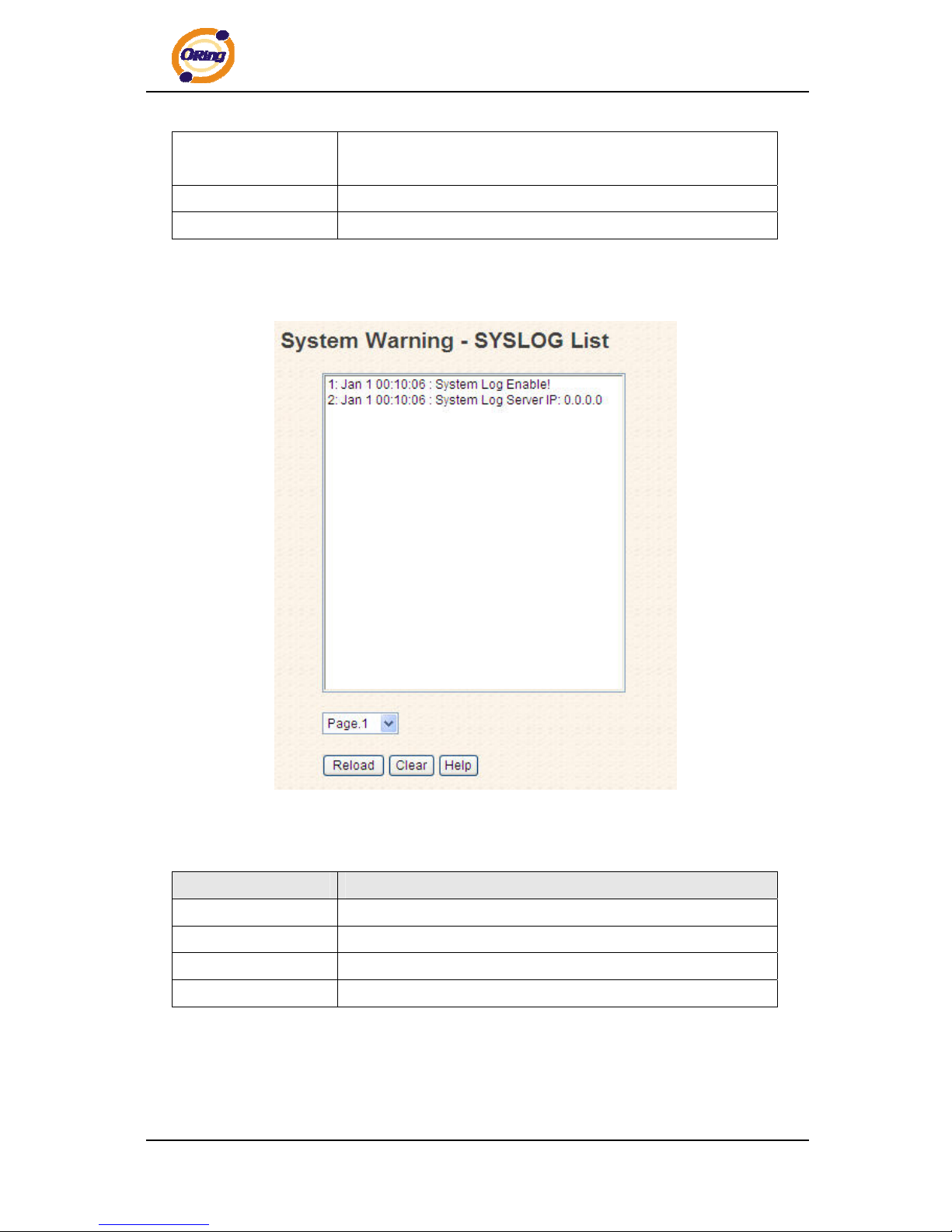
System Event LOG
If system log client is enabled, the system event logs will show in this table.
System event log interface
e following table d labels in this screen.
Th escribes the
Label Description
Page
Select LOG page.
Reload
ewest event logs and refresh this page. To get the n
Clear
Clear log.
Help
Show help file.
on across the Internet. Please refer to RFC 821 - Simple Mail Transfer
System Warning – SMTP Setting
The SMTP is Short for Simple Mail Transfer Protocol. It is a protocol for e-mail
transmissi
Page 35
IPS-2042TX / 2042FX User’s Manual
ORing Industrial Networking Corp. 34
Protocol.
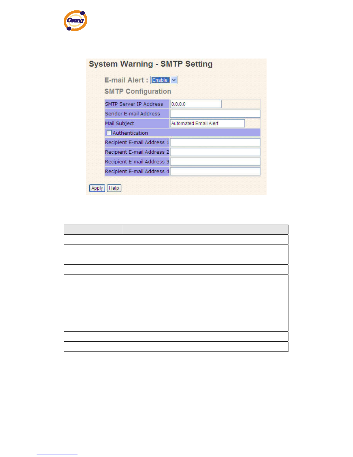
System Warning – SMTP Setting interface
e following table d labels in this screen. Th escribes the
Label Description
E-mail Alarm
Enable/Disable transmission system warning events by e-mail.
Sender E-mail
The SMTP server IP address
Address
Mail Subject
The Subject of the mail
Authentication
Confirm Password: re-enter password.
Username: the authentication username.
Password: the authentication password.
Recipient E-mail
cipient's E-mail address. It supports up to 6 recipients per
Address
The re
mail.
Apply
activate the configurations. Click “Apply” to
Help
Show help file.
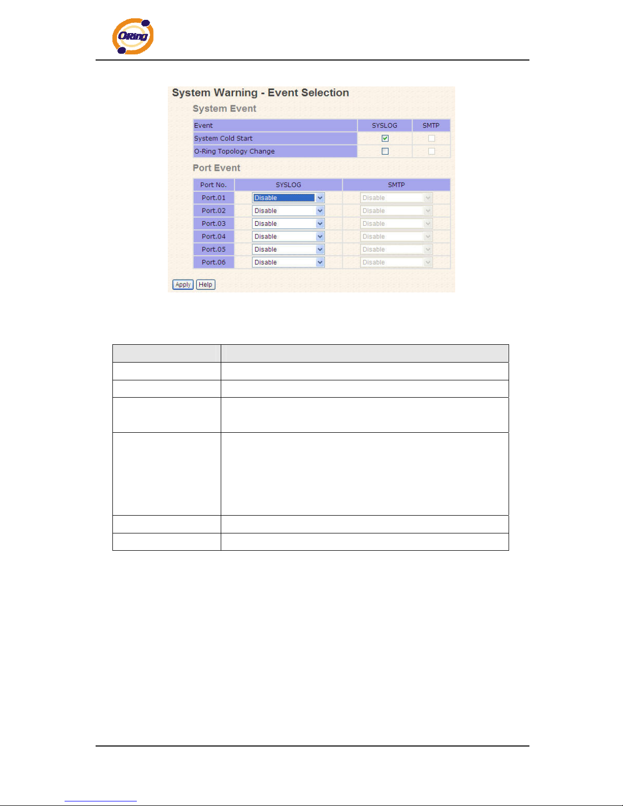
System Warning – Event Selection
SYSLOG and SMTP are the two warning methods that supported by the system.
Check the corresponding box to enable system event warning method you wish to
choose. Please note that the checkbox can not be checked when SYSLOG or SMTP is
disabled.
Page 36
IPS-2042TX / 2042FX User’s Manual
System Warning – Event Selection interface
The following table describes the labels in this screen.
Label Description
System Event
System Cold Start
Alert when system restart
O-Ring T opology
Change
Alert when O-Ring topology change
Port Event Disable
Link Up
Link Down
Link Up & Link Down
Apply
Click “Apply” to activate the configurations.
Help
Show help file.
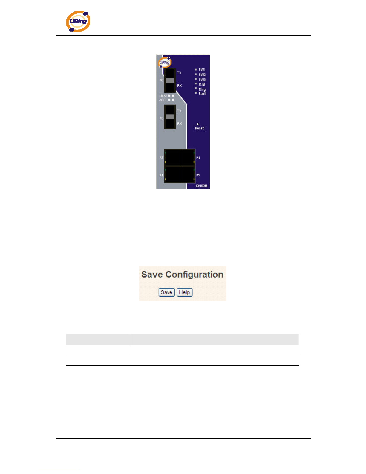
5.1.8 Front Panel
Show IPS-2042TX / 2042FX panel. Click “Close” to close panel on web.
ORing Industrial Networking Corp.
35
Page 37
IPS-2042TX / 2042FX User’s Manual
Front panel interface
5.1.9 Save Configuration
If any configuration changed, “Save Configuration” should be clicked to save current
configuration data into the permanent flash memory. Otherwise, the current configuration
will be lost when power off or system reset.
System Configuration interface
The following table describes the labels in this screen.
Label Description
Save
Save all configurations.
Help
Show help file.
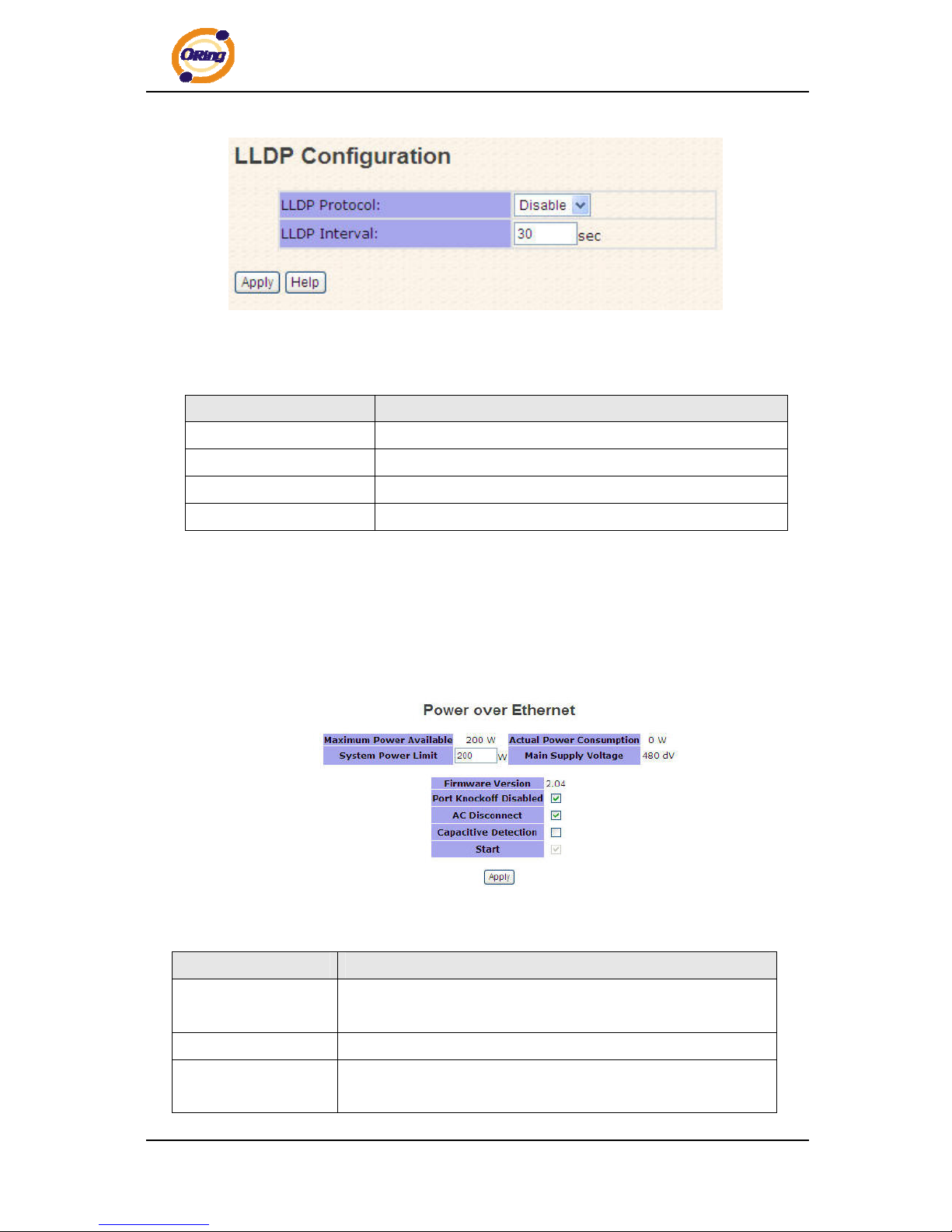
5.1.10 LLDP
LLDP (Link Layer Discovery Protocol) function allows the switch to advertise its
information to other nodes on the network and store the information it discovers.
ORing Industrial Networking Corp. 36
Page 38
IPS-2042TX / 2042FX User’s Manual
LLDP interface
The following table describes the labels in this screen.
Label Description
LLDP Protocol
“Enable” or “Disable” LLDP function.
LLDP Interval
The interval of resend LLDP (by default at 30 seconds)
Apply
Click “Apply” to activate the configurations.
Help
Show help file.
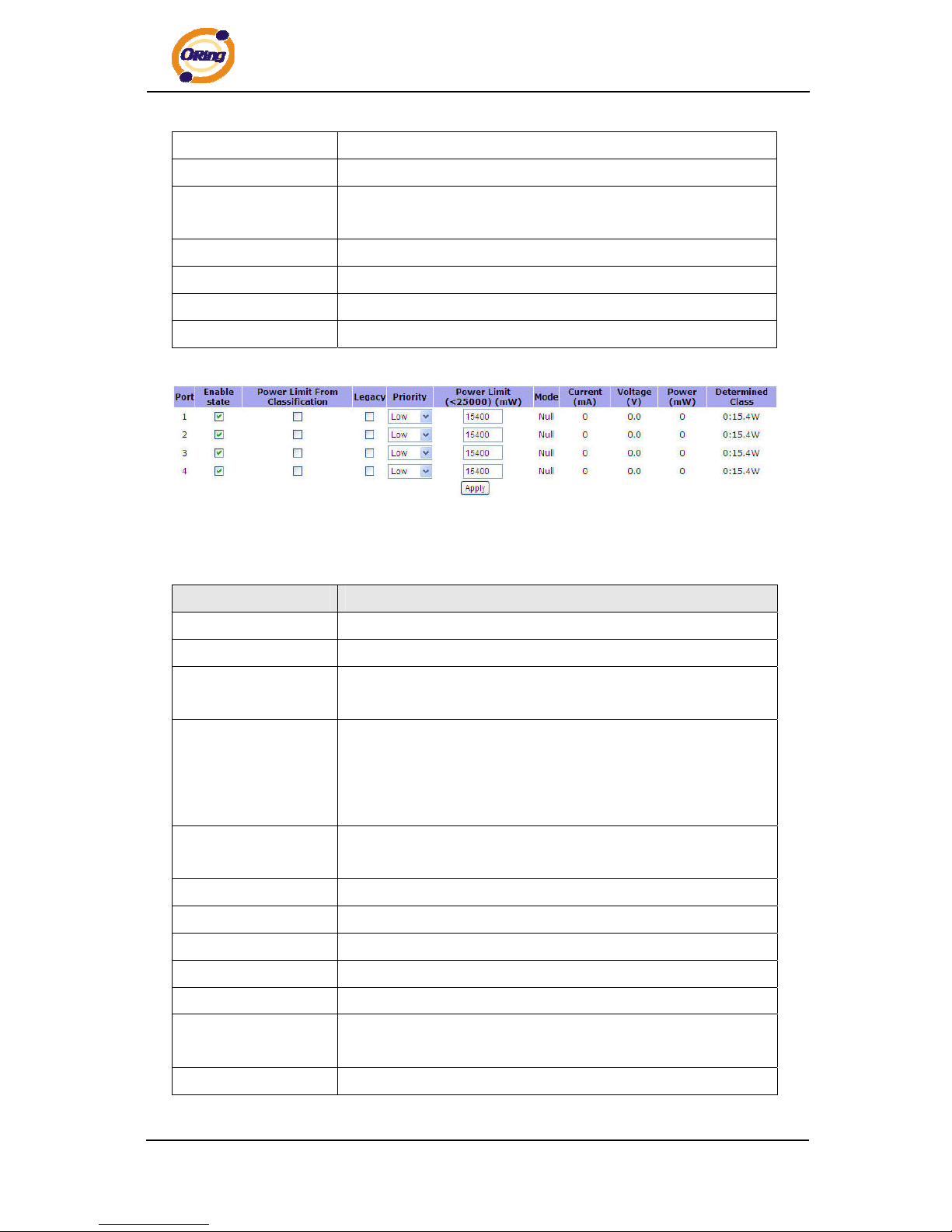
5.1.11 Power over Ethernet (P.O.E.)
The following interface is the PoE setting interface. There are 4 ports (port 1 to port 4) act
as PSE (Power Supply Equipment) ports.
The following table describes the labels in this screen.
Label Description
Maximum Power
Available
Display the maximum power available.
System Power Limit
Set the system power limit.
Actual Power
Consumption
Display the actual power consumption.
ORing Industrial Networking Corp.
37
Page 39
IPS-2042TX / 2042FX User’s Manual
Main Supply Voltage
Display the main supply voltage.
Firmware Version
Display the firmware version.
Pork Knockoff
Disabled
Mark the blank to enable “Pork Knock off Disabled” function.
AC Disconnect
Mark the blank to enable “AC Disconnect” function.
Capacitive Detection
Mark the blank to enable “Capacitive Detection” function
Start
Mark the blank to enable “P.O.E .” function.
Apply
Click “Apply” to set the configurations.
P.S.E. port control setting interface
The following table describes the labels in this screen.
Label Description
Port
Port number.
Enable state
Mark the blank to enable P.O.E. function for specific ports
Power Limit From
Classification
Set the “Power Limit From Classification” function for each
P.O.E. ports
Legacy
The legacy detection is to identify the PD devices that did not
follow the IEEE 802.3af standard their unique electrical signatures
in order for the PoE switch can provide the power to those PD
devices
Priority
Set port priority for the P.O.E. power management. 1 = C (critical),
2 = H (High), 3 = L (Low)
Power Limit
Set the power limit value. The maximum value must less 15400
Mode
Display the PD current operation mode status
Current(mA)
Display current value
Voltage(V)
Display voltage value
Power(mW)
Display watt value
Determined Class
Display power class. When the Bypass classification enable, the
class value will not show in here
Apply
Click “Apply” to set the configurations.
ORing Industrial Networking Corp. 38
Page 40

IPS-2042TX / 2042FX User’s Manual
Technical Specifications
Technology
Ethernet Standards IEEE802.3 10BASE-T
IEEE802.3u 100BASE-TX
IEEE802.3x Flow Control and Back pressure
IEEE802.3af Power over Ethernet specification
IEEE802.1D Spanning tree protocol
IEEE802.1w Rapid Spanning tree protocol
IEEE802.1AB LLDP
MAC addresses 1024
Flow Control IEEE 802.3x Flow Control and Back-pressure
VLAN Port based
Processing Store-and-Forward
Firmware upgrade TFTP
Ring redundancy
RSTP
O-Ring
Couple Ring
Dual Homing
Fast recovery
Interface
RJ45 Ports 10/100Base-T(X), Auto MDI/MDI-X (4x P.O.E. PSE)
Fiber Ports 100 Base-FX(SC Connector)
Multi-Mode:
0 to 2 km, 1310 nm (50/125 µm to 62.5/125 µm)
Single-Mode:
0 to 30 km, 1310 nm (9/125 µm)
LED Indicators Per Unit : Power x 3(Green)
RJ45 Ports:
Per Port : Link/Activity(Green/Blinking Green), Full
duplex(Amber)
P.O.E. LED: P.O.E. power supplied(Green)
Fiber Ports:
Per Port : Activity(Green), Link (Amber)
Power Requirements
Power Input Voltage PWR1/2: +48V DC in 7 pin Terminal block
ORing Industrial Networking Corp.
39
Page 41

IPS-2042TX / 2042FX User’s Manual
PWR3: +48VDC in Power Jack
Reverse Polarity Protection Present
Power Consumption 7 Watts (Power supplied for PD not included)
Environmental
Wide Operating Temperature -40 to 70
o
C
Storage Temperature -40 to 85oC
Operating Humidity 5% to 95%, non-condensing
Mechanical
Dimensions(W x D x H) 52 mm(W)x 106 mm( D )x 144 mm(H)
Casing IP-30 protection
Regulatory Approvals
Regulatory Approvals FCC Part 15, CISPER (EN55022) class A
EMS EN61000-4-2 (ESD), EN61000-4-3 (RS), EN61000-4-4
(EFT), EN61000-4-5 (Surge), EN61000-4-6 (CS)
Shock IEC 60068-2-27
Free Fall IEC 60068-2-32
Vibration IEC 60068-2-6
Warranty
5 years
ORing Industrial Networking Corp. 40
 Loading...