

Page 1
LNK
ETH 100M
1
2
IMC-B111ETB-RJ45
P1 P2
Auto
Master
Manual
Slave
Ext.
ACT
Ext.Mode
LNK
ETH 100M
1
2
IMC-B111ET-TB
P1 P2
Ext.
ACT
Auto
Master
Manual
Slave
Ext.Mode
Quick InstallationGuide
Version 1.0
Quick Installation Guide
Introduction
PRINTED ON RECYCLED PAPER
QIG
IMC-B111ETB Series
1907-2-29-IMCB111ETB-1.0
The is acost-effective solution forextending an
Ethernet connectionbeyond its inherentdistance limitation. Theseries
includes modelsusing -RJ45 orterminal block interfaces.The -RJ45 model
extends thedistance to 300meters using aUTP cable or200meters using a
24AWG cable,and the terminalblock model extendsthe distance to
200meters usinga 24AWG cable.The -RJ45 model supports2/4/8-wired
auto detecting transmission, and the TB model supports 2-wired
transmission. The series providesa wide operating temperature range
from -40~75 C,making it suitable for harsh operating environments.
IMC-B111ETBseries
o
Package Contents
Installation
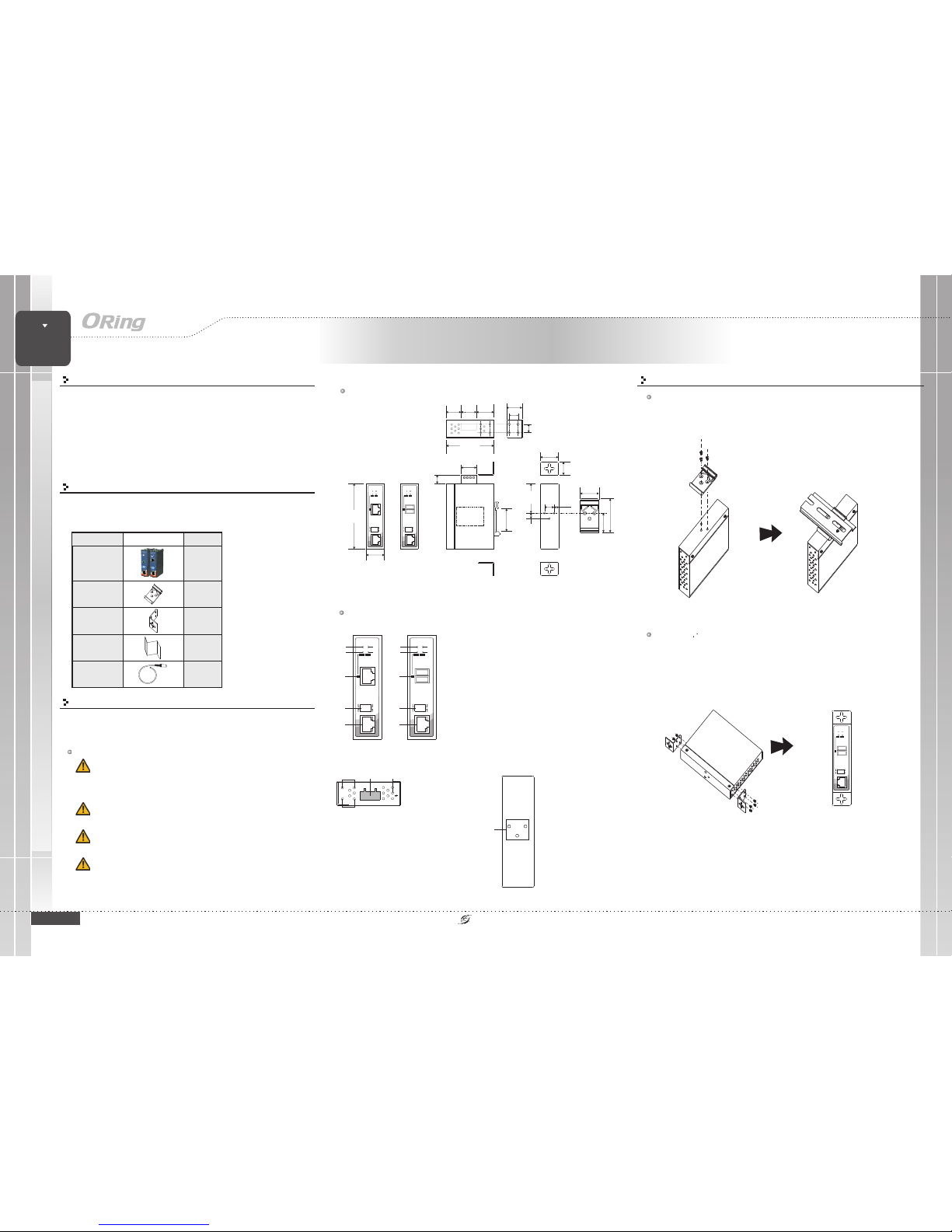
The series isshipped with thefollowing items. Ifany of theseitems is missing
or damaged,please contact yourcustomer service representativefor
assistance.
Preparation
Before installation, makesure you have all of the package contents
available and a PC with MicrosoftInternet Explorer 6.0 or later, forusing
web-based system management tools.
Elevated OperatingAmbient:
ReducedAir Flow:
Mechanical Loading:
Circuit Overloading:
If installed in a closed cabinet, the operating
ambient temperatureof the rackenvironment may begreater than roomambient.
Therefore, considerationshould be givento installing theequipment in an
environment compatiblewith the maximumambient temperature (Tma)specified
by themanufacturer.
Installation of the equipment should be such that the
amount of air flow required for safe operation of the equipment is not
compromised.
Mounting of the equipment in the d should be
such that a hazardous condition is not achieved due to uneven mechanical
loading.
Consideration shouldbe given tothe connection ofthe
equipment tothe supply circuitand the effectthat overloading ofthe circuits
might haveon overcurrent protectionand supply wiring.Appropriate
consideration ofequipment nameplate ratingsshould be used when addressing
this concern.
in-rail
Safety & Warnings
Contents
Wall-mountKit
DIN-rail Kit
IMC-B111ETB-TBor
IMC-B111ETB-RJ45
Pictures Number
X2
X1
QIG
X1
Dimension (Unit: mm)
Panel Layouts
Front Panel
1. PWR1LED
2. PWR2LED
3. Indicatorfor extension portaction
4. Indicatorfor extension portconnection status
5. Extensionport (terminal blockfor -TB
modelandRJ45portfor-RJ45model)
6. DIPswitch for modeselection of extensionport
7. LANPort
2
IMC-B111ETB Series
X1
70.0
20.0
43.5
8.0
14.0
6.05
23.0
50.0
25.3
33.6
12.5
12.3
13.1
22.6
26.1
19.0
26.1
95.0
28.0
20.0
22.0
1
6
7
5
TopPanel
G
112 3
1. Wall-mountscrew
holes
2. Terminalblock
3. Frameground
Real Panel
1
1. Din-railscrew holes
Step 1:
Step 2:
Slant the switch and screw the Din-railkit onto theback of theswitch, right in the
middle of the back panel.
Slide theswitch onto a DIN-railfrom the Din-railkit and makesure the switchclicks into
the railfirmly.
DIN-rail Installation
Step 1:
Step 2:
Step 3:
Screw the twopieces of wall-mount kits onto bothsides of the switch. A
total of eightscrews are required, as shown below.
Use the switch,with wall mount plates attached, as a guide to mark the correct
locations of the four screws.
Insert four screwheads through the large parts ofthe keyhole-shaped apertures, and
then slide theswitch downwards. Tighten the fourscrews for added stability.
Wall-mounting
Industrial Extended Media Converter
Media
Converter
Media
Converter
INDUSTRIAL
43
2
1
6
7
5
4
3
LNK
ETH 10/100M
1
2
IMC-B111ET-TB
P1 P2
Ext.
ACT
Auto
Master
Manual
Slave
Ext.Mode
DC plug
X1
1
8
.
.
.
.
.
.
1
2
LNK
ETH 100M
1
2
IMC-B111ETB-RJ45
P1 P2
Auto
Master
Manual
Slave
Ext.
ACT
Ext.Mode
LNK
ETH 100M
1
2
IMC-B111ET-TB
P1 P2
Ext.
ACT
Auto
Master
Manual
Slave
Ext.Mode
1
8
.
.
.
.
.
.
1
2
Page 2
QIG
Quick InstallationGuide
PRINTED ON RECYCLED PAPER
Quick Installation Guide
ORing IndustrialNetworking Corp.
Copyright© 2014 ORing
All rightsreserved.
TEL: +886-2-2218-1066
FAX:+886-2-2218-1014
Website: www.oring-networking.com
E-mail: [email protected]
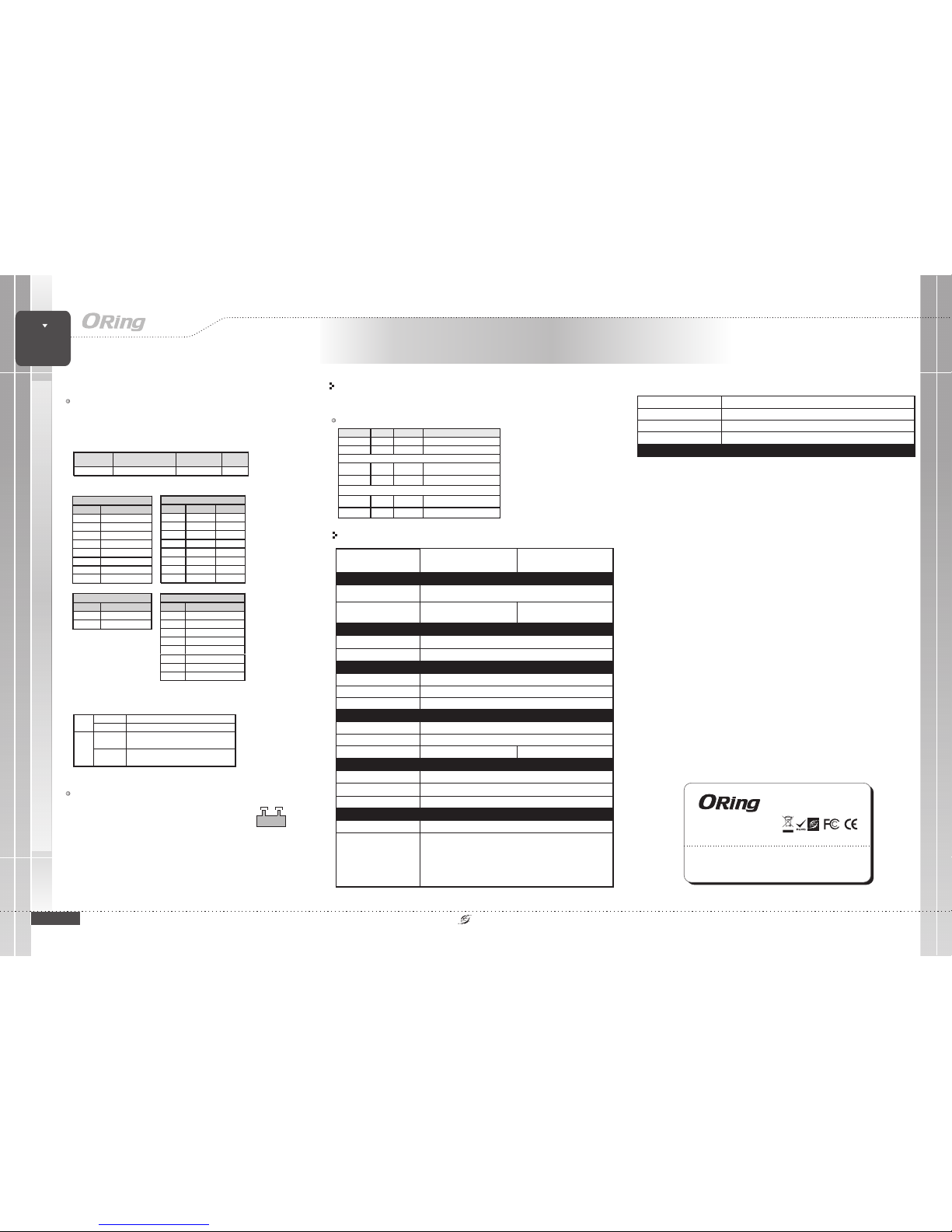
The switch supports dual redundant power supplies which are
located on the 4-pin terminal block.
Insert the negative/positive wires into the V-/V+
terminals, respectively.
To keep the DC wires from pulling loose, use a small
flat-blade screwdriver to tighten the wire-clamp screws on the
front of the terminalblock connector.
STEP 1:
STEP 2:
Version 1.0
QIG
Configurations
After installingthe device and connecting cables, the greenpower LED shouldturn on.
Please referto the followingtablet for LEDindication.
LED indication table
Specifications
Wiring
PWR2
V2+ V2-
PWR1
V1+ V1-
ORing Extended
Converter Model
IMC-B111ETB-TB
100Base-TXPorts in RJ45
Auto MDI/MDIX
1
Physical Ports
Technology
Ethernet Standards
IEEE 802.3ufor 100Base-TX
Power
Input power
Power consumption(Typ.)
Dual 12~48VDC power inputsat 4-pin terminalblock
2Watts
Overload currentprotection
Present
Physical Characteristic
Enclosure
IP-30
Dimension(WxDxH)
26.1(W) x70(D) x 95(H)mm(1.03x 2.76 x3.74inch.)
Weight (g )
Environmental
-40to85C(-40to185F)
oo
Storage Temperature
Operating Temperature
5% to95% Non-condensingOperating Humidity
Regulatory Approvals
FCC Part15, CISPR (EN55022)class AEMI
EN61000-4-2 (ESD),
EN61000-4-3 (RS),
EN61000-4-4 (EFT),
EN61000-4-5 (Surge),
EN61000-4-6 (CS),
EN61000-4-8,
EN61000-4-11
EMS
IEC60068-2-27Shock
IEC60068-2-32
IEC60068-2-6Vibration
EN60950-1
Safety
Free Fall
Warranty
5years
Processing
Store-and-Forward
240 g
-40to75C(-40to167F)
oo
Network Connection
The has astandard Ethernet port.According tothe link type,the
device uses CAT 3,4,5,5e UTP cables to connect to any other network devices
(PCs, servers, switches, routers,or hubs). Pleaserefer to thefollowing table forcable
specifications.
IMC-B111ETB-RJ45
Cable Typesand Specifications:
Cable Type Max. Length Connector
100BASE-TX Cat.5 100-ohmUTP UTP100 m(328 ft) RJ-45
For pinassignments for differenttypes of cables,please refer tothe following tables.
100Base-TX R J-45
PinNumber Assignment
1TD+
2TD-
3RD+
4Notused
5Notused
6RD-
7Notused
8Notused
100Base-TX MDI/MDI-X
Pin Number MDIport MDI-Xport
1 TD+(transmit) RD+(recei ve)
2 TD-(tran smit) RD-(recei ve)
3 RD+(receive) TD+(transmit)
4NotusedNotused
5NotusedNotused
6 RD-(receive) TD-(transm it)
7NotusedNotused
8NotusedNotused
DIP SwitchFunction
ON Maste r Mode: Devicesoperatesinmastermode1
OFF SlaveMode: Devices o perates in slave m ode
ON ManualMode:Configuresthemastermodeorslave
modemanuallybasedonDIP-switch1settings
2*
OFF AutoMode: Conducts auto negotiatio n and
configuration for the master or slave mode
LED Color Status Description
PW1 Green On DC power mod ule 1 activated
PW2
Green On DC power mod ule 2 activated
10/100Base-TX R J45 Port
LNK Green On Port is linked
ACT Amber On
Transm itt ing da ta
Ethernet Extender Port
LNK Green On Port is linked
ACT Amber On
Transm itt ing da ta
IMC-B111ETB-RJ45
100Mbps EthernetExtender
Ports
1 (support2-wired on
terminal block)
1 (support2/4/8-wired auto
detecting onRJ45 connector)
242 g
IMC-B111ETB Series
Industrial Extended Media Converter
Media
Converter
Media
Converter
INDUSTRIAL
IMC-B111ETB Series
100MbpsExtension port TerminalBlock
PinNumber Assignment*
1D1+
2D1-
100MbpsExtension port Terminal Block
Pin Number Ass ignment*
1D1+
2D1-
3D2+
4D3+
5D3-
6D2-
7D4+
8D4-
* Pleasenotice Manual modecan’t connect toAuto mode.
Note: “+”and “-” signsrepresent the polarityof the wiresthat
make upeach wire pair.
 Loading...