

Page 1
IGS-9080
PWR
PWR1
PWR2
R.M
Ring
Fault
10/100/
1000T
G3
G4
G1
G2
G7
G8
G5
G6
Reset
Quick InstallationGuide
Version 1.0
Quick Installation Guide
Introduction
PRINTED ON RECYCLED PAPER
The is a managed industrial Ethernet switch with eight
10/100/1000Base-T(X) ports. The seriesconsists of the and
models to meet different application needs. The former
supports IEEE 1588v2 clock synchronization while thelatter does not.
The switchsupports Ethernet Redundancyprotocol, O-Ring (recoverytime
< 30msover 250 unitsof connection) andMSTP (RSTP/STP compatible)to
protect mission-criticalapplications from networkinterruptions or
temporary malfunctionswith fast recoverytechnology. Witha wide
operating temperaturefrom -40 C to70 C, the devicecan be managed
centrally viaORing’s proprietary Open-Visionplatform as wellas via Webbased interfaces,Telnet, andconsole (CLI). Theswitch is oneof the most
reliable choicesfor highly-managed andfiber Ethernet applications.
IGS-9080 series
IGPS-9080
IGPS-9080-NP
oo
Preparation
Before youbegin installing theswitch, make sureyou have allof the package
contents availableand a PCwith Microsoft InternetExplorer 6.0 orlater, for
using web-basedsystem management tools.
Elevated OperatingAmbient:
ReducedAir Flow:
Mechanical Loading:
If installed in a closed or multi-unit rack
assembly,the operating ambienttemperature of therack environment maybe
greater thanroom ambient. Therefore,consideration should begiven to
installing theequipment in anenvironment compatible withthe maximum
ambient temperature(Tma) specified bythe manufacturer.
Installation of the equipment in a rack should be such
that the amount of air flow required for safe operation of the equipment is
not compromised.
Mounting of the equipment in the rack should be
such that a hazardous condition is not achieved due to uneven mechanical
loading.
Safety & Warnings
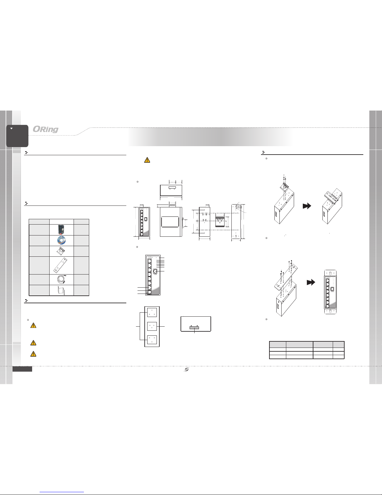
Dimension
Panel Layouts
11
1. Resetbutton
2. PWRstatus LED
3. PWR1LED
4. PWR2LED
5. R.M.status LED
6. Ringstatus LED
7. Faultyrelay indicator
8. Consoleport
9. Portspeed LED
10. Portlink LED
11. GigabitEthernet ports
Package Contents
Contents
DIN-rail Kit
CD
IGS-9080 /
IGS-9080-NP
Pictures Number
X1
X1
X1
Front View
TopPanel
The device is shippedwith the followingitems. If anyof these itemsis
missing ordamaged, please contactyour customer servicerepresentative for
assistance.
GIGABIT
INDUSTRIAL
SWITCH
Industrial Managed Gigabit Switch
QIG
Console Cable
X1
X1
X1
Wall-mountKit
10
Rear View
121
1. Wall-mountscrew holes
2. Din-railscrew holes
1. Terminalblocks: PWR1, PWR2
(12-48V DC),Relay
1
Installation
Step 1:
Step 2:
Slant the switch and screwthe Din-railkit onto theback of theswitch, right in
the middle of the back panel.
Slide theswitch ontoa DIN-rail fromthe Din-rail kitand make surethe switch
clicks intothe rail firmly.
DIN-rail Installation
Step 1:
Step 2:
Step 3:
Screw the wall-mountkit onto the rear panel ofthe switch. A total of six
screws are required, as shown below.
Use the switch,with wall mount plates attached, as a guide to mark the
correct locations of the four screws.
Insert a screwhead through the large parts ofthe keyhole-shaped apertures,
and then slidethe switch downwards. Tighten thescrews for added stability.
Wall-mounting
IGS-9080 Series
QIG
IGS-9080
1907-2-29-IGS9080-1.0
Circuit Overloading:Consideration should begiven to theconnection of the
equipment tothe supply circuitand the effectthat overloading ofthe circuits mighthave
on overcurrentprotection and supplywiring. Appropriateconsideration of equipment
nameplate ratingsshould be used when addressingthis concern.
9
Network Connection
The switchprovides standard Ethernetports. According tothe link type,the switch uses
CAT3,4,5,5e UTP cables to connect to any other network devices (PCs, servers,
switches, routers, or hubs). Please refer to the following table for cable
specifications.
Cable Typesand Specifications:
Cable Type Max. Length Conne ctor
10BASE-T Cat. 3, 4,5 100-ohm UTP 100m (328 ft) RJ-45
100BASE-TX Cat.5 100-ohmUTP UTP100 m(328 ft) RJ-45
1000BASE- T Cat. 5 /Cat. 5e 100-ohm UTP UTP100 m (328 ft) RJ-4 5
54.3
32.2
45.0
14.0
40.0
50.0
25.3
33.6
12.5
54.3
145.1
108.5
32.0
32.2
116.0
18.0 18.15
51.0
209.3
7.35
187.4
R2.5
R3.95
46.0
IGS-9080
PWR
PWR1
PWR2
R.M
Ring
Fault
10/100/
1000T
G3
G4
G1
G2
G7
G8
G5
G6
Reset
8
2
3
4
5
6
7
1
IGS-9080
PWR
PWR1
PWR2
R.M
Ring
Fault
10/100/
1000T
G3
G4
G1
G2
G7
G8
G5
G6
Reset
Page 2
QIG
Quick InstallationGuide
PRINTED ON RECYCLED PAPER
Version 1.0
Quick Installation Guide
Resetting
Toreboot the switch,press the button for2-3 seconds.
Torestore the switchconfigurations back tothe factory defaults,press the buttonfor 5 seconds.
Reset
Reset
Specifications
GIGABIT
INDUSTRIAL
SWITCH
Industrial Managed Gigabit Switch
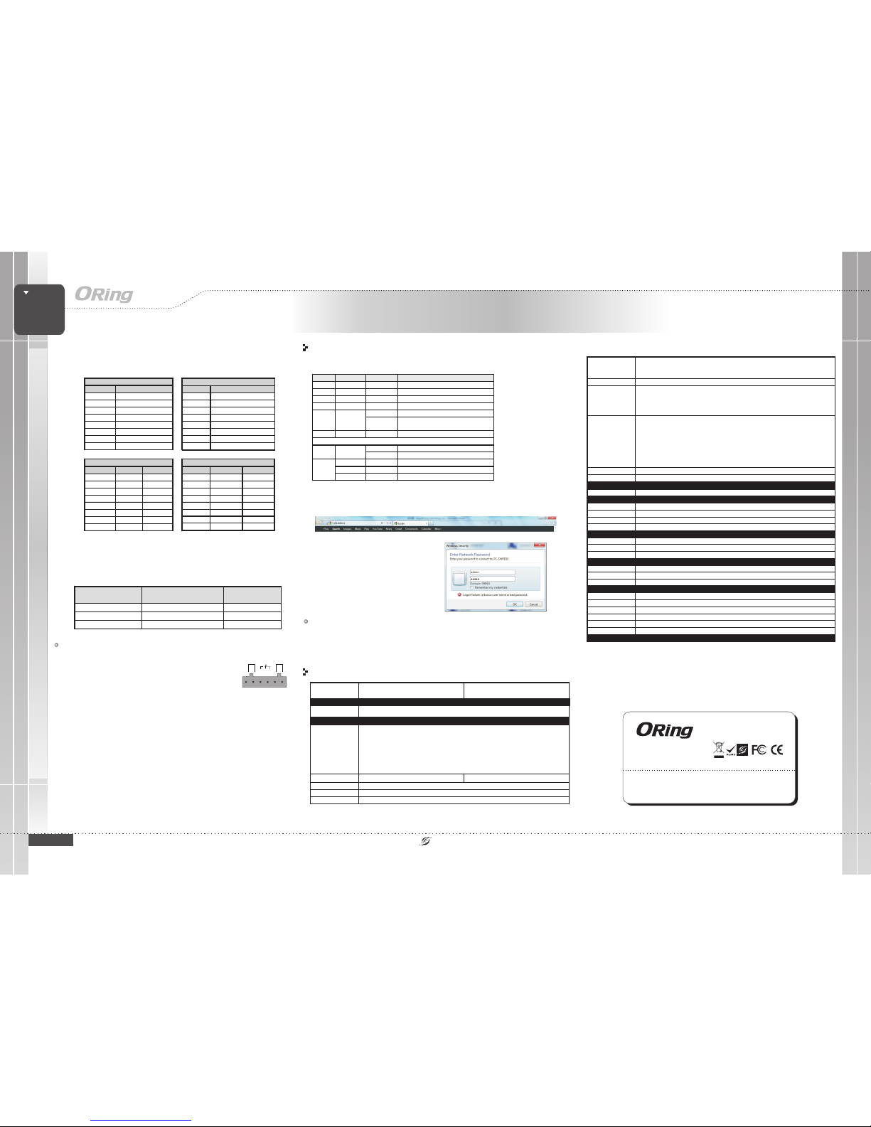
For pinassignments for differenttypes of cables,please refer tothe following
tables.
Note: “+”and “-” signsrepresent the polarityof the wiresthat make upeach
wire pair.
Toconnect the consoleport to anexternal management device,you need anRJ-45 to
DB-9 cable,which is alsosupplied in thepackage. Below isthe console portpin
assignment information.
Console PortPin Definition
PC (male) pi n assignment
RS-232 with DB9 (female) pin
assignment (RJ45-D B9 cable)
RJ45 pin as signment
PIN#2RxD PIN#2RxD PIN#2RxD
PIN#3TxD PIN#3TxD PIN#3TxD
PIN#5GND PIN#5 GND PIN#5GND
Wiring
The switch supports dual redundant power supplies, Power Supply1
(PWR1) and Power Supply2 (PWR2). Theconnections for PWR1,
PWR2 andthe RELAYare located onthe terminal block.
Insert the negative/positive wires into the V-/V+ terminals,
respectively.
To keep the DC wires from pulling loose, use a small flatblade screwdriverto tighten thewire-clamp screws onthe front ofthe
terminal blockconnector.
STEP 1:
STEP 2:
PWR-1PWR-2
1A@24V
V2-V2+ V1-V1+
Fault
Power inputs
The twosets of relaycontacts of the6-pin terminal blockconnector are usedto detect userconfigured events.The two wiresattached to thefault contacts forman open circuitwhen a
user-configured whenan event istriggered. If auser-configured event doesnot occur,the
fault circuitremains closed.
Relay contact
Grounding andwire routing helplimit the effectsof noise dueto electromagnetic
interference (EMI).Run the groundconnection from theground screws tothe grounding
surface priorto connecting devices.
Grounding
Configurations
After installingthe switch, thegreen power LEDshould turn on.Please refer tothe
following tabletfor LED indication.
1. Launchthe Internet Explorerand type inIP address ofthe switch.The default staticIP address is
192.168.10.1
2. Login with defaultuser name andpassword
(both are ). After loggingin, you should
see the following screen. For more information
on configurations, please referto the user
manual. Forinformation on operatingthe switch
using ORing’sOpen-Vision management utility,
please goto ORing website.
admin
Follow thesteps to setup the switch:
ORingSwitchModel
IGS-9080
PhysicalPorts
Technology
EthernetStandards
IEEE802.3 for 10Base-T
IEEE802.3u for 100Base-TX
IEEE802.3ab for 1000Base-T
IEEE802.3x for Flowcontrol
IEEE802.1Q for VLANTagging
IEEE802.1w for RSTP(Rapid Spanning TreeProtocol
IEEE802.1s for MSTP(Multiple Spanning TreeProtocol)
IEEE802.1x for Authentication
IEEE802.1AB for LLDP(Link Layer DiscoveryProtocol)
IEEE1588v2 clock synchronization
IEEE802.3ad for LACP(Link Aggregation ControlProtocol)
IEEE802.1p for COS(Class of service)
Power
RedundantInput power
Powerconsumption(Typ.)
DualDC inputs. 12-48VDCon 6-pin terminalblock
10.92watts
Overloadcurrent protection
Present
PhysicalCharacteristic
Enclosure
IP-30
Dimension(WxDxH)
54.1(W)x106.1(D)x145.4(H)mm (2.13x4.18x5.72 inch.)
10/100/1000Base-T(X)Ports
inRJ45 Auto MDI/MDIX
MACTable
8K
RS-232Serial Console Port
PriorityQueues
8
Processing
Store-and-Forward
SwitchProperties
Switchlatency: 7 us
Switchbandwidth: 16Gbps
Max.Number of AvailableVLANs: 256
IGMPmulticast groups: 128for each VLAN
Portrate limiting: UserDefine
SecurityFeatures
DeviceBinding security feature
Enable/disableports, MAC basedport security
Portbased network accesscontrol (802.1x)
VLAN(802.1q) to segregateand secure networktraffic
Radiuscentralized password management
SNMPv3encrypted authentication andaccess security
Https/ SSH enhancenetwork security
SoftwareFeatures
STP/RSTP/MSTP(IEEE 802.1D/w/s)
RedundantRing (O-Ring) withrecovery time lessthan 30ms over250 units
TOS/Diffservsupported
Qualityof Service (802.1p)for real-time traffic
VLAN(802.1Q) with VLANtagging and GVRPsupported
IGMPSnooping for multicastfiltering
IP-basedbandwidth management
Application-basedQoS management
DOS/DDOSauto prevention
Portconfiguration, status, statistics,monitoring, security
DHCPServer / Clientsupport
SMTPClient
ModbusTCP
NetworkRedundancy
O-Ring,Open-Ring, O-chain, MRP,MSTP (RSTP/STPcompatible)
RS-232in RJ45 connectorwith console cable. Baud ratesetting: 115200bps, 8,N, 1
Weight (g)
776g
8
Jumboframe
Upto 9.6K Bytes
Weight (g)
710g 740g722g 735g 735g 740g
Environmental
-40to85C(-40to185F)
oo
StorageTemperature
-40to70C(-40to158F)
oo
OperatingTemperature
5%to 95% Non-condensingOperatingHumidity
RegulatoryApprovals
FCCPart 15, CISPR(EN55022) class AEMI
EN61000-4-2(ESD), EN61000-4-3 (RS),EN61000-4-4 (EFT), EN61000-4-5(Surge),EN61000-4-6 (CS), EN61000-4-8,EN61000-4-11
EMS
IEC60068-2-27Shock
IEC60068-2-32
IEC60068-2-6Vibration
EN60950-1
Safety
FreeFall
Warranty
5years
LED Color Statu s Description
PWR Green On D Cpower on
PWR1 Green On DC powermodule 1activat ed
PWR2 Green On DC powermodule 2activat ed
R.M Green On RingMaster
On R ingenabled
Ring Green
Blinking
Ringstructure isbroken(i.e. partof theringis
disconnected)
Fault Amber On Faulty relay(powerfailure orport disconnected)
10/100/1000Base-T(X) Gigabit Ethernet ports
On P ortlink UP
LNK/ACT Green
Blinking Data transmitted
Green On Port linka t1000Mbps
Amber On Po rtlink at10/100 Mbps
Speed
Green/Amber Off Port linkat 10Mbps
ORing IndustrialNetworking Corp.
Copyright© 2014 ORing
All rightsreserved.
TEL: +886-2-2218-1066
FAX:+886-2-2218-1014
Website: www.oring-networking.com
E-mail: [email protected]
10/100Base-T(X)MDI/MDI-X
PinNu m ber MDI port MD I-Xport
1TD+(transmit)RD+(receive)
2TD-(transmit)RD-(receive)
3RD+(receive)TD+(transmit)
4NotusedNotused
5NotusedNotused
6 RD-(re ceive) TD-(transmit)
7NotusedNotused
8NotusedNotused
1000Base-TMDI/MDI-X
PinNumber MDI port MDI-X port
1 BI_DA+ BI_DB+
2 BI_DA- BI_DB-
3 BI_DB+ BI_DA+
4 BI_DC+ BI_DD+
5BI_DC-BI_DD-
6 BI_DB- BI_DA-
7 BI_DD+ BI_DC+
8 BI_DD- BI_DC-
1000Base-T RJ-45 Port
PinNumber Assi gnment
1BI_DA+
2BI_DA-
3BI_DB+
4BI_DC+
5 BI_DC-
6BI_DB-
7BI_DD+
8 BI_DD-
10/100 Base- T(X) RJ-45 Po rt
PinNumber Assignmen ts
1TD+
2TD-
3 RD+
4 Not used
5 Not used
6RD-
7 Not used
8 Not used
IGS-9080-NP
IEEE1588v2 cloclk
synchronization
supported
Notsupported
FaultContact
Relay
Relayoutput to carrycapacity of 1Aat 24VDC
ReversePolarityProtection
Present
IGS-9080 Series
QIG
IGS-9080
 Loading...