

Page 1
P1 P2 Fault
3
4
10/100/1000T
1
2
5
Practical Operation
Features
The GigabitPoE Ethernet switch is an unmanaged PoEEthernet switch with P.S.E.
function. The switch supports Power over Ethernet, a system totransmit electrical
power,along with data,to remote devicesover standard twisted-pair cable in an
Ethernet network. The switch has 4X10/100/1000Base-T(X) P.S.E. (Power
Sourcing Equipment) ports. P.S.E. is a device(switch or hub for instance) that
will providepower in aPoE setup. The wide operating temperature range from
-40 C to70 C cansatisfy most ofoperating environment. Therefore, the switchis one
of themost reliable choices for PoE Ethernet application.
oo
Introduction Specifications
Interface
Physical Ports
Technology
Ethernet Standards
LED Indicators
Green: PowerLED x2Power indicator
10/100/1000Base-T(X)Port
in RJ45Auto MDI/MDIX
4x10/100/1000Base-T(X) P.S.E&
1x10/100/1000Base-T(X)
1
IEEE 802.3for 10Base-T
IEEE 802.3ufor 100Base-TX
IEEE 802.3abfor 1000Base-T
IEEE 802.3xfor Flow control
IEEE 802.3atPoE specification (upto 30 Wattsper portfor P.S.E.)
MAC Table
2048 MACaddresses
Environmental
-40to85C(-40to185F)
oo
Storage Temperature
Operating Temperature
5% to95% Non-condensingOperating Humidity
Regulatory Approvals
FCC Part15, CISPR (EN55022)class AEMI
EN61000-4-2 (ESD),EN61000-4-3 (RS), EN61000-4-4(EFT), EN61000-4-5 (Surge),
EN61000-4-6 (CS),EN61000-4-8, EN61000-4-11
EMS
IEC60068-2-27Shock
IEC60068-2-32
IEC60068-2-6Vibration
Free Fall
Warranty
5 years
-40to70C(-40to158F)
oo
Amber:IndicatePWR1orPWR2failure
Faultindicator
Fault Contact
Relay
Relayoutput to carry capacityof 1A at24 VDC
Power
Redundant Inputpower
Power consumption(Typ.)
6.1 Watts(Power devicenot included)
Overload currentprotection
Reversepolarity protection
Present
Not Present
Physical Characteristic
Enclosure
IP-30
Dimension(WxDxH)
Weight (g)
407g
Dual DCinputs 50VDC on6-pin terminal block
26.1(W)x94.9(D)x144.3(H) mm(1.03x3.74x5.68inch.)
10/100/1000Base-T(X)
ndicator
RJ45
portandPoEi
Green onthe left forport Link/Act.
Green onthe right forPoE power injected.
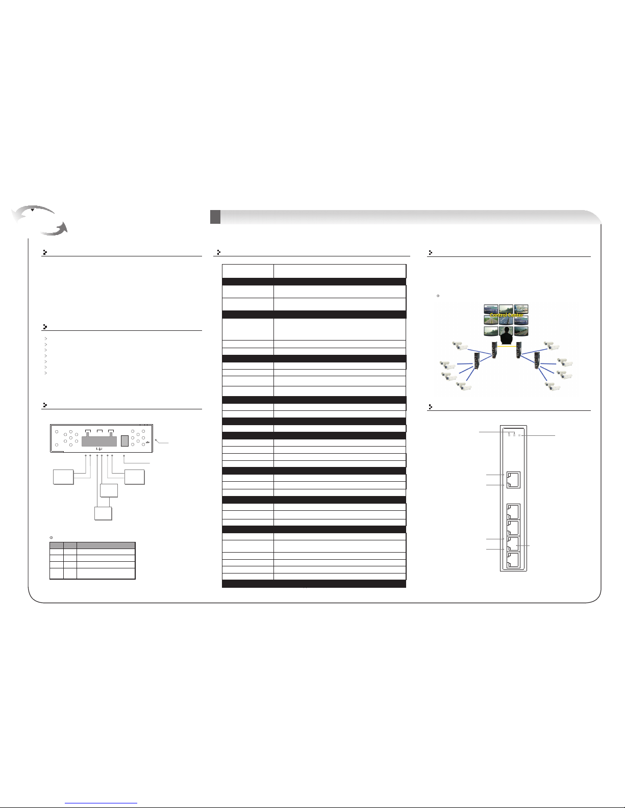
The switchcan be usedin connecting severalPoE P.D.Ethernet devices like IPCamera or other Ethernet devices. In addition, thereare two different power inputs
at terminalblock to avoid interruption caused by power down. When the primary
DC power input fails,the backup powerinput will takeover immediately toguarantee a
non-stop operation.
EN60950-1Safety
Provide 4x10/100/1000Base-T(X) PoE(P.S.E.) ports
Support P.S.E. compliant withIEEE 802.3at standard up to 30 Watts per port
Support auto-negotiationand auto-MDI/MDI-X
Support storeand forward transmission
Support flow control
Rigid IP-30housing design
DIN-Rail andwall mounting enabled
Power Connection Guide
Frame Ground
PWR-1PWR-2
V2-V2+ V1-V1+
G
1A@24V DC50-57V
Power
Supply
50 VDC
V+
V-
Warning
Device
GND+24V
V+
V-
DIP Switch Select for
PowerAlarm Relay Output
Power
Supply
50 VDC
Power
Supply
DIP-2
OFF
OFF
ON
DIP-1
Power failurerelay alarm disabled
PWR-1 failure, alarm enabledrelay
PWR-2 failure, alarm enabledrelay
DIP Switch Function
OFF
ON
OFF
Description
DIP-Switch
Power-1failedwarning:(ON)enable,(OFF)disableDIP-Switch 1
Power-2failedwarning:(ON)enable,(OFF)disable
DIP-Switch 2
Practical Operation
PowerFault LED
PowerLED
GigabitLAN Port
Green:PoE power injected
Green:Link/Act
ON
PWR-1 orPWR-2 failure,
alarm enabledrelay
ON
10/100/1000Base-T(X)Port
with P.S.E.
4
Processing
Store-and-Forward
Connections ofEthernet devices
10/100/1000Base-T(X)
ndicator
RJ45
port i
Green forport Link/Act.
Amer forduplex indicator.
Amber:Duplex indicator
Green:Link/Act
1907-2-01-PGSWD41GTA0
GIGABIT
INDUSTRIAL
SWITCH
Quick Install Guide
Version 1.0
Industrial 5-port Umanaged Gigabit PoE Switch
Page 2

Accessory
Communication Connections
1000Base-T Ethernet Connection
RJ45 (8-pin, MDI) Port Pinouts
18
Pin MDI
1
2
3
4
5
6
7
8
BI_DA+
BI_DABI_DB+
BI_DC+
BI_DCBI_DBBI_DD+
BI_DD-
RJ45 (8-pin, MDI-X) Port Pinouts
18
RJ45 (8-pin) to RJ45 (8-Pin)Straight-Through Cable Wiring
RJ45 PlugPin1
Pin
Straight-Through Cable
Switch Port
RJ-45
Connector
Tx+
TxRx+
Rx-
3
6
1
2
NIC Port
RJ-45
Connector
Rx+
RxTx+
Tx-
3
6
1
2
RJ45 (8-pin) to RJ45 (8-Pin)Cross-Over Cable Wiring
RJ45 PlugPin1
Cross-Over Cable
Switch Port
(NIC Port)
RJ-45
Connector
Tx+
TxRx+
Rx-
3
6
1
2
RJ-45
Connector
Rx+
RxTx+
Tx-
1
2
3
6
Switch Port
(NIC Port)
(Rx+)
(Rx-)
(Tx+)
(Tx-)
(Tx+)
(Tx-)
(Rx+)
(Rx-)
Pin MDI-X
1
2
3
4
5
6
7
8
BI_DB+
BI_DBBI_DA+
BI_DD+
BI_DDBI_DABI_DC+
BI_DC-
Pin
Installation
DIN-Rail Install Step Wall-mounted Install Step
10/100Base-T(X) Ethernet Connection
Dust Cover(RJ-45)
2
QIG
6
Round Screw(M3 X3)
3
Wall-mounted kit(for Slim Type)
4
25mm DIN-Railkit
5
6-Pin Terminal block
1
1
X1,2X5,3X8,X1X2,
4x10/100/1000T
P.S.E.&
1x10/100/1000T
Interface Model Description Accessory
Industrial 5-portslim type unmanagedGigabit PoE
Ethernet switchwith 4x10/100/1000Base-T(X) P.S.E.
and 1x10/100/1000Base-T(X)
6
4
5
X1,
Packing list
Pin Definition
10/100Base-T(X) PoE P.S.E.
Port
RJ45 Pin Definition
PinNo.
TD+with PoE Powerinput +
#1
Description
#2
#3
#6
TD-with PoE Powerinput +
RD+with PoE Powerinput -
RD-with PoE Powerinput -
1000Base-T PoE P.S.E. Port
RJ45 Pin Definition
PinNo.
BI_DA+with PoE Powerinput +
#1
Description
#2
#3
#4
BI_DA-with PoE Powerinput +
BI_DB+with PoE Powerinput -
BI_DC
+
BI_DC-
#5
#6
#7
#8
BI_DB-with PoE Powerinput -
BI_DD+
BI_DD-
Quick Installation Guide
GIGABIT
INDUSTRIAL
SWITCH
Quick Install Guide
Version 1.0
Industrial 5-port Umanaged Gigabit Switch
 Loading...