

Page 1
Quick InstallationGuide
Version 1.0
Quick Installation Guide
Introduction
PRINTED ON RECYCLED PAPER
QIG
IES-180-L
1907-2-29-IES180L-1.0
IES-180-L isan unmanaged Ethernetswitch with eight10/100Base-T(X)
ports in a compact form factor. The easy-to-install switch comeswith rigid
IP-30 housingand can operatein harsh environments. The wide operating
temperature rangefrom -20 C to60 C ensures theswitch can operatereliably
in extremeweather conditions.
oo
Package Contents
Installation
The device is shippedwith the followingitems. If anyof these itemsis
missing ordamaged, please contactyour customer servicerepresentative for
assistance.
Preparation
Before youbegin installing theswitch, make sureyou have allof the package
contents available.
Elevated OperatingAmbient:
ReducedAir Flow:
Mechanical Loading:
Circuit Overloading:
If installed in a closed cabinet, theoperating
ambient temperatureof the rackenvironment may begreater than roomambient.
Therefore, considerationshould be givento installing theequipment in an
environment compatiblewith the maximumambient temperature (Tma)specified
by themanufacturer.
Installation of the equipment should be such that the
amount of air flow required for safe operation of the equipment is not
compromised.
Mounting of the equipment in the d should be
such that a hazardous condition is not achieved due to uneven mechanical
loading.
Consideration shouldbe given tothe connection ofthe
equipment tothe supply circuitand the effectthat overloading ofthe circuits
might haveon overcurrent protectionand supply wiring.Appropriate
consideration ofequipment nameplate ratingsshould be used when addressing
this concern.
in-rail
Safety & Warnings
Contents
Wall-mountKit
DIN-rail Kit
IES-180-L
Pictures Number
X2
X1
QIG
X1
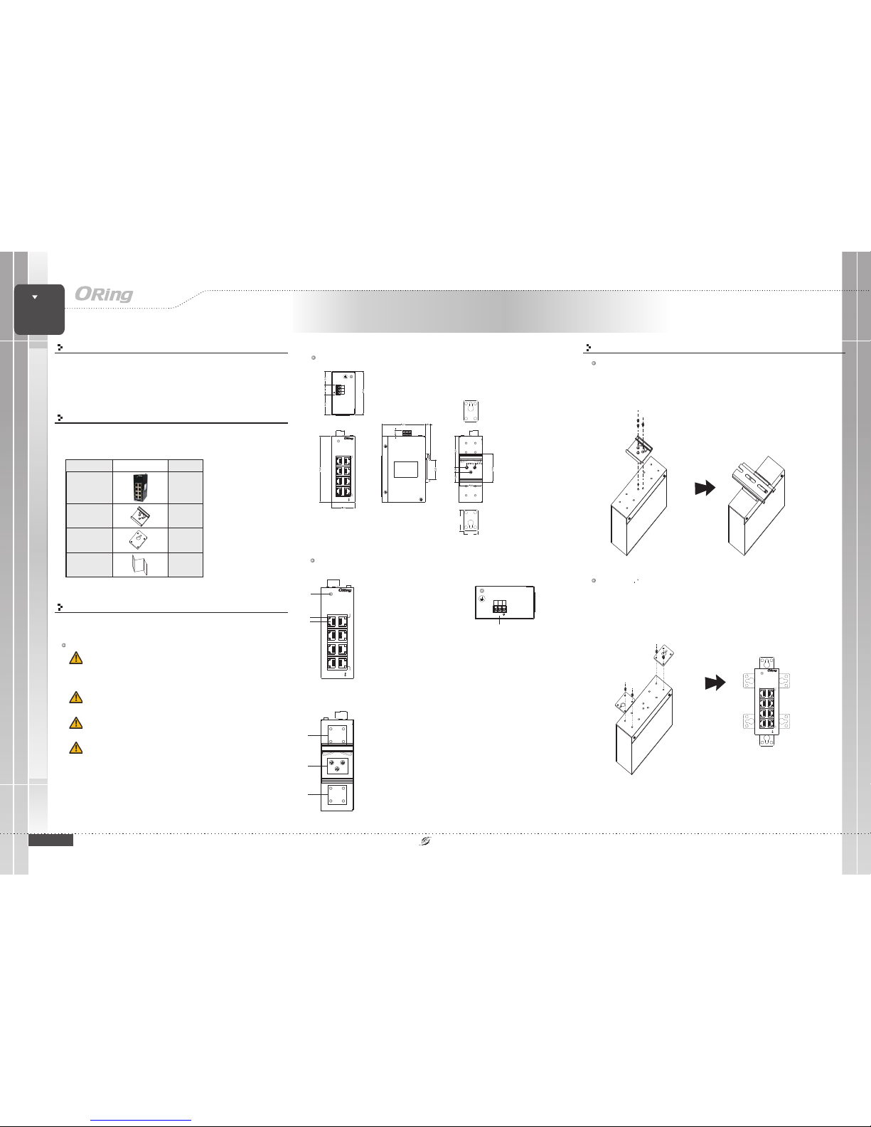
Dimension (Unit: mm)
Panel Layouts
Front Panel
1. PWRLED
2. Link/Actindicator for LANport
3. LANport
IES-180-L
X1
1
3
2
TopPanel
1. Terminalblock
Real Panel
1
1. Wall-mountscrew holes
2. Din-railscrew holes
Step 1:
Step 2:
Slant the switch and screwthe Din-railkit onto theback of theswitch, right in the
middle of the back panel.
Slide theswitch ontoa DIN-rail fromthe Din-rail kitand make surethe switch clicksinto
the railfirmly.
DIN-rail Installation
Step 1:
Step 2:
Step 3:
Screw the twopieces of wall-mount kits onto bothsides of the switch. A
total of eightscrews are required, as shown below.
Use the switch,with wall mount plates attached, as a guide to mark the correct
locations of screws.
Insert screw throughthe large parts of the keyhole-shapedapertures, and then slide
the switch downwards.Tighten the four screws foradded stability.
wall-mount
Wall-mounting
SWITCH
INDUSTRIAL
Industrial Unmanaged Switch
1
IES-180-L
P2
P4
P6
P1
P3
P5
V+ V-
DC10~30V
P8P7
PWR
10/100TX
LNK/ACT
SPEED
100M
10M
IES-180-L
P2
P4
P6
P1
P3
P5
P8P7
PWR
10/100TX
LNK/ACT
SPEED
100M
10M
25.00
37.00
V+ V-
DC10~30V
IES-180-L
P2
P4
P6
P1
P3
P5
P8P7
PWR
10/100TX
LNK/ACT
SPEED
100M
10M
IES-180-L
P2
P4
P6
P1
P3
P5
P8P7
PWR
10/100TX
LNK/ACT
SPEED
100M
10M
1
2
IES-180-L
P2
P4
P6
P1
P3
P5
P8P7
PWR
10/100TX
LNK/ACT
SPEED
100M
10M
IES-180-L
P2
P4
P6
P1
P3
P5
P8P7
PWR
10/100TX
LNK/ACT
SPEED
100M
10M
Page 2
QIG
Quick InstallationGuide
PRINTED ON RECYCLED PAPER
Quick Installation Guide
ORing IndustrialNetworking Corp.
Copyright© 2015 ORing
All rightsreserved.
TEL: +886-2-2218-1066
FAX:+886-2-2218-1014
Website: www.oring-networking.com
E-mail: [email protected]
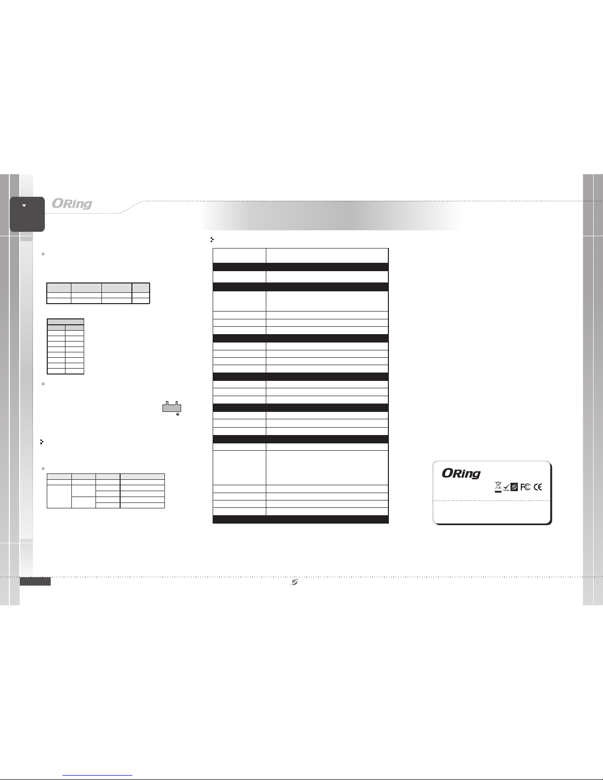
The switch providesa 10~30 VDC voltagepower input ona 3pin terminal block. Follow the stepsto connect thepower.
Insert the negative/positive wires into the V-/V+
terminals, respectively.
To keep the DC wires from pulling loose, use a small
flat-blade screwdriver to tighten the wire-clamp screws onthe
front ofthe terminal blockconnector.
STEP 1:
STEP 2:
Version 1.0
QIG
Configurations
After installing the switchand connecting cables,start the switchby
turning on power. The green power LEDs should turn on.and
LED indication table
Specifications
QIG
Wiring
ORing SwitchModel
IES-180-L
10/100Base-T(X)Ports in
RJ45 AutoMDI/MDIX
8
Physical Ports
Technology
Ethernet Standards
IEEE 802.3for 10Base-T
IEEE 802.3ufor 100Base-TX
IEEE 802.3xfor Flow control
Power
Input power
Power consumption(Typ.)
10~30 VDCvoltage power inputon 3-pin terminalblock
1.65 Watts
Overload currentprotection
Reverse polarityprotection
Present
Present
Physical Characteristic
Enclosure
IP-30
Dimension(WxDxH)
41(W)x75(D)x115(H)mm(1.61x2.95x4.53inch)
Weight (g )
Environmental
-40to85C(-40to185F)
oo
Storage Temperature
Operating Temperature
5% to95% Non-condensingOperating Humidity
Regulatory Approvals
FCC Part15, CISPR (EN55022)class AEMI
EN61000-4-2 (ESD),
EN61000-4-3 (RS),
EN61000-4-4 (EFT),
EN61000-4-5 (Surge),
EN61000-4-6 (CS),
EN61000-4-8,
EN61000-4-11
EMS
IEC60068-2-27Shock
IEC60068-2-32
IEC60068-2-6Vibration
EN60950-1
Safety
Free Fall
Warranty
5years
Processing
Store-and-Forward
307 g
-20to60C(-4to140F)
oo
MAC Table
2048 MACaddresses
Network Connection
The devicehas standard Ethernetports. Accordingto the linktype, the switchuses CAT3,
4, 5,5e UTP cables to connect to any other network devices (PCs,servers, switches,
routers, or hubs). Please refer to the following table for cable specifications.
Cable Typesand Specifications:
Cable Type Max. Length Connector
10BASE-T Cat. 3, 4,5 100-ohm UTP 100m (328 ft) RJ-45
100BASE-TX Cat.5 100-ohm UTP UTP 100m (328 ft) RJ-45
For pinassignments for thecables, please referto the followingtable.
10/100Base-T(X) RJ-45
Pin Number Assignment
1TD+
2TD-
3RD+
4Notused
5Notused
6RD-
7Notused
8Notused
Note: “+”and “-” signs represent the polarity of the wires that
make up each wire pair.
QIG
SWITCH
INDUSTRIAL
Industrial Unmanaged Switch
Power inputs
V+ V-
LED Color Status Descripti on
PWR Green On DC powermodule activated
On Portislinked
Green
Blinking Transmitting data
On Portis runningat 100Mbps
LNK/ACT
Amber
Off Portis runningat1 0Mbps
QIG
IES-180-L
IES-180-L
Packet Buffer
448Kbits
 Loading...