

Page 1
Device
10/100 Ba se-T(X) M DI/MDI-X
Pin Number MDI port MD I-X port
1TD+(transmit)RD+(receive)
2TD-(transmit)RD-(receive)
3 RD+(recei ve) T D+(transmit)
4NotusedNotused
5NotusedNotused
6 RD-(receive) TD-(transmit)
7NotusedNotused
8NotusedNotused
10/100 Base-T(X) RJ-45
Pin Numb er Assignment
1TD+
2TD-
3RD+
4Notused
5Notused
6RD-
7Notused
8Notused
Cab le Type Max. L ength Connector
10BASE- T Cat. 3, 4, 5 100-ohm UT P 100 m ( 328 ft) RJ-4 5
100BASE-TX Cat. 5 100-ohmUTP UTP 100m (328 ft) RJ-45
Server
Quick Installation Guide
Introduction
IDS-M311
Modbus TCP and Modbus RTU/ASCII devices. The device is able to
support up to 31 RTU/ASCII devices with its serial port, thus can
effectively connect a high density of Modbus nodes to the same network.
You can use the Web configuration interface to configure multiple devices
and set up operation modes for different application
requirements. supports RS-232/422/485 and provides dual
redundant power inputs guarantee a non-stop operation.
Package Contents
The device is shipped with the following items. If any of these items is
missing or damaged, please contact your customer service representative for
assistance.
Contents
IDS-M311
CD
DIN-rail Kit
Wall-mount Kit
QIG
is a 1-port Modbus gateway which converts signals between
IDS-M311
IDS-M311
Pictures Number
X1
X1
X1
X1
X1
IDS-M311
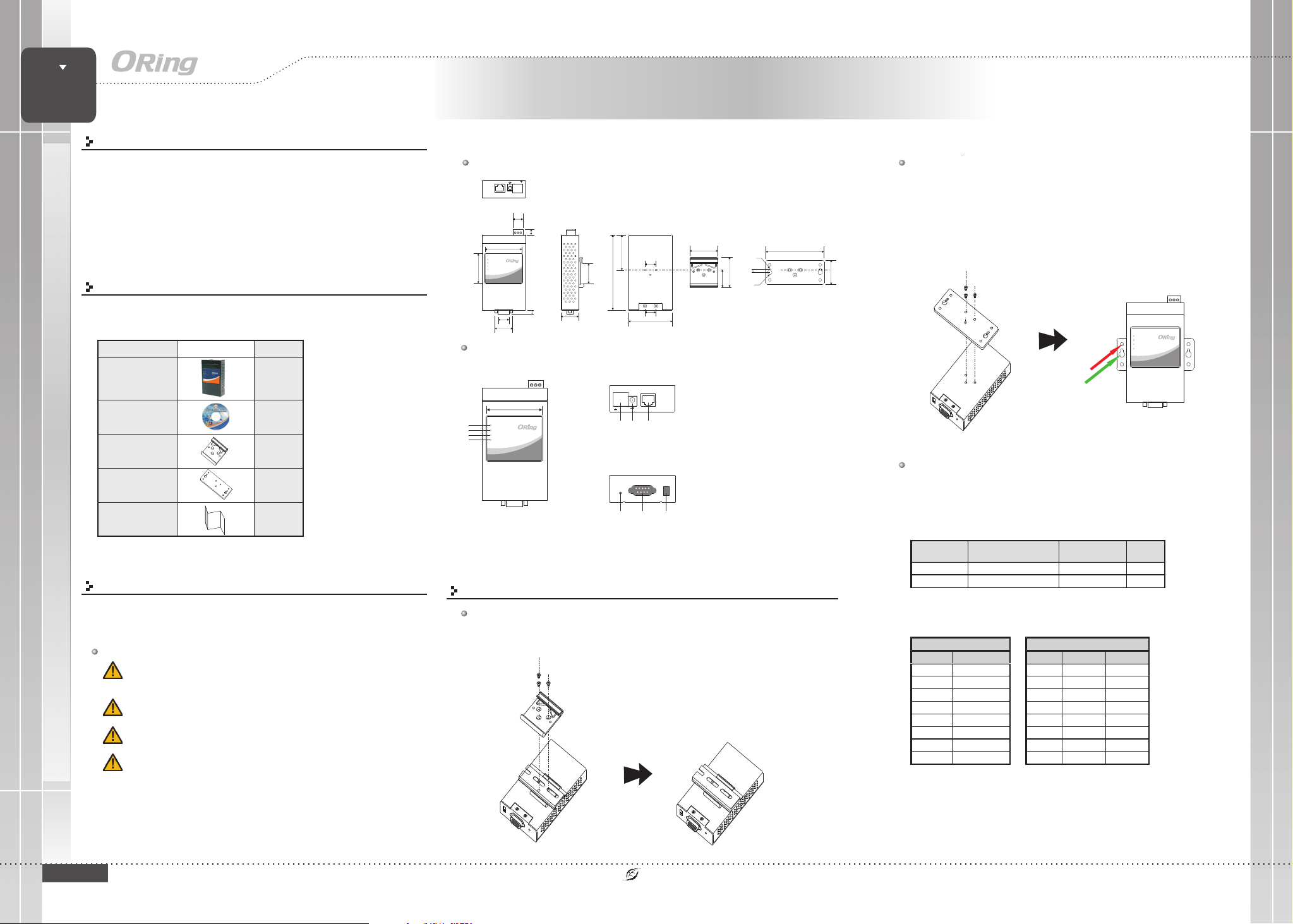
Dimension
ETH
+
GV+V-
-
PWR1
PWR2
AutoMDI/MDIX
12-48VDC
15.40
60.00
PWR1
PWR2
ETHLNK/ACT
TX/RX
48.00
17.80
30.20
Panel Layouts
Front View
PWR1
1
PWR2
2
ETH LNK/ACT
3
TX/RX
4
1. LED for PWR1
2. LED for PWR2
3. LED for 10/100Base-T(X)
Ethernet port
4. LED for serial port
9.00
IDS-M311
5.00
60.00
IDS-M311
Version 1.0
Industrial Device Server
Wall-mounting
Screw the wall-mount kit onto the rear panel of the device. A total of three
Step 1:
screws are required, as shown below.
Step 2:
Use the device, with wall mount plates attached, as a guide to mark the
correct locations of the four screws.
Step 3:
Insert screws through the round screw holes (the red arrow as below) on the
sides or through the key hole-shaped aperture (the green arrow as below) in the middle of
the plate and fasten the screw to the wall with a screwdriver.
Step 4:
58.00
123.40
18.00
18.00
72.00
33.6
29.40
45.0
R1.55
50.0
5.45
25.3
R3.50
96.00
40.00
Top Panel
12-48VDC
AutoMDI/MDIX
PWR1
PWR2
-
GV+V-
+
12 3
ETH
1. Terminal block: PWR1(12 ~ 48V DC)
2. Power jack: PWR2 (12 ~ 48V DC)
3. RJ45 Ethernet Connector
Bottom Panel
SerialPort
Reset
12
3
1. Reset button
2. Serial port
3. Termination
If the screw goes through the cross-shaped aperture, slide the device down
before tightening the screw.
PWR1
PWR2
IDS-M311
ETH LNK/ACT
TX/RX
Network Connection
The have standard Ethernet port. According to the link type, the device uses
IDS-M311
CAT 3,4,5,5e UTP cables to connect to any other network devices (PCs, servers,
switches, routers, or hubs). Please refer to the following table for cable
specifications.
Cable Types and Specifications:
Preparation
Before you begin installing the device, make sure you have all of the package
contents available and a PC with Microsoft Internet Explorer 6.0 or later, for
using web-based system management tools.
Safety & Warnings
Elevated OperatingAmbient:
the operating ambient temperature is compatible with the maximum
ambient temperature (Tma) specified by the manufacturer.
Reduced Air Flow:
of the equipment is not compromised during installation.
Mechanical Loading:
hazardous condition due to uneven mechanical loading.
Circuit Overloading:
equipment to the supply circuit andthe effect that overloading of the circuits
might have on overcurrent protection andsupply wiring. Appropriate
consideration ofequipment nameplate ratings shouldbe used when addressing
QIG
this concern.
IDS-M311
Make surethe amount of airflow required for safeoperation
Make surethe mounting of theequipment is not in a
Consideration shouldbe given to theconnection of the
If installed in a closed environment, make sure
1907-2-29-IDSM311-1.0
Installation
DIN-rail Installation
Step 1:
Slant the device and screw the Din-rail kit onto the back of the device, right in the middle of
the back panel.
Step 2:
Slide thedevice onto a DIN-rail from the Din-rail kit and make sure the device clicks into the rail
firmly.
PRINTED ON RECYCLED PAPER
For pinassignments for different typesof cables, please referto the following
tables.
Note: “+” and “-” signs representthe polarity of thewires that make upeach
wire pair.
Quick Installation Guide
Page 2
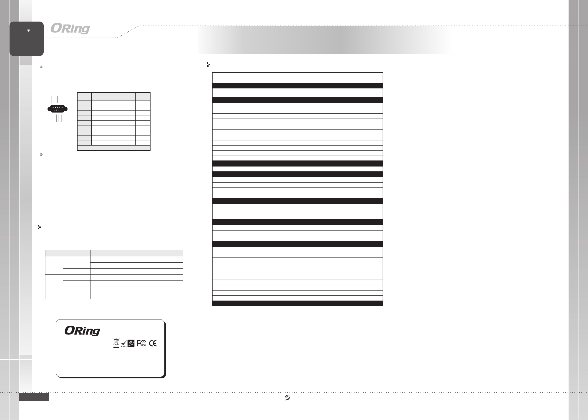
LED Color Status De scripti on
On Power mo dule 1 activ ated
Red
Blinki ng DHCP serv ers do not respond prope rly
PW1/2
Green On Power i s on and f unction normally
Green On Port runni ng at 100M bpsETH
LNK/ ACT
Amber On Port running at 10Mb ps
Red On Receiving data
TX / RX
Green On Transmit ting data
Pin #
RS-232 RS-422
RS-485
(4wire)
RS-485
(2wire)
1 DCD RXD - RXD -
2 RXD RXD + RXD +
3 TXD TXD + TXD + DATA +
4 DTR TX D - TXD - DAT A -
5 GND GND GND GND
6DSR
7RTS
8CTS
9RI
RS-232 mode act as DTE
Device
Server
Quick Installation Guide
IDS-M311
Version 1.0
Industrial Device Server
DB9 serial port
The devicecan be connected to a serial device using a DB9 cable. The DB9
connector supports RS-232 / RS-422 / RS-485 operation modes. Please refer to
the following table for the pin assignments of the DB9 connector.
12345
6789
Wiring
Grounding
Grounding andwire routing help limitthe effects of noise due to electromagnetic
interference (EMI). Run the ground connectionfrom the ground screwsto the grounding
surface prior to connecting devices.
Power inputs
The device has two sets of power inputs in the form of DC power jack and terminal.
The power input connectors are located on the top panel alongside the Ethernet
port. Follow the steps below to wire the power input on the terminal block.
Step 1: insert the negative / positive wires into the V-/V+ terminals, respectively.
Step 2: to keep the wires from pulling loose, use a small flat-blade screwdriver to
tighten the wire-clamp screws on the front of the terminal block connector.
Configurations
After installing the device, the green power LED should turn on. Please refer
to the following tablet for LED indication.
Specifications
Oring DeviceModel
Physical Ports
10/100 Base-T(X) Portsin RJ45
Auto MDI/MDIX
Serial Ports
Connector
Operation Mode
SerialBaudRate
Data Bits
Parity
Stop Bits
RS-422
RS-485 (4-wire)
RS-485 (2-wire)
Flow Control
Network Protocol
Protocol
Power
Redundant Inputpower
Power consumption(Typ.)
Overload currentprotection
Reverse polarityprotection
Physical Characteristic
Enclosure
Dimension(WxDxH)
Weigh t( g)
Environmental
Storage Temperature
Operating Temperature
Regulatory Approvals
EMS
Free Fall
Safety
Warranty
IDS-M311
1
DB9 (male)x 1
RS-232 /RS-422 / 4(2)-WireRS-485. Which can beconfigured by Webinterface
110 bpsto 115.2 Kbps
5, 6,7, 8
odd, even,none, mark, space
1, 1.5,2
TxD, RxD, RTS, CTS, DTR, DSR, DCD, RI, GNDRS-232
Tx+, Tx-,Rx+, Rx, GND
Tx+, Tx-,Rx+, Rx, GND
Data+, Data-,GND
XON/XOFF,RTS/CTS, DTR/DSR
ICMP,IP, TCP,UDP, DHCP, BOOTP,DNS, SNMP V1/V2c,HTTPS, SMTP,DDNS, PPPoE, Modbus TCP
Dual DCinputs. 12-48VDC on3-pin terminal blockand power jack
4 watts
Present
Present onterminal block
IP-30
72(W)x29.4(D)x123.4(H) mm(2.83x1.16x4.86 inch.)
294g
oo
-40to85C(-40to185F)
oo
-40to85C(-40to185F)
5% to95% Non-condensingOperating Humidity
IEC 61850-3,IEEE 1613Power Automation
FCC Part15, CISPR (EN55022)class AEMI
EN61000-4-2 (ESD)
EN61000-4-3 (RS)
EN61000-4-4 (EFT)
EN61000-4-5 (Surge)
EN61000-4-6 (CS)
EN61000-4-8
EN61000-4-11
IEC60068-2-27Shock
IEC60068-2-32
IEC60068-2-6Vibration
EN60950-1
5 years
Copyright© 2014 ORing
All rightsreserved.
ORing Industrial Networking Corp.
QIG
QIG
TEL: +886-2-2218-1066
FAX: +886-2-2218-1014
IDS-M311
Website: www.oring-networking.com
E-mail: [email protected]
PRINTED ON RECYCLED PAPER
Quick Installation Guide
 Loading...