

Page 1
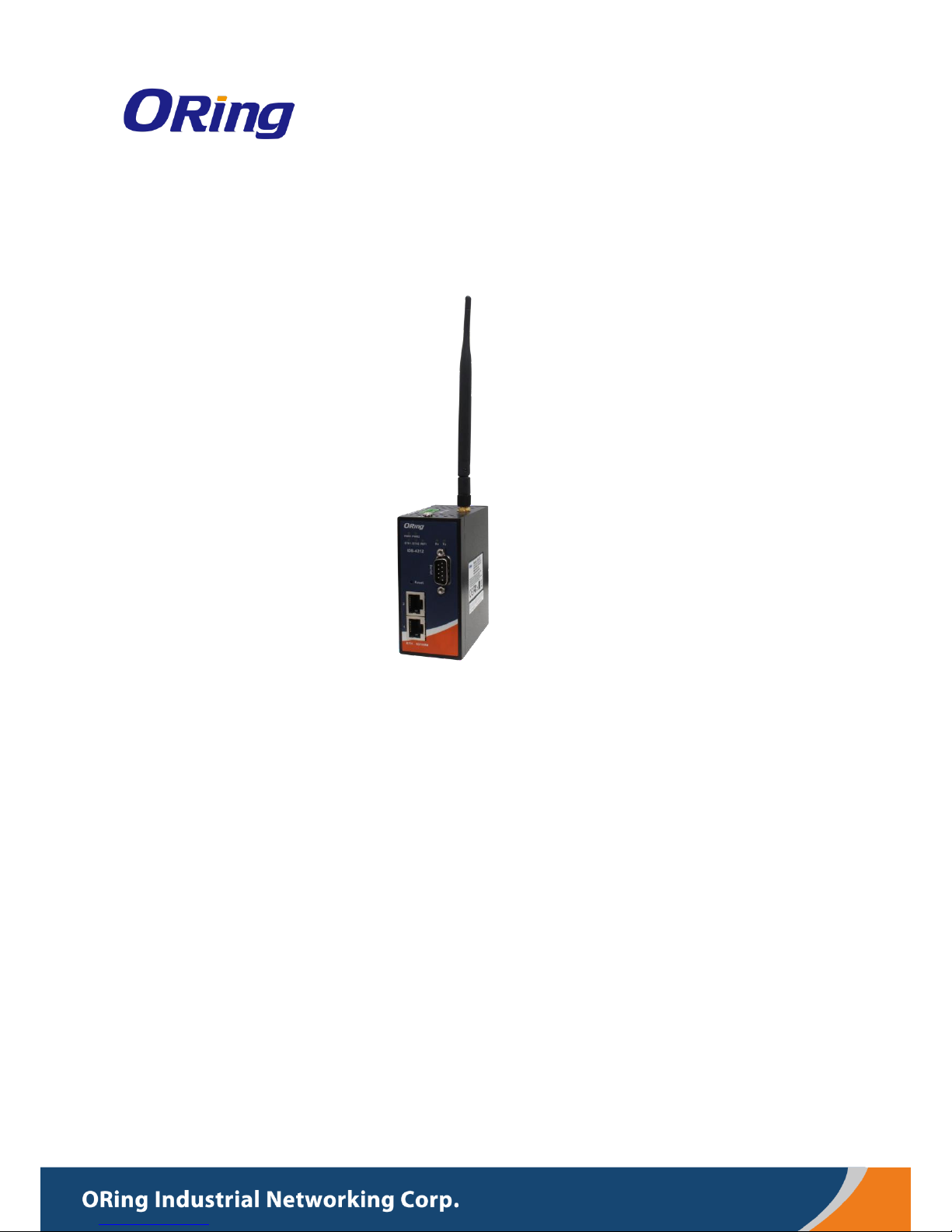
IIDDSS--44331122++
IInndduussttrriiaall DDeevviiccee SSeerrvveer
r
UUsseerr M
Maannuuaall
VVeerrssiioonn 11..00
AApprriill,, 22001177
wwwwww..oorriinngg--nneettwwoorrkkiinngg..ccoomm
Page 2

IDS-4312(+) Series User Manual
ORing Industrial Networking Corp
1
COPYRIGHT NOTICE
Copyright © 2017 ORing Industrial Networking Corp.
All rights reserved.
No part of this publication may be reproduced in any form without the prior written consent
of ORing Industrial Networking Corp.
TRADEMARKS
is a registered trademark of ORing Industrial Networking Corp.
All other trademarks belong to their respective owners.
REGULATORY COMPLIANCE STATEMENT
Product(s) associated with this publication complies/comply with all applicable regulations.
Please refer to the Technical Specifications section for more details.
WARRANTY
ORing warrants that all ORing products are free from defects in material and workmanship
for a specified warranty period from the invoice date (5 years for most products). ORing
will repair or replace products found by ORing to be defective within this warranty period,
with shipment expenses apportioned by ORing and the distributor. This warranty does not
cover product modifications or repairs done by persons other than ORing-approved
personnel, and this warranty does not apply to ORing products that are misused, abused,
improperly installed, or damaged by accidents.
Please refer to the Technical Specifications section for the actual warranty period(s) of the
product(s) associated with this publication.
DISCLAIMER
Information in this publication is intended to be accurate. ORing shall not be responsible
for its use or infringements on third-parties as a result of its use. There may occasionally
be unintentional errors on this publication. ORing reserves the right to revise the contents
of this publication without notice.
CONTACT INFORMATION
ORing Industrial Networking Corp.
3F., NO.542-2, Jhongjheng Rd., Sindian District, New Taipei City 231, Taiwan, R.O.C.
Tel: + 886 2 2218 1066 // Fax: + 886 2 2218 1014
Website: www.oringnet.com
Technical Support
E-mail: [email protected]
Sales Contact
E-mail: [email protected] (Headquarters)
[email protected] (China)
Page 3

IDS-4312(+) Series User Manual
ORing Industrial Networking Corp
2
Table of Content
Getting Started ............................................................................................... 3
1.1 About IDS-4312(+) Series ..................................................................................... 3
1.2 Software Features ................................................................ ................................ 3
1.3 Hardware Specifications ....................................................................................... 3
Hardware Overview ........................................................................................ 5
2.1 Front Panel ........................................................................................................... 5
2.1.1 Ports and Connectors ....................................................................................... 5
2.1.2 LED .................................................................................................................. 6
2.2 Top Panel ............................................................................................................. 6
2.3 Rear Panel ........................................................................................................... 7
Hardware Installation ..................................................................................... 8
3.1 DIN-rail Installation ............................................................................................... 8
3.2 Wall Mounting ....................................................................................................... 9
3.3 Wiring ................................................................................................................. 10
3.3.1 Grounding ...................................................................................................... 10
3.3.2 Redundant Power Inputs ................................................................................ 11
3.4 Connection ......................................................................................................... 11
3.4.1 Cables ............................................................................................................ 11
Management ................................................................................................. 13
4.1 DS-Tool .............................................................................................................. 13
4.1.1 Install DS-Tool ................................................................................................ 13
4.1.2 Using DS-Tool ................................................................................................ 14
4.1.3 Configure Device Servers ............................................................................... 15
4.1.4 Configure Serial Port ...................................................................................... 21
4.2 Web Management ................................................................ .............................. 30
4.2.1 System ........................................................................................................... 31
4.3 Configuration by SSH Console ............................................................................ 49
4.3.1 Connect to DS ................................................................ ................................ 49
Technical Specifications ............................................................................. 51
Page 4

IDS-4312(+) Series User Manual
ORing Industrial Networking Corp
3
Getting Started
1.1 About IDS-4312(+) Series
The IDS-4312(+) is an industrial device server with one RS-232/422/485 port and two
LAN ports designed for converting signals between serial and Ethernet networks. It also
provides 802.11 b/g/n WLAN function for wireless connectivity. The device offers standard
features of device servers such as TCP/IP interfaces and versatile operation modes
including Virtual Com, Serial Tunnel, TCP Server, TCP Client, UDP. The device also
supports Windows utility DS-Tool which allows you to configure multiple devices and set
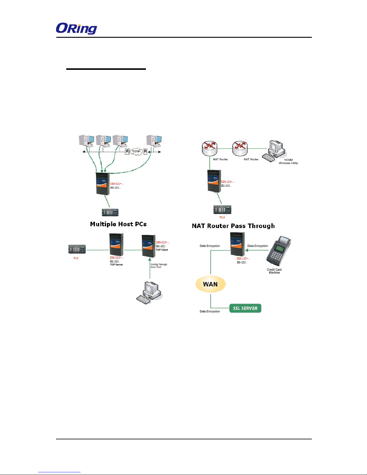
up the mappings of Virtual Com. The device can transfer data to five host PCs
simultaneously for redundancy in case of Ethernet connection breakdown or host PC
failure. Further, the device supports HTTPS, SSH, and SSL encryption to assure the
security of critical data transmission. One of the Ethernet port on the IDS-4312+ supports
IEEE802.3af-compliant PoE PD (Power Device) function, making the device ideal for
environment where cabling or power supply is difficult.
1.2 Software Features
Supports five host devices including Virtual COM, TCP Server, TCP Client modes
and four IP ranges
Supports operating modes such as Virtual Com, Serial Tunnel, TCP Server, TCP
Client, UDP
NAT-pass through support for users to manage IDS-4312 through NAT router
Ensure high levels of security with SSL data encryption, HTTPS/SSH, IP access
control and IP white list
Event warning by Syslog, Email, SNMP trap, and beeper
Configurable by Web Interface and Windows utility
Configurable by Windows utility (DS-Tool)
Various Windows OS supported: Windows NT/2000/ XP/ 2003/VISTA(32/64bit)/
Windows 7(32/64bit)
1.3 Hardware Specifications
1 x RS-232/422/485 serial ports
2 x 10/100Base-T(X) Ethernet ports (one PoE port provided by IDS-4312+)
1 x WLAN antenna connector
DIN-rail and wall-mount enabled
Redundant DC power inputs
Operating Temperature: -40 to 70oC
Page 5

IDS-4312(+) Series User Manual
ORing Industrial Networking Corp
4
Storage Temperature: -40 to 85oC
Operating Humidity: 5% to 95%, non-condensing
Casing: IP-30
Dimensions: 45 (W) x 81 (D) x 95 (H) mm
Page 6
IDS-4312(+) Series User Manual
ORing Industrial Networking Corp
5
Hardware Overview
2.1 Front Panel
2.1.1 Ports and Connectors
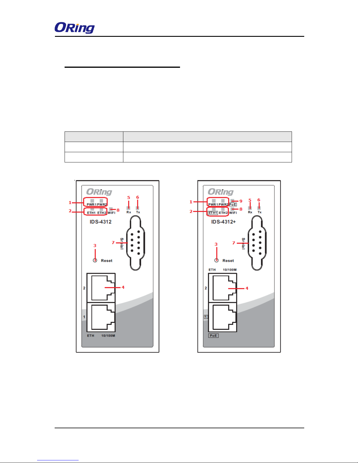
The device provides the following ports on the top panel. The Ethernet port on the device
use RJ-45 connectors
Port
Description
Copper port
2 x 10/100Base-T(X) port (one PoE port for IDS-4312+)
Serial port
1 x DB9 serial ports
IDS-4312 IDS-4312+
Page 7
IDS-4312(+) Series User Manual
ORing Industrial Networking Corp
6
2.1.2 LED
LED
Color
Status
Description
PW1/2
Green
On
Power is on and function normally
PoE
Green
On
PoE power is on and function normally
ETH
1/2
Green
On
Port running at 100Mbps
TX /
RX
Red
On
Receiving data
Green
On
Transmitting data
WLAN
Green
Blinking
Connecting to wireless networks
2.2 Top Panel
Below are the top panel components of the device:
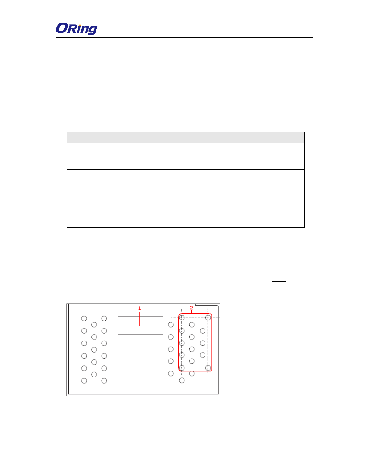
1. Terminal blocks: PWR1, PWR2, Relay
2. Ground wire. For more information on how to ground the switch, please refer to 3.3.1
Grounding.
1. Power status indicators
2. LAN port connection indicators
3. Reset button
4. Ethernet port (ETH 2 of IDS-4312+ is
PoE-enabled)
5. Serial signal transmission status
indicator
6. Serial signal reception status indicator
7. Serial port
8. LED for wireless connection status
9. PoE status indicator
1. Terminal block
2. Wall-mount screw holes
Page 8
IDS-4312(+) Series User Manual
ORing Industrial Networking Corp
7
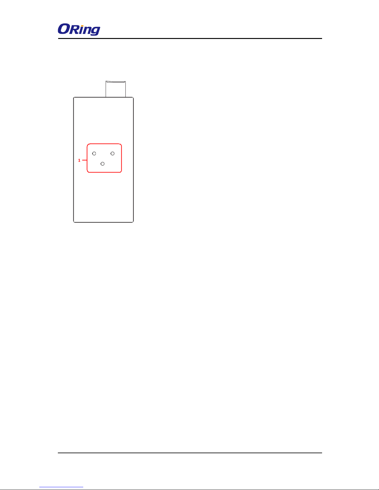
2.3 Rear Panel
1. DIN-rail screw holes
Page 9
IDS-4312(+) Series User Manual
ORing Industrial Networking Corp
8
Hardware Installation
3.1 DIN-rail Installation
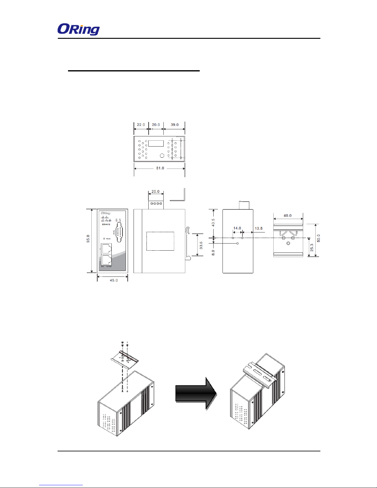
The device comes with a DIN-rail kit to allow you to fasten the device to a DIN-rail in any
environments.
DIN-rail Kit Measurement (unit = mm)
Installing the device on the DIN-rail is easy. First, screw the Din-rail kit onto the back of the
device, right in the middle of the back panel. Then slide the device onto a DIN-rail from the
Din-rail kit and make sure the device clicks into the rail firmly.
Page 10

IDS-4312(+) Series User Manual
ORing Industrial Networking Corp
9
3.2 Wall Mounting
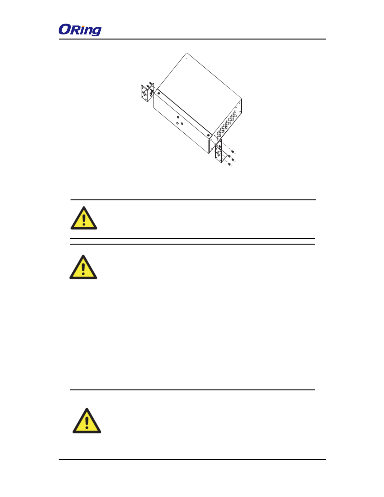
Besides Din-rail, the device can be fixed to the wall via wall mount kits, which can be
found in the package.
Wall-Mount Kit Measurement (unit = mm)
Follow the steps below to install the device to a rack.
Step 1: Install the L-shape mounting kits provided in the package to the left and right of the
device.
Step 2: With front brackets orientated in front of the rack, mount the device in the rack with
four rack-mounting screws.
Page 11
IDS-4312(+) Series User Manual
ORing Industrial Networking Corp
10
3.3 Wiring
3.3.1 Grounding
Grounding and wire routing help limit the effects of noise due to
electromagnetic interference (EMI). Run the ground connection from the
ground pin on the power module to the grounding surface prior to
connecting devices.
ATTENTION
1. Be sure to disconnect the power cord before installing and/or wiring
your devices.
2. Calculate the maximum possible current in each power wire and
common wire. Observe all electrical codes dictating the maximum
current allowable for each wire size.
3. If the current goes above the maximum ratings, the wiring could
overheat, causing serious damage to your equipment.
4. Use separate paths to route wiring for power and devices. If power
wiring and device wiring paths must cross, make sure the wires are
perpendicular at the intersection point.
5. Do not run signal or communications wiring and power wiring
through the same wire conduit. To avoid interference, wires with
different signal characteristics should be routed separately.
6. You can use the type of signal transmitted through a wire to
determine which wires should be kept separate. The rule of thumb is
that wiring sharing similar electrical characteristics can be bundled
together
7. You should separate input wiring from output wiring
8. It is advised to label the wiring to all devices in the system
WARNING
Do not disconnect modules or wires unless power has been switched off
or the area is known to be non-hazardous. The devices may only be
connected to the supply voltage shown on the type plate.
Page 12
IDS-4312(+) Series User Manual
ORing Industrial Networking Corp
11
3.3.2 Redundant Power Inputs
The device has two sets of DC power inputs on a 6-pin terminal block located on top of the
device. Follow the steps below to wire the power input on the terminal block.
Step 1: insert the negative/positive wires into the V-/V+ terminals, respectively.
Step 2: to keep the wires from pulling loose, use a small flat-blade screwdriver to tighten
the wire-clamp screws on the front of the terminal block connector.
3.4 Connection
3.4.1 Cables
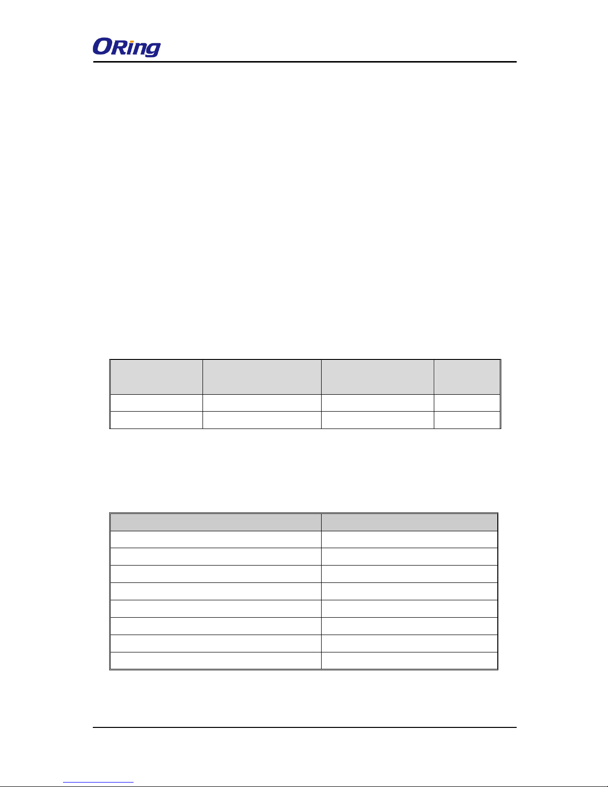
10/100BASE-T(X) Pin Assignments
The device has two standard Ethernet ports. According to the link type, the device uses
CAT 3, 4, 5,5e UTP cables to connect to any other network devices (PCs, servers,
switches, routers, or hubs). Please refer to the following table for cable specifications.
Cable Types and Specifications:
Cable
Type
Max. Length
Connect
or
10BASE-T
Cat. 3, 4, 5 100-ohm
UTP 100 m (328 ft)
RJ-45
100BASE-TX
Cat. 5 100-ohm UTP
UTP 100 m (328 ft)
RJ-45
With 10/100Base-T(X) cables, pins 1 and 2 are used for transmitting data, and pins 3 and
6 are used for receiving data.
10/100 Base-T(X) RJ-45 Pin Assignments :
Pin Number
Assignment
1
TD+
2
TD-
3
RD+
4
Not used
5
Not used
6
RD-
7
Not used
8
Not used
The device also supports auto MDI/MDI-X operation. You can use a cable to connect the
Page 13
IDS-4312(+) Series User Manual
ORing Industrial Networking Corp
12
device to a PC. The table below shows the 10/100Base-T(X) MDI and MDI-X port pin
outs.
10/100 Base-T(X) MDI/MDI-X Pin Assignments:
Pin Number
MDI port
MDI-X port
1
TD+(transmit)
RD+(receive)
2
TD-(transmit)
RD-(receive)
3
RD+(receive)
TD+(transmit)
4
Not used
Not used
5
Not used
Not used
6
RD-(receive)
TD-(transmit)
7
Not used
Not used
8
Not used
Not used
Note: “+” and “-” signs represent the polarity of the wires that make up each wire pair.
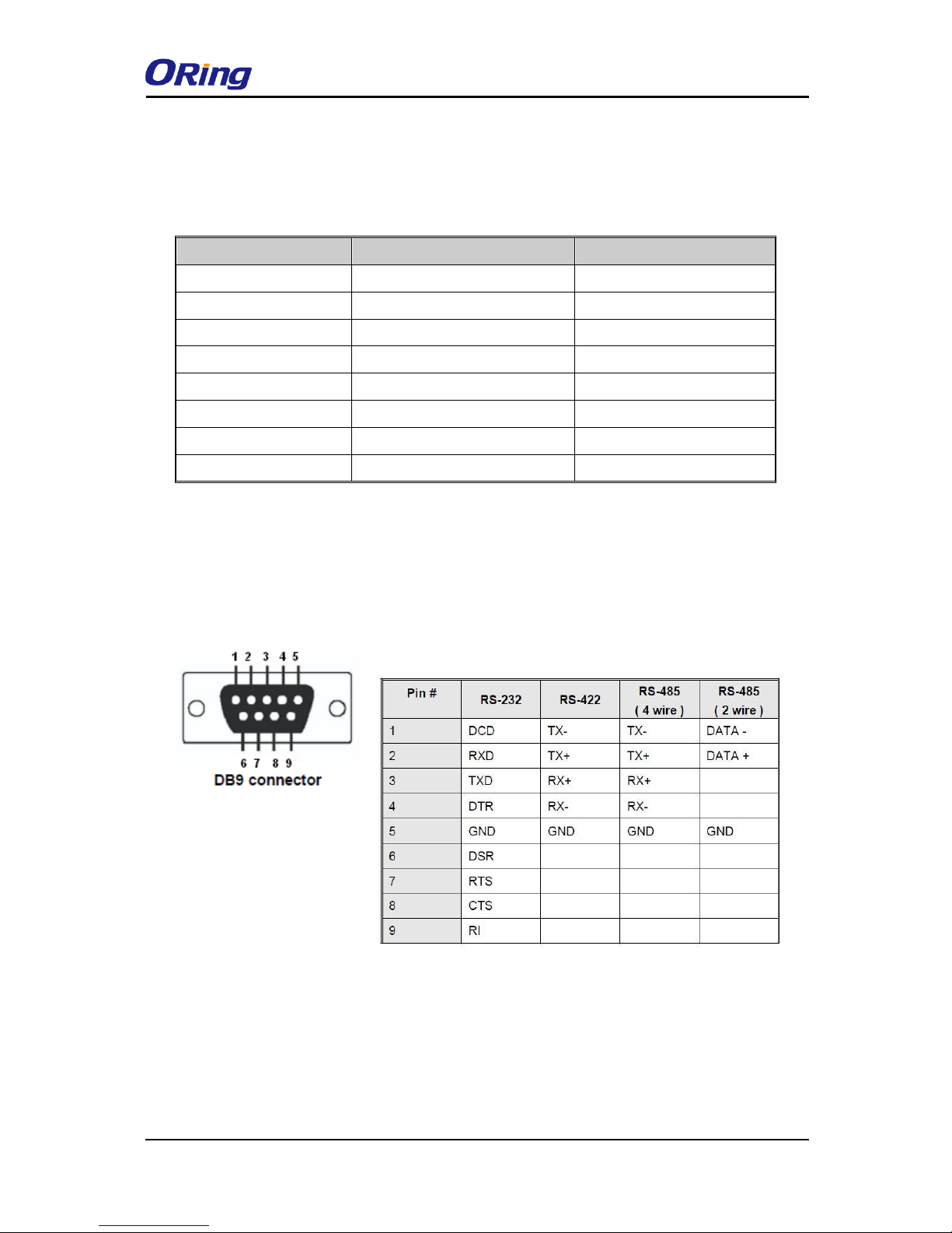
DB9 console port wiring
The serial ports can be connected using a DB9 cable. The DB9 connector supports RS232 /
RS422 / RS485 operation modes. Please refer to the following table for the pin assignments of
the DB9 connector.
Page 14
IDS-4312(+) Series User Manual
ORing Industrial Networking Corp
13
Management
4.1 DS-Tool
The Windows utility DS-Tool is a powerful Windows utility for DS series. It supports device
discovery, device configuration, group setup, group firmware update, and monitoring functions.
The tool enables you to easily install and configure devices on the network.
4.1.1 Install DS-Tool
Follow the steps below to install the tool.
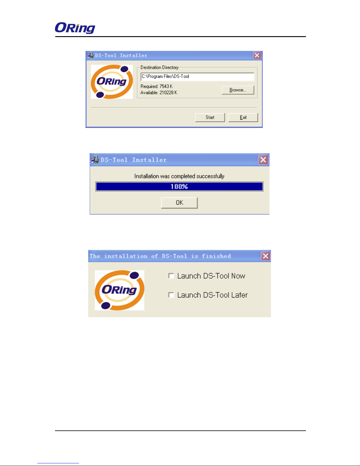
Step 1: Run the Setup program by clicking Start after selecting the folder for DS-Tool.
Page 15
IDS-4312(+) Series User Manual
ORing Industrial Networking Corp
14
Step 2: When installation completes successfully, click OK.
Step 3: You can launch the tool right immediately by checking Launch DS-Tool Now or launch
it later by checking Launch DS-Tool Later.
4.1.2 Using DS-Tool
Explore device servers
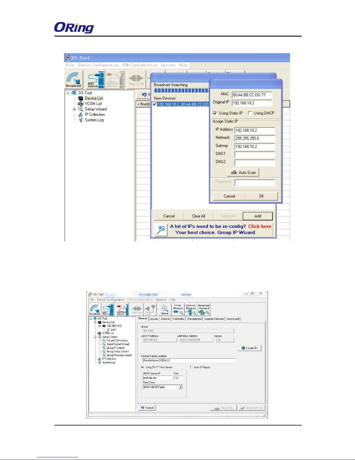
DS-Tool will broadcast to the network and search all available DS devices in the network
automatically. The default IP address of the device is “192.168.10.2”. Select the device you
wish to use and press Add button.
You can set a static IP address or use the DHCP client mode to acquire an IP address
automatically. Click OK and the device will be added.
Page 16
IDS-4312(+) Series User Manual
ORing Industrial Networking Corp
15
4.1.3 Configure Device Servers
General
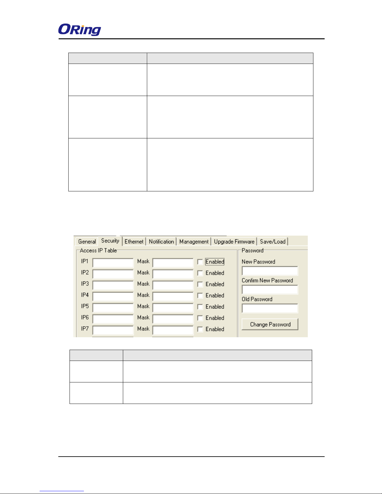
This page enables you to perform general configuration for the device, includes the device
name, SNTP server, and auto IP report.
Page 17
IDS-4312(+) Series User Manual
ORing Industrial Networking Corp
16
Label
Description
Device Name/Location
You can input the device name or related information in this
field. By clicking Locate On, you can locate the serial server’s
position.
Using SNTP Time Server
If you want to set the time via a SNTP time server, check the
box and input related information such as the SNTP server
domain name or IP address and the port number, and select a
time zone.
Auto IP Report
Check the Auto IP Report box if you want to receive IP report
regularly. By Clicking the Get Current Host, you will get your
local IP address. Input a value in the Report Interval time
based on how often you want the device server to report its
status.
Security
This page allows you to set up access IP tables for your device to allow authorized and deny
unauthorized access, thereby ensuring data security and facilitating device management.
Label
Description
Access IP Table
You can input the host IP addresses and network masks to prevent
unauthorized access.
Password
You can set the password to prevent unauthorized access from your
server. Factory default is no password.
Ethernet
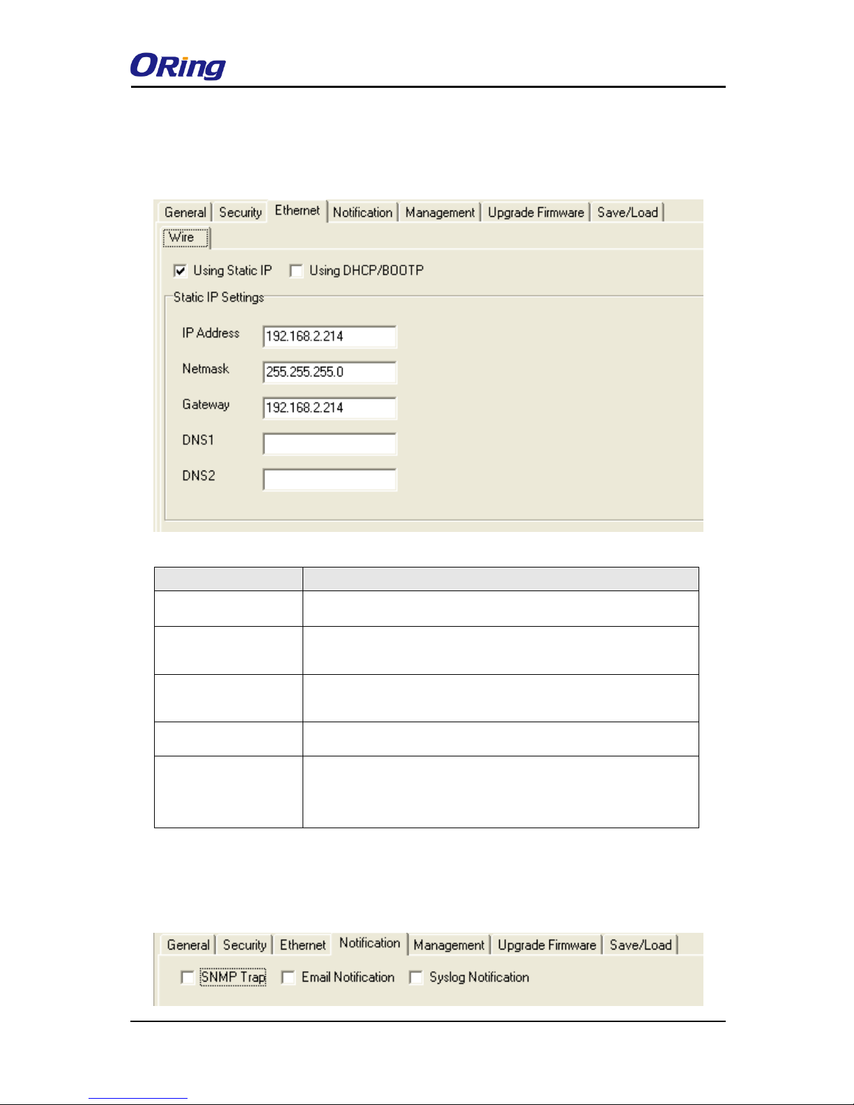
You must assign a valid IP address for DS before attached in your network environment. Your
network administrator should provide you the IP address and related settings. The IP address
Page 18
IDS-4312(+) Series User Manual
ORing Industrial Networking Corp
17
must be unique within the network (otherwise, DS will not have a valid connection to the
network). You can choose from three possible “IP configuration” modes: Static,
DHCP/BOOTP. The Factory Default IP address is “192.168.10.2”
Label
Description
Using Static IP
Manually assign an IP address to the device.
Using DHCP/BOOTP
Check this box to have the IP address automatically assigned by
a DHCP server in your network.
Netmask
All devices on the network must have the same subnet mask to
communicate on the network.
Gateway
Enter the IP address of the router in you network.
DNS1/2
Enter the IP addresses of the primary and secondary DNS
servers, The DNS server translates domain names into IP
address.
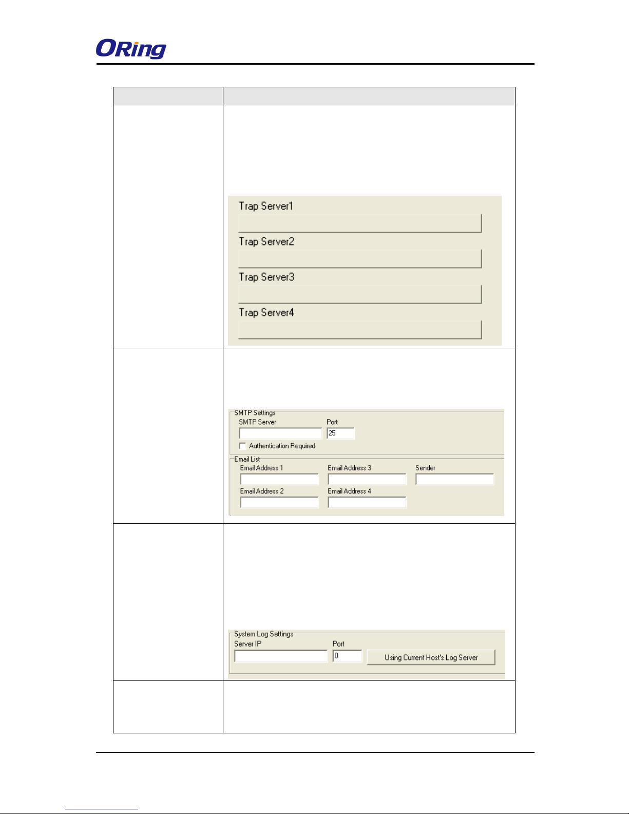
Notification
Specify the events that should be notified to the administrator. The events can be alarmed by
E-mail, SNMP trap, or Syslog.
Page 19
IDS-4312(+) Series User Manual
ORing Industrial Networking Corp
18
Label
Description
SNMP Trap
Check the box to allow the system to send SNMP traps when an
event occurs. SNMP traps are data packages sent from the SNMP
client to the server without being explicitly requested. You need to
set up trap servers that will receive these messages if the box is
checked.
Email Notification
Check the box to allow the system to send e-mails when an event
occurs. You need to specify the SMTP Server and
the email address to use for sending emails if the box is checked.
Syslog Notification
Check the box to allow the system to send a detailed log to an
external Syslog server when an event occurs. The syslog will
capture all log activity and includes every connection source and
destination IP address, IP service, and number of bytes
transferred to facilitate troubleshooting. You need to enter Server
IP address and Server Port of the syslog server.
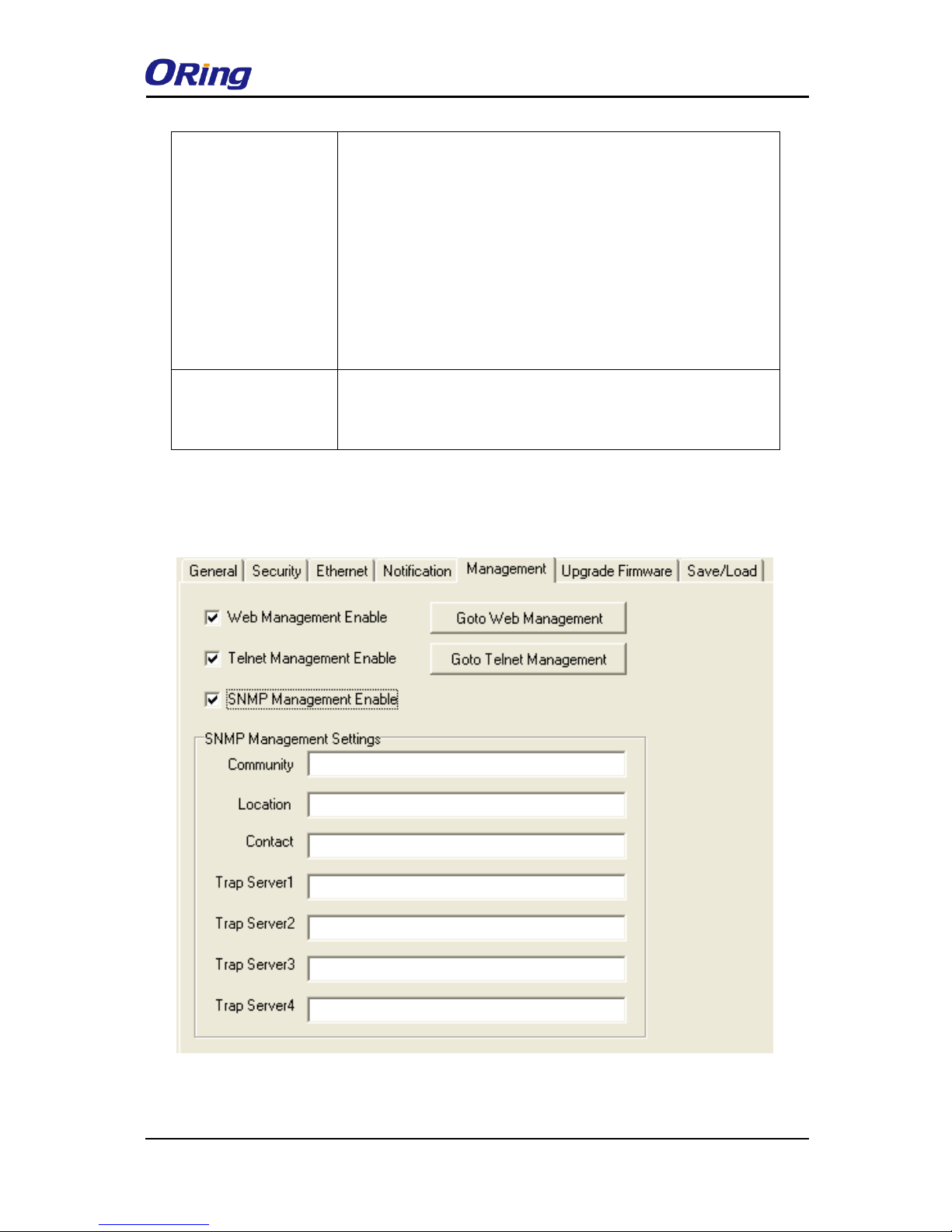
Notified items
Select the corresponding check box to send an event alert to a
remote syslog sever
・Hardware Reset (Cold Start): Rebooting the device from power
Page 20
IDS-4312(+) Series User Manual
ORing Industrial Networking Corp
19
plug will trigger the event
・Software Reset (Warm Start): Rebooting the device from Reboot
Device function from Save/Load menu will trigger the event.
・Login Failed: Using wrong password in console will trigger the
event
・IP Changed: Changing network setting will trigger the event
・Password Changed: Changing the password will trigger the
event
・Access IP Blocked: Report blocked IP addresses
System Log Settings
You can specify the server IP address and port or click Using
Current Host’s Log Server to specify current host as the log
server.
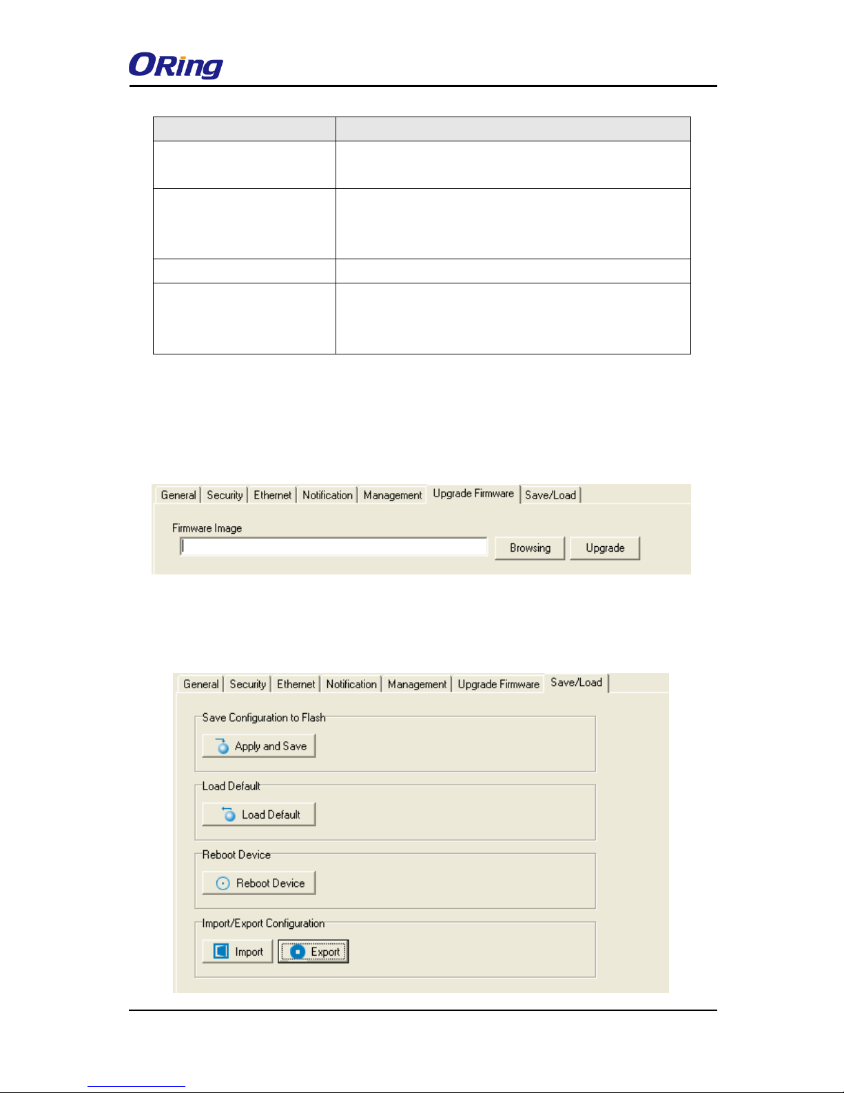
Management
This section enables you to perform management functions using different interfaces including
the Web, Telnet, and SNMP.
Page 21
IDS-4312(+) Series User Manual
ORing Industrial Networking Corp
20
Label
Description
Web Management Enable
Check the box to enable management from Web. Click
Goto Web Management button to access the Web.
Telnet Management Enable
Check the box to enable management by Telnet. Click
Goto Telnet Management button to execute Telnet
command.
SNMP Management Enable
Check the box to enable management by SNMP.
SNMP Management
Settings
If SNMP Management Enable is checked, you need to fill
in the SNMP settings in these fields by assigning the
Community, Location, Contact, and Trap Server.
Upgrade Firmware
You can find up-to-date firmware from ORing’s website. To update firmware for the device,
save the firmware file in your host PC, and then specify the file location by clicking on the
Browsing button and continue operation by pressing Update.
Save/Load
This page allows you to save the current configuration file to any local drive or any network
drive to which your management computer can connect.
Page 22
IDS-4312(+) Series User Manual
ORing Industrial Networking Corp
21
Label
Description
Apply and Save
Click this button will save all applied settings into the flash of the
appliance
Load Default
All parameters changes to factory’s default except network
settings. If you want to load all factory default, you need to press
Reset button on the device (Hardware restore).
Reboot Device
Click this button will reboot device and need to broadcast again
in order to search the device (warm start).
Import Configuration
Click this button will retrieve saved configuration file and apply it
to in current device
Export Configuration
Saving the current parameters to a file and export it to a current
host.
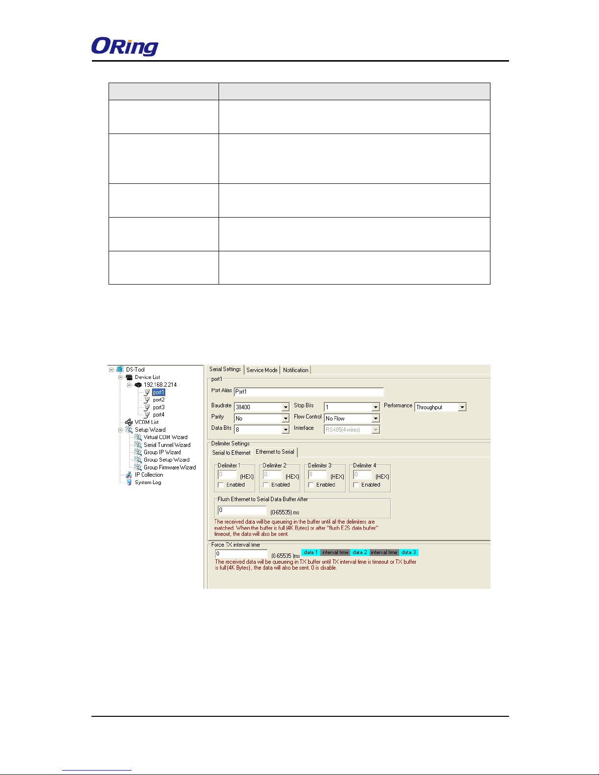
4.1.4 Configure Serial Port
You can configure the settings for each serial port by clicking on the port number in the left
panel of the window. Once you click on a port, the following screen will show up in the right
panel.
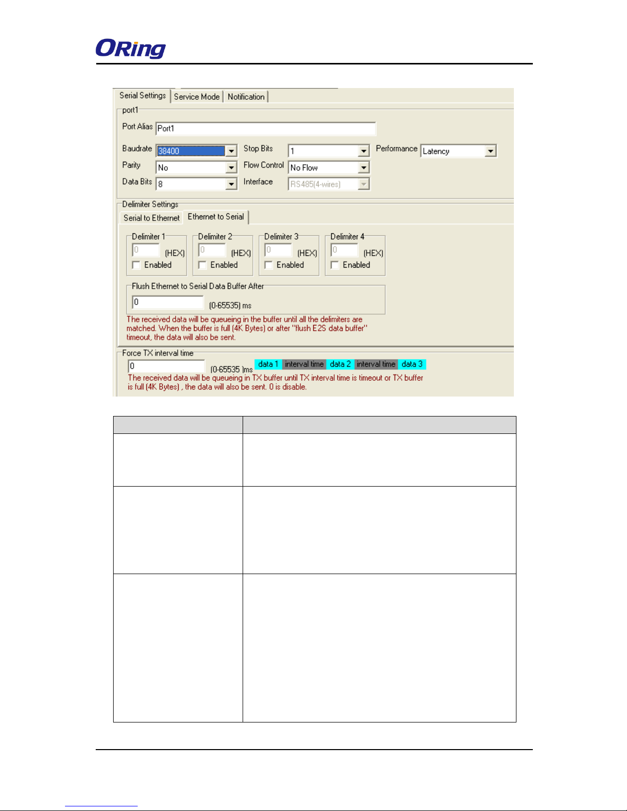
Serial Settings
The page allows you to configure serial parameters, serial communication modes, data
packing options, and event notifications.
Page 23
IDS-4312(+) Series User Manual
ORing Industrial Networking Corp
22
Label
Description
Port Alias
Port alias enables the device server to easily identify the
serial devices connected to it. Enter an identifying name to be
identified by the connected device.
Baud rate
Baud rate is the rate at which data is transferred over a serial
link. When setting the baud rate to 9600bps, the serial port
will transfer a maximum of 9600 bits per second. You can
select a baud rate from the drop-down list which ranges from
110bps to 460800bps
Parity
Parity is a simple form of error detection which guards data on
the cable between the connected devices and the serial port.
Available options include:
None: parity checking is not performed and the parity bit is
not transmitted.
Odd: the number of mark bits in the data is counted, and the
parity bit is asserted or unasserted to obtain an odd number of
Page 24

IDS-4312(+) Series User Manual
ORing Industrial Networking Corp
23
mark bits.
Even: the number of mark bits in the data is counted, and the
parity bit is asserted or unasserted to obtain an even number
of mark bits.
Mark: the parity bit is always set to the mark signal condition
(logical 1)
Space: the last transmitted data bit will always be a logical 0
Data Bits
Choose the number of data bits to transmit. You can
configure data bits to be 5, 6, 7, or 8. Data is transmitted as a
series of five, six, seven, or eight bits (five and six bit data
formats are used rarely for specialized communications
equipment).
Stop Bits
Choose the number of bits used to indicate the end of a byte.
You can configure stop bits to be 1 or 2(1.5). If Stop Bits is
1.5, the stop bit is transferred for 150% of the normal time
used to transfer one bit. Both the computer and the peripheral
device must be configured to transmit the same number of
stop bits.
Flow Control
Serial communication consists of hardware flow control and
software flow control, so called as the control is handled by
software or hardware. XOFF and OXN is software flow control
while RTS/CTS or DTR/DSR is hardware flow control.
Choose XOFF to tell the computer to stop sending data; then
the receiving side will send an XOFF character over its Tx line
to tell the transmitting side to stop transmitting. Choose XON
to tell the computer to begin sending data again; then the
receiving side will send an XON character over its Tx line to
tell the transmitting side to resume transmitting. In hardware
flow control mode, when the device is ready to receive data, it
sends a CTS (Clear To Send) signal to the device on the other
end. When a device has something it wants to send, it will
send a RTS (Ready To Send) signal and waits for a CTS
signal to come back its way. These signals are sent apart from
the data itself on separate wires.
Interface
Choose an interface for your serial device. Available
Page 25

IDS-4312(+) Series User Manual
ORing Industrial Networking Corp
24
interfaces include RS-232, RS-422, RS-485(2-wires), and
RS-485(4-wires),
Performance
Throughput: guarantees highest transmission speed.
Latency: guarantees shortest response time.
Delimiter Settings
Serial to Ethernet / Ethernet to Serial
For advanced data packing options, you can specify
delimiters for Serial to Ethernet and / or Ethernet to
Serial communications. You can define max. 4 delimiters
(00~FF, Hex) for each way. The data will be hold until the
delimiters are received or the option.
Flush Serial to Ethernet data buffer times out. 0
means disable. Factory default is 0.
Flush Data Buffer After:
The received data will be queuing in the buffer until all the
delimiters are matched. When the buffer is full (4K Bytes) or
after "flush S2E data buffer" timeout the data will also be
sent. You can set the time from 0 to 65535 seconds.
Force TX Interval Time
Force TX interval time is to specify the timeout when no data
has been transmitted. When the timeout is reached or TX
buffer is full (4K Bytes), the queued data will be sent. 0 means
disable. Factory default value is 0.
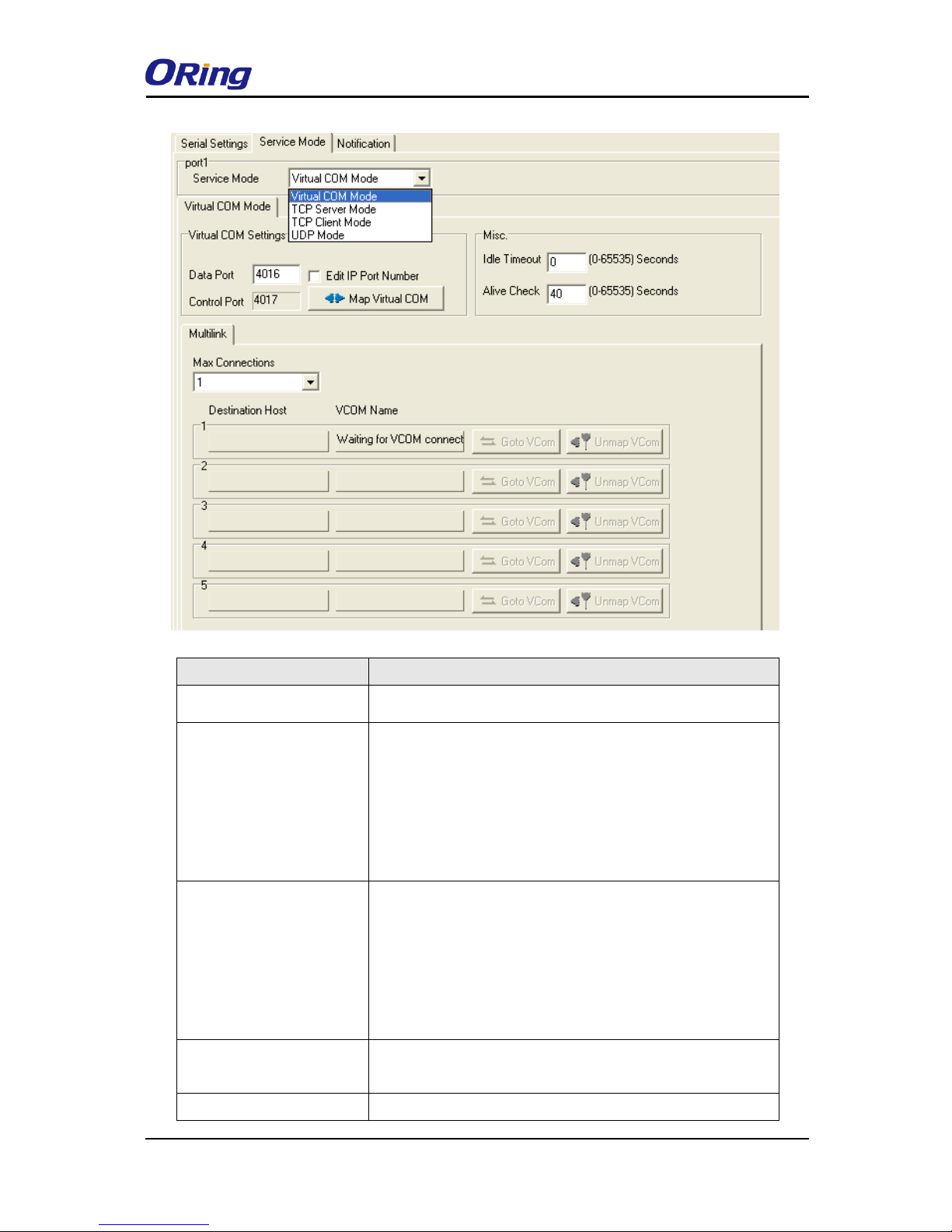
Service Mode
Virtual COM Mode
In Virtual COM Mode, the driver establishes a transparent connection between host and serial
device by mapping the port of the serial server serial port to a local COM port on the host
computer. Virtual COM Mode also supports up to 5 simultaneous connections, so that multiple
hosts can send or receive data by the same serial device at the same time.
Page 26
IDS-4312(+) Series User Manual
ORing Industrial Networking Corp
25
Label
Description
Data Port
Set the port number for data transmission.
Idle Timeout
When a serial port stops data transmission for a defined
period of time (Idle Timeout), the connection will be closed
and the port will be freed and try to connect with other hosts.
0 means the function is disabled which is also the factory
default value. If multilink is configured, only the first host
connection is effective for this setting.
Alive Check
The serial device will send a TCP alive-check package in
each defined time interval (Alive Check) to remote host to
check the the status of TCP connections. If the TCP
connection is not alive, the connection will be closed and the
port will be freed. 0 means the function is disabled which is
also the factory default value.
Max Connection
The number of max connections can be supported
simultaneously is 5; the default value is 1.
Map Virtual COM
Select a Virtual COM name to map on.
Page 27
IDS-4312(+) Series User Manual
ORing Industrial Networking Corp
26
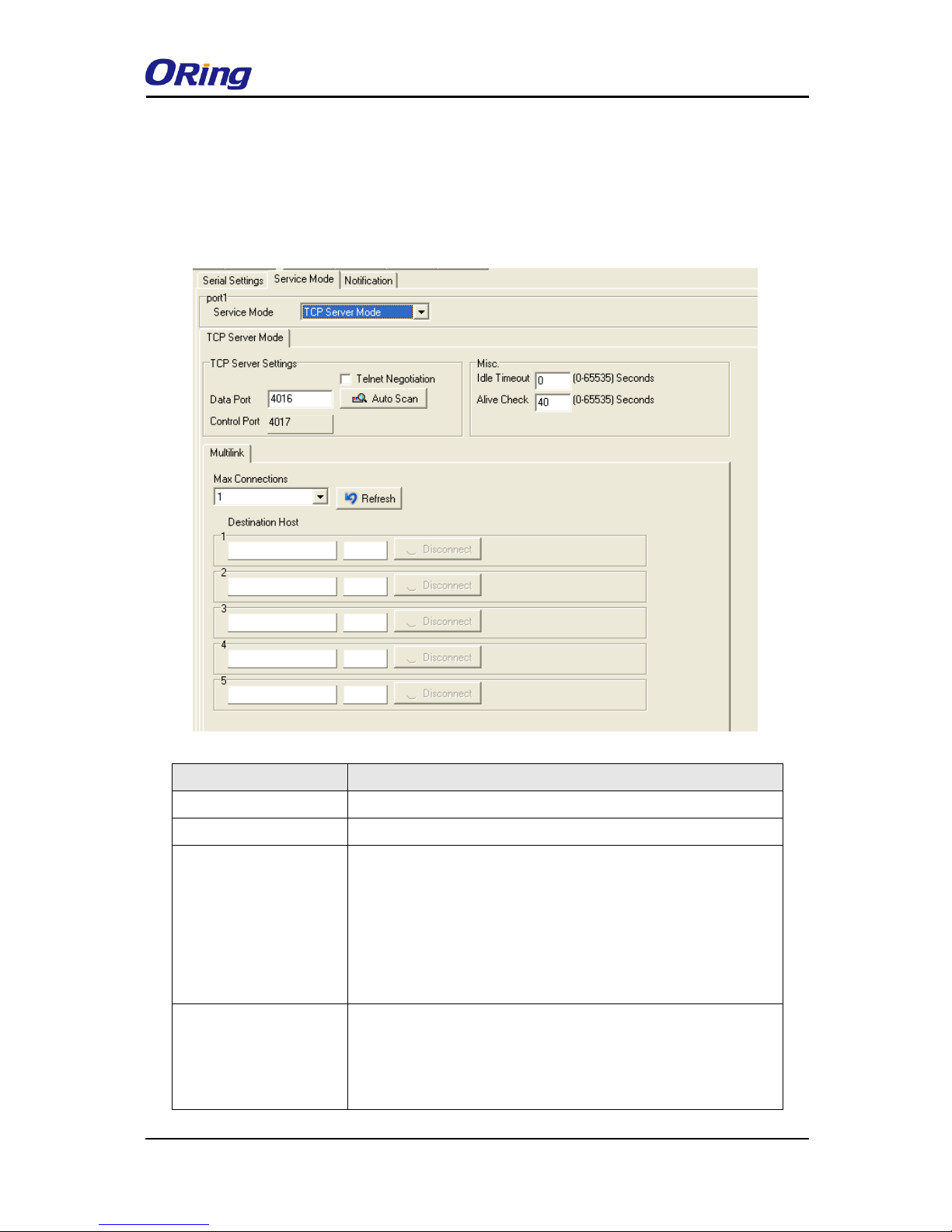
TCP Server Mode
In TCP Server mode, the serial port on the device server is assigned a unique port number.
The host computer initiates contact with the device server, establishes the connection, and
receives data from the serial device. Five simultaneous connections are supported in this
mode, enabling multiple hosts to collect data from the same serial device at the same time.
Label
Description
Data Port
Set the port number for data transmission.
Auto Scan
Scan the data port automatically.
Idle Timeout
When a serial port stops data transmission for a defined period of
time (Idle Timeout), the connection will be closed and the port will
be freed and try to connect with other hosts. 0 means the
function is disabled which is the factory default value. If multilink
is configured, only the first host connection is effective for this
setting.
Alive Check
The serial device will send a TCP alive-check package in each
defined time interval (Alive Check) to remote host to check the
TCP connection. If the TCP connection is not alive, the
connection will be closed and the port will be freed. 0 means the
Page 28
IDS-4312(+) Series User Manual
ORing Industrial Networking Corp
27
function is disabled which is the factory default value.
Max Connection
The number of maximum connections can be support
simultaneously is 5; default values is 1.
Destination Host
Input the IP address of the host.
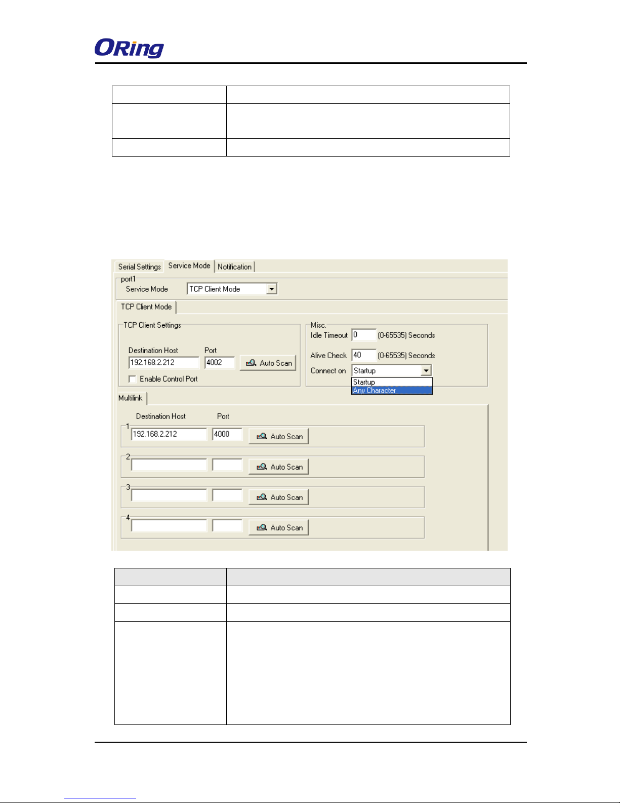
TCP Client Mode
In TCP Client mode, the device can establish a TCP connection with the server by the method
you have settled (Startup or any character). After the data has been transferred, the device can
disconnect automatically from the server by using the TCP alive check time or idle time
settings.
Label
Description
Destination Host
Input the IP address of the host.
Port
Set the port number of data port.
Idle Timeout
When a serial port stops data transmission for a defined period of
time (Idle Timeout), the connection will be closed and the port will
be freed and try to connect with other hosts. 0 means the
function is disabled which is the factory default value. If multilink
is configured, only the first host connection is effective for this
setting.
Page 29
IDS-4312(+) Series User Manual
ORing Industrial Networking Corp
28
Alive Check
The serial device will send a TCP alive-check package in each
defined time interval (Alive Check) to remote host to check the
TCP connection. If the TCP connection is not alive, the
connection will be closed and the port will be freed. 0 means the
function is disabled which is the factory default value.
Connect on Startup
The TCP Client will build a TCP connection once the connected
serial device is started.
Connect on Any
Character
The TCP Client will build a TCP connection once the connected
serial device starts to send data.
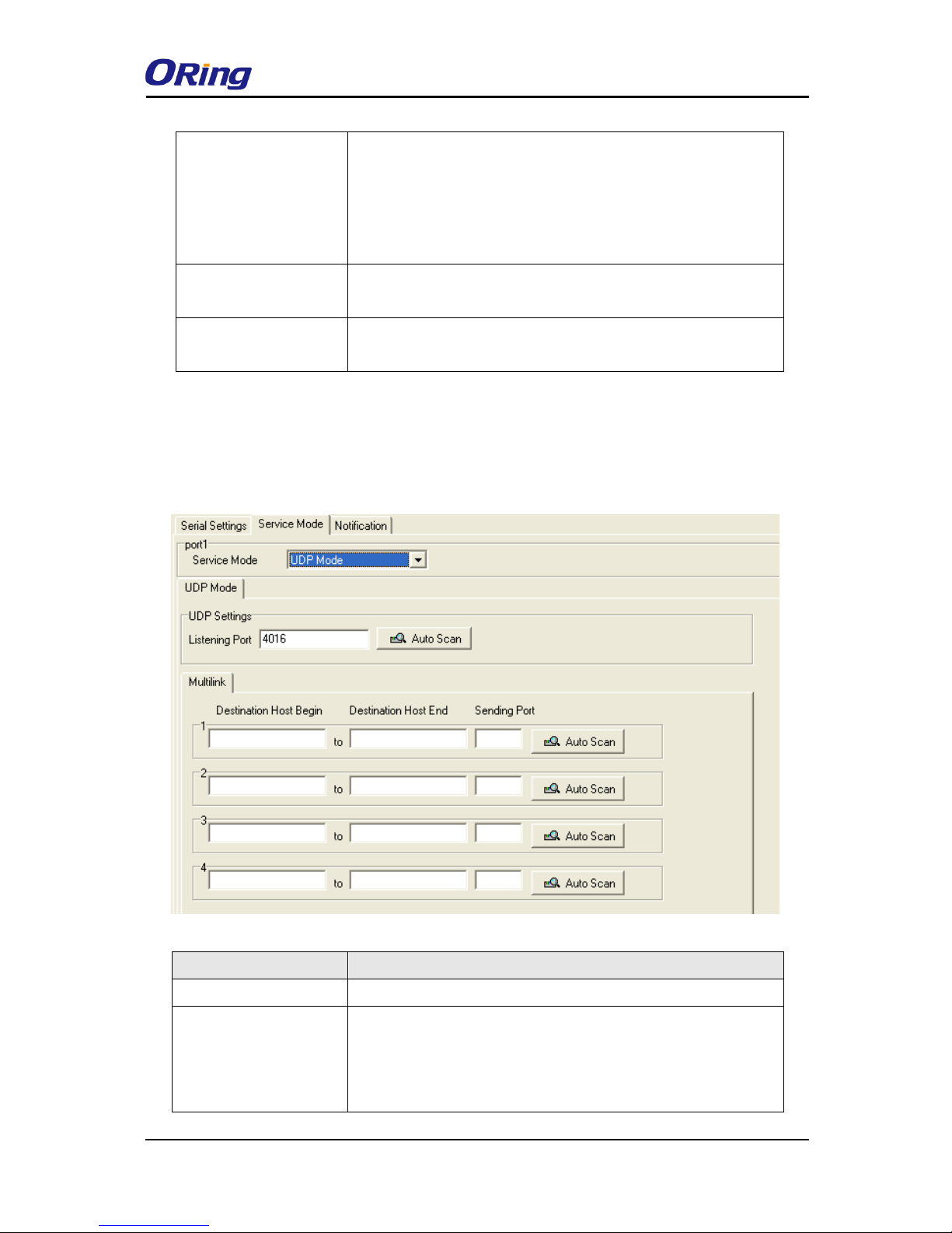
UDP Mode
Compared to TCP communication, UDP is faster and more efficient as you can unicast or
multicast data from the serial device server to host computers, and the serial device can also
receive data from one or multiple host.
Label
Description
Listening Port
IP port for listening incoming messages.
Destination Host
Begin / End
If there are more than one destination hosts, specify the IP
address range by inputting a value in destination host IP begin /
end fields. You can also auto scan the sending port number of
the device.
Page 30
IDS-4312(+) Series User Manual
ORing Industrial Networking Corp
29
Sending Port
IP port for sending outgoing messages.
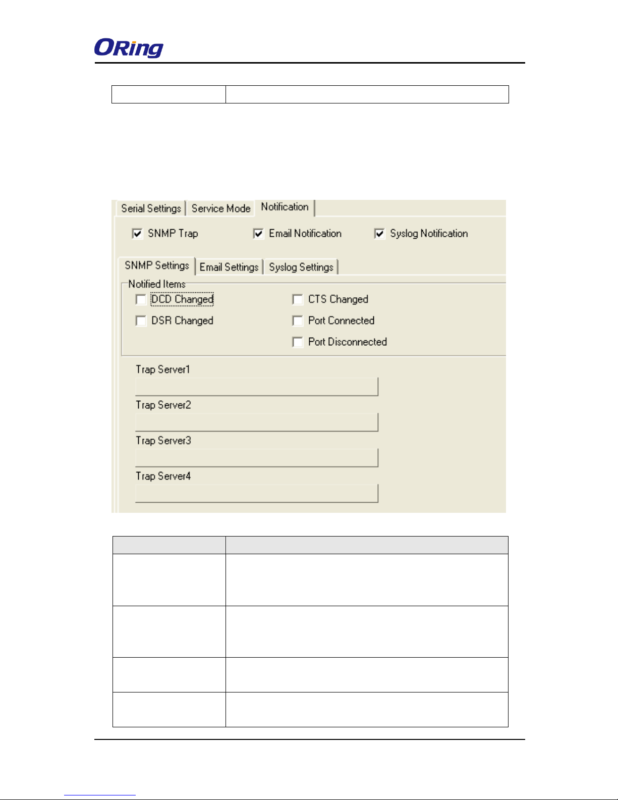
Notification
Port status can be notified to administrator by means of Email, SNMP trap, or System
Log. You can specify the events that should be noticed and the notification methods in
this page.
Label
Description
DCD changed
When DCD (Data Carrier Detect) signal changes, it indicates that
the modem connection status has changed. A notification will be
sent if the box is checked.
DSR changed
When DSR (Data Set Ready) signal changes, it indicates that the
data communication equipment is powered off. A notification will
be sent if the box is checked.
RI changed
When RI (Ring Indicator) signal changes, it indicates that the
incoming of a call. A notification will be sent if the box is checked.
CTS changed
When CTS (Clear To Send) signal changes, it indicates that the
transmission between computer and DCE can proceed. A
Page 31
IDS-4312(+) Series User Manual
ORing Industrial Networking Corp
30
notification will be sent if the box is checked.
Port connected
In TCP Server Mode, when the device accepts an incoming TCP
connection, this event will be triggered. In TCP Client Mode,
when the device has connected to the remote host, this event will
be triggered. In Virtual COM Mode, Virtual COM is ready to use.
A notification will be sent if the box is checked.
Port disconnected
In TCP Server/Client Mode, when the device loses the TCP link,
this event will be triggered. In Virtual COM Mode, when Virtual
COM is not available, this event will be triggered. A notification
will be sent if the box is checked.
4.2 Web Management
The device can be managed via a built-in web server which supports Internet Explorer
(Internet Explorer 5.0 or above versions) and other Web browsers such as Chrome. Therefore,
you can manage and configure the device easily and remotely. You can also upgrade firmware
via a Web browser. The Web management function not only reduces network bandwidth
consumption, but also enhances access speed and provides a user-friendly viewing screen.
Note: By default, IE5.0 or later version do not allow Java applets to open sockets. You need to modify the
browser setting separately in order to enable Java applets for network ports.
Management via Web Browser
Follow the steps below to manage your device via a Web browser
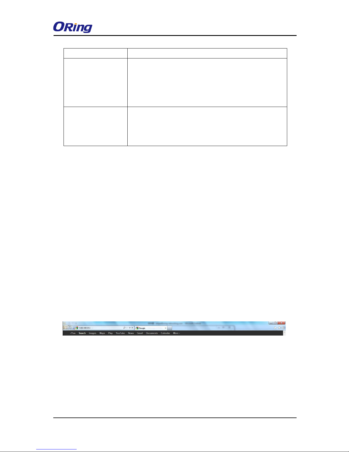
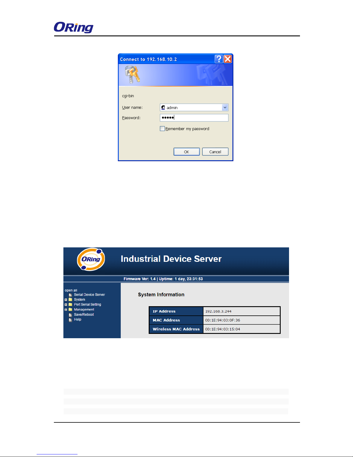
System Login
1. Launch an Internet Explorer.
2. Type http:// and the IP address of the device. Press Enter.
3. A login screen appears.
4. Type in the username and password. The default username and password is
admin.
5. Press Enter or click OK, the management page appears.
Page 32
IDS-4312(+) Series User Manual
ORing Industrial Networking Corp
31
Note: you can use the following default values:
IP Address: 192.168.10.1
Subnet Mask: 255.255.255.0
Default Gateway: 192.168.10.254
User Name: admin
Password: admin
After logging in, you will see the information of the device as below.
On the left hand side of the management interface shows links to various settings. Clicking on
the links will bring you to individual configuration pages.
4.2.1 System
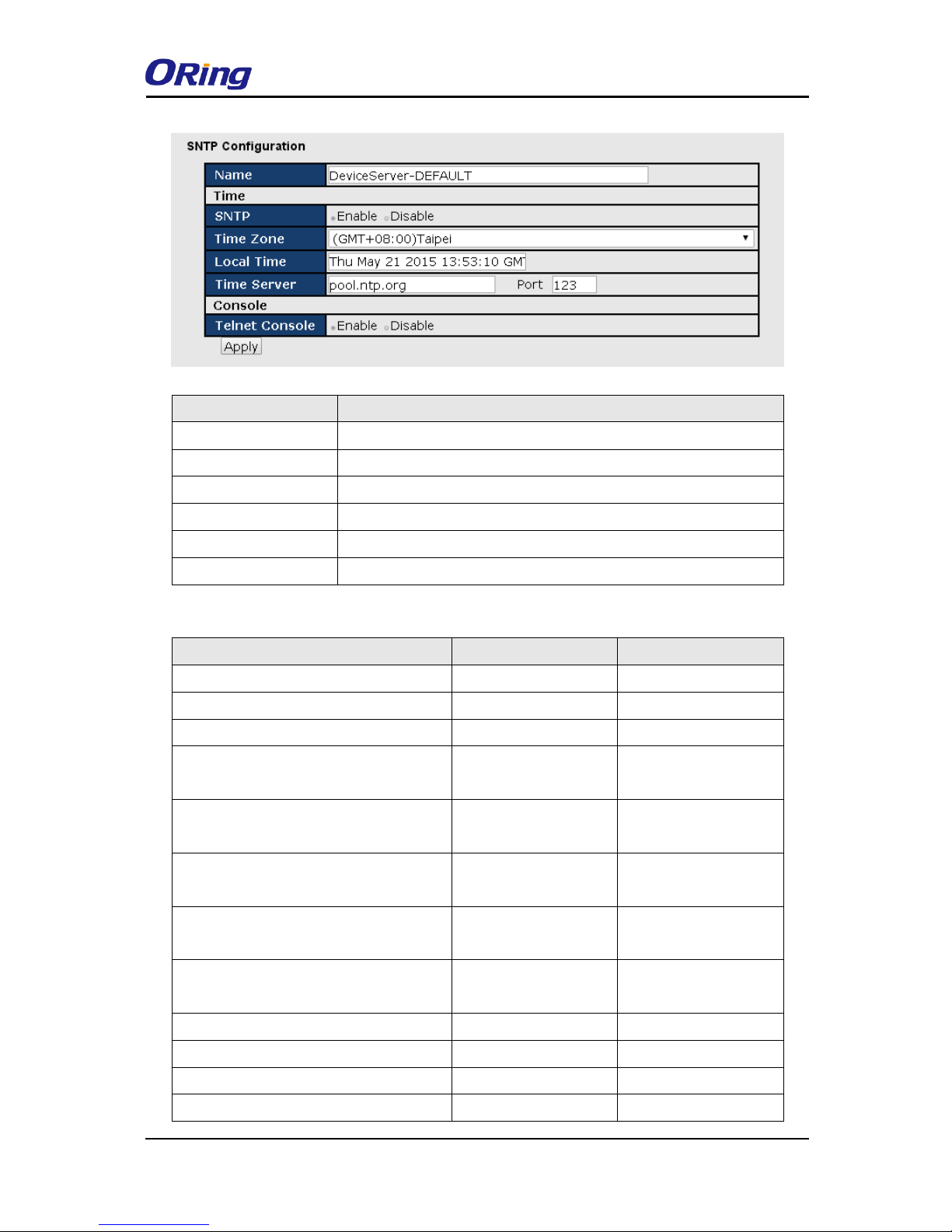
Time (SNTP)
SNTP (Simple Network Time Protocol) is a protocol able to synchronize the time on your
system to the clock on the Internet. It will synchronize your computer system time with a server
that has already been synchronized by a source such as a radio, satellite receiver or modem.
Page 33
IDS-4312(+) Series User Manual
ORing Industrial Networking Corp
32
Label
Description
Name
Enter the model name of the device.
SNTP
Enable or disable SNTP function.
Time Zone
Choose the time zone according to the location of the device.
Local Time
Set up the local time.
Time Server
Enter the address of the time server.
Telnet Console
Click to enable or disable Telnet console function.
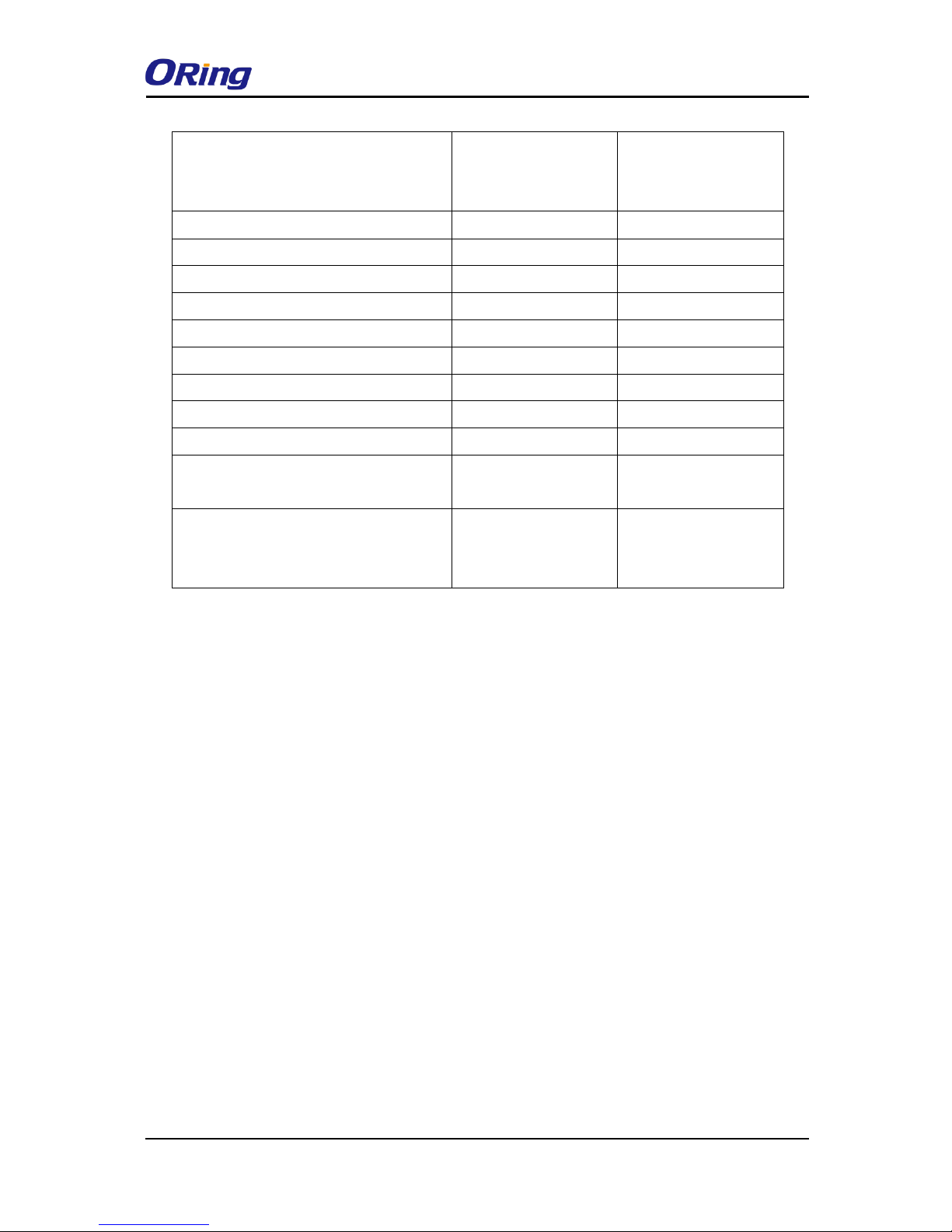
The following table lists different location time zones for your reference.
Local Time Zone
Conversion from UTC
Time at 12:00 UTC
November Time Zone
- 1 hour
11 am
Oscar Time Zone
-2 hours
10 am
ADT - Atlantic Daylight
-3 hours
9 am
AST - Atlantic Standard EDT - Eastern
Daylight
-4 hours
8 am
EST - Eastern Standard CDT - Central
Daylight
-5 hours
7 am
CST - Central Standard MDT - Mountain
Daylight
-6 hours
6 am
MST - Mountain Standard PDT - Pacific
Daylight
-7 hours
5 am
PST - Pacific Standard ADT - Alaskan
Daylight
-8 hours
4 am
ALA - Alaskan Standard
-9 hours
3 am
HAW - Hawaiian Standard
-10 hours
2 am
Nome, Alaska
-11 hours
1 am
CET - Central European FWT - French
+1 hour
1 pm
Page 34
IDS-4312(+) Series User Manual
ORing Industrial Networking Corp
33
Winter MET - Middle European MEWT Middle European Winter SWT - Swedish
Winter
EET - Eastern European, USSR Zone 1
+2 hours
2 pm
BT - Baghdad, USSR Zone 2
+3 hours
3 pm
ZP4 - USSR Zone 3
+4 hours
4 pm
ZP5 - USSR Zone 4
+5 hours
5 pm
ZP6 - USSR Zone 5
+6 hours
6 pm
WAST - West Australian Standard
+7 hours
7 pm
CCT - China Coast, USSR Zone 7
+8 hours
8 pm
JST - Japan Standard, USSR Zone 8
+9 hours
9 pm
EAST - East Australian
+10 hours
10 pm
Standard GST Guam Standard, USSR
Zone 9
IDLE - International Date Line NZST New Zealand Standard NZT - New
Zealand
+12 hours
Midnight
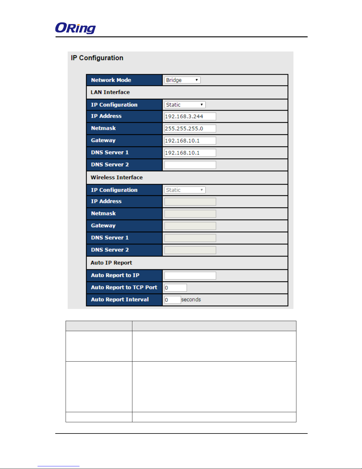
IP Configuration
This page allows you to configure IP settings for the device. You can assign an IP address
manually or leave it to DHCP/BOOTP servers which will reply with an automatically
generated IP address and subnet mask for the device when they receive the request. The IP
address must be unique and within the network, otherwise the device will not have a valid
connection to the network. Select Static IP if you are using a fixed IP address. Click Apply
after you complete configuration.
Page 35
IDS-4312(+) Series User Manual
ORing Industrial Networking Corp
34
Label
Description
Network Mode
Two network modes are available. By enabling the bridge
mode, you can apply a second LAN port as a switching port to
connect with an Ethernet-based device.
IP Configuration
Choose to use a static or DHCP-assigned IP. If you choose
DHCP, the following fields will gray out.
Static: Input an IP address for the device.
DHCP/BOOTP: allows the IP address of the device to be
automatically assigned by a configuration server.
IP Address
Enter the IP address that identifies the server on the TCP/IP
Page 36
IDS-4312(+) Series User Manual
ORing Industrial Networking Corp
35
network.
Netmask
Enter a subnet mask for the device.
Gateway
Enter the IP address of the router that provides network access
outside the server’s LAN.
DNS Server 1/2
Enter the IP address of the primary and secondary domain
name server.
Auto Report to IP
Specify an IP address for reports generated by the Auto report function
to be automatically sent to.
Auto Report to TCP Port
Specify a TCP Port for reports generated by the Auto report function to
be automatically sent to.
Auto Report Interval
Specify a time interval for which reports will be delivered.
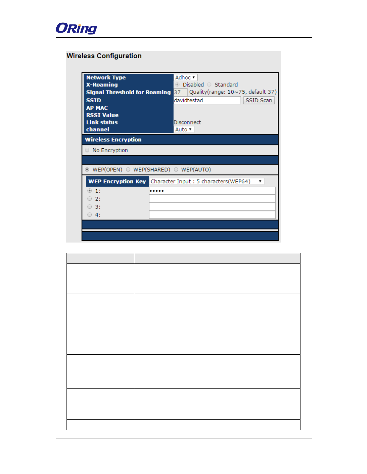
Wireless Configuration
Wireless network type includes two modes: INFRA and ADHOC. The INFRA type connects the
network by wireless access points, and the ADHOC is formed by the association of wireless
and mobile devices capable of communicating among themselves even when there is no
networking INFRA structure available.
Page 37
IDS-4312(+) Series User Manual
ORing Industrial Networking Corp
36
Label
Description
Network Type
You can choose INFRA or ADHOC type.
X-roaming
Click the button to enable or disable X-roaming function.
Signal Threshold for
Roaming
Specify the signal Threshold for roaming.
SSID
Service Set Identifier Default is the default setting. The SSID is
a unique name that identifies a network. All devices on a
network must share the same SSID name in order to
communicate on the network.
AP MAC
Displays the AP's MAC address.
RSSI Value
Indicates wireless signal strength.
Link Status
Indicates the status of wireless connection.
Channel
All devices on the network must be set to the same channel to
communicate on the network. You can select the Auto.
Encryption
You can set the device to use no encryption, but this mode is not
Page 38
IDS-4312(+) Series User Manual
ORing Industrial Networking Corp
37
secure and is not recommended. You can also use WEP
encryption to protect data. With WEP (Shared), both
communication devices use the same key as encryption. If WEP
(Auto) is selected, the system will detect the WEP situation of
the access point automatically.
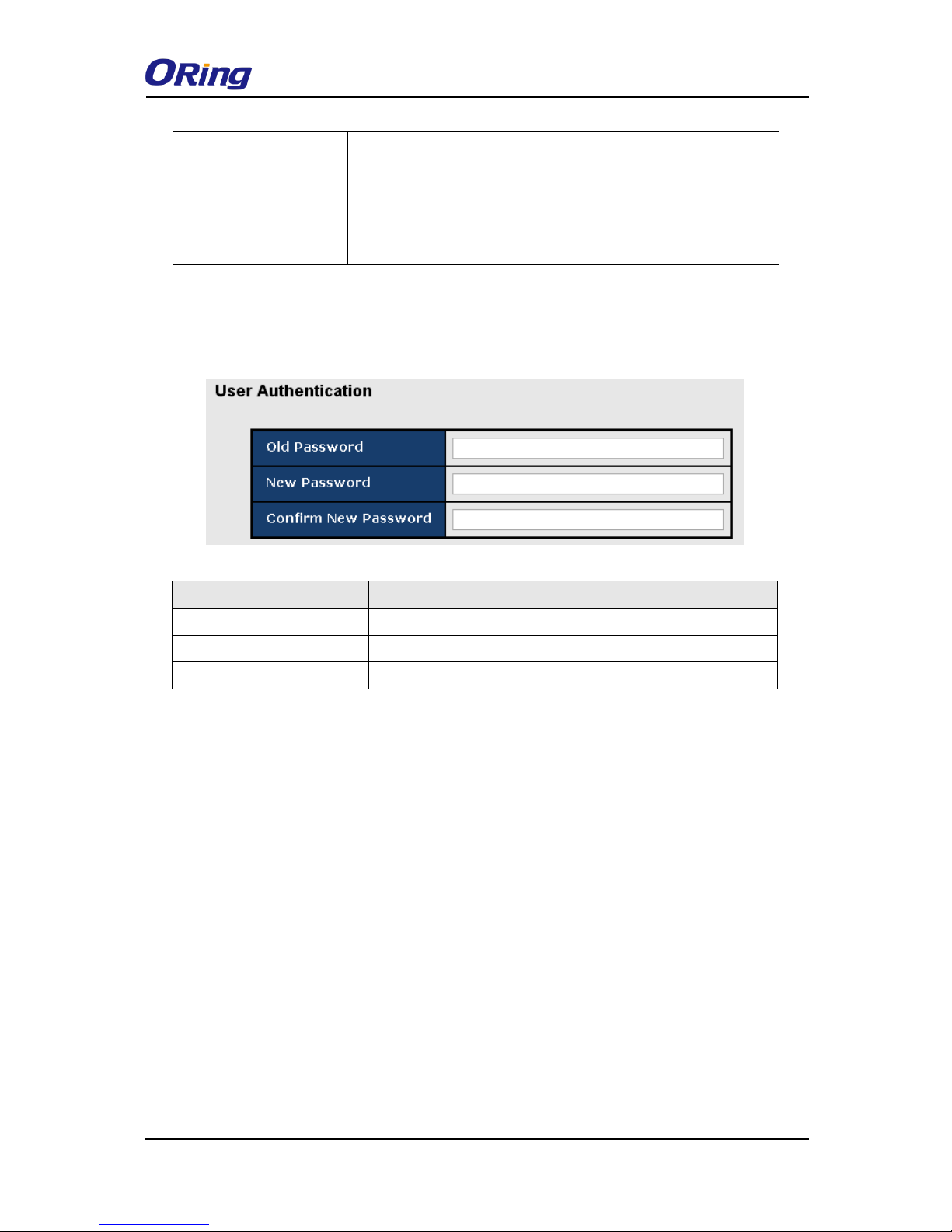
User Authentication
This page allows you to set up login account and password. You can also change your
password in this page.
Label
Description
Old Password
Enter the existing password that is used to log in.
New Password
Enter a new password that will be used to log in.
Confirm New Password
Retype the new password to confirm.
Port Serial Setting
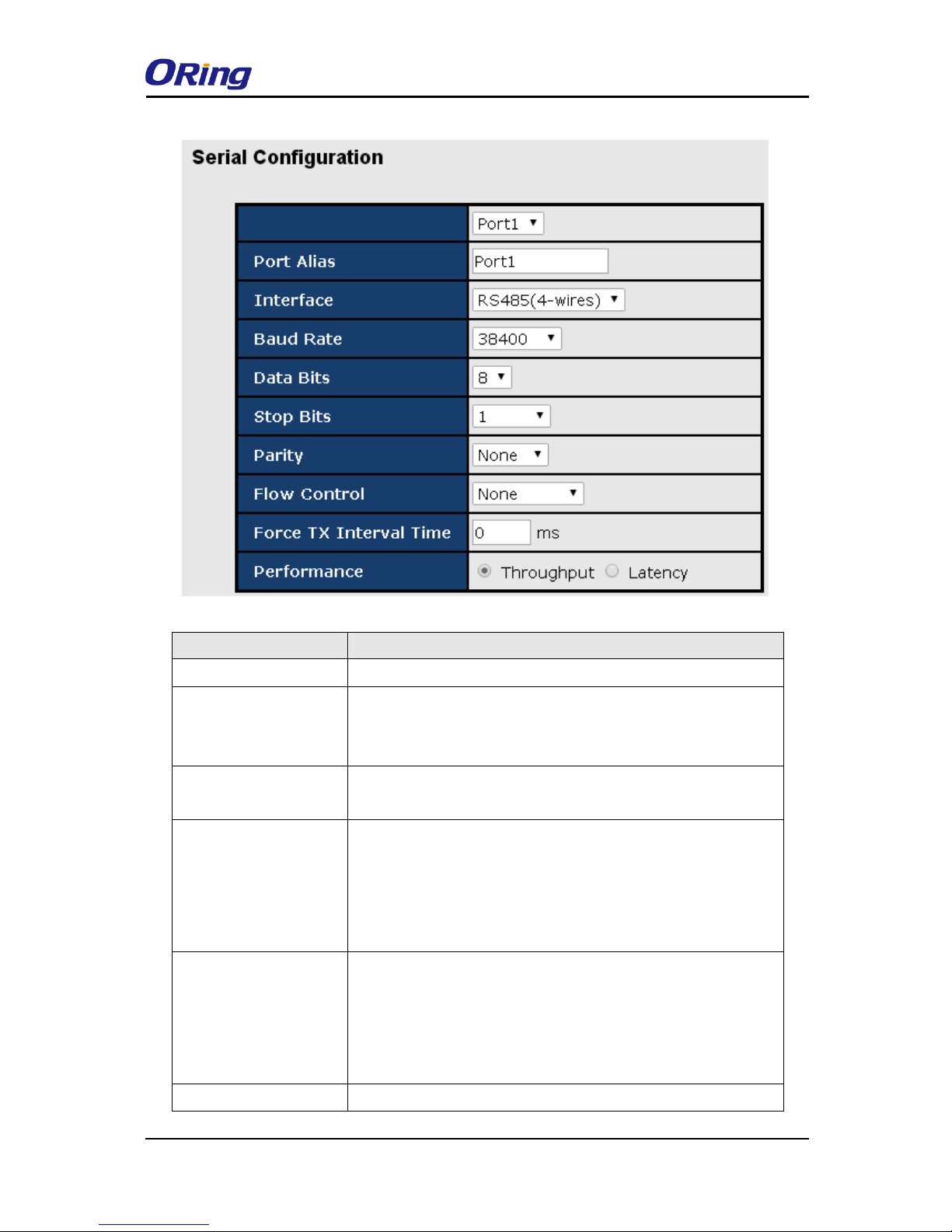
Serial Configuration
This page allows you to configure serial port parameters.
Page 39
IDS-4312(+) Series User Manual
ORing Industrial Networking Corp
38
Label
Description
Port Alias
Enter the COM port number that modem is connected to
Interface
Choose an interface for your serial device. Available interfaces
include RS-232, RS-422, RS-485(2-wires), and
RS-485(4-wires),
Baud Rate
Choose a baud rate in the range between 110 bps and 460800
bps.
Data Bits
Choose the number of data bits to transmit. You can
configure data bits to be 5, 6, 7, or 8. Data is transmitted as a
series of five, six, seven, or eight bits (five and six bit data
formats are used rarely for specialized communications
equipment).
Stop Bits
Choose the number of bits used to indicate the end of a byte. You
can configure stop bits to be 1 or 2(1.5). If Stop Bits is 1.5, the
stop bit is transferred for 150% of the normal time used to
transfer one bit. Both the computer and the peripheral device
must be configured to transmit the same number of stop bits.
Parity
Chose the method of detecting errors in transmission. Parity
Page 40

IDS-4312(+) Series User Manual
ORing Industrial Networking Corp
39
control bit modes include None, Odd, Even, Mark, and Space.
None: parity checking is not performed and the parity bit is not
transmitted.
Odd: the number of mark bits in the data is counted, and the
parity bit is asserted or unasserted to obtain an odd number of
mark bits.
Even: the number of mark bits in the data is counted, and the
parity bit is asserted or unasserted to obtain an even number of
mark bits.
Mark: the parity bit is always set to the mark signal condition
(logical 1)
Space: the last transmitted data bit will always be a logical 0.
Flow Control
Serial communication consists of hardware flow control and
software flow control, so called as the control is handled by
software or hardware. XOFF and OXN is software flow control
while RTS/CTS or DTR/DSR is hardware flow control.
Choose XOFF to tell the computer to stop sending data; then the
receiving side will send an XOFF character over its Tx line to tell
the transmitting side to stop transmitting. Choose XON to tell the
computer to begin sending data again; then the receiving side
will send an XON character over its Tx line to tell the transmitting
side to resume transmitting. In hardware flow control mode,
when the device is ready to receive data, it sends a CTS (Clear
To Send) signal to the device on the other end. When a device
has something it wants to send, it will send a RTS (Ready To
Send) signal and waits for a CTS signal to come back its way.
These signals are sent apart from the data itself on separate
wires.
FaceTX Interval Time
Force TX interval time is to specify the timeout when no data has
been transmitted. When the timeout is reached or TX buffer is full
(4K Bytes), the queued data will be sent. 0 means disable.
Factory default value is 0.
Performance
Throughput: This mode optimized for highest transmission
speed.
Latency: This mode optimized for shortest response time.
Page 41
IDS-4312(+) Series User Manual
ORing Industrial Networking Corp
40
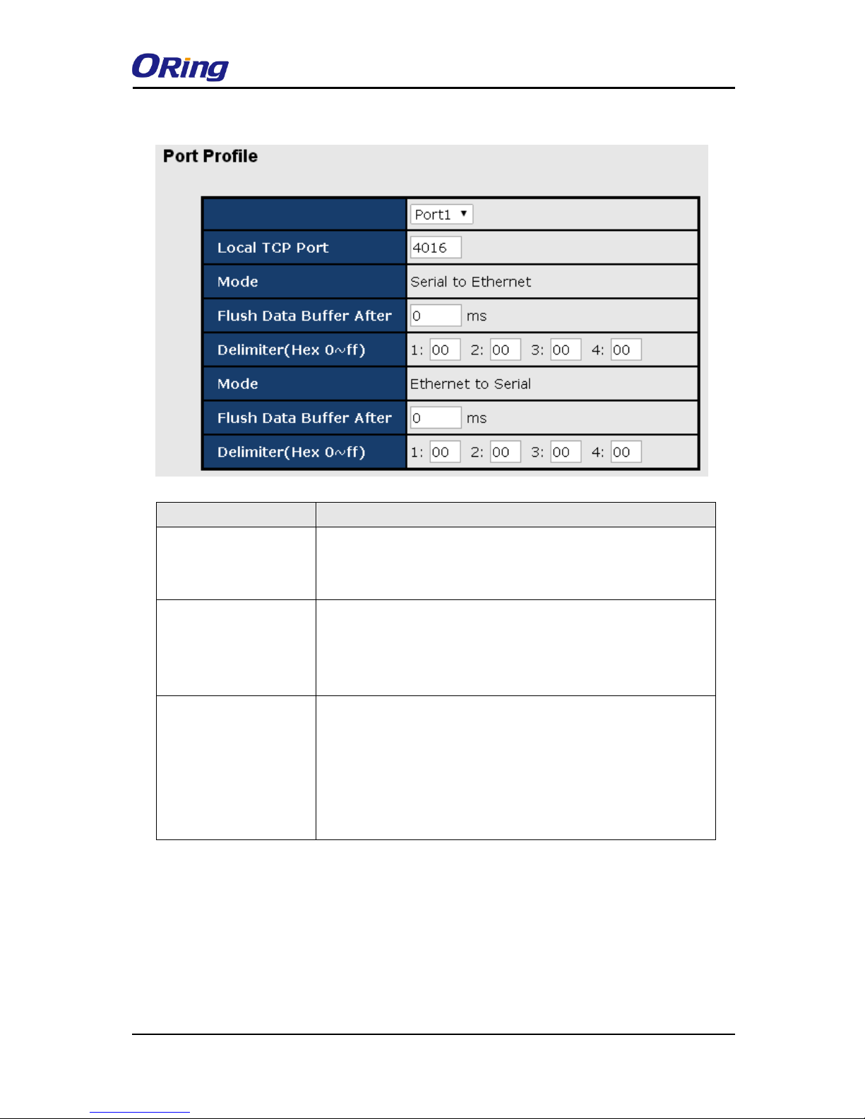
Port Profile
Label
Description
Local TCP Port
The TCP port the device uses to listen to connections, and that
other devices must use to contact the device. To avoid conflicts
with well known TCP ports, the default is set to 4000.
Flush Data Buffer After
The received data will be queuing in the buffer until all the
delimiters are matched. When the buffer is full (4K Bytes) or
after "flush S2E data buffer" timeout the data will also be
sent. You can set the time from 0 to 65535 seconds.
Delimiter
For advanced data packing options, you can specify
delimiters for Serial to Ethernet and / or Ethernet to Serial
communications. You can define max. 4 delimiters (00~FF,
Hex) for each way. The data will be hold until the delimiters
are received or the option Flush Serial to Ethernet data
buffer times out. 0 means disable. Factory default is 0.
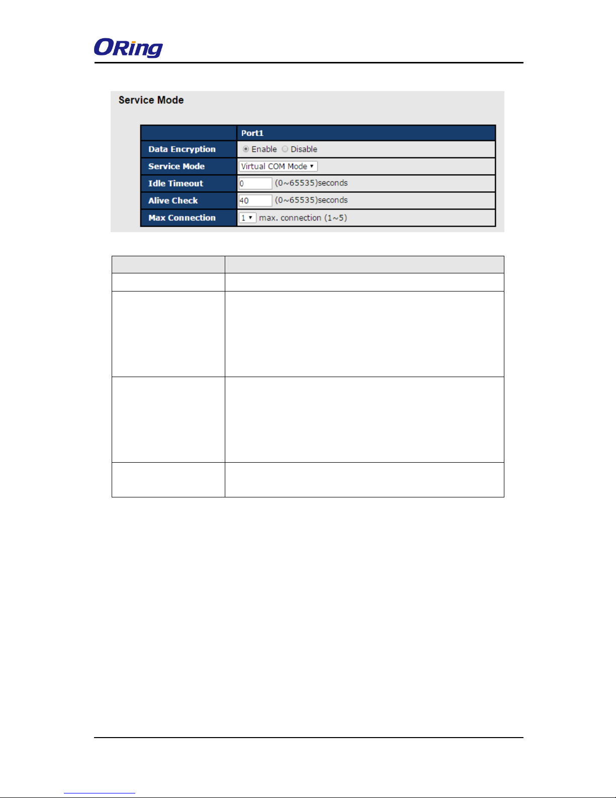
Service Mode - Virtual COM Mode
In Virtual COM Mode, the driver establishes a transparent connection between the host and
the serial device by mapping the port of the serial server to a local COM port on the host
computer. Virtual COM Mode also supports up to 5 simultaneous connections, so that multiple
hosts can send or receive data by the same serial device at the same time.
Page 42
IDS-4312(+) Series User Manual
ORing Industrial Networking Corp
41
Label
Description
Data Encryption
Click on the radio button to enable or disable data encryption
Idle Timeout
When serial port stops data transmission for a defined period of
time, the connection will be closed and the port will be freed and
try to connect with other hosts. 0 indicate disable this function.
Factory default value is 0. If Multilink is configured, only the first
host connection is effective for this setting.
Alive Check
The serial device will send TCP alive-check packages in each
defined time interval to remote host to check the TCP
connection. If the TCP connection is not alive, the connection
will be closed and the port will be freed. 0 indicate disable this
function. Factory default is 0.
Max Connection
The number of Max connection can support simultaneous
connections are 5, default values is 1.
*Not allowed to mapping Virtual COM from web
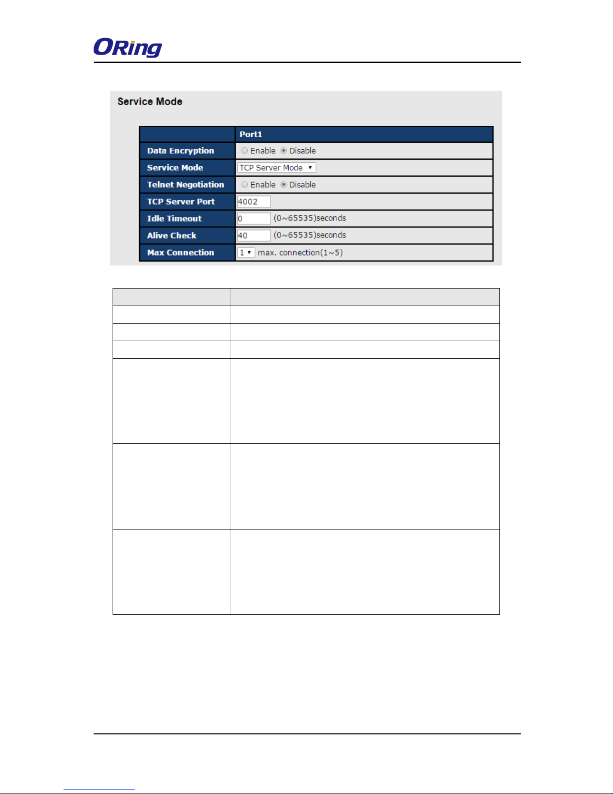
Service Mode – TCP Server Mode
In TCP Server Mode, DS is configured with a unique port combination on a TCP/IP network.
In this case, DS waits passively to be contacted by the device. After the device establishes a
connection with the serial device, it can then proceed with data transmission. TCP Server
mode also supports up to 5 simultaneous connections, so that multiple device can receive data
from the same serial device at the same time.
Page 43
IDS-4312(+) Series User Manual
ORing Industrial Networking Corp
42
Label
Description
Data Encryption
Click on the radio button to enable or disable data encryption.
Telnet Negotiation
Enables or disables Telnet Negotiation protocol encryption.
TCP Server Port
Enter the TCP server port number.
Idle Timeout
When serial port stops data transmission for a defined period
of time, the connection will be closed and the port will be freed
and try to connect with other hosts. 0 indicate disable this
function. Factory default value is 0. If Multilink is configured,
only the first host connection is effective for this setting.
Alive Check
The serial device will send TCP alive-check package in each
defined time interval (Alive Check) to remote host to check the
TCP connection. If the TCP connection is not alive, the
connection will be closed and the port will be freed. 0 indicate
disable this function. Factory default is 0.
Max Connection
The serial device will send TCP alive-check packages in each
defined time interval to remote host to check the TCP
connection. If the TCP connection is not alive, the connection
will be closed and the port will be freed. 0 indicate disable this
function. Factory default is 0.
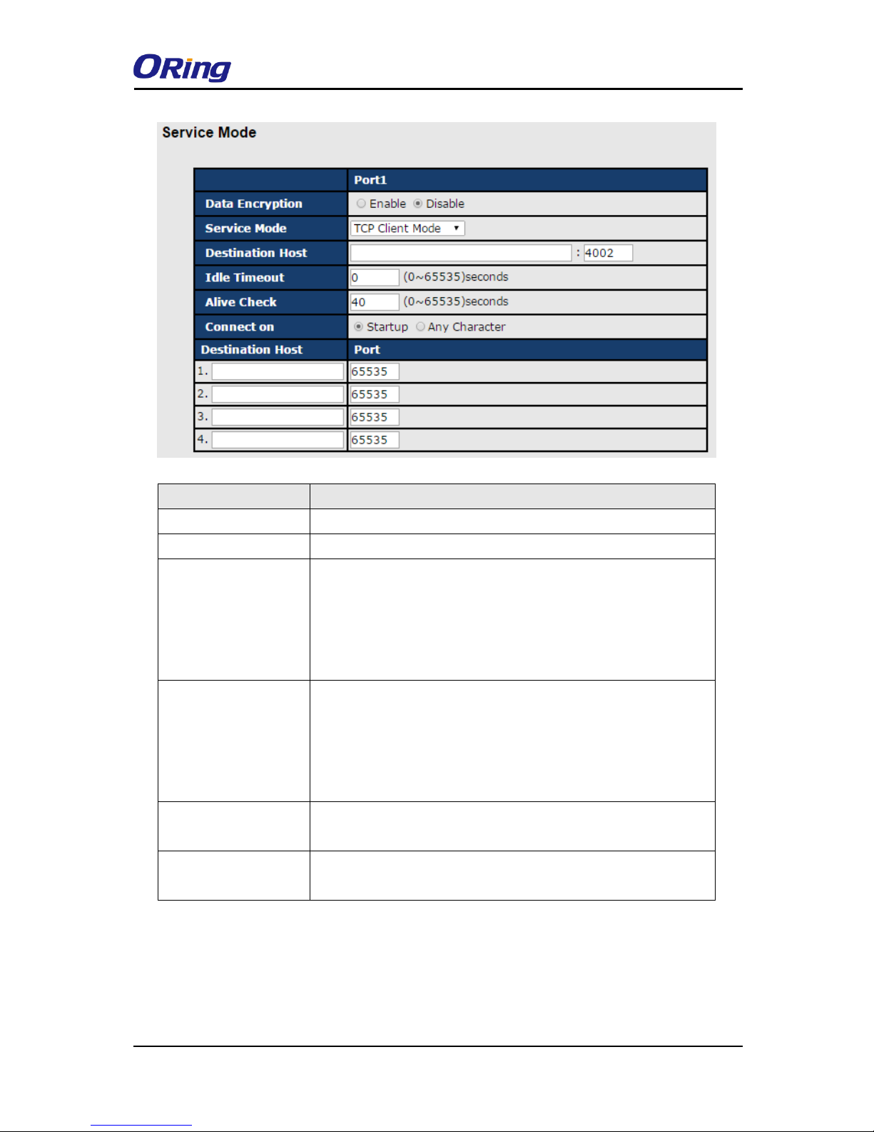
Service Mode – TCP Client Mode
In TCP Client Mode, the device can establish a TCP connection with the server by the method
you set (Startup or any character). After the data has been transferred, the device can
disconnect automatically from the server by using the TCP alive check time or idle timeout
settings.
Page 44
IDS-4312(+) Series User Manual
ORing Industrial Networking Corp
43
Label
Description
Data Encryption
Click on the radio button to enable or disable data encryption.
Destination Host
Set the IP address of host and the port number of data port. .
Idle Timeout
When serial port stops data transmission for a defined period of
time, the connection will be closed and the port will be freed and
try to connect with other hosts. 0 indicate disable this function.
Factory default value is 0. If Multilink is configured, only the first
host connection is effective for this setting.
Alive Check
The serial device will send TCP alive-check packages in each
defined time interval to remote host to check the TCP connection.
If the TCP connection is not alive, the connection will be closed
and the port will be freed. 0 indicate disable this function. Factory
default is 0.
Connect on Startup
The TCP Client will build TCP connection once the connected
serial device is started.
Connect on Any
Character
The TCP Client will build TCP connection once the connected
serial device starts to send data.
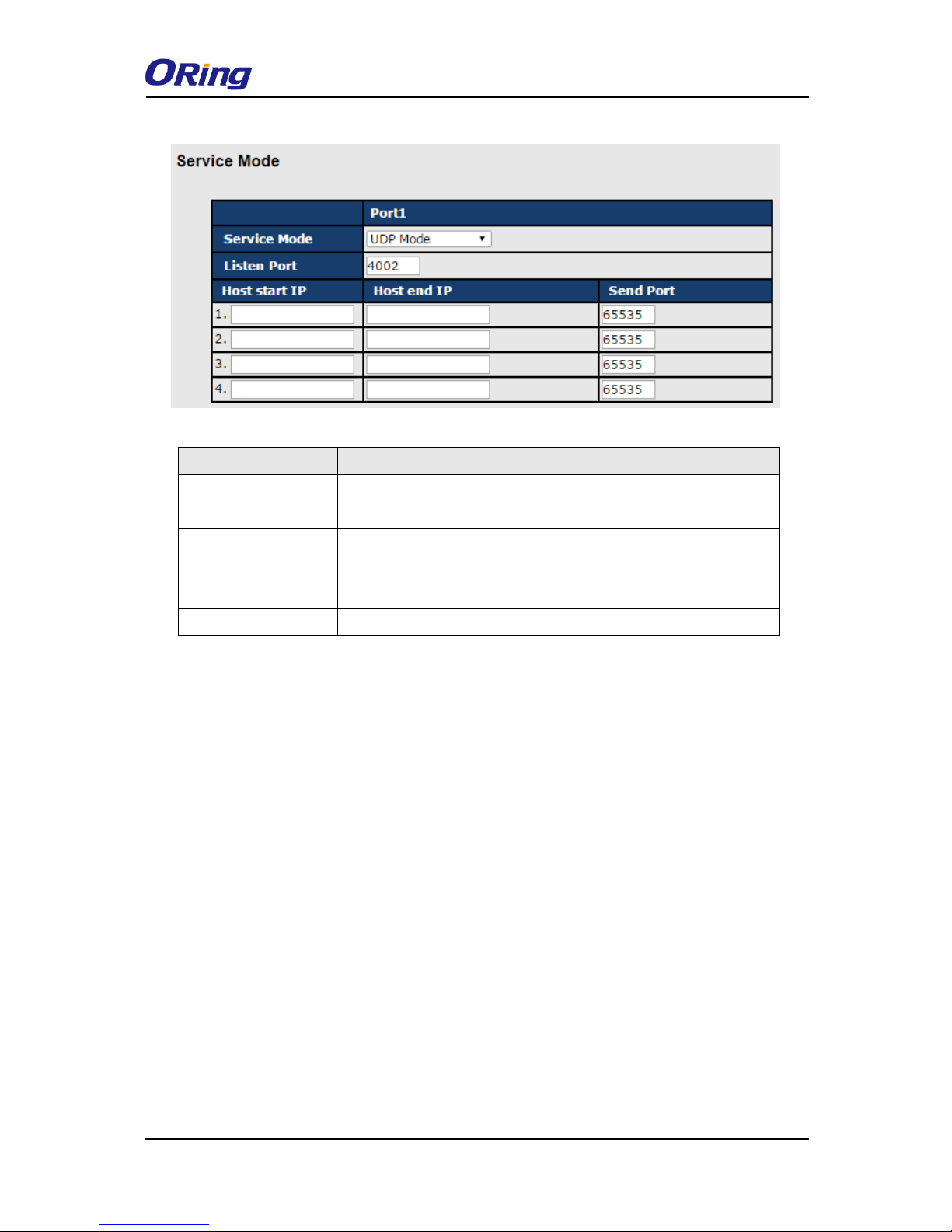
Service Mode – UDP Mode
Compared to TCP communications, UDP is faster and more efficient. In UDP mode, you can
uni-cast or multi-cast data from the serial device server to host computers, and the serial
device can also receive data from one or multiple host.
Page 45
IDS-4312(+) Series User Manual
ORing Industrial Networking Corp
44
Label
Description
Listen Port
Allows the user to set a new TCP port number to listen on rather
than the default value of the device
Host Start/End IP
If there are more than one destination hosts, specify the IP
address range by inputting a value in Host Start / End IP. You can
also auto scan the sending port number of the device.
Send Port
Set the send port number.
Management
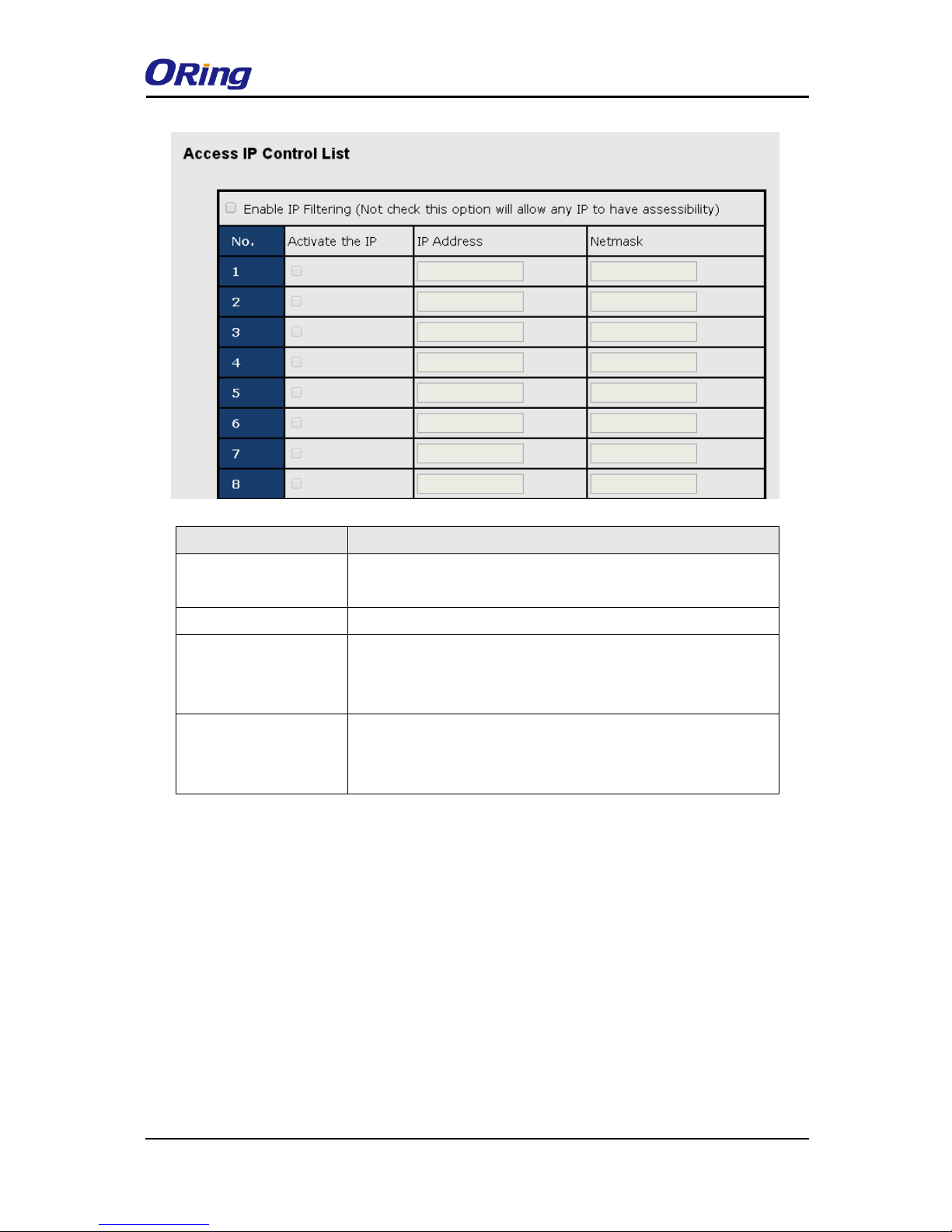
Access IP Control
Access IP Control List allows you to add or block remote host IP addresses to prevent
unauthorized access. If a host’s IP address is in the accessible IP table, the host will be
allowed to access the DS. You can check
Page 46
IDS-4312(+) Series User Manual
ORing Industrial Networking Corp
45
Label
Description
Enable IP Filtering
Leaving the box unchecked means any host can access the
device server.
Activate the IP
Check the box to activate the IP address.
IP Address
Only the host with the specified IP address can access the
device server. The format should be IP address
/255.255.255.255 (e.g., “192.168.0.1/255.255.255.255”).
Netmask
Only the host on the specified subnet can access the device
server. The format should be IP address /255.255.255.0 (e.g.,
“192.168.0.1/255.255.255.0”).
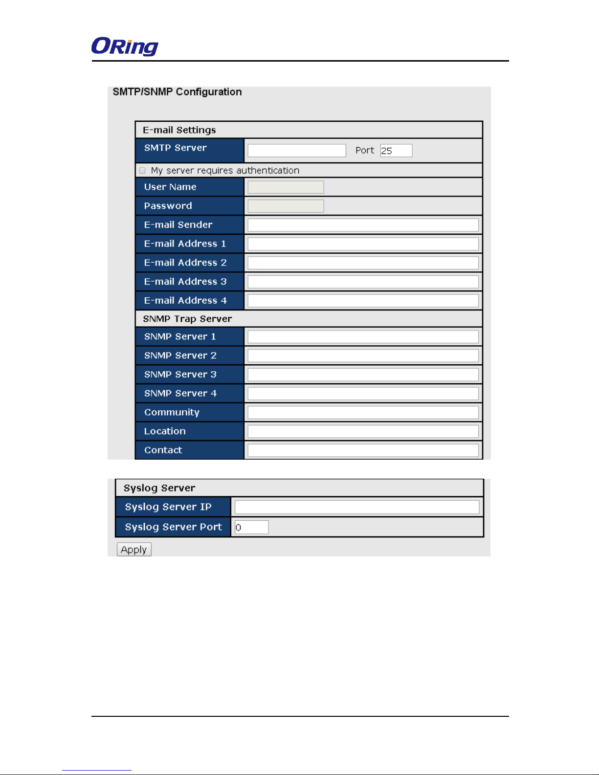
SMTP/SNMP Conf
Email server configurations include the mail server’s IP address or domain. If authentication is
required, you need to specify your username and password. You can set up to four email
addresses for receiving notifications.
SNMP server configurations include the SNMP trap server IP address, community, location
and contact. You can set up to four SNMP addresses you for receiving notifications.
Page 47
IDS-4312(+) Series User Manual
ORing Industrial Networking Corp
46
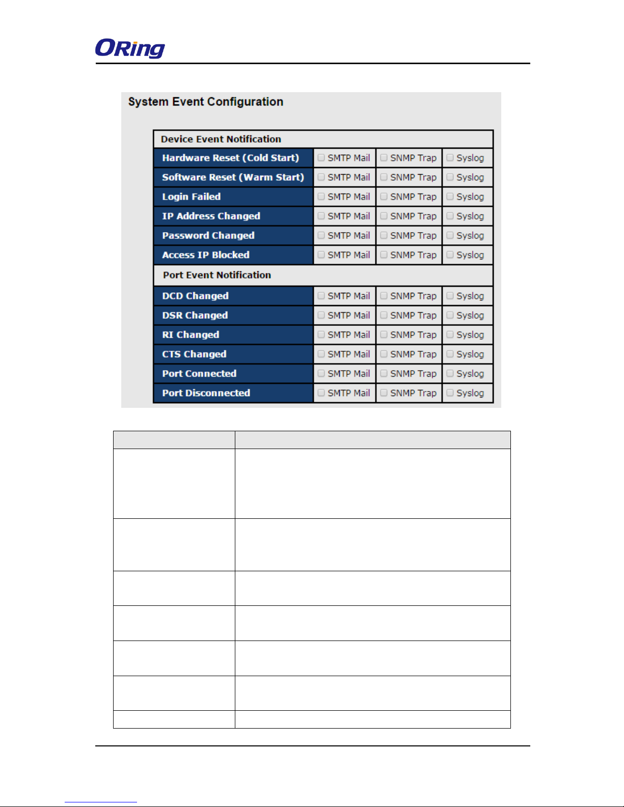
System Event Conf.
Specify the events that will be reported to the administrator. The notifications of the events can
be done via e-mail, SNMP trap, or system log.
Page 48
IDS-4312(+) Series User Manual
ORing Industrial Networking Corp
47
Label
Description
Hardware Reset (Cold
Start)
This refers to starting the system from power off (in contrast
with warm start). When performing a cold start, DS will
automatically issue an auto warning message via e-mail, logs,
or SNMP trap after booting.
Software Reset (Warm
Start)
This refers to restarting the computer without turning the power
off. When performing a warm start, DS will automatically send
an e-mail, log or SNMP trap after rebooting.
Login Failed
When unauthorized access from the console or Web interface
occurs, a notification will be sent.
IP Address Changed
When the IP address of the device is changed, a notification
will be sent.
Password Changed
When the password of the device is changed, a notification will
be sent.
Access IP Blocked
When the host accesses the device with a blocked IP address,
a notification will be sent.
DCD Changed
When a DCD (Data Carrier Detect) signal changes, indicating
Page 49
IDS-4312(+) Series User Manual
ORing Industrial Networking Corp
48
modem connection status has been changed, a notification will
be sent.
DSR Changed
When a DSR (Data Set Ready) signal changes, indicating data
communication equipment is powered off, a notification will be
sent.
RI Changed
When a RI (Ring Indicator) signal changes, indicating there is
an incoming call, a notification will be sent.
CTS Changed
When a CTS (Clear To Send) signal changes, indicating
transmission between computer and DCE can proceed, a
notification will be sent.
Port Connected
In TCP Server Mode, when the device accepts an incoming
TCP connection, this event will be triggered. In TCP Client
Mode, when the device has connected to the remote host, the
event will be triggered. In Virtual COM Mode, when Virtual
COM is ready to use, this event will be triggered. A notification
will be sent when an event is triggered.
Port Disconnected
In TCP Server/Client Mode, when the device loses the TCP
link, this event will be triggered. In Virtual COM Mode, when
Virtual COM is not available, this event will be triggered. A
notification will be sent when an event is triggered.
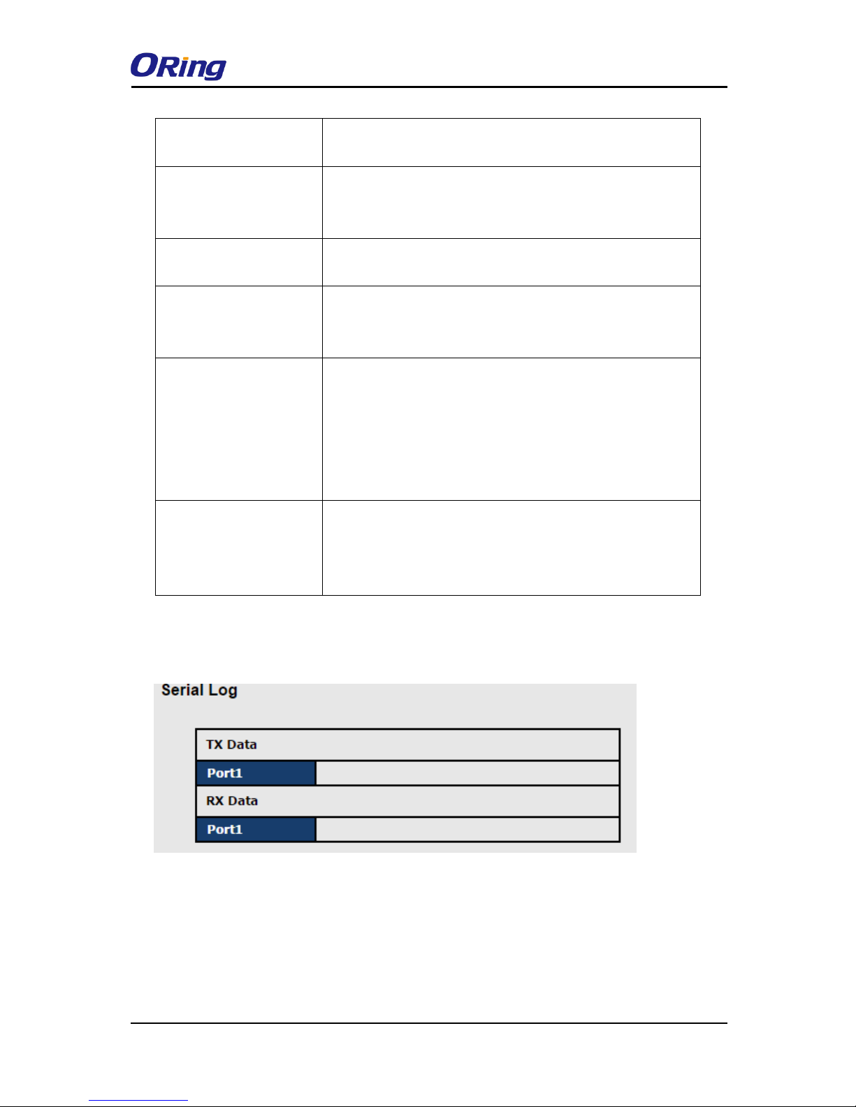
Serial Log
This page displays information with regard to data transmission and reception of each port.
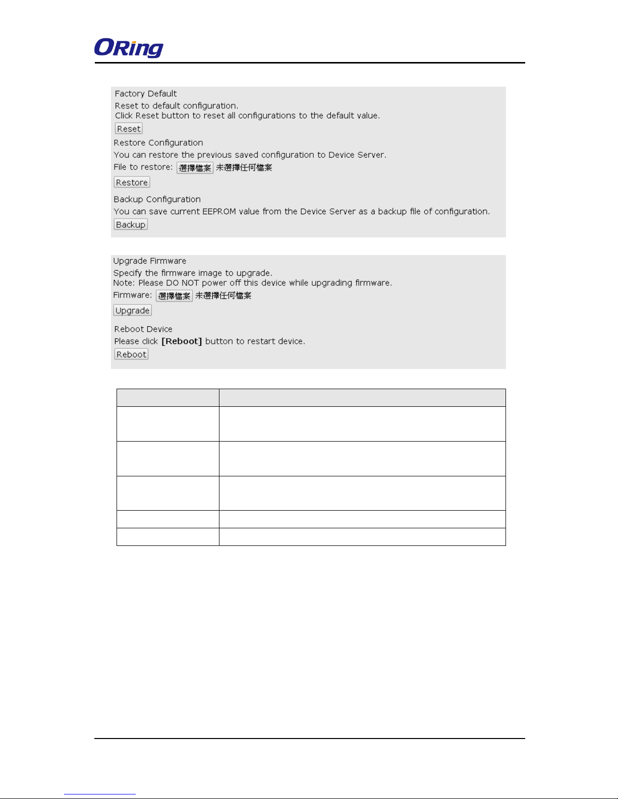
Save/Reboot
You can save current values from the device as a backup file or restore the device to previous
settings by downloading a configuration file. Simply browse to the configuration file you want to
use and click Restore.
Page 50
IDS-4312(+) Series User Manual
ORing Industrial Networking Corp
49
Label
Description
Factory Default
Press Reset for five seconds (Hardware restore) and it will load
default configurations to the system except the network settings..
Restore
Configuration
Restore to previous settings using previously exported
configurations.
Backup
Configuration
Export the current configuration to a file.
Upgrade Firmware
Upgrade to a new firmware by browsing to a specific folder.
Reboot Device
Reboot the device server (warm start).
4.3 Configuration by SSH Console
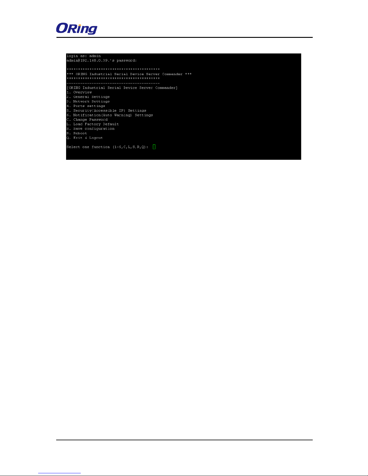
4.3.1 Connect to DS
You can use SSH Tool (e.g., PUTTY) to access the SSH console of the device. The SSH
console interface is shown below.
Page 51
IDS-4312(+) Series User Manual
ORing Industrial Networking Corp
50
Page 52
IDS-4312(+) Series User Manual
ORing Industrial Networking Corp
51
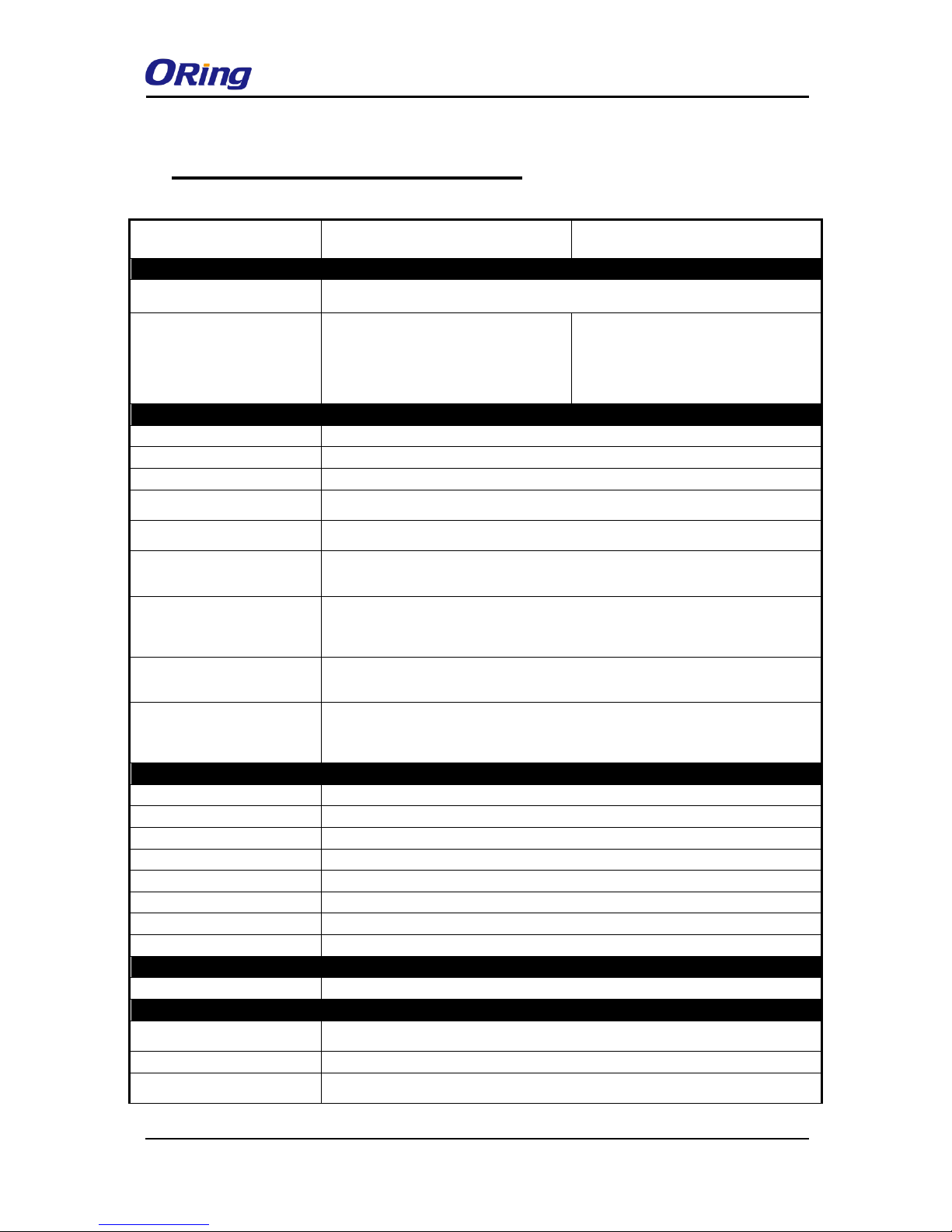
Technical Specifications
ORing Device Server Model
IDS-4312
IDS-4312+
Physical Ports
10/100 Base-T(X) Ports in RJ45
Auto MDI/MDIX
2
P.O.E. P.O.E.Present at ETH1
Power Device (IEEE 802.3af):
IEEE 802.3af compliant input interface
Over load & short circuit protection
Isolation Voltage: 1000 VDC min.
Isolation Resistance : 108 ohms min
WLAN feature
Operation Mode
Client
Antenna and Connector
1 x External reverse SMA-type antenna connector
Radio Frequency Type
DSSS, OFDM
Modulation
IEEE802.11b: CCK, DQPSK, DBPSK
IEEE802.11g/n: OFDM with BPSK, QPSK, 16QAM, 64QAM
Frequency Band
America / FCC: 2.412~2.462 GHz (11 channels )
Europe CE / ETSI: 2.412~2.472 GHz ( 13 channels )
Transmission Rate
802.11b: 1/2/5.5/11 Mbps
802.11g: 6/9/12/18/24/36/48/54 Mbps
802.11n(40MHz): UP to 150 Mbps
Transmit Power
802.11b: 13.5dBm ± 1.5dBm
802.11g: 13.5dBm ± 1.5dBm
802.11n(2.4G@20MHz): 13.5dBm ± 1.5dBm
802.11n(2.4G@40MHz): 13.5dBm ± 1.5dBm
Receive Sensitivity
802.11b: -90dBm ± 2dBm@1Mbps
802.11g: -72dBm ± 2dBm@54Mbps
802.11n(2.4G@40MHz,MCS7): -68dBm ± 2dBm
Encryption Security
WEP: (64-bit, 128-bit key supported)
WPA/WPA2:802.11i (WEP and AES encryption)
WPA-PSK (256-bit key pre-shared key supported)
802.1X Authentication supported
Serial Ports
Connector
DB9 x 1
Operation Mode
RS-232/422/485
Serial Baud Rate
110 bps to 460.8 Kbps
Data Bits
7, 8
Parity
odd, even, none, mark, space
Stop Bits
1, 1.5, 2
RS-232
TxD, RxD, RTS, CTS, DTR, DSR, DCD, RI, GND
Flow Control
XON/XOFF, RTS/CTS, DTR/DSR
Network Protocol
Protocol
ICMP, IP, TCP, UDP, DHCP, BOOTP, SSH, DNS, SNMP V1/V2c, HTTPS, SMTP
LED indicators
Power indicator
3 x LEDs, PWR 1(2)(PoE):
Green On: Power is on
10/100TX RJ45 port indicator
Green for port Link/Act at 100Mbps.
Serial TX / RX LEDs:
Red: Serial port is receiving data
Green: Serial port is transmitting data
Page 53
IDS-4312(+) Series User Manual
ORing Industrial Networking Corp
52
WLAN LED
WLAN Link /ACT: Green: Blinking
Power
Redundant Input power
Dual DC inputs. 12-48VDC on 6-pin terminal block
Power consumption (Typ.)
3.98 W
Overload current protection
Present
Reverse polarity protection
Present on terminal block
Physical Characteristic
Enclosure
IP-30
Dimension (W x D x H)
45 (W) x 81 (D) x 95 (H) mm
Weight (g)
322 g
331 g
Environmental
Storage Temperature
-40 to 85oC (-40 to 185oF)
Operating Temperature
-40 to 70oC (-40 to 158oF)
Operating Humidity
5% to 95% Non-condensing
Regulatory approvals
EMI
FCC Part 15, CISPR ( EN55022 Class A)
EMS
EN61000-4-2 (ESD)
EN61000-4-3 (RS)
EN61000-4-4 (EFT)
EN61000-4-5 (Surge)
EN61000-4-6 (CS)
EN61000-4-8
EN61000-4-11
Shock
IEC60068-2-27
Free Fall
IEC60068-2-32
Vibration
IEC60068-2-6
Safety
EN60950-1
Warranty
5 years
 Loading...