

Page 1
Industrial Device Server User’s Manual
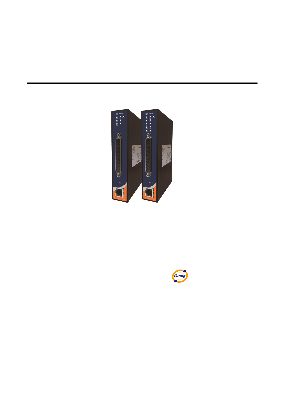
IDS-141A / IDS-181A
Version 1.00
January 2018.
ORing Industrial Networking Corp.
3F., No.542-2, Jhongjheng Rd., Sindian
District, New Taipei City 231- 48, Taiwan
Tel: + 886 2 2218 1066
Fax: + 886 2 2218 1014
Website :
E-mail : [email protected]
Page 2

Table of Content
GETTING TO KNOW YOUR DEVICE SERVER ............................................................................................... 1
1.1 About the IDS-141A / IDS-181A Serial Device Server ...................................................................... 1
1.2 Software Features ............................................................................................................................ 1
1.3 Hardware Features ........................................................................................................................... 2
HARDWARE INSTALLATION ....................................................................................................................... 3
2.1 Install IDS-141A / IDS-181A on DIN-Rail .......................................................................................... 3
2.1.1 Mount IDS-141A / IDS-181A on DIN-Rail ................................................................................................. 3
2.2 Wall Mounting Installation ................................................................................................................. 4
2.2.1 Mount IDS-141A / IDS-181A on wall ................................................................................................ ......... 5
HARDWARE OVERVIEW ............................................................................................................................ 7
3.1 Front Panel ....................................................................................................................................... 7
3.2 Front Panel LEDS ............................................................................................................................. 8
3.3 Serial Ports ....................................................................................................................................... 9
3.4 Bottom Panel .................................................................................................................................. 11
CABLES ................................................................................................................................................12
4.1 Ethernet Cables .............................................................................................................................. 12
MANAGEMENT INTERFACE .....................................................................................................................14
5.1 DS-Tool ........................................................................................................................................... 14
5.1.1 Install IDS-Tool ......................................................................................................................................... 14
5.1.2 Using DS-Tool ........................................................................................................................................... 16
5.1.2.1 Explore device servers .................................................................................................................... 16
5.1.2.2 Configure device servers ................................................................................................................. 17
5.1.2.3 Configure serial port ....................................................................................................................... 25
5.2 Configuration by Web Browser ....................................................................................................... 34
5.2.1 Connect to the Web page ........................................................................................................................... 34
5.2.1.1 System ............................................................................................................................................. 36
5.2.1.2 Port serial setting ............................................................................................................................. 39
5.2.1.3 Management .................................................................................................................................... 47
5.2.1.4 Save/Reboot .................................................................................................................................... 51
Page 3

IDS-141A_181A Series User’s Manual
5.3 Configuration by SSH Console ....................................................................................................... 52
5.3.1 Connect to DS ............................................................................................................................................ 52
TECHNICAL SPECIFICATIONS ..................................................................................................................53
Page 4

Page 5
IDS-141A_181A Series User’s Manual
1 ORing Industrial Networking Corp.
Getting to Know Your Device Server
1.1 About the IDS-141A / IDS-181A Serial Device Server
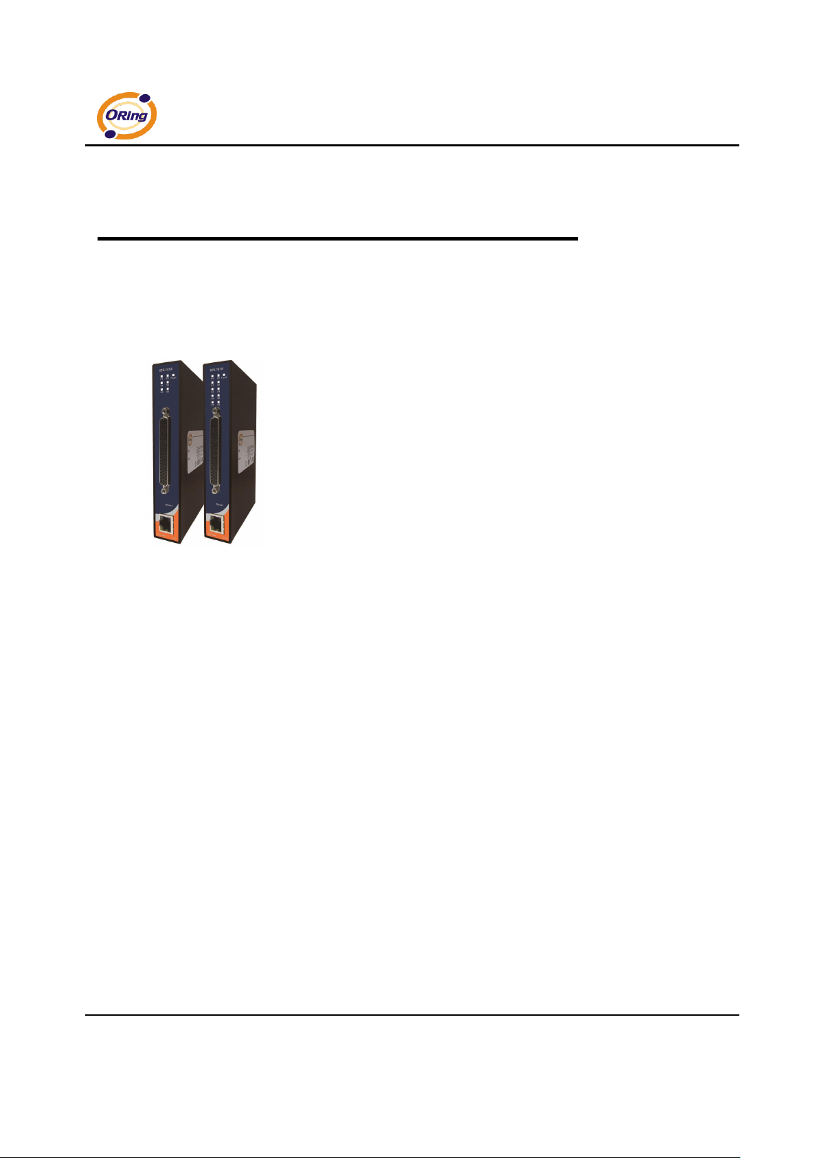
IDS-141A / IDS-181A is an innovative 4 & 8 ports RS232 to LAN device
server. Users are able to configure IDS-141A / IDS-181A by DS-Tool via
LAN port. IDS-141A / IDS-181A offers many powerful features for HW &
SW redundant functions.
IDS-141A / IDS-181A can simultaneously transfer data into 5 host PCs.
This feature can assure all critical data that saved in different host PCs to
avoid Ethernet break or host PCs failure.
Secondly, the IDS-141A / IDS-181A provides dual redundant power inputs on terminal block.
IDS-141A / IDS-181A also provides NAT pass through function so that users are able to
manage IDS-141A / IDS-181A inside or outside the NAT router. It is easy for different IP
domain users to use IDS-141A / IDS-181A. Therefore, IDS-141A / IDS-181A is the best
communication redundant solution for current application of serial devices.
1.2 Software Features
NAT-pass through: User can manage IDS-141A / IDS-181A through NAT router.
Redundant Power Inputs: 12~48VDC on terminal block. & power jack
Redundant multiple host devices: 5 simultaneous in Virtual COM, TCP Server, TCP Client
mode, and 4 simultaneous for UDP mode.
Secured Management by HTTPS and SSH.
Versatile Modes: Virtual Com, Serial Tunnel, TCP Server, TCP Client, UDP
Event Warning by Syslog, Email, SNMP trap, Relay
Various Windows O.S. supported: Windows NT/2000/ XP/ 2003/VISTA 32bits
Page 6

IDS-141A_181A Series User’s Manual
ORing Industrial Networking Corp 2.
1.3 Hardware Features
Redundant Power Inputs: 12~48 VDC on terminal block and power jack
Operating Temperature: -40 to 70
o
C
Storage Temperature: -40 to 85
o
C
Operating Humidity: 5% to 95%, non-condensing
Casing: IP-30
One 10/100Base-T(X) Ethernet port
Dimensions(W x D x H) : 26.1(W) x 94.9(D) x 144.3(H) mm
Page 7

IDS-141A_181A Series User’s Manual
3 ORing Industrial Networking Corp.
Hardware Installation
2.1 Install IDS-141A / IDS-181A on DIN-Rail
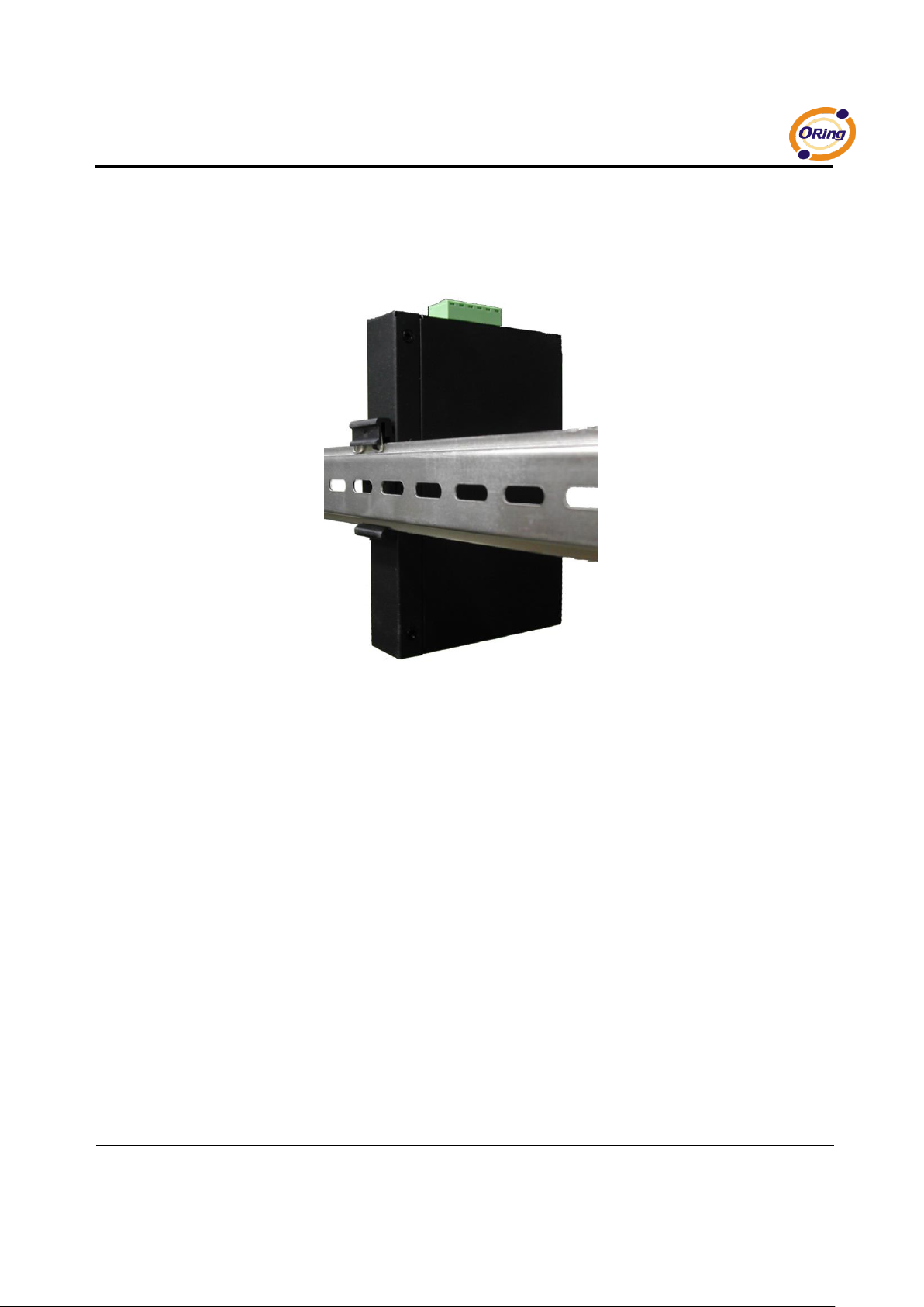
Each IDS-141A / IDS-181A has a Din-Rail kit on rear panel. The Din-Rail kit helps IDS-141A /
IDS-181A to fix on the Din-Rail. It is easy to install the IDS-141A / IDS-181A on the Din-Rail:
2.1.1 Mount IDS-141A / IDS-181A on DIN-Rail
Step 1: Slant the IDS-141A / IDS-181A and mount the metal spring to Din-Rail.
Figure 2-1
Metal Spring
Page 8
IDS-141A_181A Series User’s Manual
ORing Industrial Networking Corp 4.
Step 2: Push the IDS-141A / IDS-181A toward the Din-Rail until you heard a “click”
sound.
Figure 2-2
2.2 Wall Mounting Installation
Each IDS-141A / IDS-181A has another installation method for you. A wall mount panel can
be found in the package. The following steps show how to mount the IDS-141A / IDS-181A on
the wall:
Page 9
IDS-141A_181A Series User’s Manual
5 ORing Industrial Networking Corp.
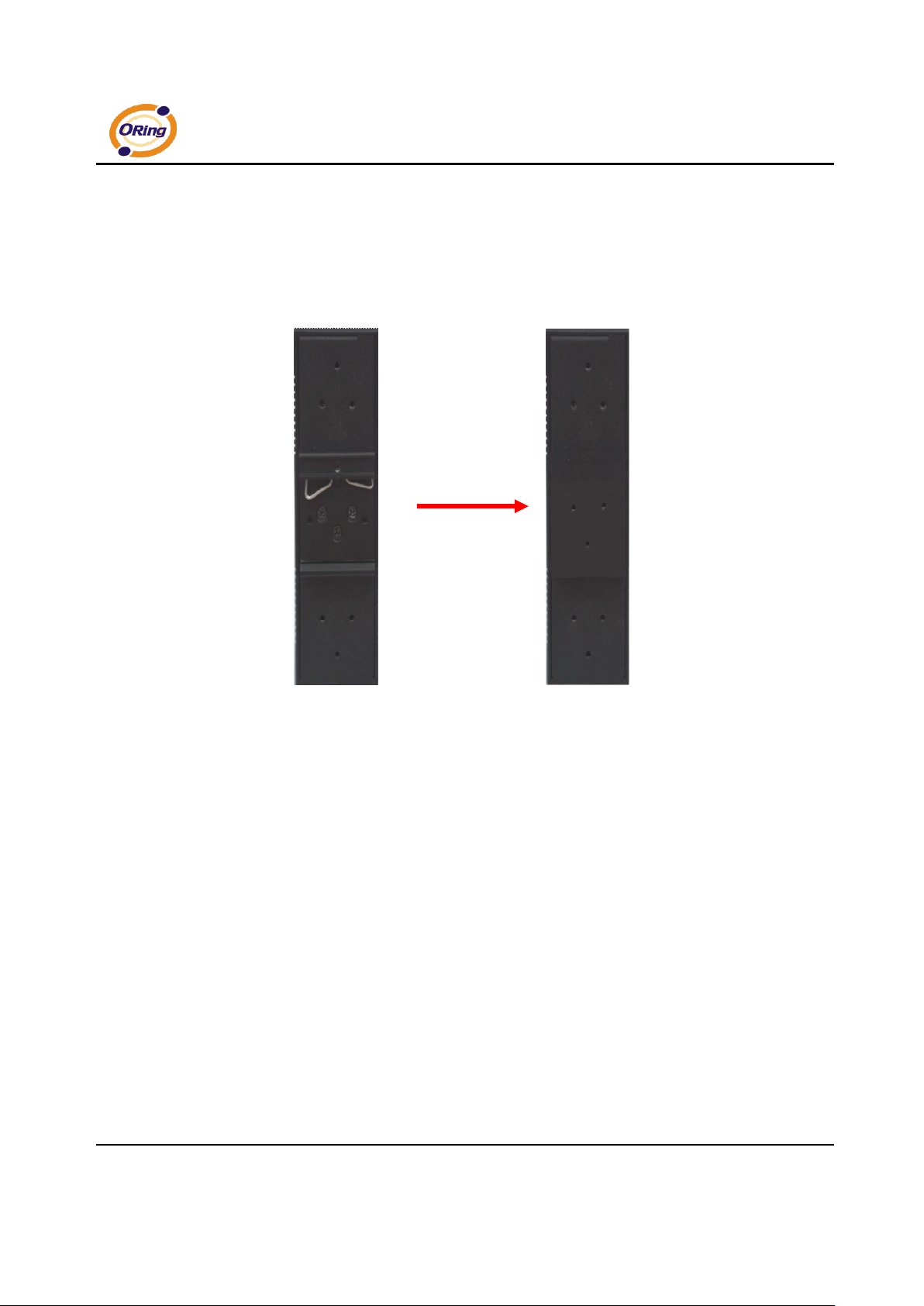
2.2.1 Mount IDS-141A / IDS-181A on wall
Step 1: Remove Din-Rail kit.
Figure 2-3
Page 10
IDS-141A_181A Series User’s Manual
ORing Industrial Networking Corp 6.
Pozidrive
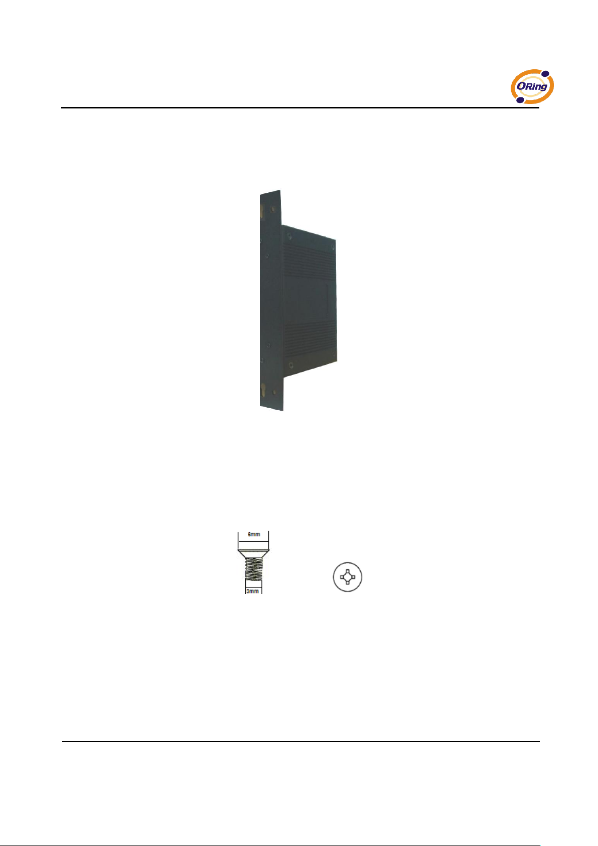
Step 2: Use 6 screws that can be found in the package to combine the wall mount panel.
Just like the picture shows below:
Figure 2-4
The screws specification shows in the following two pictures. In order to prevent IDS-141A
/ IDS-181A from any damage, the size of screws should not be larger than the size that
used in IDS-141A / IDS-181A.
Figure 2-5
Page 11
IDS-141A_181A Series User’s Manual
7 ORing Industrial Networking Corp.
Hardware Overview
3.1 Front Panel
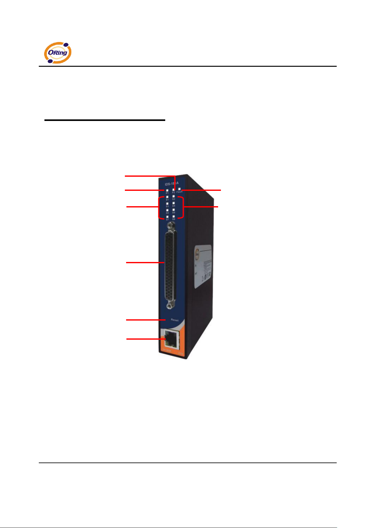
Figure 3-1
1. LED for PWR1 and system status. When the PWR1 links, the green LED will be light on.
2. LED for PWR2 and system status. When the PWR2 links, the green LED will be light on.
3. LED for fault indicator. When fault occurred, this red LED will be light on.
2
4 6 7 8 5 1 3
Page 12
IDS-141A_181A Series User’s Manual
ORing Industrial Networking Corp 8.
4. LED for Serial ports status. When data transmitted, the green LED will be light on. (S5~S8
only available for IDS-181A)
5. LED for Serial ports status. When data transmitted, the green LED will be light on. (S5~S8
only available for IDS-181A)
6. DB62 Female port.
7. Reset button, press for 10 sec for factory default.
8. 10/100Base-T(X) Ethernet port
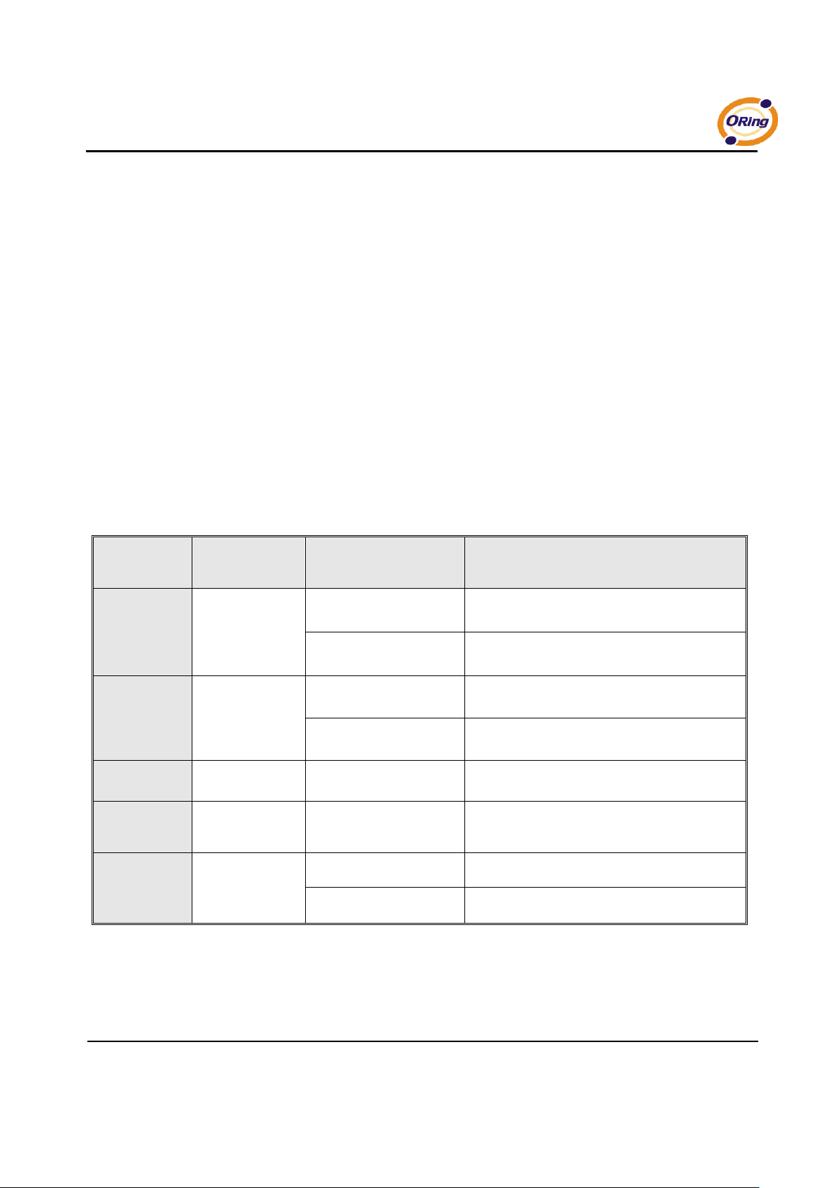
3.2 Front Panel LEDS
The following table describes the labels that stick on the IDS-141A / IDS-181A.
LED
Color
Status
Description
PWR1
Green
On
DC power 1 activated.
Blinking
System Booting / Located by administrator
PWR2
Green
On
DC power 2 activated.
Blinking
System Booting / Located by administrator
Fault
Amber
On
Fault event occurred.
S1 ~ S8
Green
Blinking
Serial port is transmitting/receiving
data(S5~S8 only available for IDS-181A)
ETH
Green/Amber
Green/Amber On/Blinking
100Mbps LNK/ACT
Green On/Blinking
10Mbps LNK/ACT
Table 3-1 Front panel LEDs
Page 13
IDS-141A_181A Series User’s Manual
9 ORing Industrial Networking Corp.
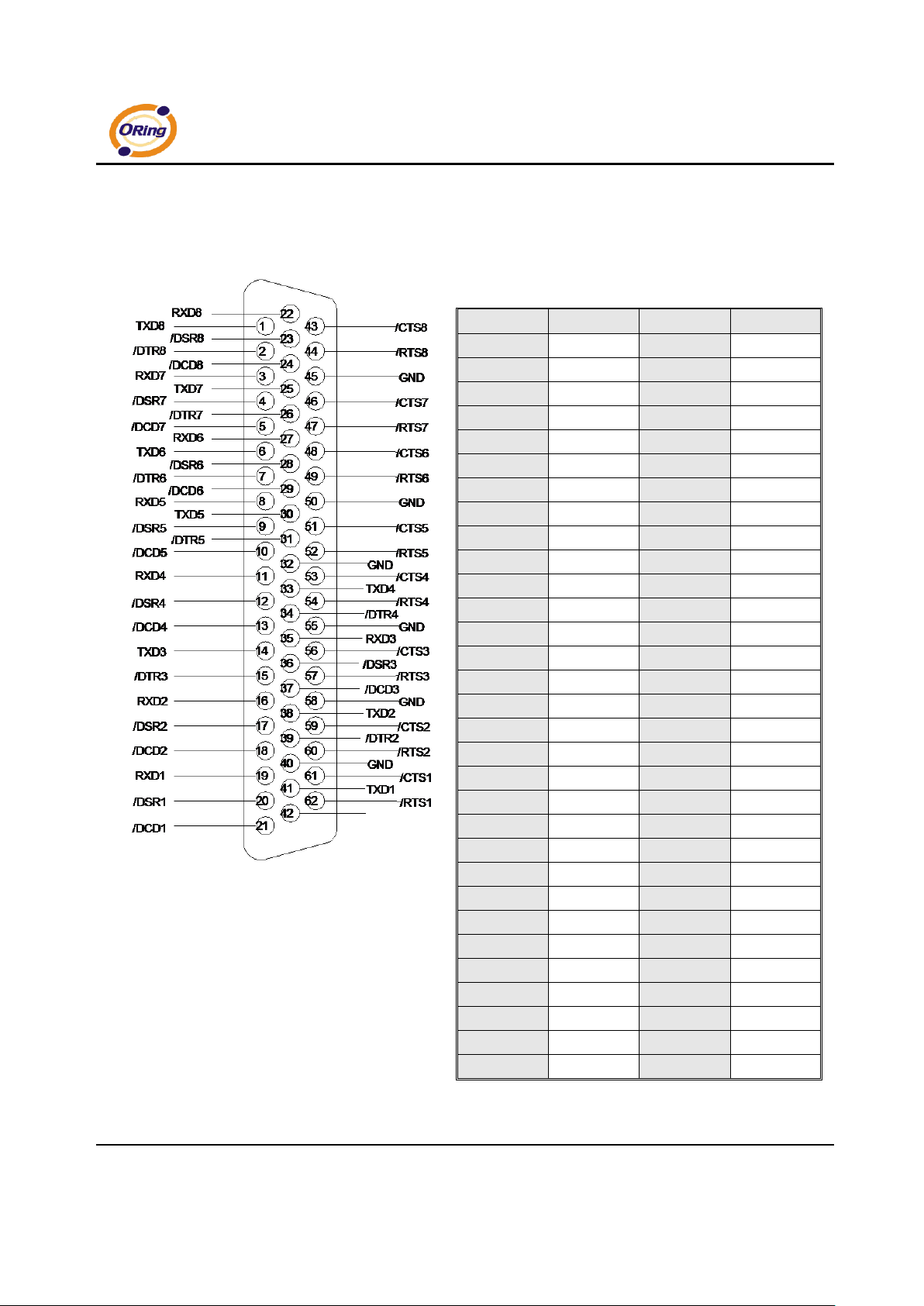
3.3 Serial Ports
There 8 serial ports on the front panel of IDS-141A / IDS-181A shown as below:
Pin #
RS 232
Pin #
RS 232
1
TXD8
32
GND
2
DTR8
33
TXD4
3
RXD7
34
DTR4
4
DSR7
35
RXD3
5
DCD7
36
DSR3
6
TXD6
37
DCD3
7
DTR6
38
Txd7
8
RXD5
39
DTR2
9
DSR5
40
GND
10
DCD5
41
TXD1
11
RXD4
42
DTR1
12
DSR4
43
CTS8
13
DCD4
44
RTS8
14
TXD3
45
GND
15
DTR3
46
CTS7
16
RXD2
47
RTS7
17
DSR2
48
CTS6
18
DCD2
49
RTS6
19
RXD1
50
GND
20
DSR1
51
CTS5
21
DCD1
52
RTS5
22
RXD8
53
CTS4
23
DSR8
54
RTS4
24
DCD8
55
GND
25
TXD7
56
CTS3
26
DTR7
57
RTS3
27
RXD6
58
GND
28
DSR6
59
CTS2
29
DCD6
60
RTS2
30
TXD5
61
CTS1
31
DTR5
62
RTS1
(S5~S8 only available for IDS-181A)
Page 14

IDS-141A_181A Series User’s Manual
ORing Industrial Networking Corp 10.
Table 3-2 Pin assignment
Page 15
IDS-141A_181A Series User’s Manual
11 ORing Industrial Networking Corp.
3.4 Bottom Panel
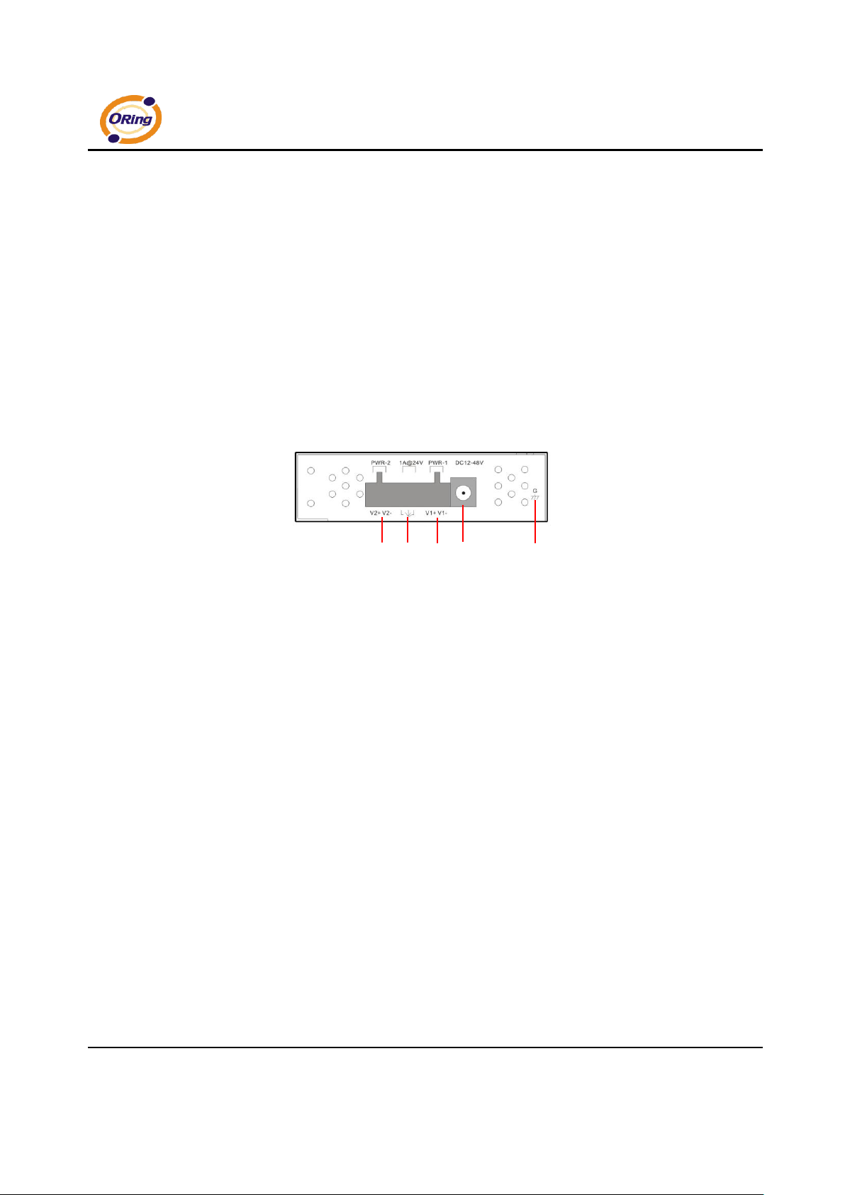
The bottom panel components of IUSB-9041 are shown as below:
1. Terminal block includes: PWR1 (12~48V DC).
2. Relay output (1A@24VDC).
3. Terminal block includes: PWR2 (12~48V DC).
4. Power Jack include: PWR2 (12 ~ 48V DC).
5. Frame ground.
Figure 3-2
1 3 2 4 5
Page 16
IDS-141A_181A Series User’s Manual
ORing Industrial Networking Corp 12.
Cables
4.1 Ethernet Cables
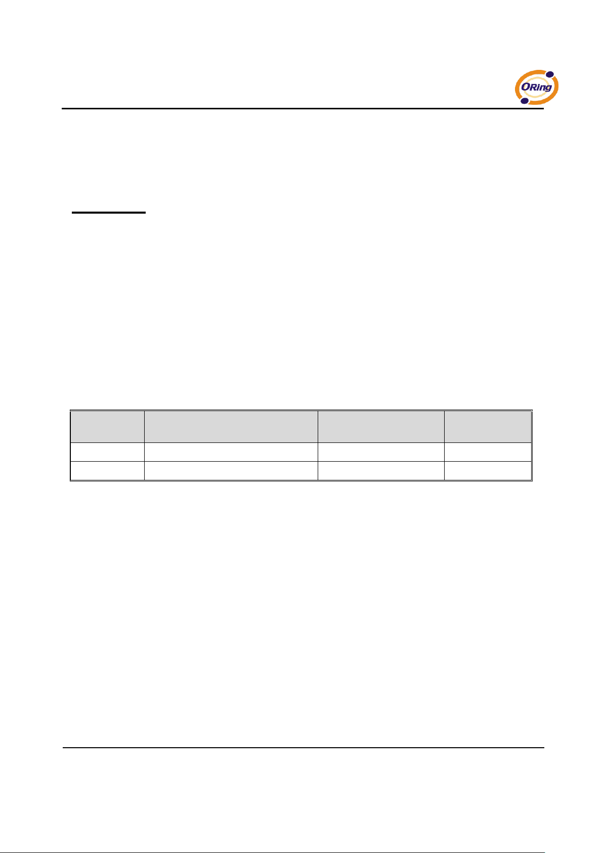
The IDS-141A / IDS-181A has standard Ethernet ports. According to the link type, the
IDS-141A / IDS-181A use CAT 3, 4, 5,5e UTP cables to connect to any other network device
(PCs, servers, switches, routers, or hubs). Please refer to the following table for cable
specifications.
Cable
Type
Max. Length
Connector
10BASE-T
Cat. 3, 4, 5 100-ohm
UTP 100 m (328 ft)
RJ-45
100BASE-TX
Cat. 5 100-ohm UTP
UTP 100 m (328 ft)
RJ-45
Table 4-1 Cable Types and Specifications
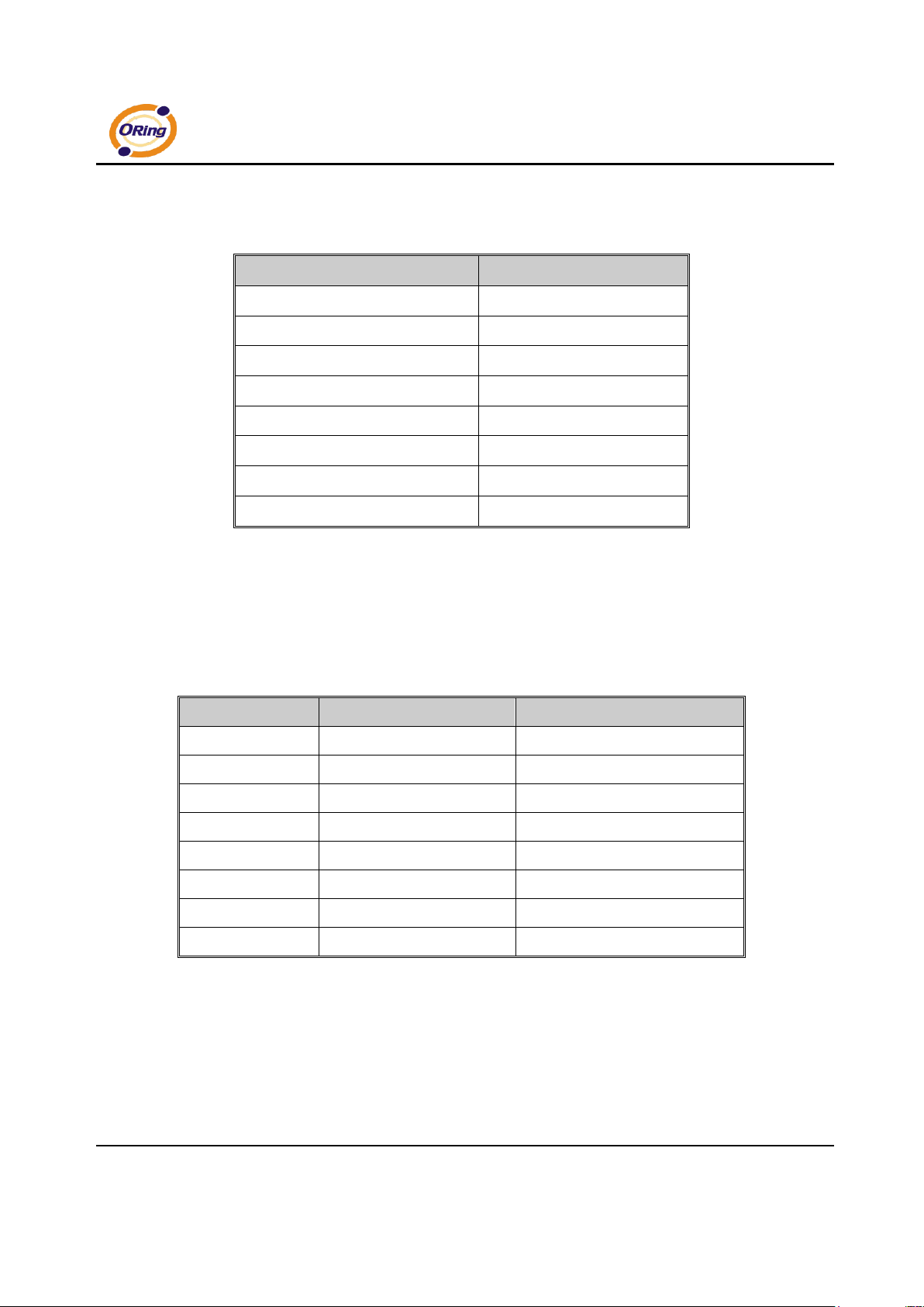
100BASE-TX/10BASE-T Pin Assignments
With 100BASE-TX/10BASE-T cable, pins 1 and 2 are used for transmitting data, and pins 3
and 6 are used for receiving data.
Page 17
IDS-141A_181A Series User’s Manual
13 ORing Industrial Networking Corp.
Pin Number
Assignment
1
TD+ 2 TD- 3 RD+
4
Not used
5
Not used
6
RD-
7
Not used
8
Not used
Table 4-2 RJ-45 Pin Assignments
The IDS-141A / IDS-181A supports auto MDI/MDI-X operation. You can use a straightthrough cable to connect PC to IDS-141A / IDS-181A. The following table below shows the
10BASE-T/ 100BASE-TX MDI and MDI-X port pin outs.
Pin Number
MDI port
MDI-X port
1
TD+(transmit)
RD+(receive)
2
TD-(transmit)
RD-(receive)
3
RD+(receive)
TD+(transmit)
4
Not used
Not used
5
Not used
Not used
6
RD-(receive)
TD-(transmit)
7
Not used
Not used
8
Not used
Not used
Table 4-2 MDI / MDI-X pins assignment
Note: “+” and “-” signs represent the polarity of the wires that make up each wire pair.
Page 18
IDS-141A_181A Series User’s Manual
ORing Industrial Networking Corp 14.
Management Interface
5.1 DS-Tool
DS-Tool is a powerful Windows utility for DS series. It supports device discovery, device
configuration, group setup, group firmware update, monitoring functions...etc. It is easy for
you to install and configure devices over the network.
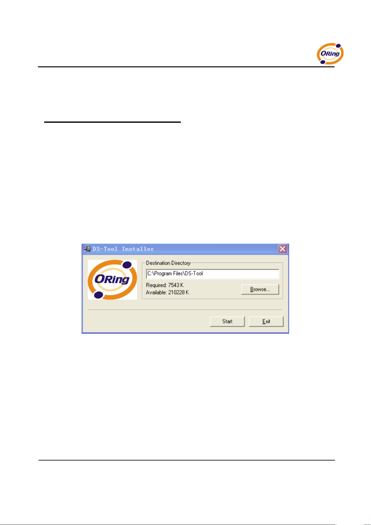
5.1.1 Install IDS-Tool
Step 1: Execute the Setup program, click “start” after selecting the folder for DS-Tool.
Figure 5-1
Page 19
IDS-141A_181A Series User’s Manual
15 ORing Industrial Networking Corp.
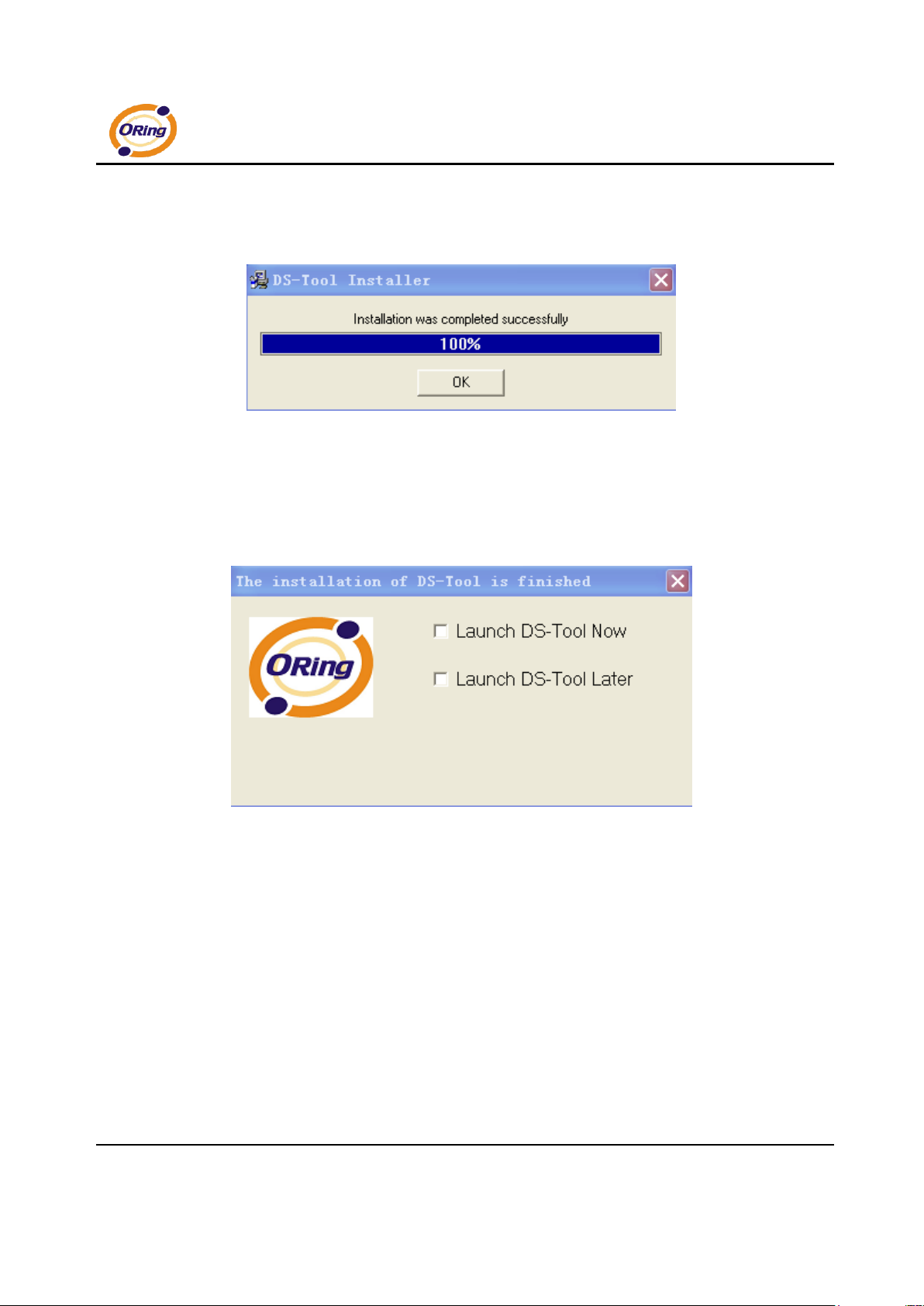
Step 2: When installation complete successfully, then click “OK”.
Figure 5-2
Step 3: Check for your selection.
Figure 5-3
Page 20
IDS-141A_181A Series User’s Manual
ORing Industrial Networking Corp 16.
5.1.2 Using DS-Tool
5.1.2.1 Explore device servers
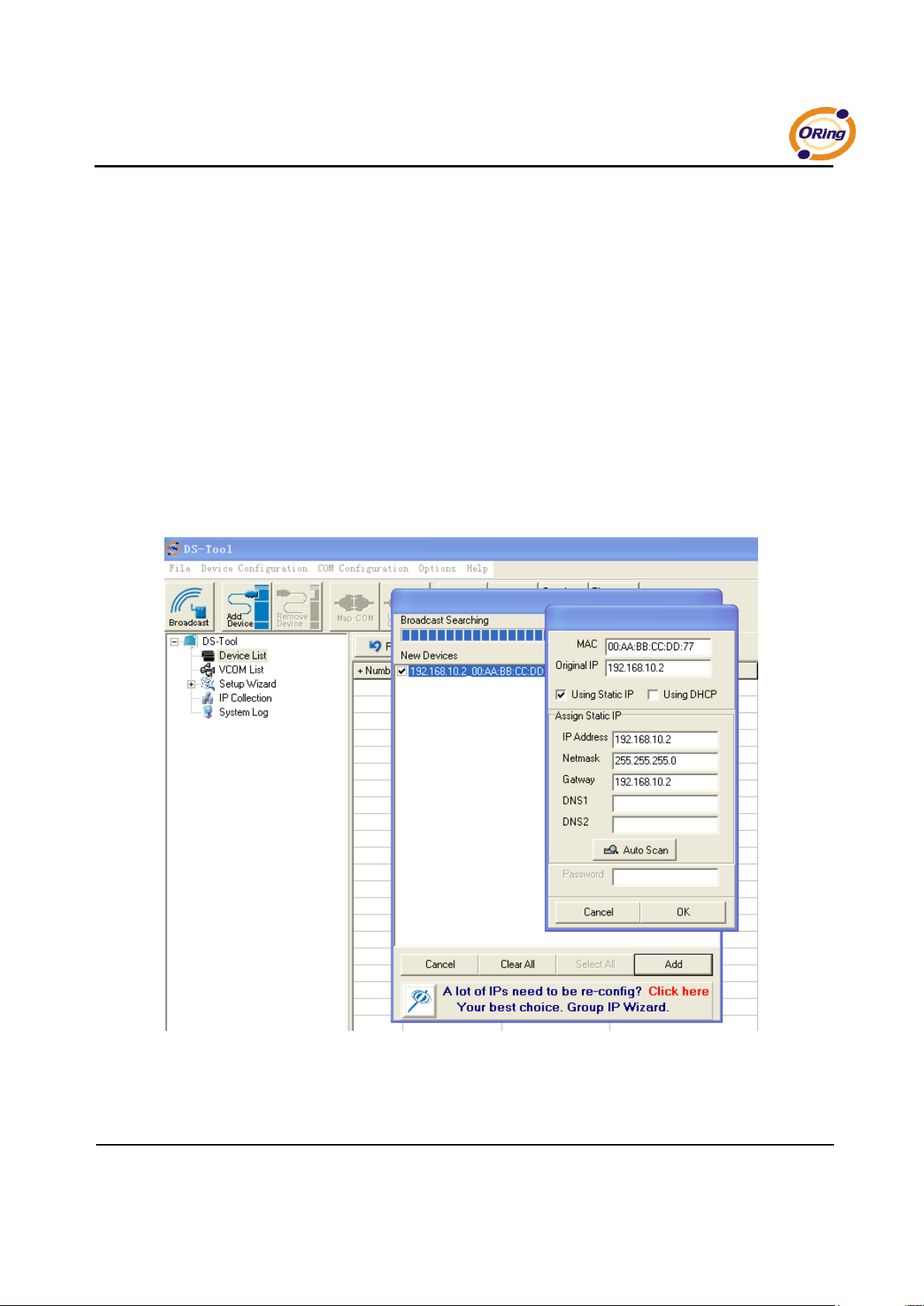
DS-Tool will broadcast to the network and search all available DS devices in the
network. The default IP address of device is “192.168.10.2”, and selects the
searching device you wish to use and press “Add” button.
You can set static IP address or in DHCP client mode to get IP address automatically.
Finally, click “OK “button to add the device.
Figure 5-4
Page 21
IDS-141A_181A Series User’s Manual
17 ORing Industrial Networking Corp.
5.1.2.2 Configure device servers
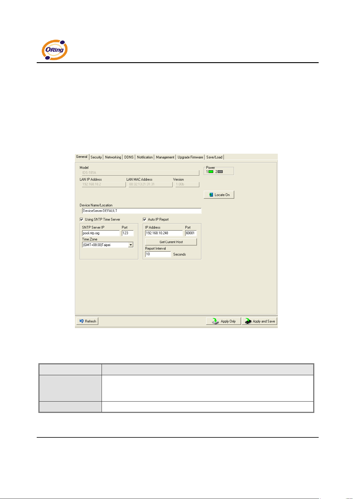
General settings
This page includes the setting of device name, SNTP server and Auto IP
Report.
Figure 5-5 General settings
The following table describes the labels in this screen.
Label
Description
Device Name/location
You can set the device name or related information. By clicking “Locate On” button you
can locate the serial server’s position.
Set SNTP
Input the SNTP server domain name or IP address, port and select the Time zone.
Page 22
IDS-141A_181A Series User’s Manual
ORing Industrial Networking Corp 18.
Set Auto IP Report
By Clicking the “Get current Host” button you will get your local IP, and then set the
Report interval time. The device server will report its status periodically.
Table 5-1 General settings
At IP collection option show the device server status. The report interval is 0 indicate
disable this setting (default). But you can set the other IP or Port.
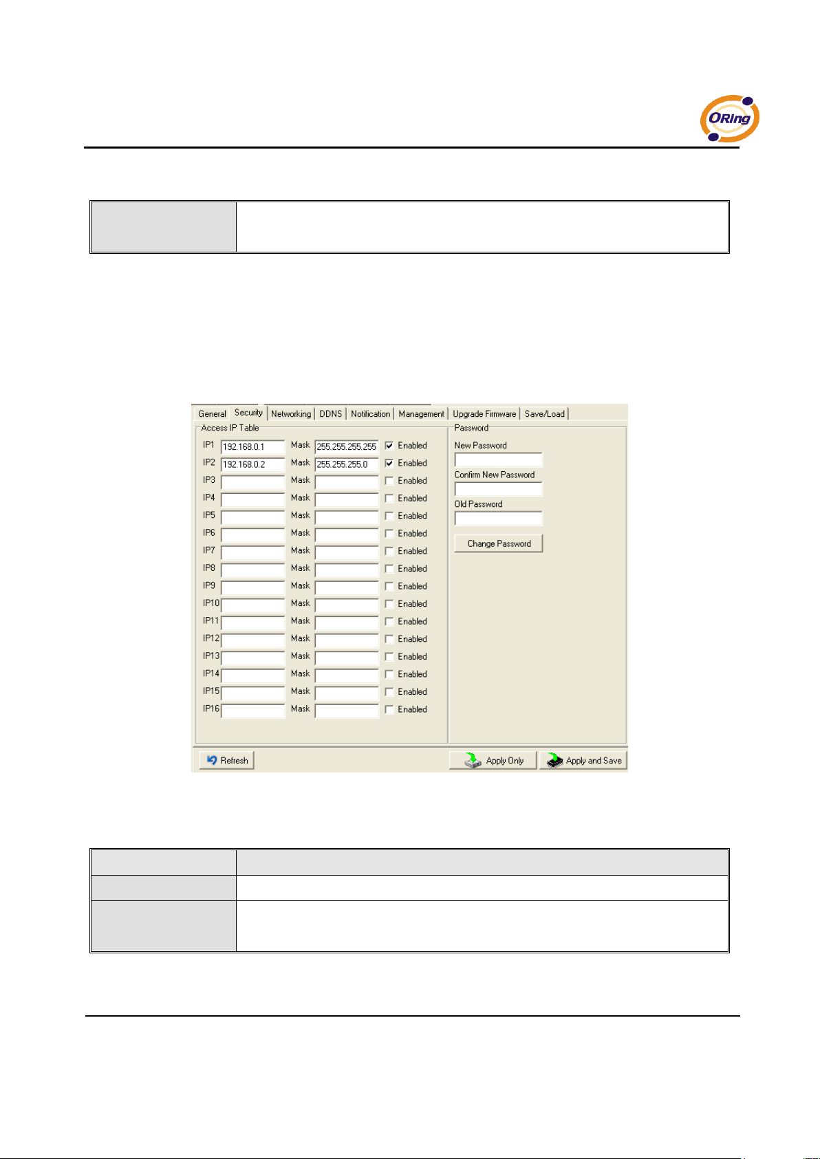
Security
Figure 5-6 Security
The following table describes the labels in this screen.
Label
Description
Accessible IP Setting
To prevent unauthorized access by setting host IP addresses and network masks.
Password setting
You can set the password to prevent unauthorized access from your server. Factory
default is no password.
Table 5-2 Security
Page 23
IDS-141A_181A Series User’s Manual
19 ORing Industrial Networking Corp.
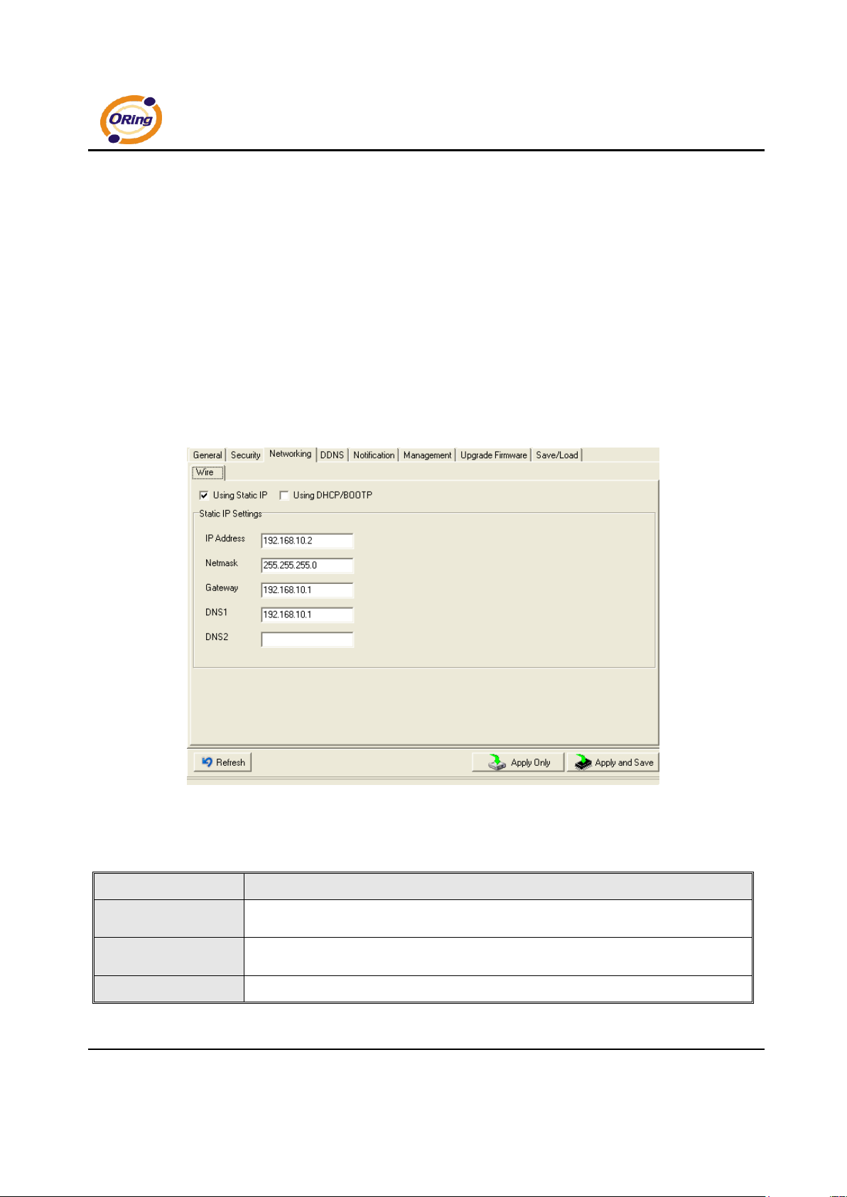
Network Setting
Device DS can connect the Network by wire a. You must assign a valid IP address
for DS before attached in your network environment. Your network administrator
should provide you the IP address and related settings. The IP address must be
unique within the network (otherwise, DS will not have a valid connection to the
network). You can choose from three possible “IP configuration” modes: Static,
DHCP/BOOTP. The Factory Default IP address is “192.168.10.2”
Figure 5-7 Network Setting
The following table describes the labels in this screen.
Label
Description
Using DHCP/BOOTP
IP Address automatically assigned by a DHCP server in your network.
Static IP Address
Manually assigning an IP address.
Subnet Mask
All devices on the network must have the same subnet mask to communicate on the
Page 24
IDS-141A_181A Series User’s Manual
ORing Industrial Networking Corp 20.
network.
Gateway
Enter the IP address of the router in you network.
DNS Server
Enter the IP address of the DNS server, The DNS server translates domain names into
IP address.
Table 5-3 Network setting
Page 25
IDS-141A_181A Series User’s Manual
21 ORing Industrial Networking Corp.
The following table describes the labels in this screen.
Label
Description
Service Provider
Choose the DDNS service Provider
Hostname
You must first apply an account from the DDNS service Provider such as www.dyndns.org,
then register with the dynamic DNS service. Input the fixed hostname you got from the
DDNS service.
Account mand
Password
Input the Account and Password you have registered from the DDNS service Provider.
Check WAN IP
Schedule
Device will check the IP address Status at interval time you set.
Table 5-4 DDNS setting
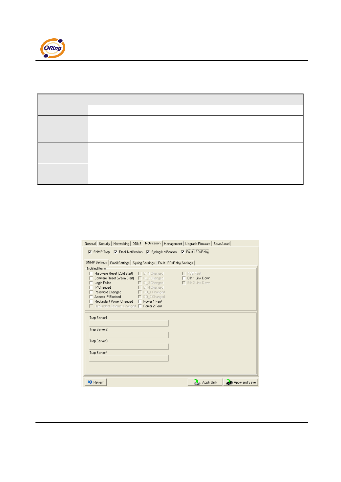
Notification
Specify the events that should be notified to the administrator. The events can
be alarmed by E-mail, SNMP trap, or system log.
Figure 5-9 Notification
Page 26
IDS-141A_181A Series User’s Manual
ORing Industrial Networking Corp 22.
The following table describes the labels in this screen.
Label
Description
SNMP Trap
To notify events by SNMP trap.
Email Notification
To notify events by Email.
Syslog Notification
To notify events by Syslog.
Fault LED /Relay Settings
To notify events by Fault LED and relay..
Notify items
Events to be notified.
Apply
Apply current setting.
Apply and Save
Apply and save current setting.
Table 5-3 Notification
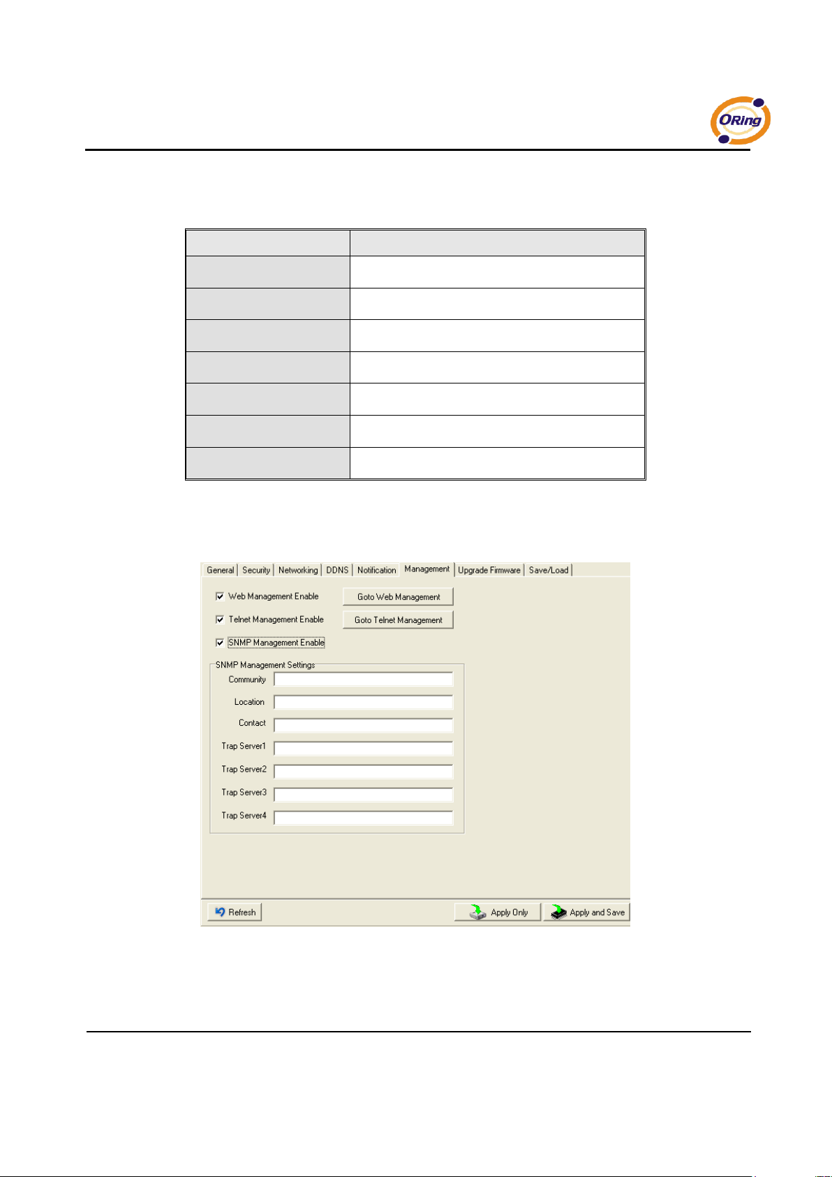
Management
Figure 5-10 Management
Page 27
IDS-141A_181A Series User’s Manual
23 ORing Industrial Networking Corp.
The following table describes the labels in this screen.
Label
Description
Web Management Enable
To enable management from Web. Click “Goto Web Management” button to
access web.
Telnet Management Enable
To enable management by Telnet.
SNMP Management Enable
To enable management by SNMP.
SNMP Management Settings
To configure SNMP related settings.
Table 5-4 Management
Upgrade Firmware
Figure 5-11 Upgrade Firmware
The following table describes the labels in this screen.
Label
Description
Browsing
Browse the file and upgrade
Upgrade
Enable the firmware upgrade.
Table 5-5 Upgrade Firmware
Page 28
IDS-141A_181A Series User’s Manual
ORing Industrial Networking Corp 24.
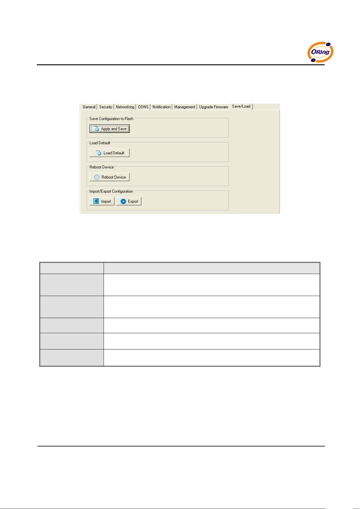
Save/Load
Figure 5-12 Save / Load
The following table describes the labels in this screen.
Label
Description
Save Configuration to
Flash
Save current configuration into flash memory.
Load Default
Load default configuration except the network settings. If you want to load all factory
default, you need to press “Reset” button on the device (Hardware restore).
Reboot Device
Reboot the device server (warm start).
Import Configuration
Restore the previous exported configuration.
Export Configuration
Exported current configuration to a file to backup the configuration.
Table 5-6 Save / Load
Page 29
IDS-141A_181A Series User’s Manual
25 ORing Industrial Networking Corp.
5.1.2.3 Configure serial port
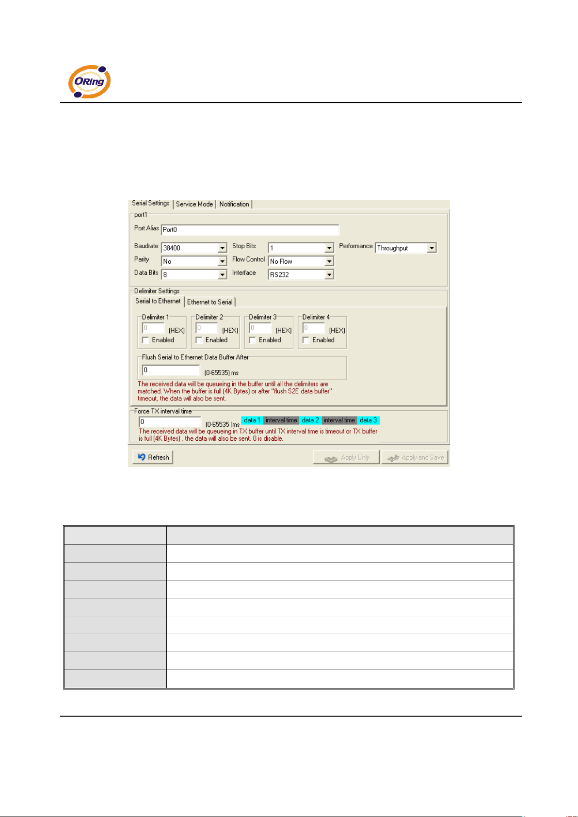
Serial Settings
Figure 5-13 Serial Settings
The following table describes the labels in this screen.
Label
Description
Port Alias
Remark the port to hint the connected device.
Interface
RS232
Baud rate
1200bps/2400bps/4800bps/9600bps/19200bps/ 38400bps/57600bps/115200bps
Data Bits
7, 8
Stop Bits
1, 2 (1.5)
Parity
No, Even, Odd, Mark, Space
Flow Control
No, XON/XOFF, RTS/CTS, DTR/DSR
Performance
Throughput: This mode optimized for highest transmission speed.
Page 30
IDS-141A_181A Series User’s Manual
ORing Industrial Networking Corp 26.
Latency: This mode optimized for shortest response time.
Serial to Ethernet
Delimiter:
You can define max. 4 delimiters (00~FF, Hex) for each way. The data will be
hold until the delimiters are received or the option “Flush Serial to Ethernet data
buffer” times out. 0 means disable. Factory default is 0.
Flush Data Buffer After:
The received data will be queuing in the buffer until all the delimiters are matched.
When the buffer is full (4K Bytes) or after "flush S2E data buffer" timeout the data will
also be sent. You can set the time from 0 to 65535 seconds.
Ethernet to Serial
Delimiter:
You can define max. 4 delimiters (00~FF, Hex) for each way. The data will be
hold until the delimiters are received or the option “Flush Ethernet to Serial data
buffer” times out. 0 means disable. Factory default is 0.
Flush Data Buffer After:
The received data will be queuing in the buffer until all the delimiters are
matched. When the buffer is full (4K Bytes) or after "flushE2S data buffer"
timeout the data will also be sent. You can set the time from 0 to 65535 seconds.
Page 31
IDS-141A_181A Series User’s Manual
27 ORing Industrial Networking Corp.
Force TX Interval Time
Force TX interval time is to specify the timeout when no data has been transmitted.
When the timeout is reached or TX buffer is full (4K Bytes), the queued data will be sent.
0 means disable. Factory default value is 0.
Table 5-7 Serial settings
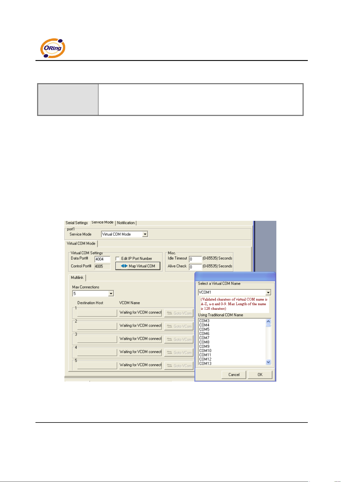
Service Mode – Virtual COM Mode
In Virtual COM Mode, The driver establishes a transparent connection between host
and serial device by mapping the Port of the serial server serial port to local COM
port on the host computer. Virtual COM Mode also supports up to 5 simultaneous
connections, so that multiple hosts can send or receive data by the same serial
device at the same time.
Figure 5-14 Virtual COM
Page 32
IDS-141A_181A Series User’s Manual
ORing Industrial Networking Corp 28.
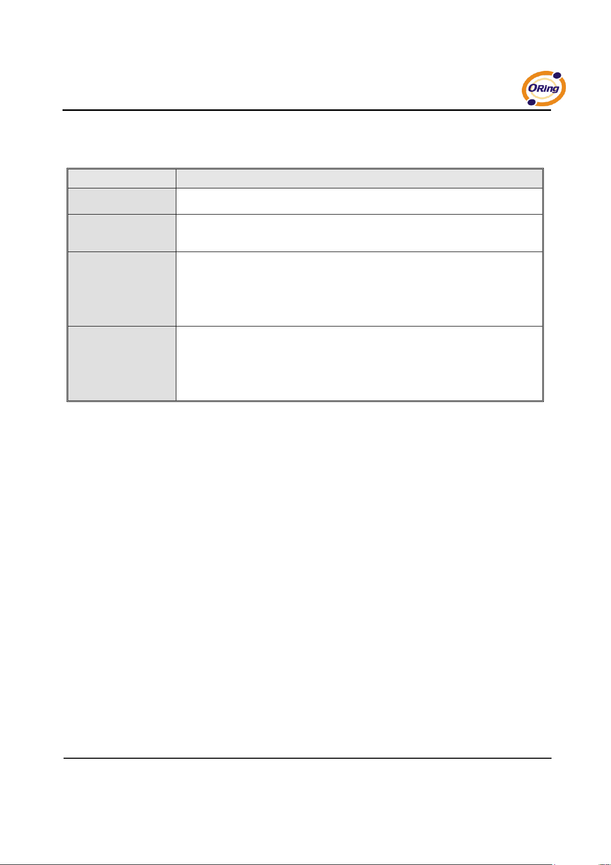
The following table describes the labels in this screen.
Label
Description
Map Virtual COM
Select a Virtual COM Name to map on.
Max Connection
The number of Max connection can support simultaneous connections are 5, default
values is 1.
Idle Timeout
When serial port stops data transmission for a defined period of time (Idle Timeout), the
connection will be closed and the port will be freed and try to connect with other hosts. 0
indicate disable this function. Factory default value is 0. If Multilink is configured, only
the first host connection is effective for this setting.
Alive Check
The serial device will send TCP alive-check package in each defined time interval (Alive
Check) to remote host to check the TCP connection. If the TCP connection is not alive,
the connection will be closed and the port will be freed. 0 indicate disable this function.
Factory default is 0.
Table 5-8 Virtual COM
*Not allowed to mapping Virtual COM from web
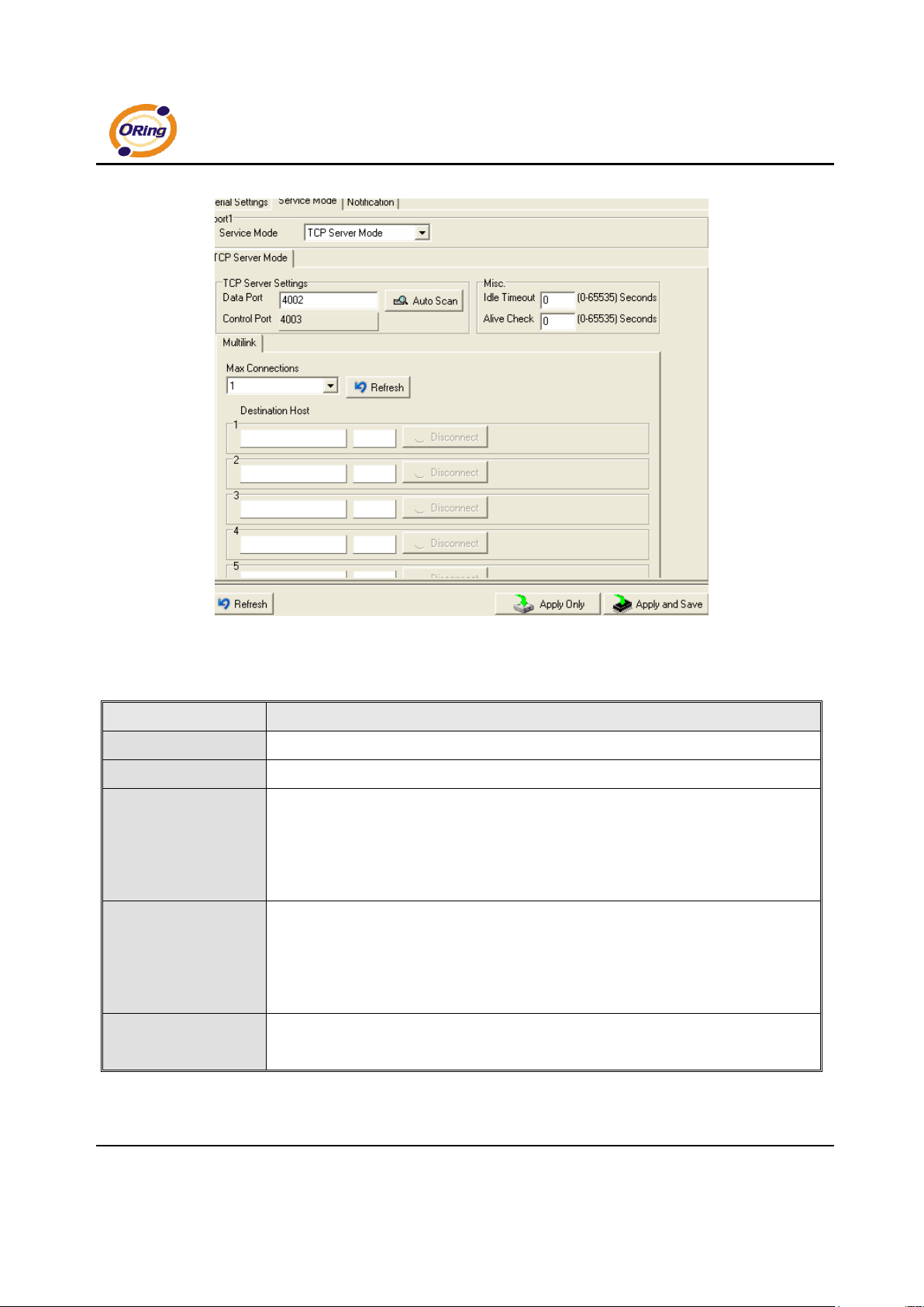
Service Mode – TCP Server Mode
In TCP Server Mode, DS is configured with a unique Port combination on a TCP/IP
network. In this case, DS waits passively to be contacted by the device. After a
connection is established, it can then proceed with data transmission. TCP Server
mode also supports up to 5 simultaneous connections, so that multiple device can
receive data from the same serial device at the same time.
Page 33
IDS-141A_181A Series User’s Manual
29 ORing Industrial Networking Corp.
Figure 5-15 TCP Server mode
The following table describes the labels in this screen.
Label
Description
Data Port
Set the port number for data transmission.
Auto Scan
Scan the data port automatically.
Idle Timeout
When serial port stops data transmission for a defined period of time (Idle Timeout), the
connection will be closed and the port will be freed and try to connect with other hosts.
0 indicate disable this function. Factory default value is 0. If Multilink is configured,
only the first host connection is effective for this setting.
Alive Check
The serial device will send TCP alive-check package in each defined time interval (Alive
Check) to remote host to check the TCP connection. If the TCP connection is not
alive, the connection will be closed and the port will be freed. 0 indicate disable this
function. Factory default is 0.
Max Connection
The number of Max connection can support simultaneous connections are 5, default
values is 1.
Table 5-9 TCP Server mode
Page 34
IDS-141A_181A Series User’s Manual
ORing Industrial Networking Corp 30.
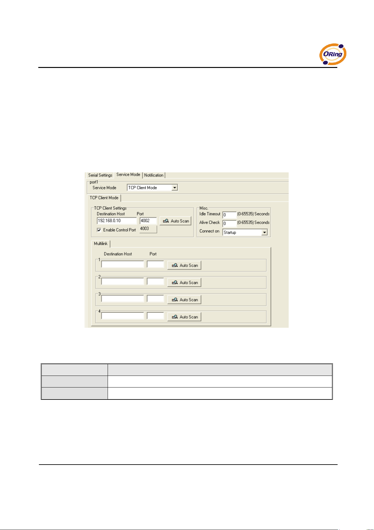
Service Mode – TCP Client Mode
In TCP Client Mode, device can establish a TCP connection with server by the
method you have settled (Startup or any character). After the data has been
transferred, device can disconnect automatically from the server by using the
TCP alive check time or Idle time settings.
Figure 5-16 TCP Client mode
The following table describes the labels in this screen.
Label
Description
Destination Host
Set the IP address of host.
Port
Set the port number of data port.
Page 35
IDS-141A_181A Series User’s Manual
31 ORing Industrial Networking Corp.
Idle Timeout
When serial port stops data transmission for a defined period of time (Idle
Timeout), the connection will be closed and the port will be freed and try to
connect with other hosts. 0 indicate disable this function. Factory default
value is 0. If Multilink is configured, only the first host connection is effective
for this setting.
Alive Check
The serial device will send TCP alive-check package in each defined time
interval (Alive Check) to remote host to check the TCP connection. If the TCP
connection is not alive, the connection will be closed and the port will be freed.
0 indicate disable this function. Factory default is 0.
Connect on Startup
The TCP Client will build TCP connection once the connected serial device is
started.
Connect on Any
Character
The TCP Client will build TCP connection once the connected serial device
starts to send data.
Table 5-10 TCP Client mode
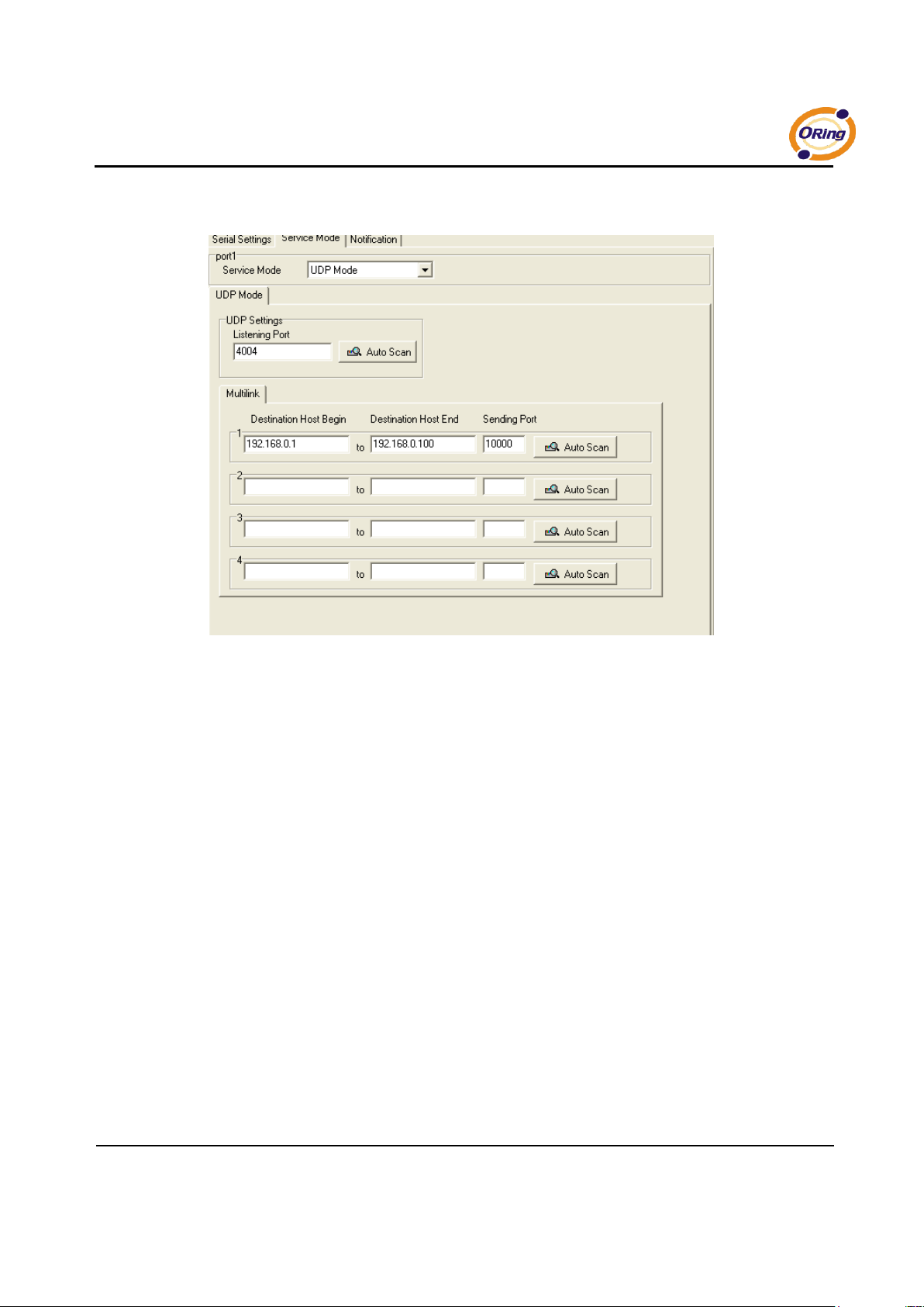
Service Mode – UDP Mode
Compared to TCP communication, UDP is faster and more efficient. In UDP
mode, you can Uni-cast or Multi-cast data from the serial device server to host
computers, and the serial device can also receive data from one or multiple
host
Page 36
IDS-141A_181A Series User’s Manual
ORing Industrial Networking Corp 32.
Figure 5-17 UDP mode
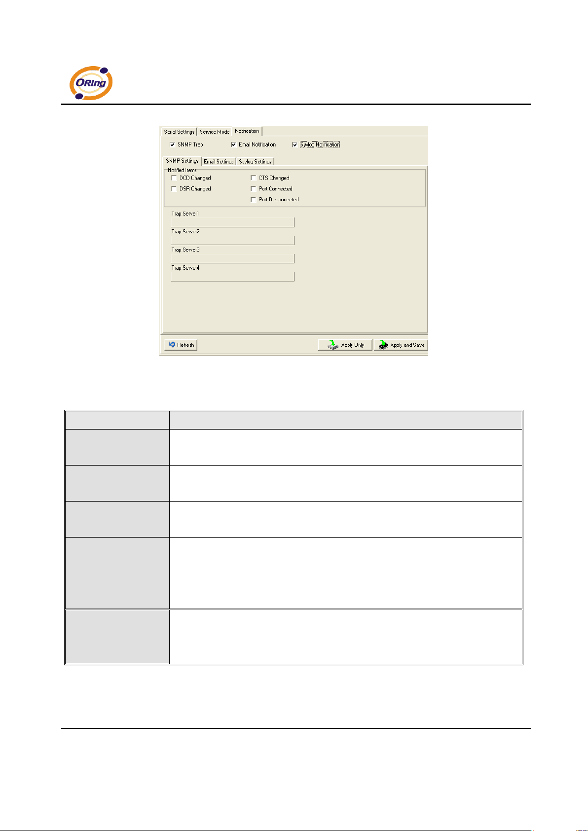
Notification
Specify the events that should be noticed. The events can be noticed by
E-mail, SNMP trap or system log.
Page 37
IDS-141A_181A Series User’s Manual
33 ORing Industrial Networking Corp.
Figure 5-18 Notification
The following table describes the labels in this screen.
Label
Description
DCD changed
When DCD (Data Carrier Detect) signal changes, it indicates that the modem
connection status has changed. Notification will be sent.
DSR changed
When DSR (Data Set Ready) signal changes, it indicates that the data communication
equipment is powered off. A Notification will be sent.
CTS changed
When CTS (Clear To Send) signal changes, it indicates that the transmission between
computer and DCE can proceed. A notification will be sent.
Port connected
In TCP Server Mode, when the device accepts an incoming TCP connection, this event
will be trigger. In TCP Client Mode, when the device has connected to the remote host,
this event will be trigger. In Virtual COM Mode, Virtual COM is ready to use. A
notification will be sent.
Port disconnected
In TCP Server/Client Mode, when the device lost the TCP link, this event will be trigger.
In Virtual COM Mode, When Virtual COM is not available, this event will be trigger. A
notification will be sent.
Table 5-11 Notification
Page 38
IDS-141A_181A Series User’s Manual
ORing Industrial Networking Corp 34.
5.2 Configuration by Web Browser
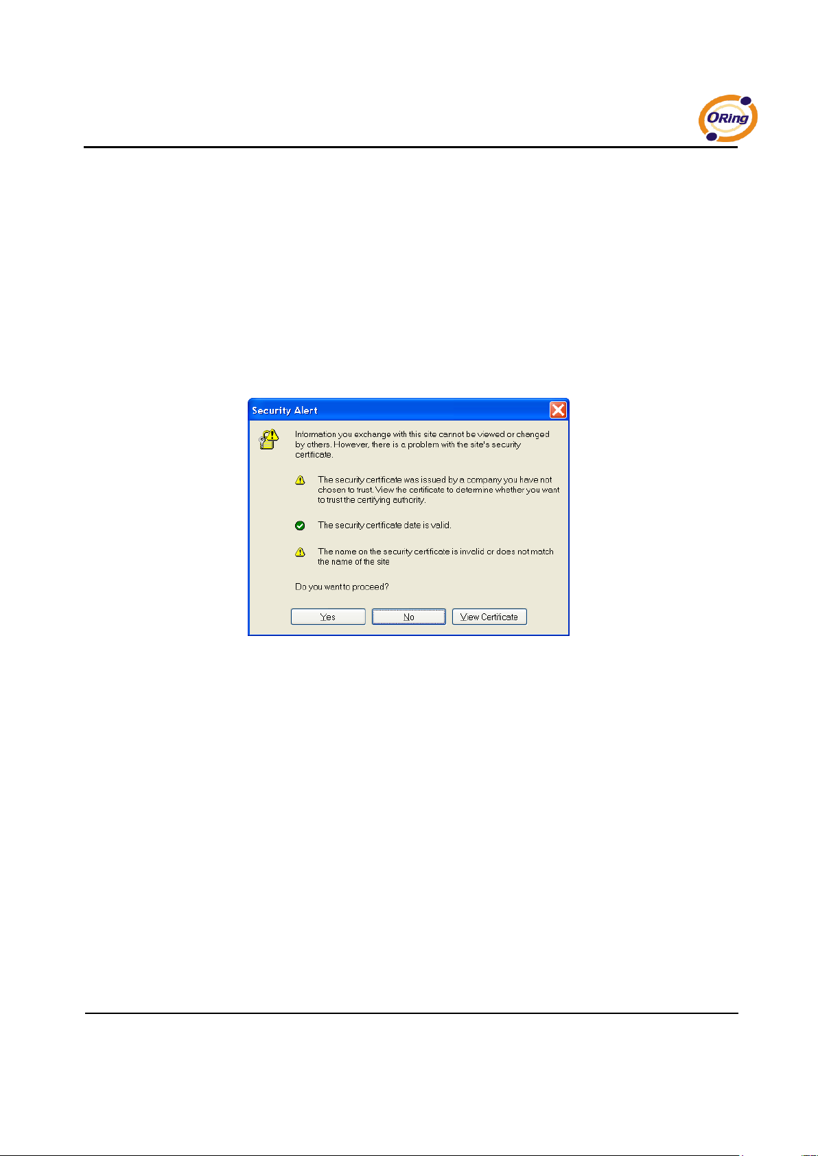
5.2.1 CONNECT TO THE WEB PAGE
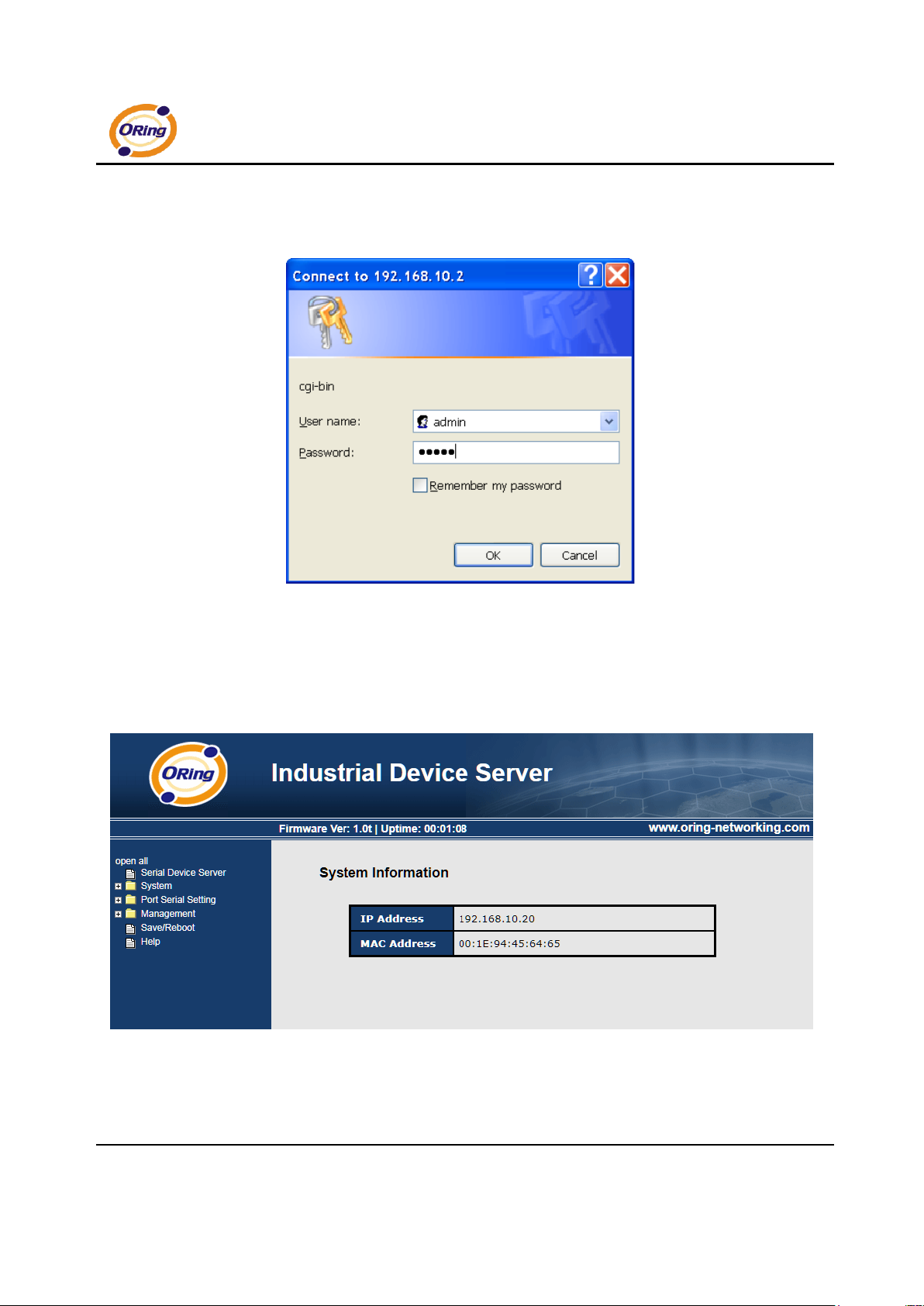
Step 1: Input the IP address of DS with “https://192.168.10.2” in the Address input box of
IE.
Step 2: Click “Yes” button on the dialog box.
Figure 5-19 Certificates
Page 39
IDS-141A_181A Series User’s Manual
35 ORing Industrial Networking Corp.
Step 3: Input the name and password, then click “OK”.
Figure 5-20 Certificates
*Only if password is set.
Step 4: The system information will be shown as below.
Figure 5-21 System information
Page 40
IDS-141A_181A Series User’s Manual
ORing Industrial Networking Corp 36.
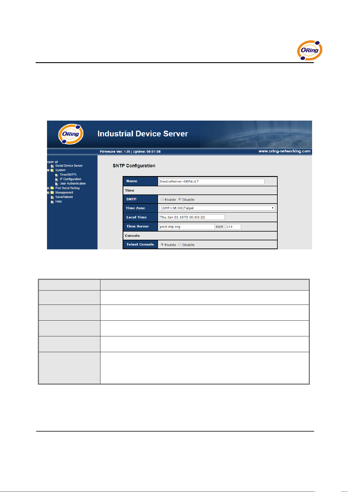
5.2.1.1 System
Time (SNTP)
Figure 5-22 Time (SNTP)
The following table describes the labels in this screen.
Label
Description
Name
You can set the name of DS.
SNTP
Enable the SNTP server.
Time zone
After you set the SNTP enable, select the time zone you located.
Time server
Input SNTP server domain name or IP address and Port.
Console
Telnet Console (SSH) is included for security reasons. In some cases, you may need
to disable this function to prevent unauthorized access from internet. The factory
default is enable.
Table 5-12 Time (SNTP)
Page 41
IDS-141A_181A Series User’s Manual
37 ORing Industrial Networking Corp.
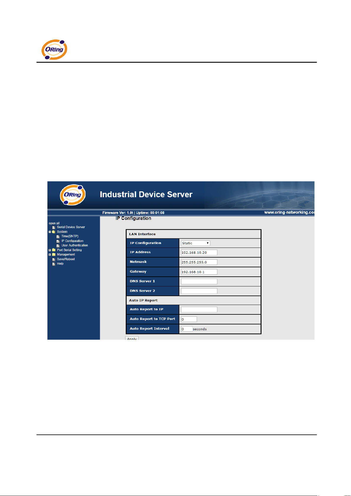
IP Configuration
You must assign a valid IP address for DS before attached in your network
environment. Your network administrator should provide you with the IP address
and related settings. The IP address must be unique and within the network
(otherwise, DS will not have a valid connection to the network). You can choose
from three possible “IP configuration” modes: Static, DHCP/BOOTP. The Factory
Default IP address is “192.168.10.2”
Figure 5-23 IP configuration
Page 42
IDS-141A_181A Series User’s Manual
ORing Industrial Networking Corp 38.
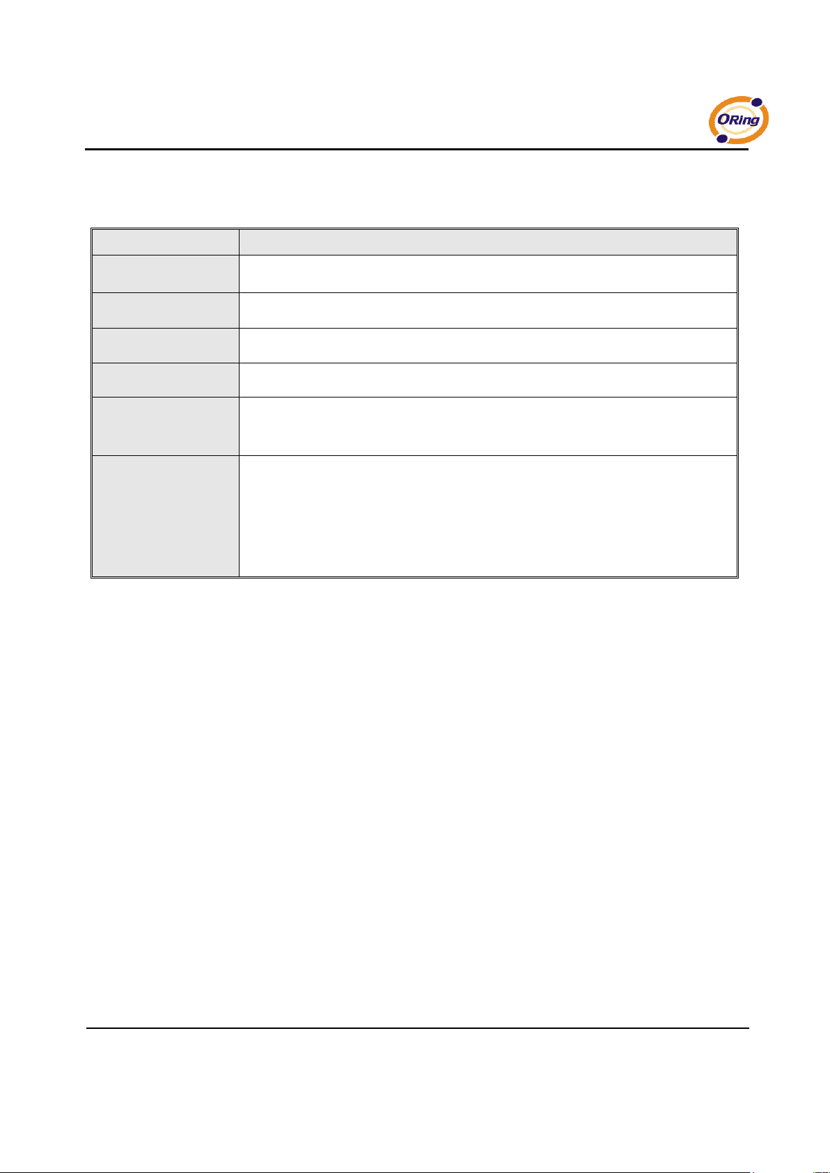
The following table describes the labels in this screen.
Label
Description
DHCP/BOOTP
Obtain the IP address automatically from DHCP server.
Static IP Address
Assigning an IP address manually.
Subnet Mask
Set the subnet mask to communicate on the network.
Gateway
Enter the IP address of the router in you network.
DNS Server
Enter the IP address of the DNS server to translate domain names into IP address.
Auto IP Report
The device server will report its status periodically. At DS-Tool->IP collection option
show the device server status. The report interval is 0 indicate disable this setting
(default). But you can set the other IP or Port.
Table 5-13 IP configuration
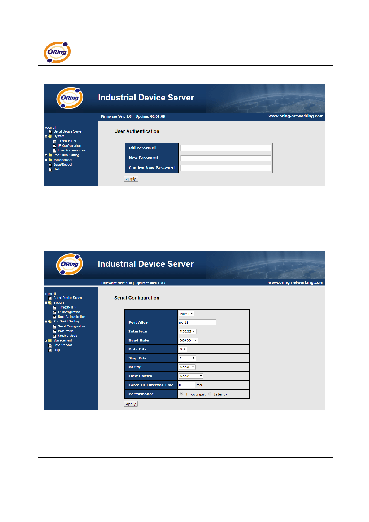
Authentication
You can set the password to prevent unauthorized access from network. Input the
“Old password” and “New password” to change the password. Factory default is
no password.
Page 43
IDS-141A_181A Series User’s Manual
39 ORing Industrial Networking Corp.
Figure 5-24 Authentication
5.2.1.2 Port serial setting
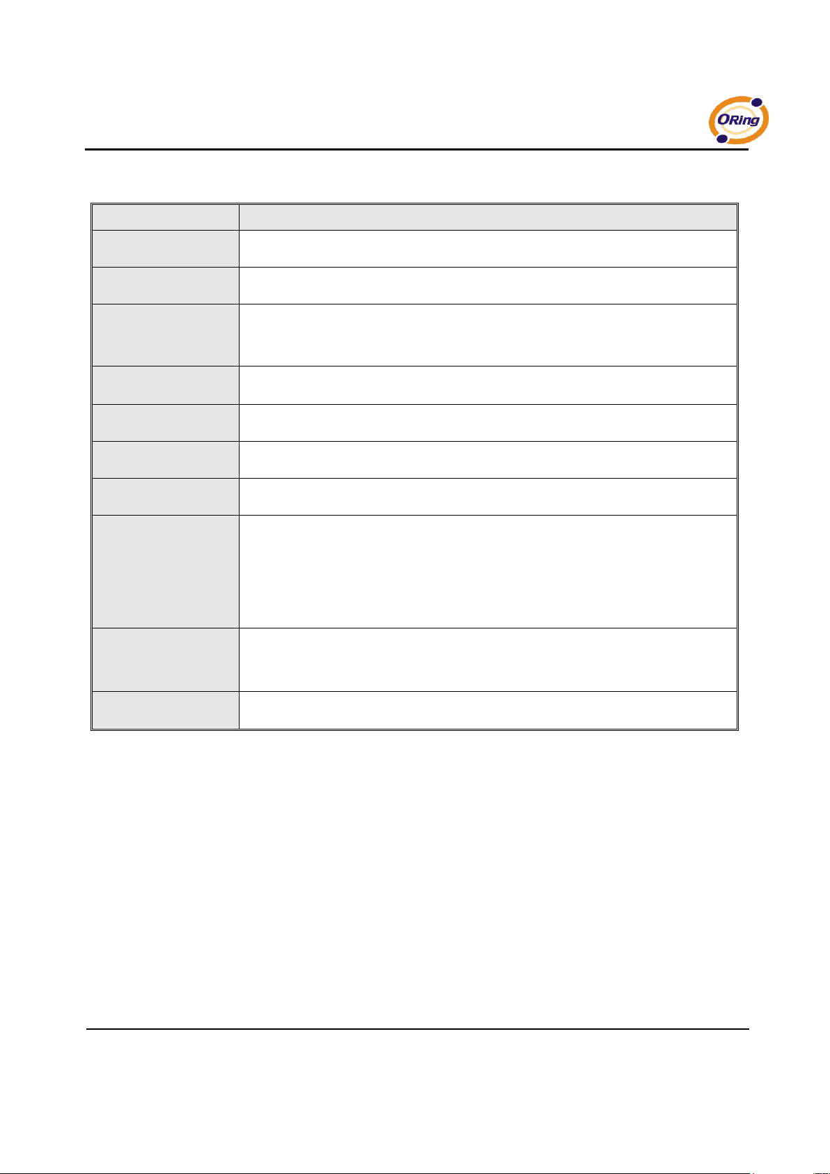
Serial configuration
Figure 5-25 Serial configuration
Page 44
IDS-141A_181A Series User’s Manual
ORing Industrial Networking Corp 40.
The following table describes the labels in this screen.
Label
Description
Port Alias
Remark the port to hint the connected device.
Interface
RS232
Baud rate
1200bps/2400bps/4800bps/9600bps/19200bps/ 38400bps/57600bps/115200bps
Data Bits
7, 8
Stop Bits
1, 2 (1.5)
Parity
No, Even, Odd, Mark, Space
Flow Control
No, XON/XOFF, RTS/CTS, DTR/DSR
Force TX Interval Time
Force TX interval time is to specify the timeout when no data has been transmitted.
When the timeout is reached or TX buffer is full (4K Bytes), the queued data will be sent.
0 means disable. Factory default value is 0.
Performance
Throughput: This mode optimized for highest transmission speed.
Latency: This mode optimized for shortest response time.
Apply
Activate settings on this page.
Table 5-14 Serial configuration
Page 45
IDS-141A_181A Series User’s Manual
41 ORing Industrial Networking Corp.
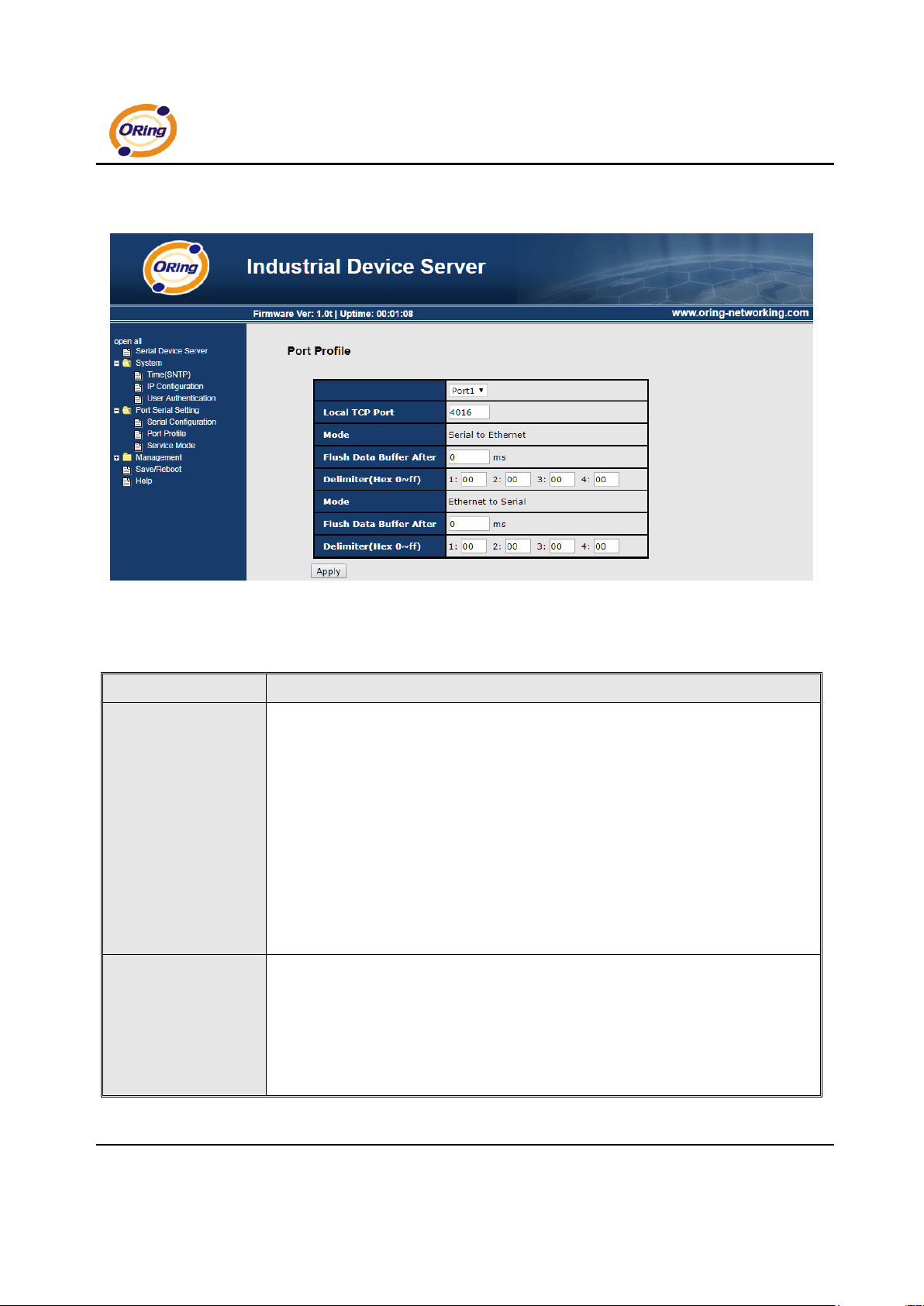
Port Profile
Figure 5-26 Port Profile
The following table describes the labels in this screen.
Label
Description
Serial to Ethernet
Flush Data Buffer After:
The received data will be queued in the buffer until all the delimiters are matched.
When the buffer is full (4K Bytes) or after "flush S2E data buffer" timeout, the data will
also be sent. You can set the time from 0 to 65535 seconds.
Delimiter:
You can define max. 4 delimiters (00~FF, Hex) for each way. The data will be hold until
the delimiters are received or the option “Flush Serial to Ethernet data buffer” times
out. 0 means disable. Factory default is 0
Ethernet to serial
Flush Data Buffer After:
The received data will be queued in the buffer until all the delimiters are matched.
When the buffer is full (4K Bytes) or after "flush E2S data buffer" timeout, the data will
also be sent. You can set the time from 0 to 65535 seconds.
Page 46
IDS-141A_181A Series User’s Manual
ORing Industrial Networking Corp 42.
Delimiter:
You can define max. 4 delimiters (00~FF, Hex) for each way. The data will be hold until
the delimiters are received or the option “Flush Ethernet to Serial data buffer” times
out. 0 means disable. Factory default is 0
Table 5-15 Port Profile
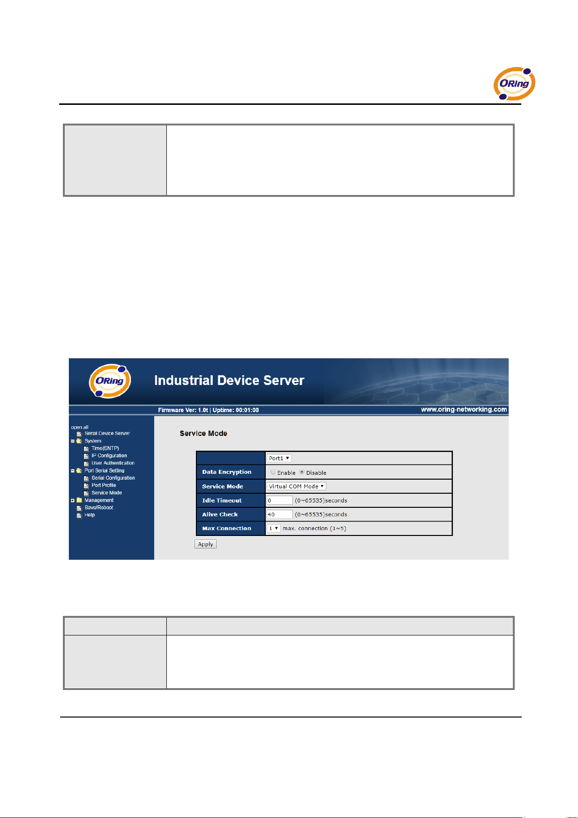
Service Mode – Virtual COM Mode
In Virtual COM Mode, the driver establishes a transparent connection between host
and serial device by mapping the Port of the serial server serial port to local COM
port on the host computer. Virtual COM Mode also supports up to 5 simultaneous
connections, so that multiple hosts can send or receive data by the same serial
device at the same time.
Figure 5-27 Virtual COM mode
The following table describes the labels in this screen.
Label
Description
Idle Timeout
When serial port stops data transmission for a defined period of time (Idle Timeout), the
connection will be closed and the port will be freed and try to connect with other hosts.
0 indicate disable this function. Factory default value is 0. If Multilink is configured,
Page 47
IDS-141A_181A Series User’s Manual
43 ORing Industrial Networking Corp.
only the first host connection is effective for this setting.
Alive Check
The serial device will send TCP alive-check package in each defined time interval (Alive
Check) to remote host to check the TCP connection. If the TCP connection is not
alive, the connection will be closed and the port will be freed. 0 indicate disable this
function. Factory default is 0.
Max Connection
The number of Max connection can support simultaneous connections are 5, default
values is 1.
Table 5-16 Virtual COM mode
*Not allowed to mapping Virtual COM from web
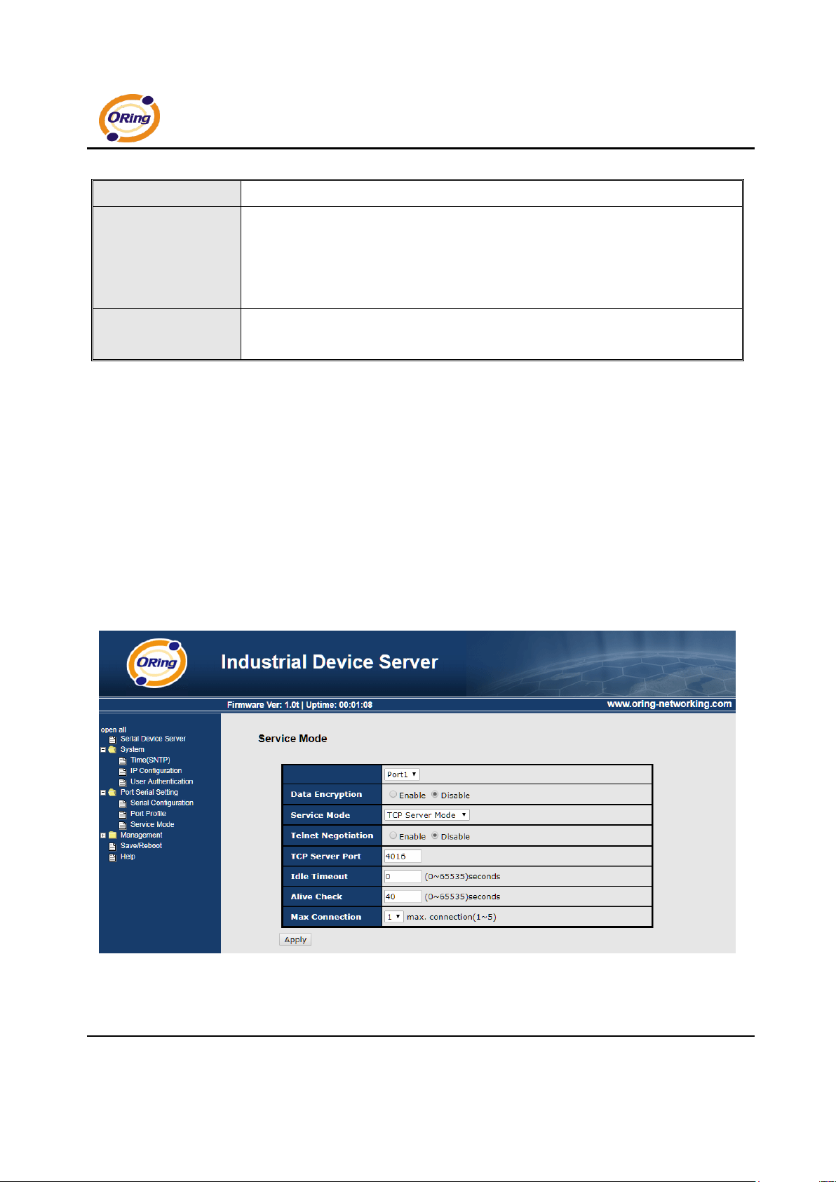
Service Mode – TCP Server Mode
In TCP Server Mode, DS is configured with a unique Port combination on a TCP/IP
network. In this case, DS waits passively to be contacted by the device. After the
device establishes a connection with the serial device, it can then proceed with data
transmission. TCP Server mode also supports up to 5 simultaneous connections,
so that multiple device can receive data from the same serial device at the same
time.
Figure 5-28 TCP Server Mode
Page 48
IDS-141A_181A Series User’s Manual
ORing Industrial Networking Corp 44.
The following table describes the labels in this screen.
Label
Description
TCP Server Port
Set the port number for data transmission.
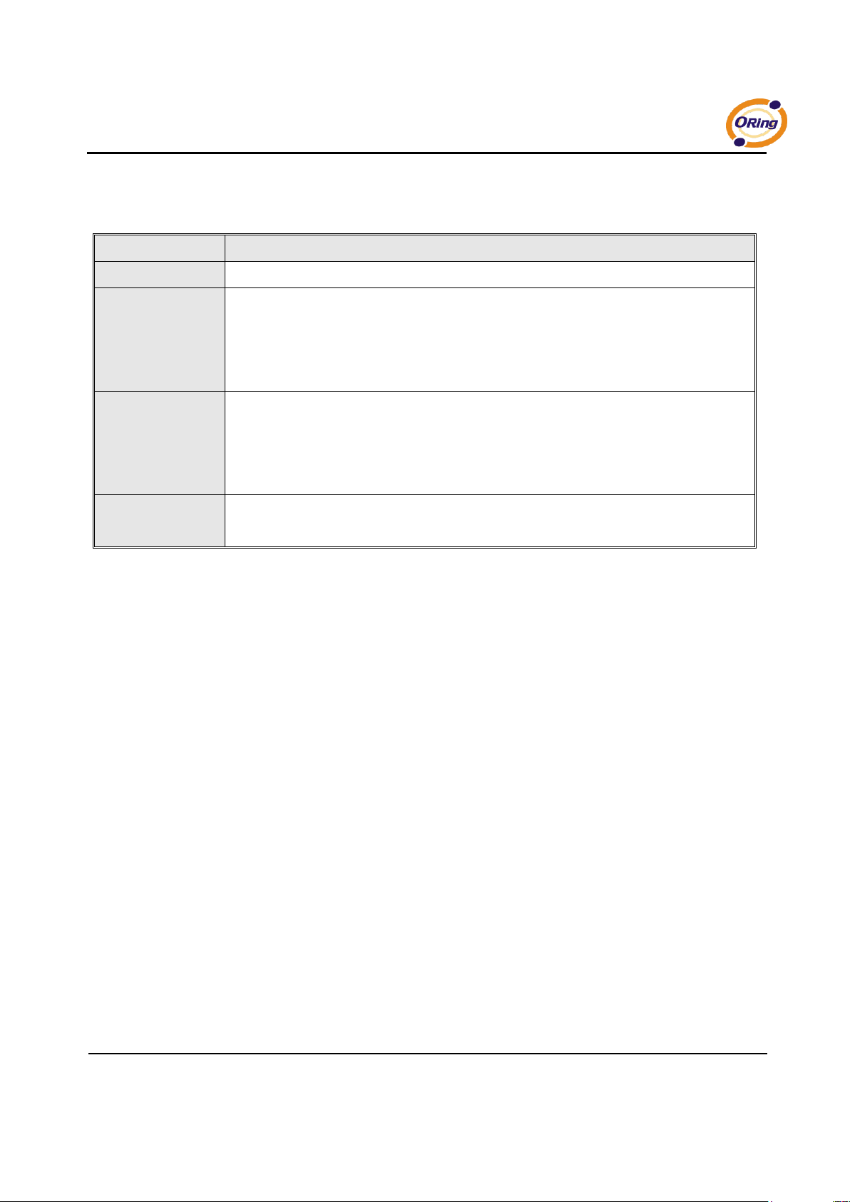
Idle Timeout
When serial port stops data transmission for a defined period of time (Idle Timeout), the
connection will be closed and the port will be freed and try to connect with other hosts. 0
indicate disable this function. Factory default value is 0. If Multilink is configured, only
the first host connection is effective for this setting.
Alive Check
The serial device will send TCP alive-check package in each defined time interval (Alive
Check) to remote host to check the TCP connection. If the TCP connection is not alive,
the connection will be closed and the port will be freed. 0 indicate disable this function.
Factory default is 0.
Max Connection
The number of Max connection can support simultaneous connections are 5, default values
is 1.
Table 5-17 TCP server mode
Page 49
IDS-141A_181A Series User’s Manual
45 ORing Industrial Networking Corp.
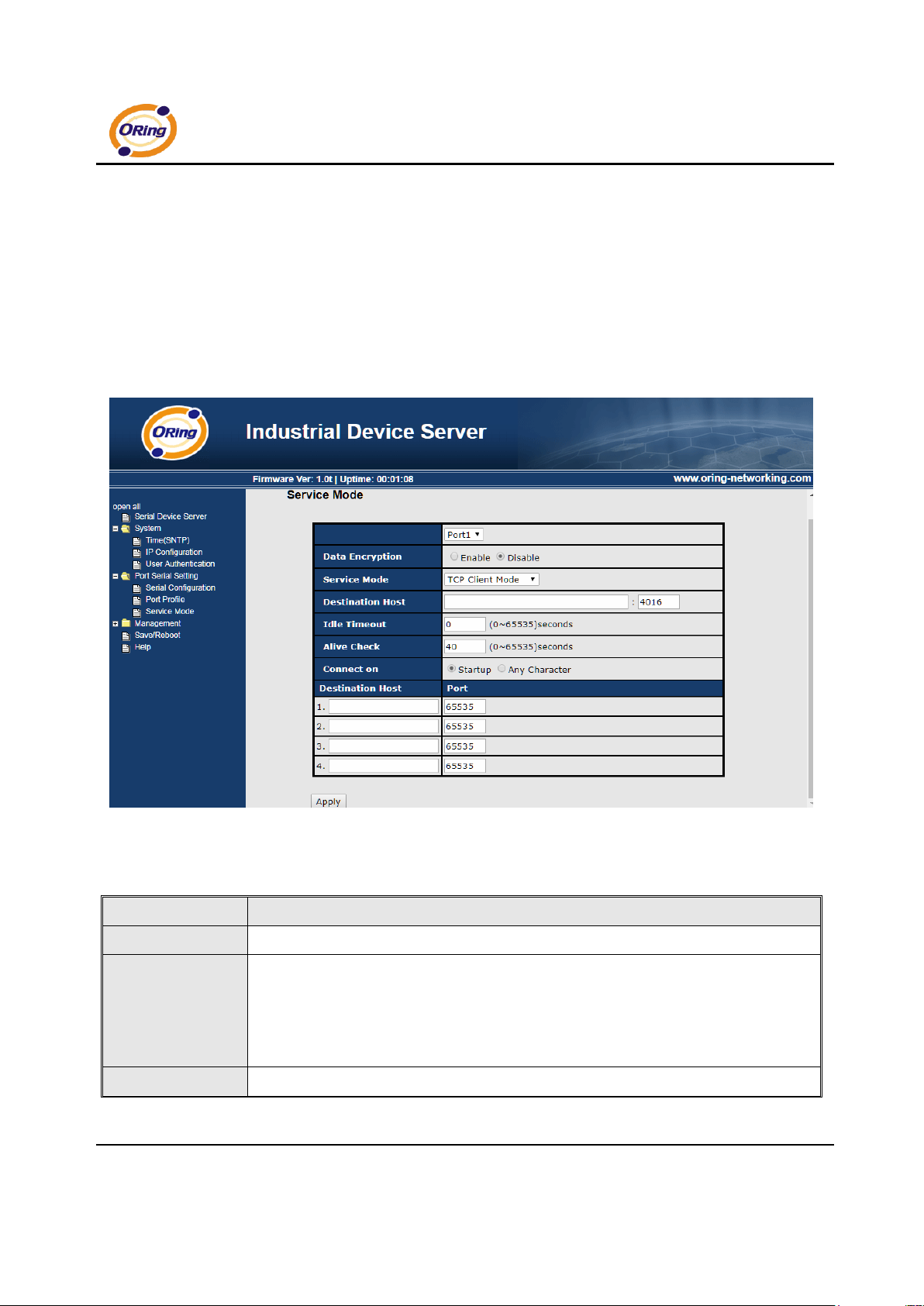
Service Mode – TCP Client Mode
In TCP Client Mode, device can establish a TCP connection with server by the
method you set (Startup or any character). After the data has been
transferred, device can disconnect automatically from the server by using the
TCP alive check time or Idle timeout settings.
Figure 5-29 TCP client mode
The following table describes the labels in this screen.
Label
Description
Destination Host
Set the IP address of host and the port number of data port. .
Idle Timeout
When serial port stops data transmission for a defined period of time (Idle Timeout), the
connection will be closed and the port will be freed and try to connect with other hosts. 0
indicate disable this function. Factory default value is 0. If Multilink is configured, only
the first host connection is effective for this setting.
Alive Check
The serial device will send TCP alive-check package in each defined time interval (Alive
Page 50
IDS-141A_181A Series User’s Manual
ORing Industrial Networking Corp 46.
Check) to remote host to check the TCP connection. If the TCP connection is not alive,
the connection will be closed and the port will be freed. 0 indicate disable this function.
Factory default is 0.
Connect on Startup
The TCP Client will build TCP connection once the connected serial device is started.
Connect on Any
Character
The TCP Client will build TCP connection once the connected serial device starts to send
data.
Table 5-18 TCP client mode
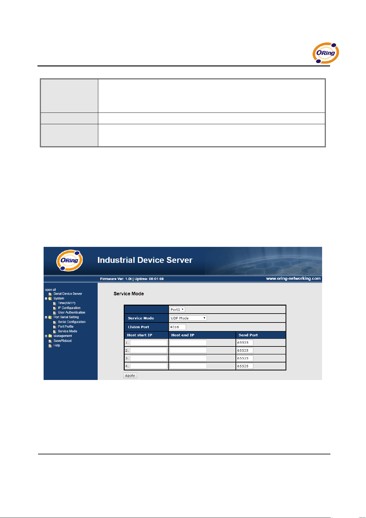
Service Mode – UDP Client Mode
Compared to TCP communication, UDP is faster and more efficient. In UDP
mode, you can Uni-cast or Multi-cast data from the serial device server to host
computers, and the serial device can also receive data from one or multiple
host
Figure 5-30 UDP client mode
Page 51
IDS-141A_181A Series User’s Manual
47 ORing Industrial Networking Corp.
5.2.1.3 Management
Access IP Control
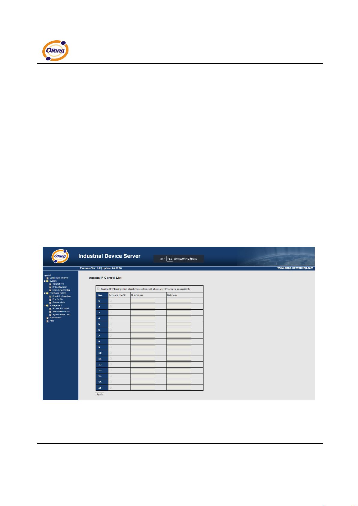
Access IP Control Settings allow you to add or block the remote host IP
addresses to prevent unauthorized access. If host’s IP address is in the
accessible IP table, then the host will be allowed to access the DS. You can
choose one of the following cases by setting the parameter.
1. Only one host with a special IP address can access the device server, “IP
address /255.255.255.255” (e.g., “192.168.0.1/255.255.255.255”).
2. Hosts on a specific subnet can access the device server. “IP
address/255.255.255.0” (e.g., “192.168.0.2/255.255.255.0”)
3. Any host can access the device server. Disable this function by
un-checking the “Enable IP Filter” checkbox
Figure 5-31 Access IP
Page 52
IDS-141A_181A Series User’s Manual
ORing Industrial Networking Corp 48.
SMTP/SNMP Conf
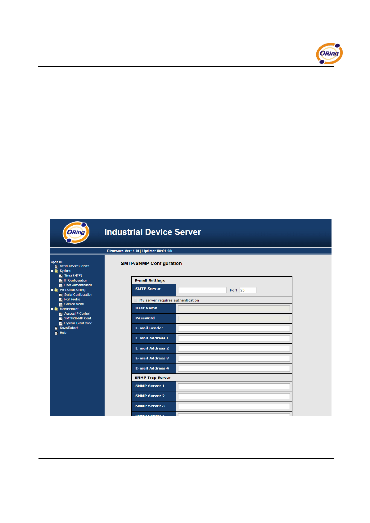
Email Server configuration includes the mail server’s IP address or domain. If
the authentication is required, specify your name and password. There are 4
Email addresses that you can specify to receive the notification.
SNMP Server configuration includes the SNMP Trap Server IP address,
Community, Location and Contact. There are 4 SNMP addresses you can
specify to receive the notification.
SysLog server configuration includes the server IP and server Port. This option
need to use with DS-Tool.
Figure 5-32 SMTP / SNMP conf
Page 53
IDS-141A_181A Series User’s Manual
49 ORing Industrial Networking Corp.
System Event Conf.
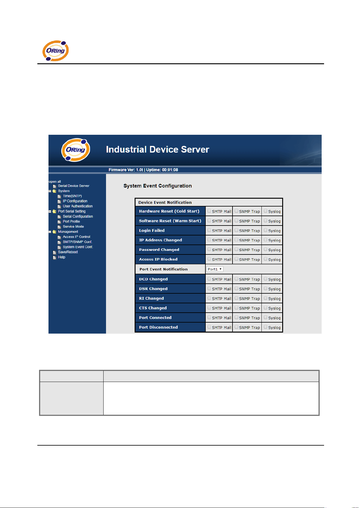
Specify the events that should be notified to the administrator. The events can be
alarmed by E-mail, SNMP trap, or system log.
Figure 5-33 SMTP / SNMP conf
The following table describes the labels in this screen.
Label
Description
Hardware Reset (Cold
Start)
This refers to starting the system from power off (contrast this with warm start). When
performing a cold start, DS will automatically issue an Auto warning message by
sending E-mail, log information or an SNMP trap after booting.
Page 54
IDS-141A_181A Series User’s Manual
ORing Industrial Networking Corp 50.
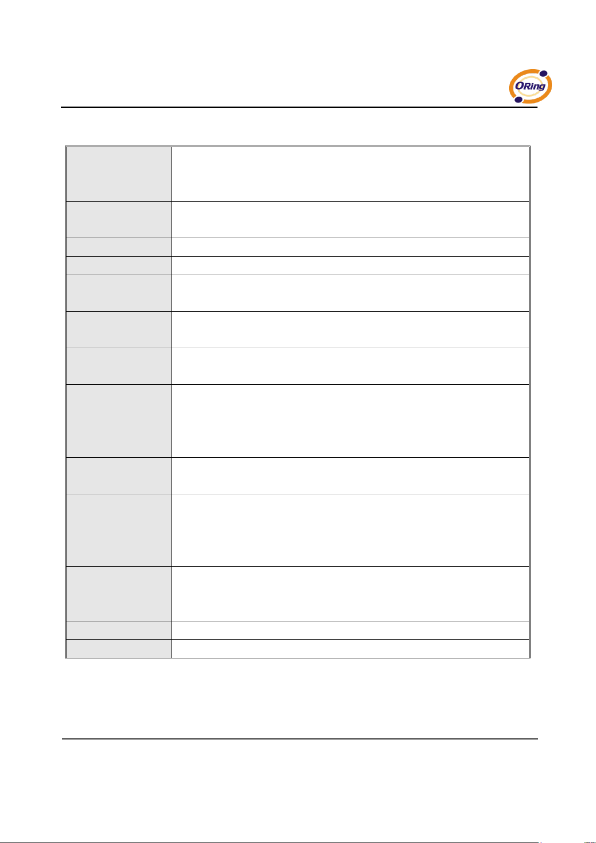
Software Reset (Warm
Start)
This refers to restart the computer without turning the power off. When performing a
warm start, DS will automatically send an E-mail, log information or SNMP trap after
reboot.
Login Failed
When an unauthorized access from the Console or Web interface, a notification will be
sent.
IP Address Changed
When IP address of device changed, a notification will be sent.
Password Changed
When password of device changed, a notification will be sent.
Access IP Blocked
When the host accesses the device with blocked IP addresses, a notification will be
sent.
Redundant Power
Change
When status of power changed, a notification will be sent.
Redundant Ethernet
Change
When status of Ethernet port changed, a notification will be sent.
DCD changed
When DCD (Data Carrier Detect) signal changes, it indicates that the modem
connection status has been changed. A Notification will be sent.
DSR changed
When DSR (Data Set Ready) signal changes, it indicates that the data communication
equipment is powered off. A Notification will be sent.
CTS changed
When CTS (Clear To Send) signal changes, it indicates that the transmission between
computer and DCE can proceed. A notification will be sent.
Port connected
In TCP Server Mode, when the device accepts an incoming TCP connection, this event
will be trigger. In TCP Client Mode, when the device has connected to the remote host,
this event will be trigger. In Virtual COM Mode, Virtual COM is ready to use. A
notification will be sent.
Port disconnected
In TCP Server/Client Mode, when the device lost the TCP link, this event will be trigger.
In Virtual COM Mode, When Virtual COM is not available, this event will be trigger. A
notification will be sent.
Power 1 Fault
When Power 1 Fault, a notification will be sent and the Fault LED will be lighted.
Power 2 Fault
When Power 2 Fault, a notification will be sent and Fault LED will be lighted.
Page 55
IDS-141A_181A Series User’s Manual
51 ORing Industrial Networking Corp.
Eth link down
When Eth link down, a notification will be sent and Fault LED will be lighted.
Table 5-19 System event conf
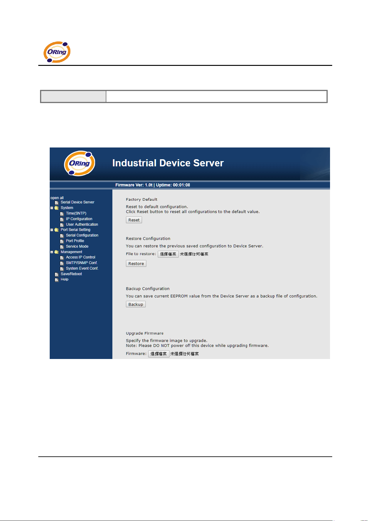
5.2.1.4 Save/Reboot
Figure 5-34 Save / Reboot
Page 56
IDS-141A_181A Series User’s Manual
ORing Industrial Networking Corp 52.
The following table describes the labels in this screen.
Label
Description
Factory Default
Load default configuration except settings of Network. If you want load all factory default,
you should press “Reset” button about the five seconds on the device (Hardware restore).
Restore
Configuration
Restore the previous exported configuration.
Backup
Configuration
Export the current configuration to a file.
Upgrade Firmware
Upgrade to a new firmware with specified file.
Reboot Device
Reboot the device server (warm start).
Table 5-20 Save / Reboot
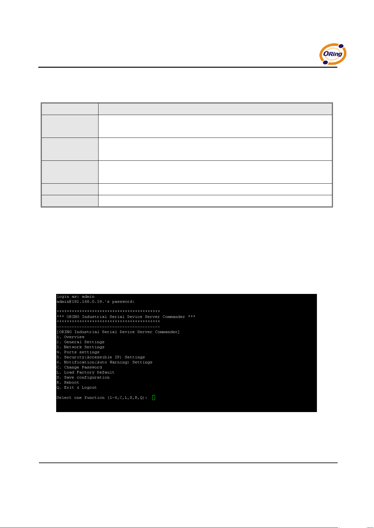
5.3 Configuration by SSH Console
5.3.1 Connect to DS
You can use SSH Tool (e.g., PUTTY) to access SSH console of DS. The SSH console
interface is shown below.
Figure 5-35 SSH
Page 57
IDS-141A_181A Series User’s Manual
53 ORing Industrial Networking Corp.
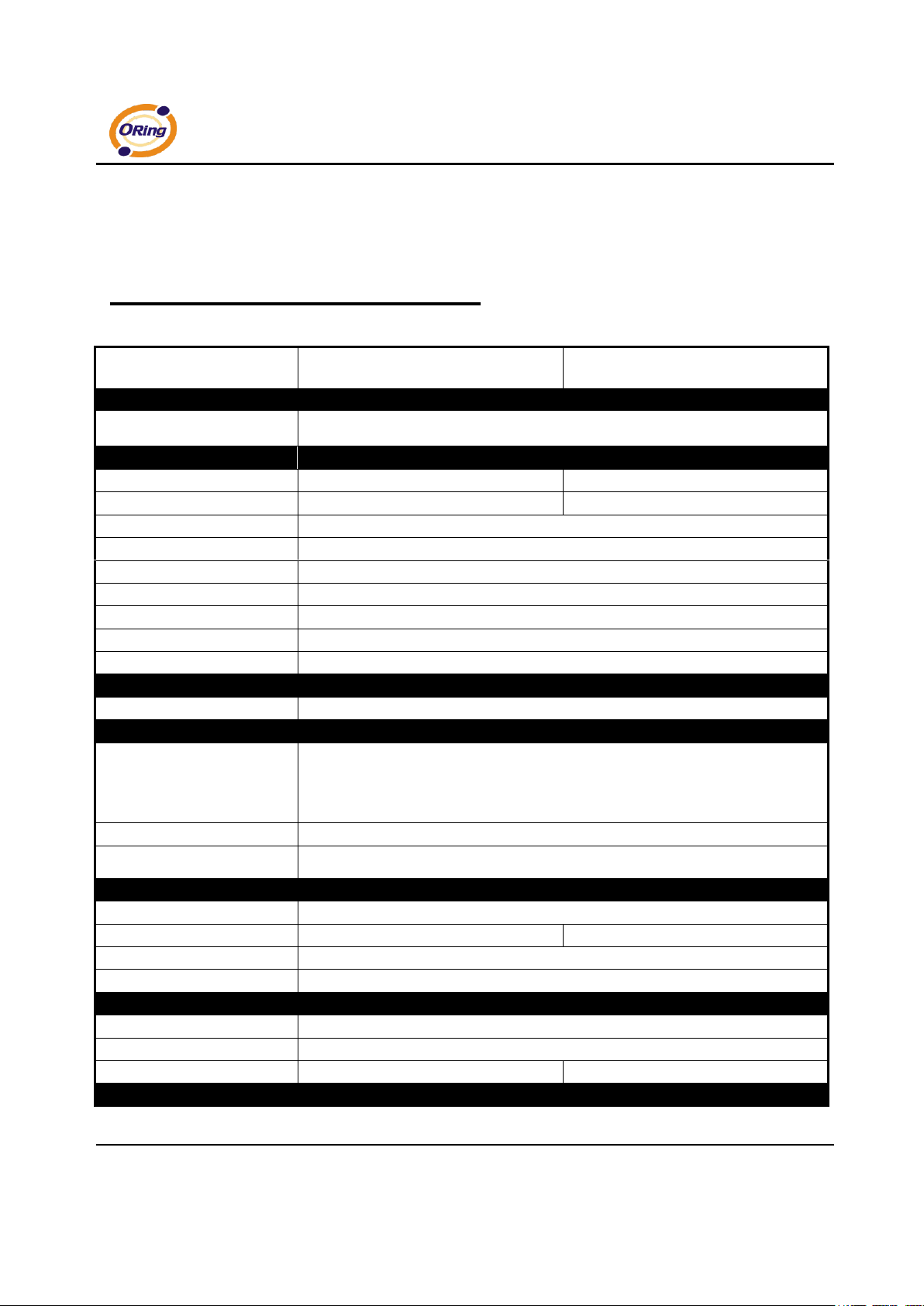
Technical Specifications
ORing Device Server Model
IDS-181A
IDS-141A
Feature
10/100 Base-T(X) Ports in RJ45
Auto MDI/MDIX
1
Serial Ports
RS-232 Serial port number 8 4
Connector
DB62 Female (provide DB62 to 8 ports DB9 cable)
DB62 Female (provide DB62 to 4 ports DB9 cable)
Operation Mode
RS-232
Serial Baud Rate
1200 bps to 115.2 Kbps
Data Bits
7, 8
Parity
odd, even, none, mark, space
Stop Bits
1, 1.5, 2
RS-232
TxD, RxD, RTS, CTS, DTR, DSR, DCD, GND
Flow Control
XON/XOFF, RTS/CTS, DTR/DSR
Network Features
Network Protocols
ICMP, IP, TCP, UDP, DHCP, BOOTP, SSH, DNS, SNMP V1/V2c, HTTPS, SMTP
LED indicators
Power indicator
PWR 1(2) / Ready:
Red On: Power is on and booting up.
Red Blinking: Indicates an IP conflict, or DHCP or BOOTP server did not respond properly.
Green On: Power is on and functioning Normally.
Green Blinking: Located by Administrator.
10/100TX RJ45 port indicator
Green for port Link/Act. Amber for port Link/Act at 100Mbps.
Serial TX / RX LEDs:
Red: Serial port is receiving data
Green: Serial port is transmitting data
Power
Redundant Input power
Dual DC inputs. 12-48VDC on 6-pin terminal block and power jack
Power consumption (Typ.)
4.5 Watts
3.7 Watts
Overload current protection
Present
Reverse polarity protection
Present on terminal block
Physical Characteristic
Enclosure
IP-30
Dimension (W x D x H)
94.9 x 23 x 144.3 (mm)
Weight (g)
358 g
355 g
Environmental
Page 58
IDS-141A_181A Series User’s Manual
ORing Industrial Networking Corp 54.
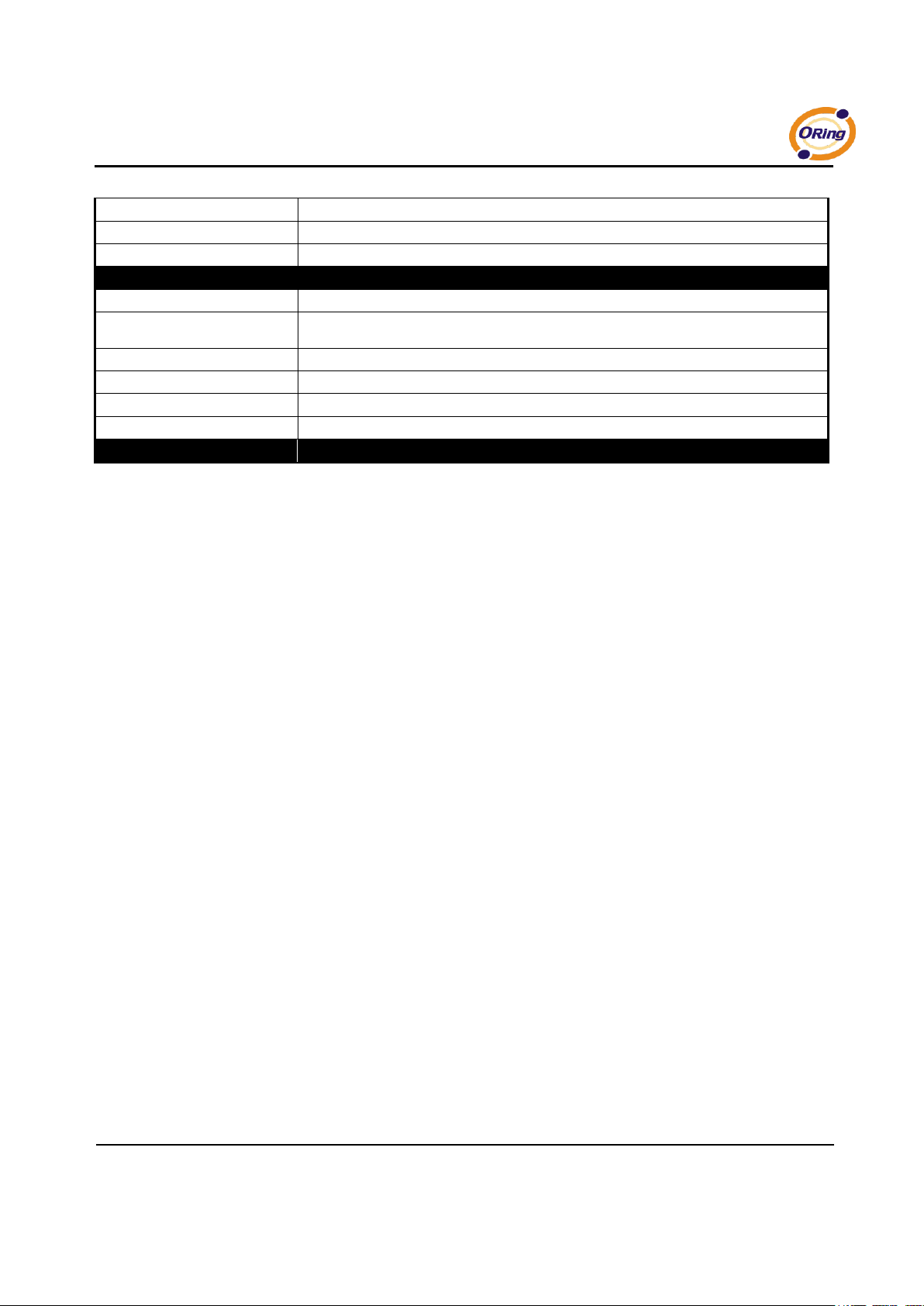
Storage Temperature
-40 to 85oC (-40 to 185oF)
Operating Temperature
-10 to 70oC (14 to 140oF)
Operating Humidity
5% to 95% Non-condensing
Regulatory approvals
EMI
FCC Part 15, CISPR (EN55022) class A
EMS
EN61000-4-2 (ESD), EN61000-4-3 (RS), EN61000-4-4 (EFT), EN61000-4-5 (Surge), EN61000-4-6 (CS),
EN61000-4-8, EN61000-4-11
Shock
IEC60068-2-27
Free Fall
IEC60068-2-32
Vibration
IEC60068-2-6
Safety
EN60950-1
Warranty
5 years
 Loading...