

Page 1
IAR-630-C
User Manual
Version 1.0
June, 2016
Page 2

Contents
Hardware Overview ....................................................................................... 1
1. Interface Description .......................................................................................................... 1
2. USB Connecter Pinout ....................................................................................................... 2
3. LED Description .................................................................................................................. 2
Management Interface .................................................................................. 3
1. Device Default Setting: .................................................................................................... 3
2. Over View ............................................................................................................................. 3
2.1 System Info .......................................................................................................................... 3
2.2 LAN Info .............................................................................................................................. 4
2.3 Wireless Info ........................................................................................................................ 4
2.4 DHCP List ............................................................................................................................ 4
3. Basic Setting ........................................................................................................................ 5
3.1 System Info Setting .............................................................................................................. 5
3.2 WAN ..................................................................................................................................... 5
3.3 LAN ..................................................................................................................................... 6
4. Wireless Setting .................................................................................................................. 8
4.1 AP Mode ............................................................................................................................... 8
4.2 Wireless Option .................................................................................................................. 10
5. Firewall settings: ............................................................................................................... 10
5.1 Firewall .............................................................................................................................. 10
5.2 Port Forwards ..................................................................................................................... 11
5.2 IP Forwards ........................................................................................................................ 12
5.3 MAC Filters ....................................................................................................................... 14
5.2 UPNP ................................................................................................................................. 15
6. System Tools: .................................................................................................................... 15
6.1Time Setting ........................................................................................................................ 15
6.2 SNMP ................................................................................................................................. 16
6.3 System Log ......................................................................................................................... 17
6.1 Ping .................................................................................................................................... 17
6.3 Firmware Upgrade.............................................................................................................. 18
6.4 Backup/Restore .................................................................................................................. 19
6.4 Change User/Password ....................................................................................................... 19
6.4 Logout ................................................................................................................................ 20
7. Compliance ........................................................................................................................ 21
Page 3
WLAN User Manual
1 ORing Industrial Networking Corp.
Hardware Overview
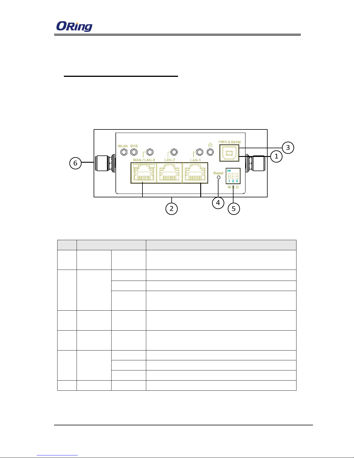
1. Interface Description
Item Port Description
1 PWR PWR &
Serial
15V(12~24V) DC Power Input
2 Ethernet LAN-1
10/100Base-T(X),RJ45
LAN-2
10/100Base-T(X),RJ45
WAN/LAN-
3
10/100/1000Base-T(X), RJ45
3 Console PWR &
Serial
RS232,115200,8,1, None
4
Reset Reset
Press reset button 5 seconds , then the device will restore
default configure
5 DIP- Switch W ON:WAN OFF: LAN
R ON: RF Enable OFF: RF Disable
D ON: DHCP Enable OFF: DHCP Disable
6 ANT ANT SMA, Female
Page 4
WLAN 模块使用手册
ORing Industrial Networking Corp. 2
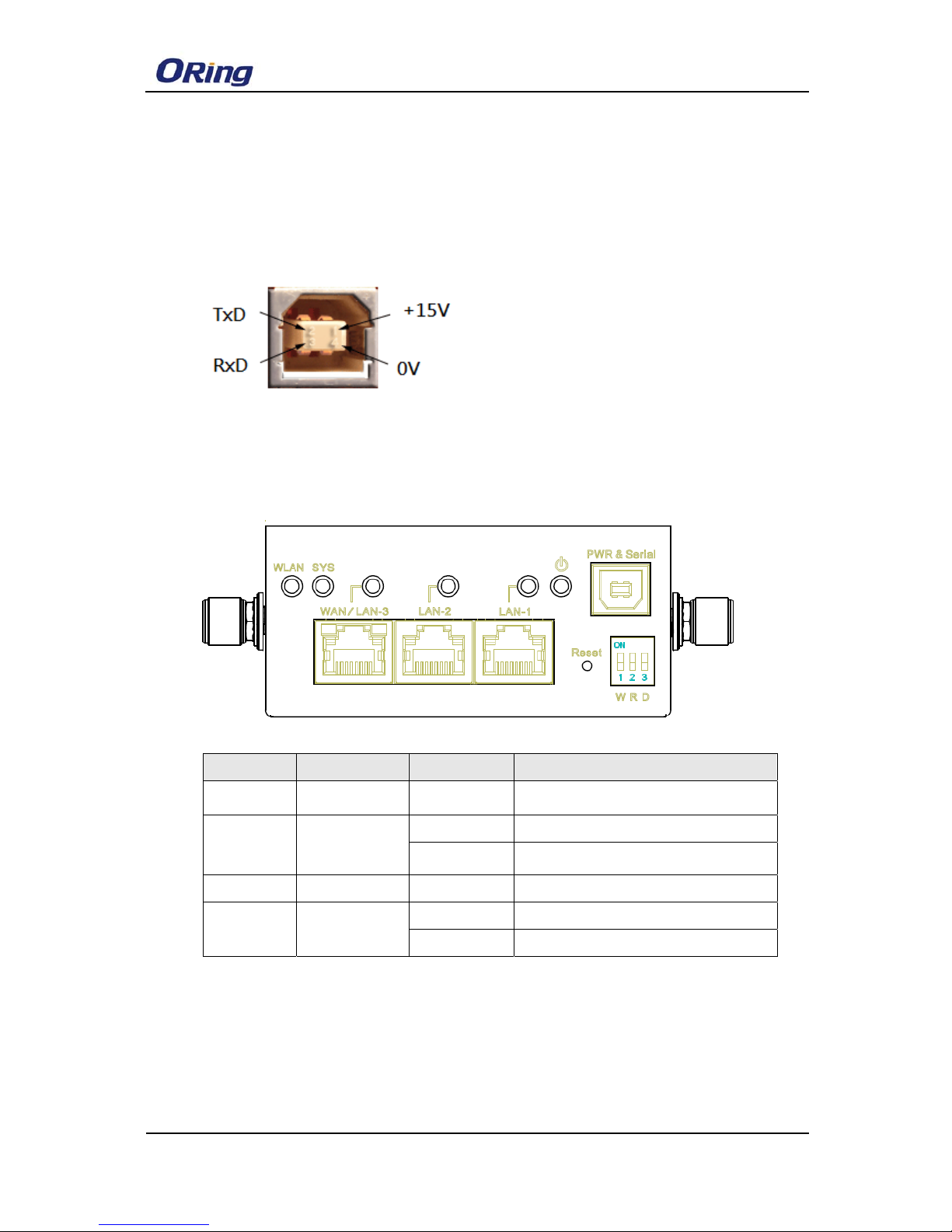
2. USB Connecter Pinout
Pin1: +15V
Pin2: UART_TxD
Pin3: UART_RxD
Pin4: 0V
3. LED Description
LED Color Status Description
PWR
Green
ON DC power is active
WLAN
Green
ON WLAN is active
Blinking
Data is being transmitted
SYS Green ON System startup is complete
LAN
Green
ON LAN port link is active
Blinking Data is being transmitted
Page 5
WLAN模块使用手册
3 ORing Industrial Networking Corp.
Management Interface
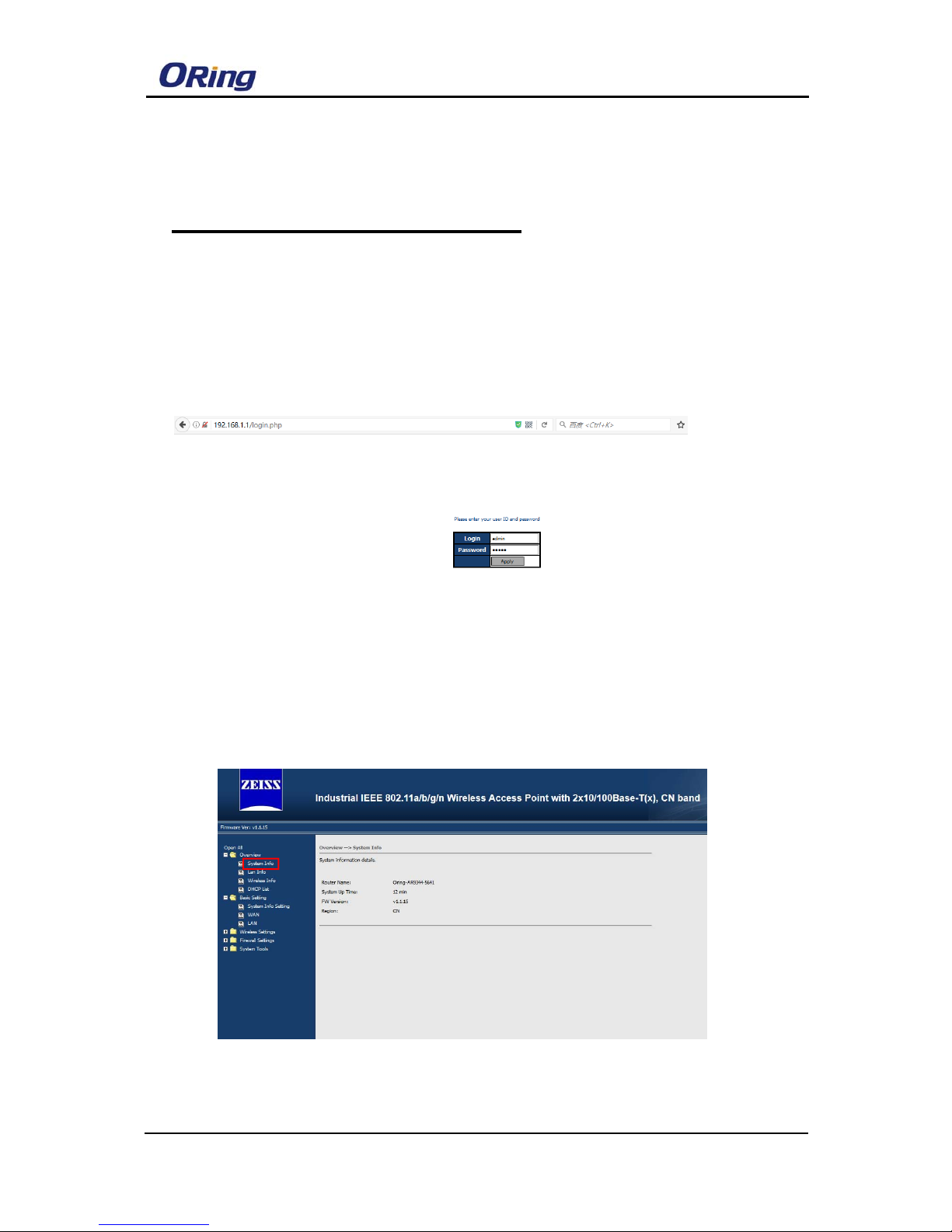
1. Device Default Setting:
IP Addesss:192168.1.1/255.255.255.0
Username: admin
Password: admin
2. Over View
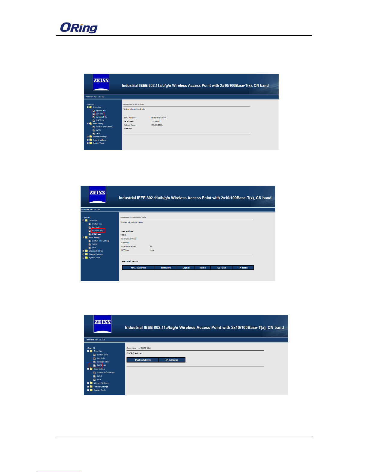
2.1 System Info
This Page will show the System Information in detail
Page 6
WLAN 模块使用手册
ORing Industrial Networking Corp. 4
2.2 LAN Info
This Page will show the LAN Information in detail.
2.3 Wireless Info
This Page will show the wireless Information in detail.
2.4 DHCP List
This Page will show the wireless DHCP client list IP address and Mac address
Page 7
WLAN模块使用手册
5 ORing Industrial Networking Corp.
3. Basic Setting
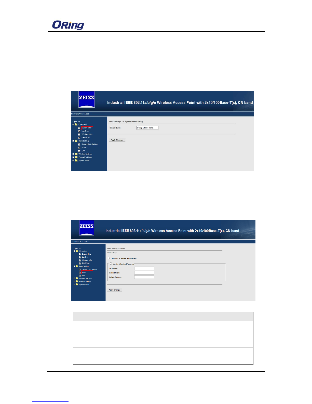
3.1 System Info Setting
You can change the device name and click “Apply Change” button to save
configuration.
3.2 WAN
System provides dip switch to easily configure LAN-3 Ethernet Port from LAN to
WAN mode in order to connect to outside network, you can set the WAN IP by
DHCP or Static IP mode.
Label Description
Obtain an IP
address
automatically
Select this option if you would like to obtain an IP address
automatically assigned by DHCP server in your network
Use the
following IP
Select this option if you are manually assigning an IP address,
subnet and Gateway
Page 8
WLAN 模块使用手册
ORing Industrial Networking Corp. 6
address
Note: 1. The device default LAN-3 Port is LAN mode, WAN mode is
disable. You must first set the LAN port as WAN mode by Dip
Switch “W”
.
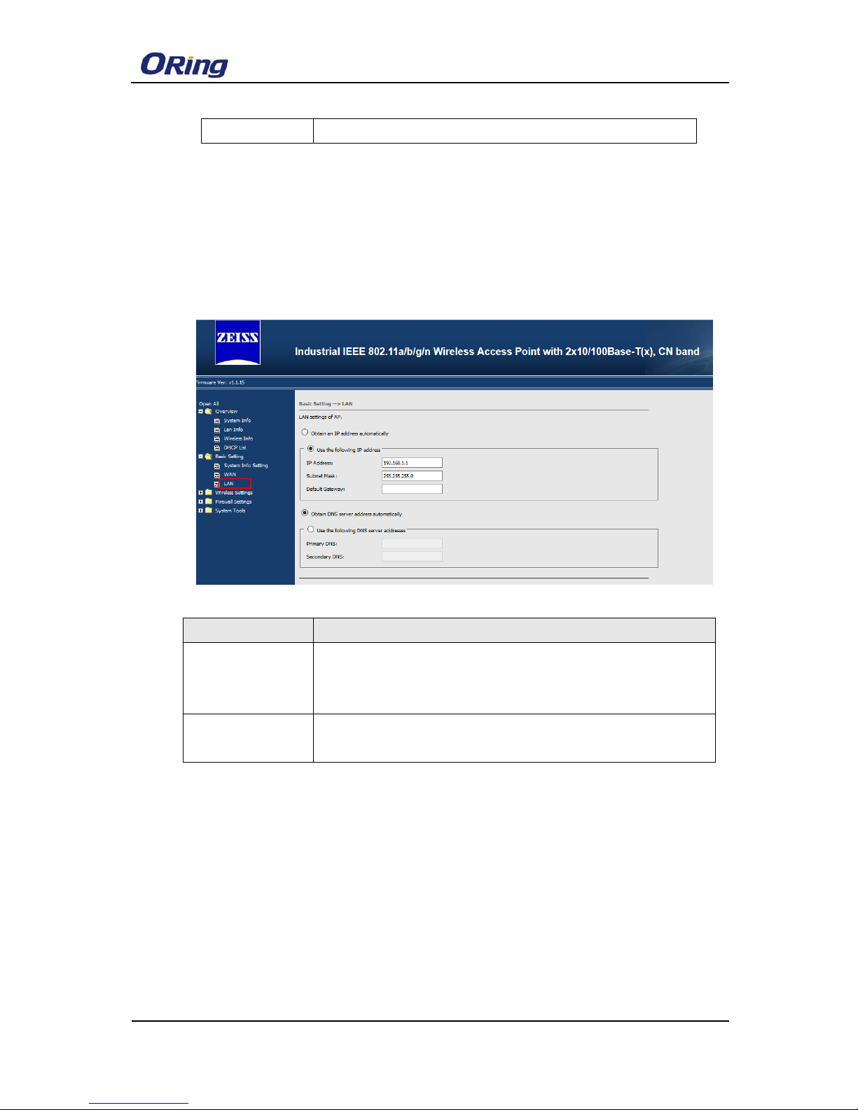
3.3 LAN
Label Description
Obtain an IP
address
automatically
Select this option if you would like to obtain an IP address
automatically assigned by DHCP server in your network
Use the following IP
address
Select this option if you are manually assigning an IP address.
Page 9
WLAN模块使用手册
7 ORing Industrial Networking Corp.
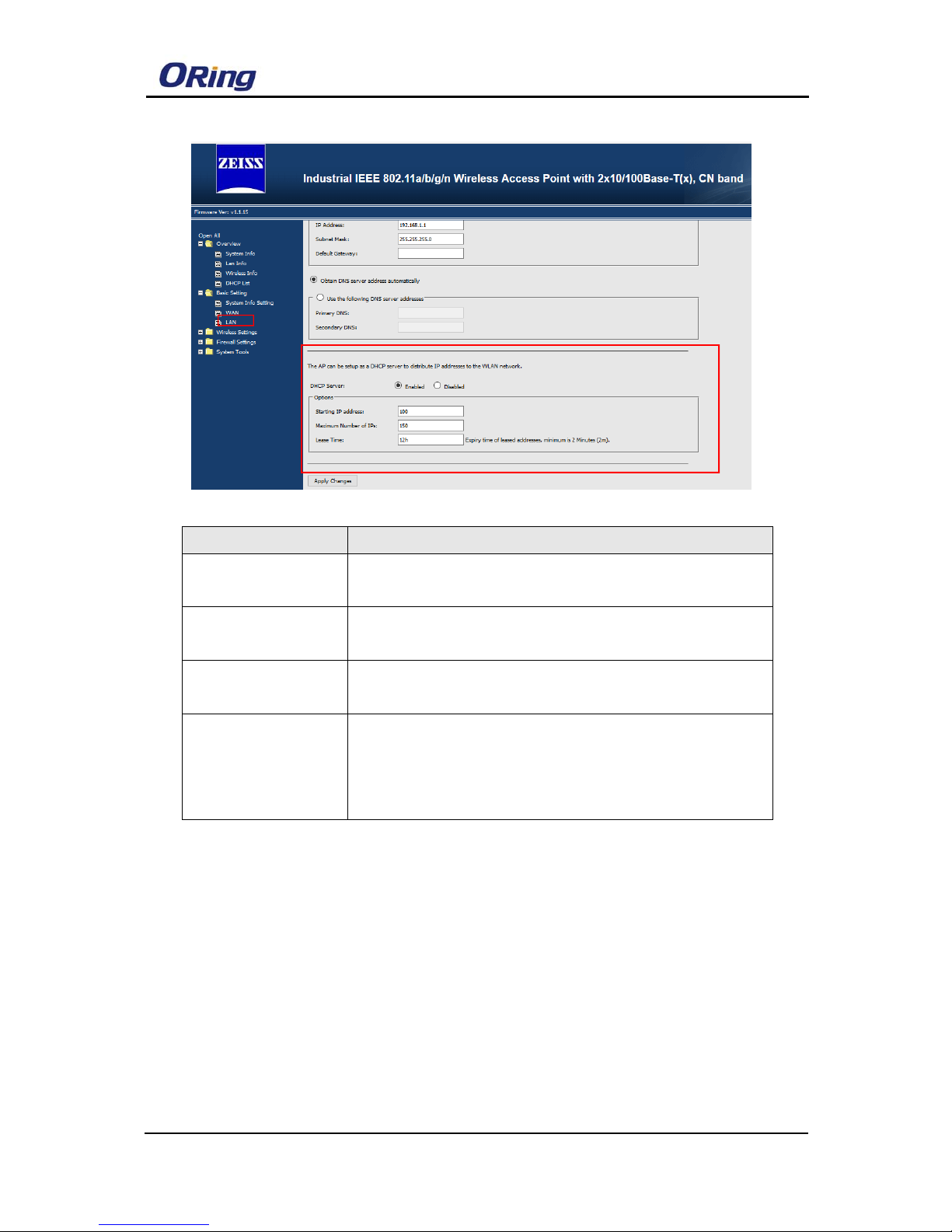
Label Description
DHCP Server Enable or Disable the DHCP Server function.
Note: DHCP Enable/Disable is configured by DIP Switch
Starting IP address: The dynamic IP assign range. Start IP address is the beginning
of the dynamic IP assigns range.
Maximum Number of
IPs:
The dynamic IP assign range. High IP address is the end of
the dynamic IP assigns range.
Lease time It is the time period that system will reset the dynamic IP
assignment to ensure the dynamic IP will not been occupied for
a long time or the server doesn’t know that the dynamic IP is
idle.
Page 10
WLAN 模块使用手册
ORing Industrial Networking Corp. 8
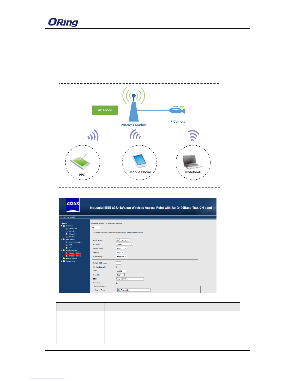
4. Wireless Setting
4.1 AP Mode
This mode provides Access Point services for other wireless clients
Label Description
Device Mode AP: Device plays the role of wireless Access Point
Client: Device plays the role of wireless Client
WDS: Device plays the role of wireless bridge
Notes: The default mode is AP Mode
Page 11
WLAN模块使用手册
9 ORing Industrial Networking Corp.
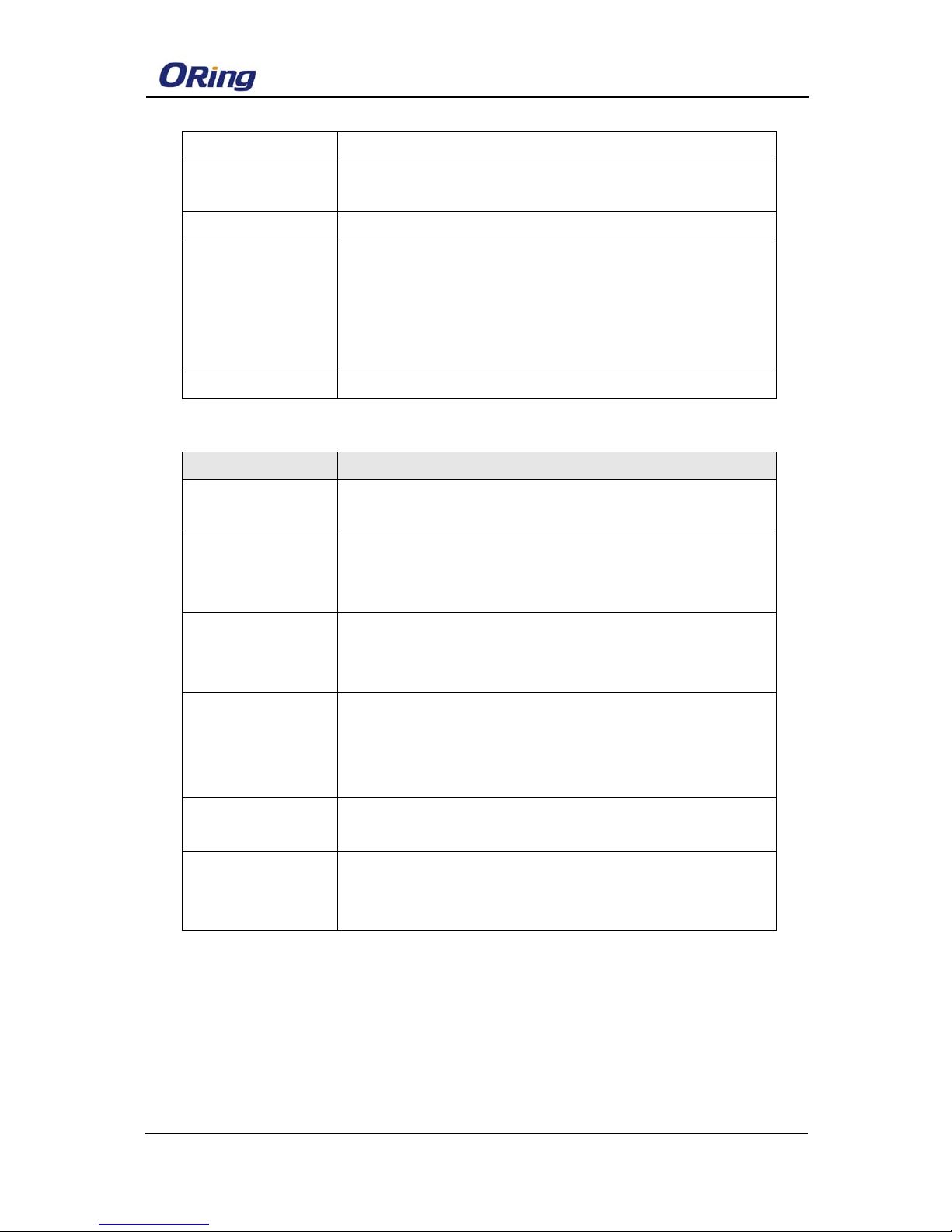
Wireless Mode Set wireless RF mode, the default setting is g/n mode
HT Mode
Select your channel width, If you are not sure which option to
use, select20/40 MHz(Auto)
TX Data Rate Set device transmit data rate
Channel
This option is only adjustable when the Device plays the
role of wireless AP ;If the device acts as a wireless client, it
follows the channel of the associated access point
Notes: The Default Channel is Auto in order to make the device
Scan the best free channel.
VLAN Setting Set Wireless VLAN port as untagged VLAN port
Label Description
Multiple SSID Index
You can configure the device to use up to 4 SSIDs, and configure
each SSID differently.
Wireless Disabled
Enable/Disable Wireless Function
Notes: You can Enable/Disable wireless function by Dip switch
“R”.
WMM
WMM is a QoS standard for WLAN traffic. Voice and video data
will be given priority bandwidth when enabled with WMM
supported wireless clients.
SSID
Service Set Identifier Default is the default setting. The SSID is
a unique name that identifies a network. All devices on the
network must share the same SSID name in order to
communicate on the network. If you change the SSID from the
HIDE SSID
Enable” HIDE SSID” function , then Wireless Client can’t scan the
device’s SSID
Security Option
Select the type of security for your wireless network at Security
Type: None/WEP/WPA/WPA2-Personal /WPA-PSK or
WPA2-PSK
Page 12
WLAN 模块使用手册
ORing Industrial Networking Corp. 10
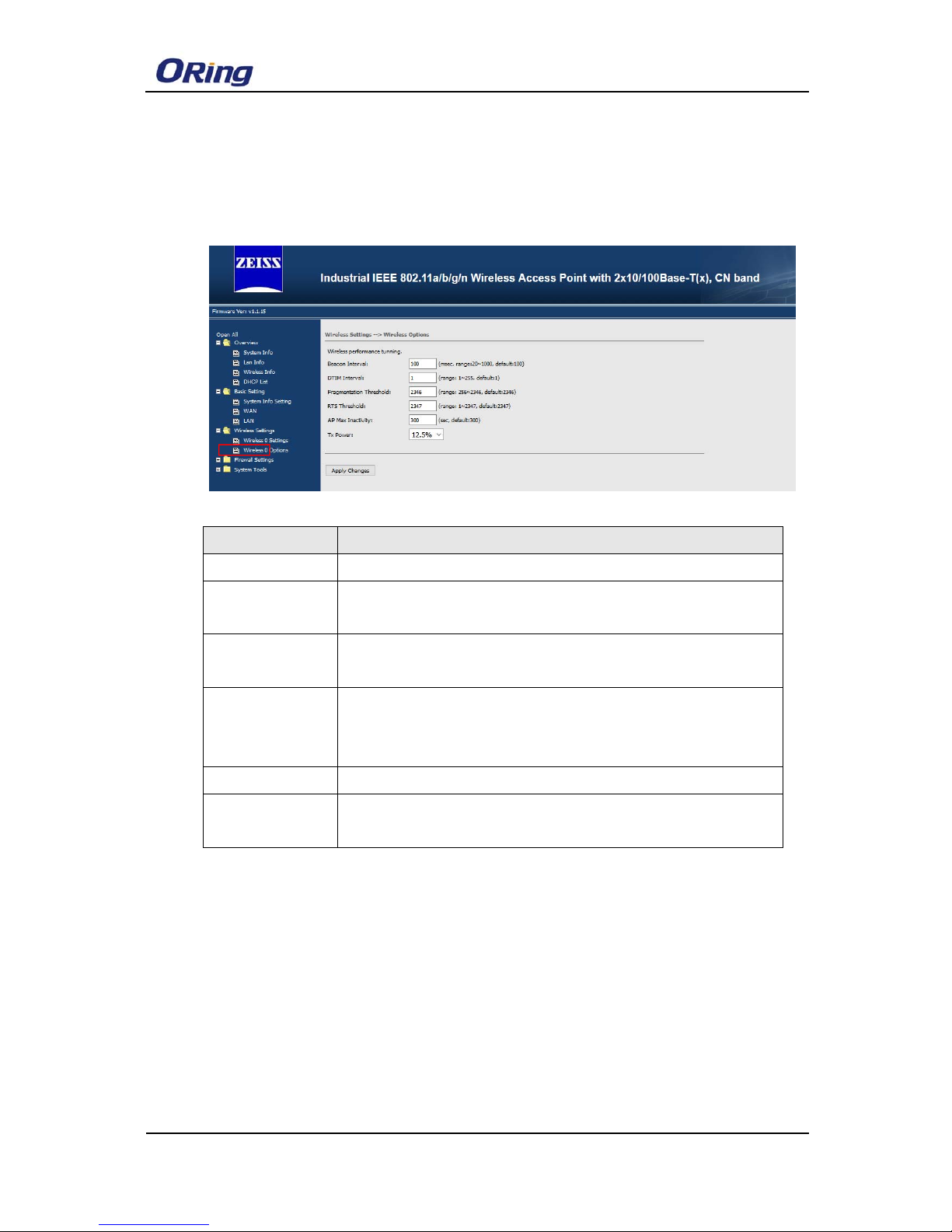
4.2 Wireless Option
Wireless Option related parameters are presented in this section to help you set
up your wireless network in detail
Label Description
Beacon Interval Indicates the frequency interval of the beacon
DTIM interval Indicates how often the device sends out a Delivery
Traffic Indication Message
Fragmentation
Threshold
Specifies the maximum size a data packet before splitting and
creating another new packet
RTS Threshold Determines how large a packet can be before the Access Point
coordinates transmission and reception to ensure efficient
communication
AP MAX Inactivity Specifies the maximum wireless client can connect the device
TX Power Users can manually select a target power to mask max output
power.
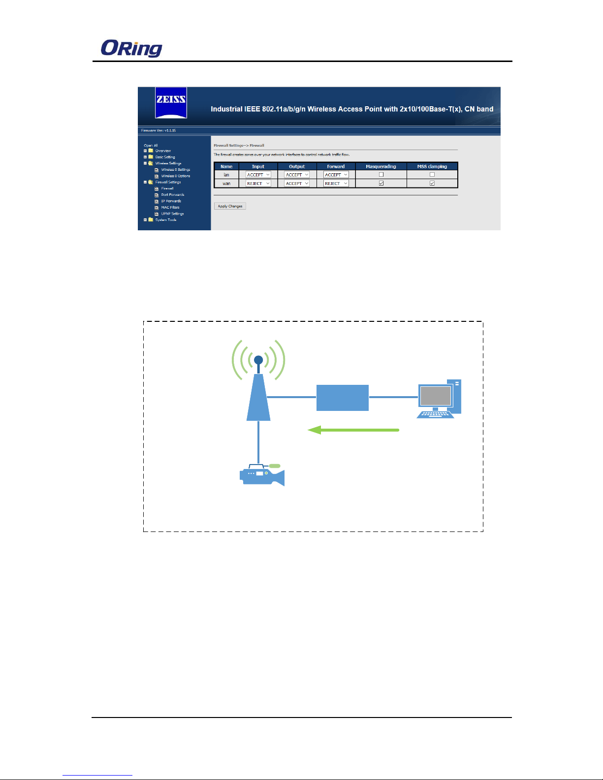
5. Firewall settings:
5.1 Firewall
You can set Firewall Rule to control the network traffic flow
Page 13
WLAN模块使用手册
11 ORing Industrial Networking Corp.
5.2 Port Forwards
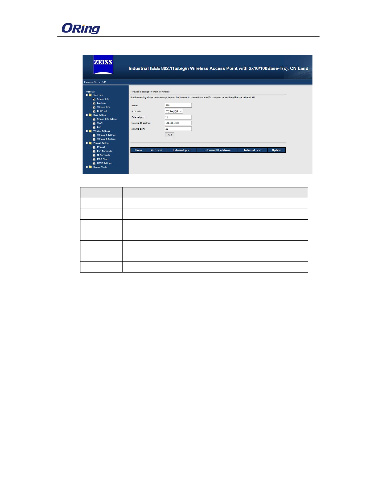
Port Forward can allow the external device access the internal device
application by device WAN IP address and TCP/UDP Number, for example: FTP,
Email….
LAN:IP:192.168.1.1/24
WAN:192.168.0.2/24
IPCamera
IP:192.168.1.100/24
Gateway:192.168.1.1
PC
IP:192.168.0.4/24
Switch
IAR-630-C
LAN
WAN
FTP://192.168.0.2:21
Page 14
WLAN 模块使用手册
ORing Industrial Networking Corp. 12
Label Description
Name Set the application Name
Protocol Set the data communication type TCP/UDP
External Port
IP
Enter external TCP/UDP number for External device access inter
Internal IP
address
Set the internal device IP address
Internal Port The Application use internal TCP/UDP number
Notes: As shown above Picture, the PC from external network can use
ftp application which provide from IP camera
5.2 IP Forwards
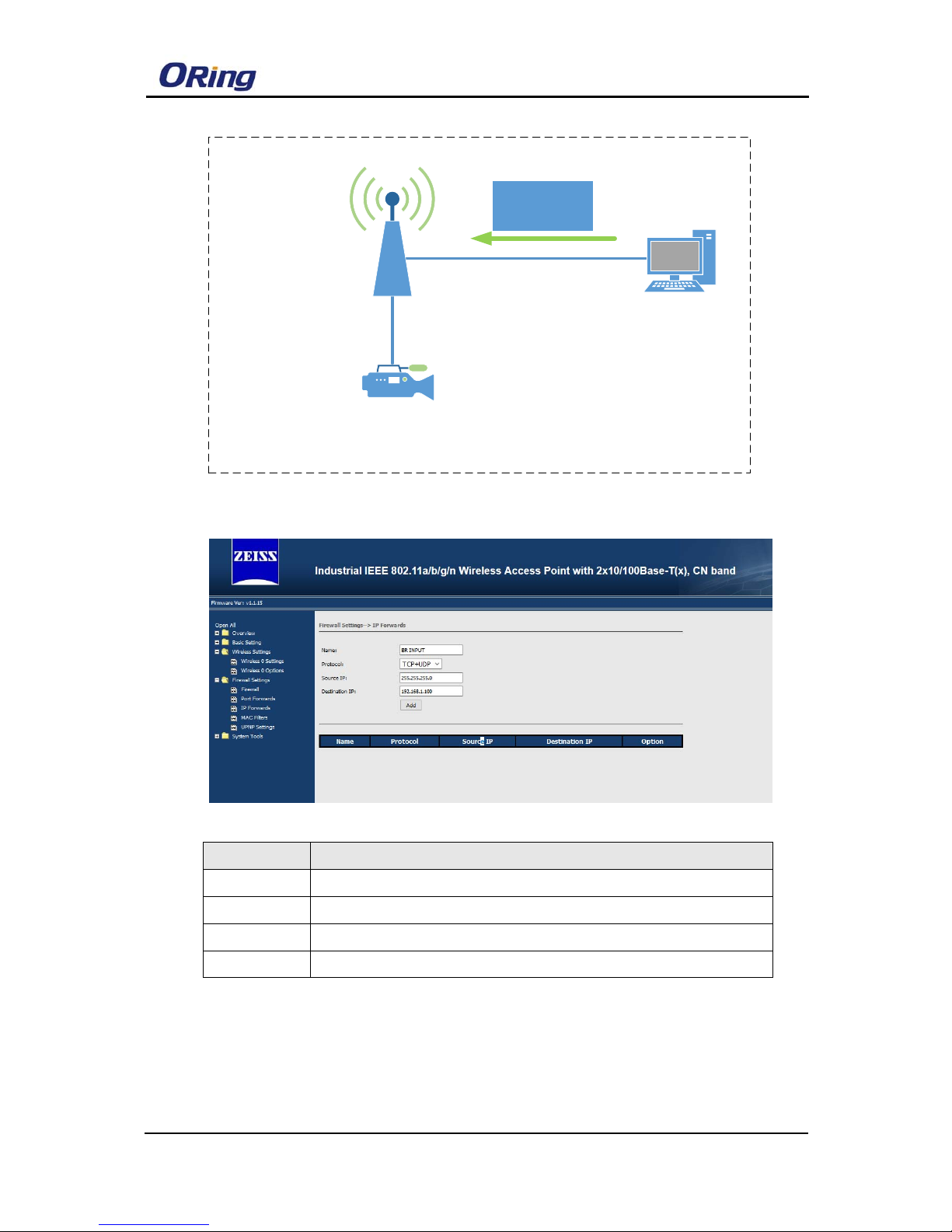
IP Forwards is a policy-based IP Address that allows specified “source IP
addresses” packets from the external WAN Device forwarded to specified the
destination IP address from internal device.
Page 15
WLAN模块使用手册
13 ORing Industrial Networking Corp.
LAN:IP:192.168.1.1/24
WAN:192.168.0.2/24
IPCamera
IP:192.168.1.100/24
Gateway:192.168.1.1
PC
IP:192.168.0.4/24
IAR-630-C
LAN
WAN
BroadcastPacket
Destnation:
25.255.255.0
Label Description
Name Set the application Name
Internal Port The packets used TCP/UDP number
Source IP The Packets Source IP address
Destination IP The Packets Destination IP address
Notes: As shown above picture, the packets with Destination IP
“255.255.255.0” sent by PC will be forwarded to the IP camera with
destination IP “192.168.1.100”
Page 16
WLAN 模块使用手册
ORing Industrial Networking Corp. 14
5.3 MAC Filters
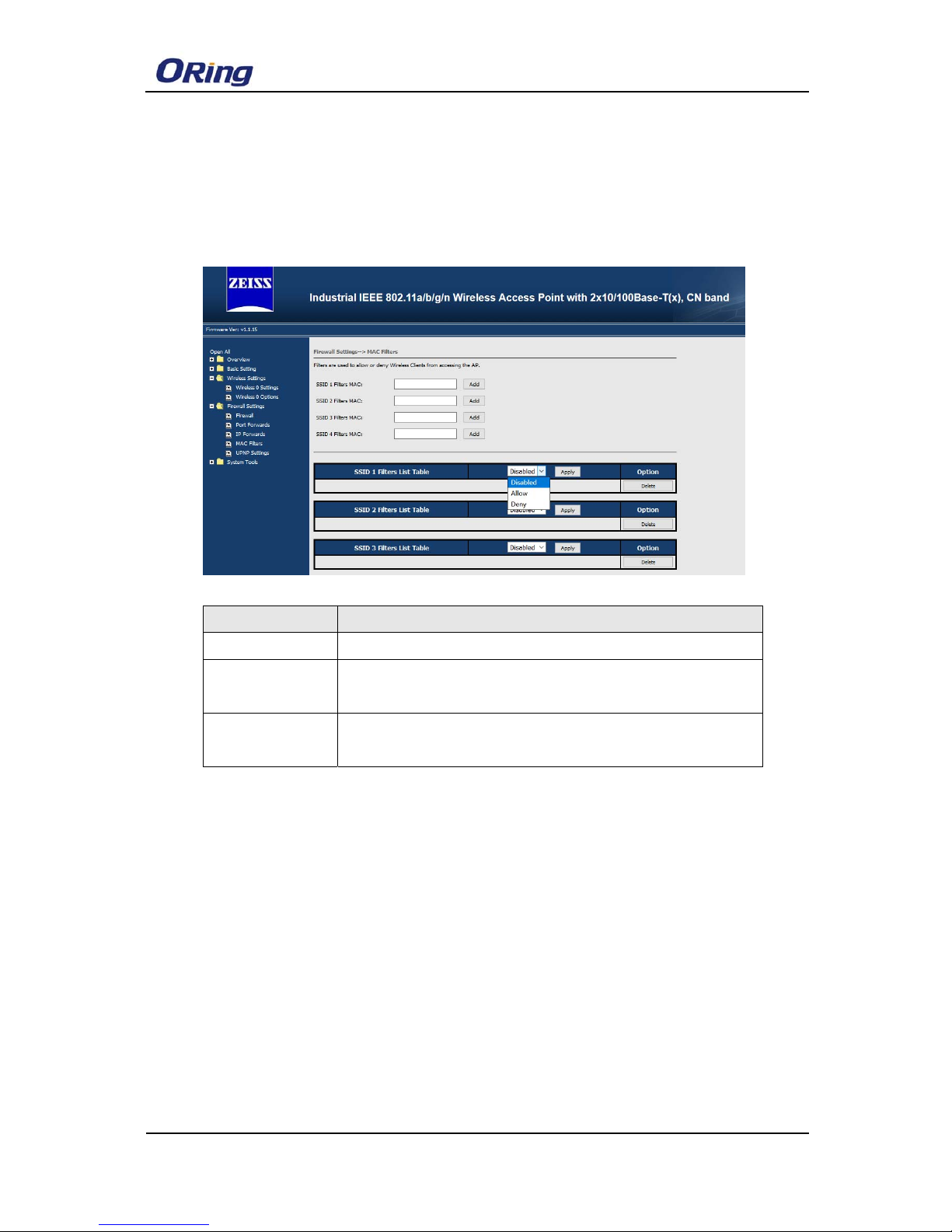
The device MAC filter is a policy-based filter that can allow or deny IP-based packets
with Specified MAC addresses to connect the device. The device can set different
policy by each SSID
.
Label Description
Disabled Disable Mac Filter policy
Allow List Only Only the wireless client fitting the entities on list can be allowed
to connect the device
Allow All Except
List
Only the wireless client fitting the entities on list will be deny to
connect the device
Page 17
WLAN模块使用手册
15 ORing Industrial Networking Corp.
5.2 UPNP
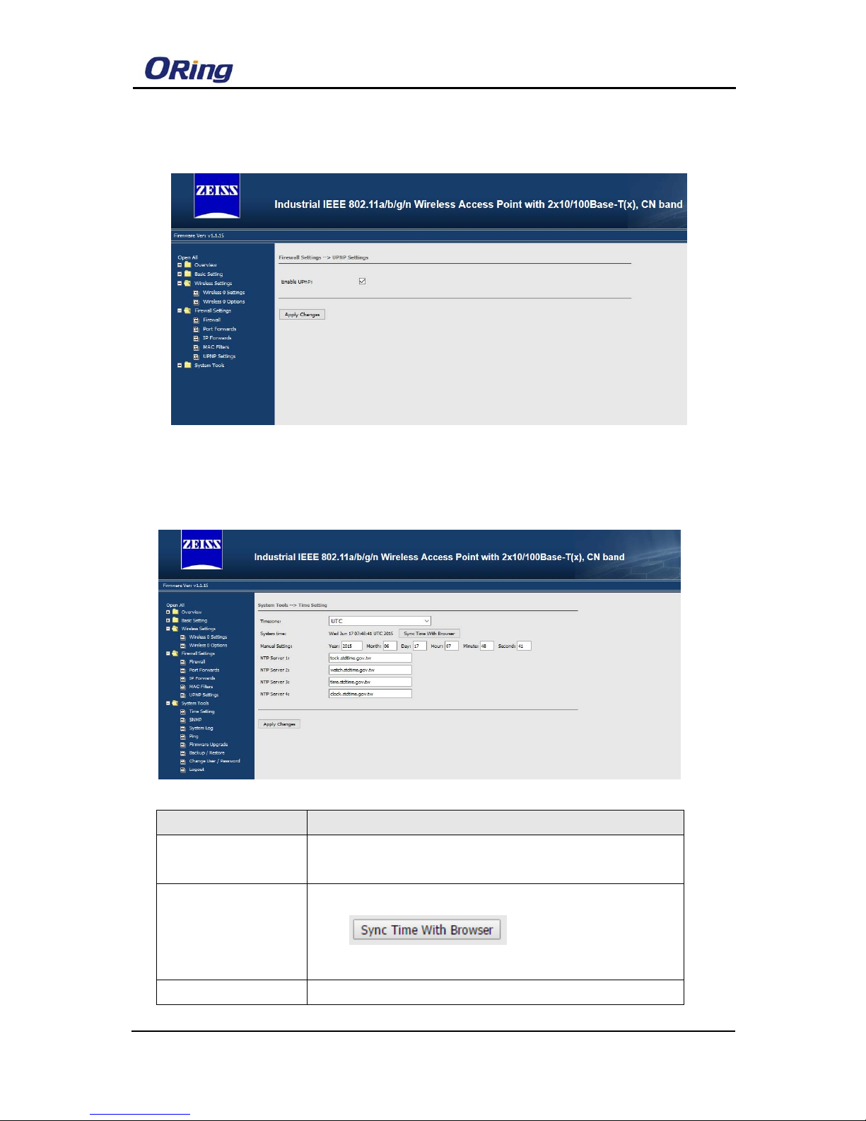
The Device support UPNP connect the Network
6. System Tools:
6.1Time Setting
Label Description
Timezone Set the timezone when you use NTP Server Synchronize the
time
System time Show the current system time ;
Click
Button,the device will sync
time with Browser
Manual setting You can set the device time manually.
Page 18
WLAN 模块使用手册
ORing Industrial Networking Corp. 16
NTP Server
The device also supports Synchronize the time from the NTP
server. Please enter the NTP Server IP address.
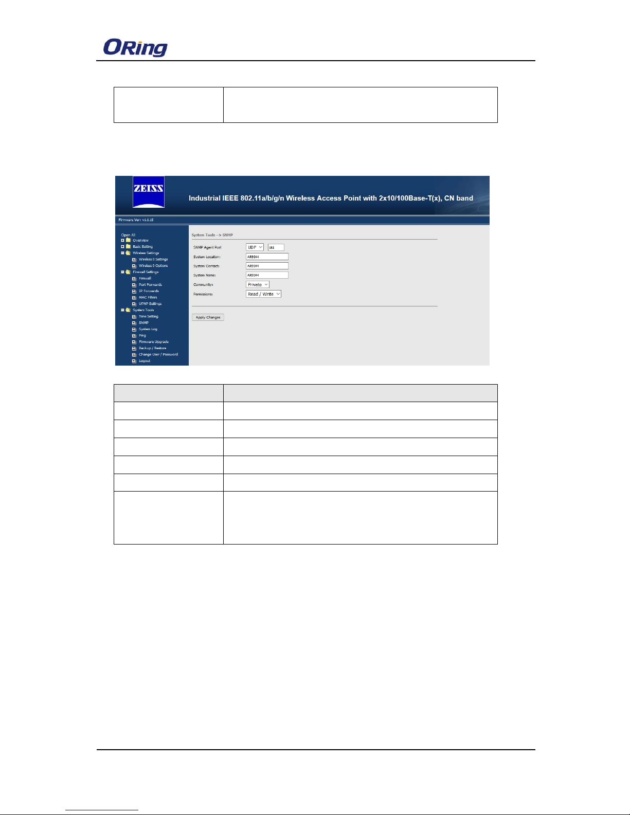
6.2 SNMP
Label Description
SNMP Agent Port Set SNMP Agent Port
System Location Set device location information
System Contact Set device contact people
System Name Set device name
Community Use a community string match for authentication
Permission
Set the community access Level :
Read: accesses all objects with read only
Read/Write: accesses all objects with read and writer
Page 19
WLAN模块使用手册
17 ORing Industrial Networking Corp.
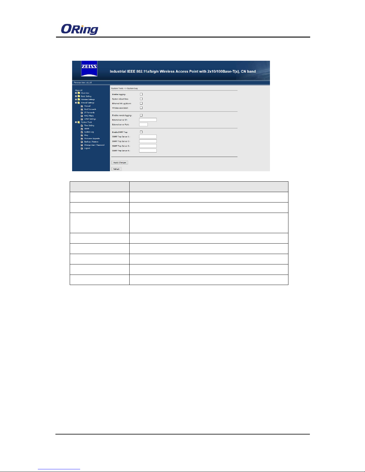
6.3 System Log
Label Description
Enable Logging provide system maintainers with real time log messages
System Reboot Time The device reboot
Ethernet Link
up/Down
The LAN port is connected or disconnected to a device or
network.
Wireless Associated The Wireless Client is connected to the Device
External Server IP Enter the external log server IP address
External Server Port Enter the external log server communication port
Enable SNMP Trap
Enable SNMP Trap alarm
SNMP Trap Server Enter the SNMP server IP address
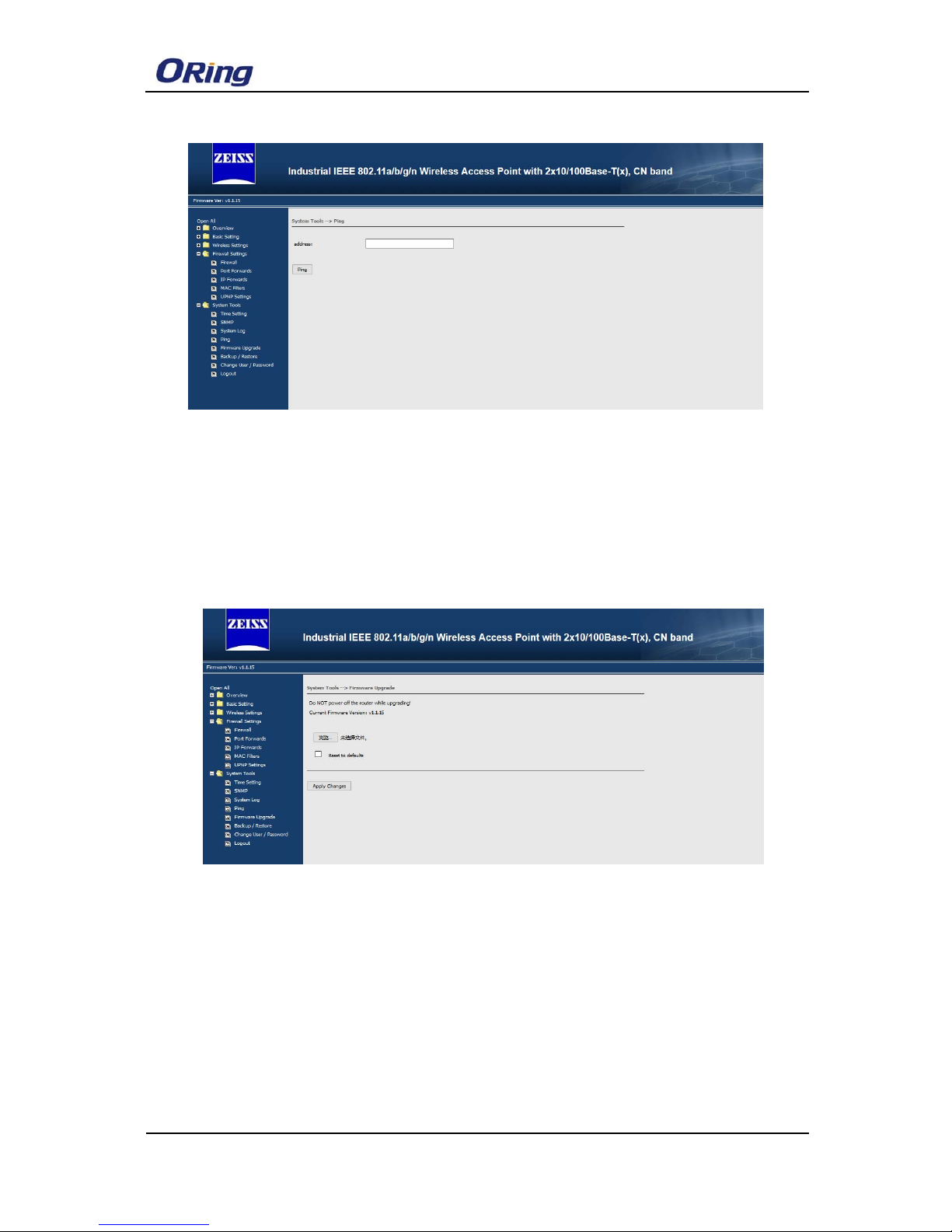
6.1 Ping
Ping helps to diagnose the integrity of wired or wireless networks. By inputting a
node’s IP address in the Address field, you can use the ping command to confirm it
exists and whether or not the access path is available
Page 20
WLAN 模块使用手册
ORing Industrial Networking Corp. 18
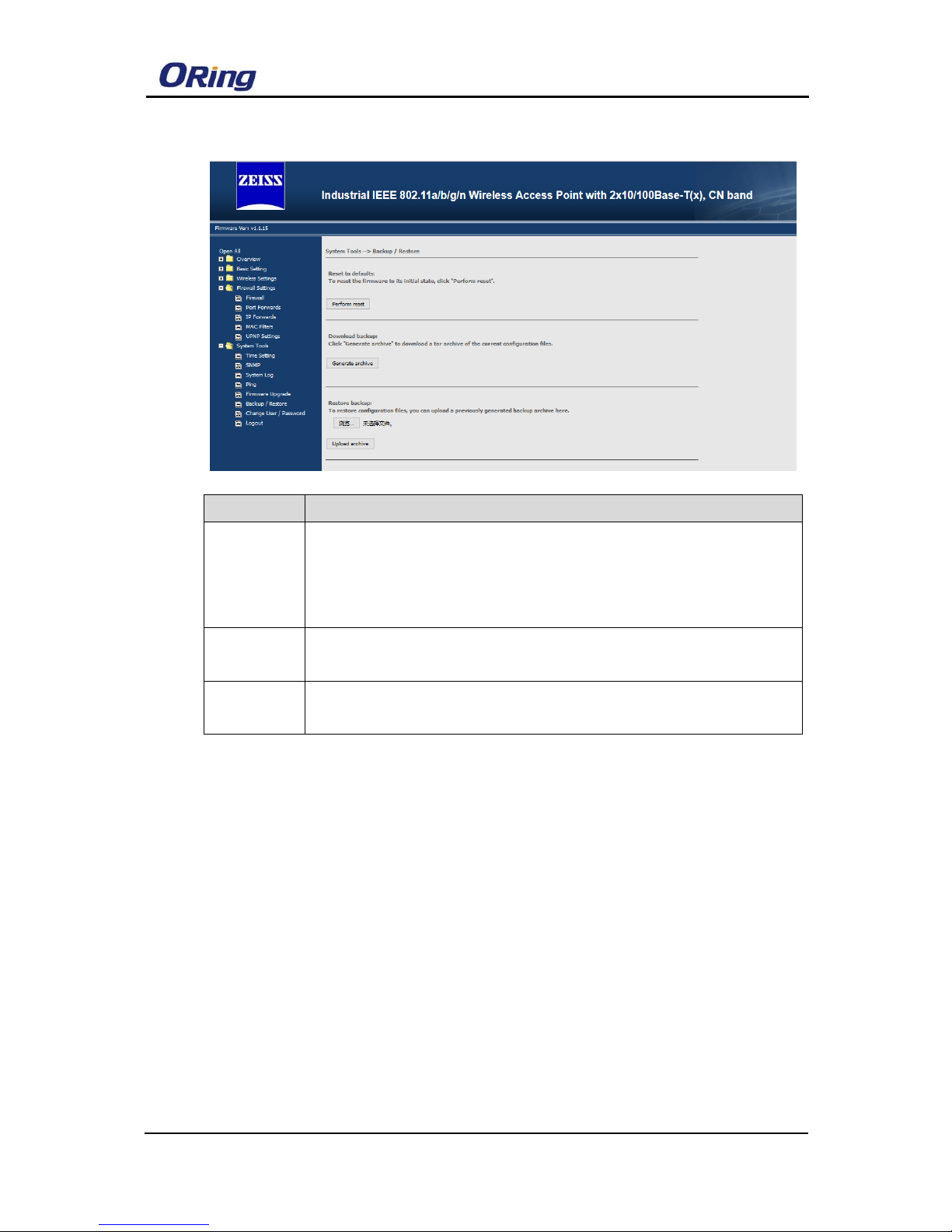
6.3 Firmware Upgrade
Before running a firmware upgrade, make sure the device is off-line. Click the
“Browse” button to specify the firmware image file and selected “reset to default
“ box, then Click “Apply changes” start the firmware upgrade. After the upgrade
finished, the device will reboot itself.
Attention: Please make sure the power source is stable when you upgrade your
firmware. An unexpected power breakup may damage your device
Page 21
WLAN模块使用手册
19 ORing Industrial Networking Corp.
6.4 Backup/Restore
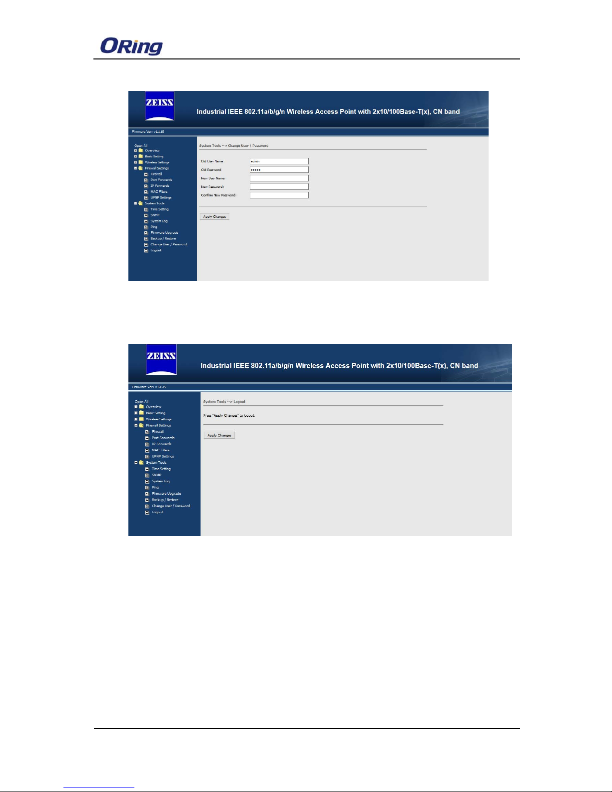
6.4 Change User/Password
You can change the administration password for each of the device by using the
Change User/Password function. Before you set up a new password, you must
input the current password and reenter the new password for confirmation.
Label Description
Reset to
default
Click “Perform reset “button to reset all settings back to the factory default
values. You can also reset the hardware by pressing the reset button on
the top panel of
the device.
Download
backup
Click“Generate archive“ button to save the configuration file
onto your local storage media
Restore
Backup
Browse to specify the configuration file and click “Upload Archive”button to
begin importing the configuration
Page 22
WLAN 模块使用手册
ORing Industrial Networking Corp. 20
6.4 Logout
Click “Apply change” to logout current configure page
Page 23

WLAN模块使用手册
21 ORing Industrial Networking Corp.
7. Compliance
FCC Statement
This device complies with Part 15 of the FCC Rules. Operation is subject to the following two
conditions:
(1) this device may not cause harmful interference and (2) this device must accept any
interference received, including interference that may cause undesired operation.
RF exposure warning: The equipment complies with RF exposure limits set forth for an
uncontrolled environment. The antenna(s) used for this transmitter must not be co-located or
operating in conjunction with any other antenna or transmitter.
You are cautioned that changes or modifications not expressly approved by the party
responsible for compliance could void your authority to operate the equipment. This device
should be operated with minimum distance 20cm between the device and all persons.
Industry Canada Statement
This device complies with Industry Canada licence-exempt RSS standard(s). Operation is
subject to the following two conditions: (1) this device may not cause interference, and (2) this
device must accept any interference, including interference that may cause undesired
operation of the device.
Le présent appareil est conforme aux CNR d'Industrie Canada applicable s aux appa reil s radi o
exempts de licence. L'exploitation est autorisée aux deux conditions suivantes : (1) l'appa reil
ne doit pas produire de brouillage, et (2) l'utilisateur de l'appareil doit accepter tout brouillage
radioélectrique subi, même si le brouillage est susceptible d'en compromettre le
fonctionnement.
Industry Canada - Class B This digital apparatus does not exceed the Class B limits for radio
noise emissions from digital apparatus as set out in the interference-causing equipment
standard entitled “Digital Apparatus,” ICES-003 of Industry Canada.
Cet appareil numérique respecte les limites de bruits radioélectriques applicable s au x
appareils numériques de Classe B prescrites dans la norme sur le matérial brouilleur:
“Appareils Numériques,” NMB-003 édictée par l’Industrie.
Operation is subject to the following two conditions: (1) this device may not cause interference,
Page 24

WLAN 模块使用手册
ORing Industrial Networking Corp. 22
and (2) this device must accept any interference, including interference that may cause
undesired operation of the device.
L'opération est soumise aux deux conditions suivantes: (1) cet ap pareil ne peut causer
d'interférences,et (2) cet appareil doit accepter toute interférence, y compris celles
susceptibles de provoquer fonctionnement du dispositif.
To reduce potential radio interference to other users, the antenna type and its gain should be
so chosen that the equivalent isotropically radiated power (e.i.r.p.) is not more than that
permitted for successful communication.
Afin de réduire les interférences radio potentielles pour les autres utilisateurs, le type
d'antenne et son gain doivent être choisie que la puissance isotrope rayonnée équivalente
(PIRE) est pas plus que celle premise pour une communication réu ssie
RF exposure warning: The equipment complies with RF exposure limits set forth for an
uncontrolled environment. The antenna(s) used for this transmitter must not be co-located or
operating in conjunction with any other antenna or transmitter.
Avertissement d'exposition RF: L'équipement est conforme aux limites d'exposition aux RF
établies pour un incontrôlés environnement. L'antenne (s) utilisée pour ce transmetteur ne
doit pas être co-localisés ou fonctionner en conjonction avec toute autre antenne ou
transmetteur.
 Loading...