

Page 1
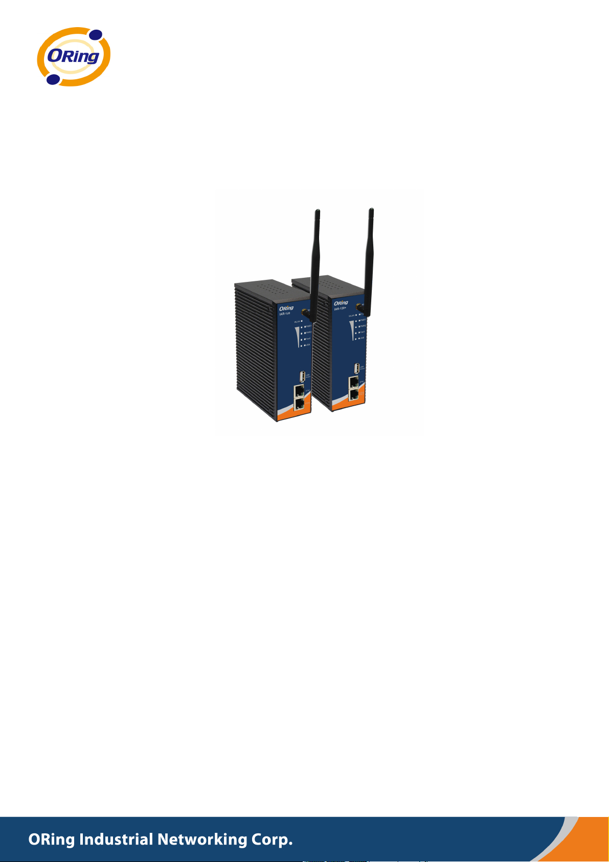
IIAARR--112200 sseerriieess
IIEEEEEE 880022..1111 bb//gg AAcccceessss PPooiinntt RRoouutteerr
UUsseerr’’ss M
Maannuuaall
VVeerrssiioonn 11..22
MMaarrcchh,, 22001111
wwwwww..oorriinngg--nneettwwoorrkkiinngg..ccoomm
Page 2

COPYRIGHT NOTICE
Copyright © 2011 ORing Industrial Networking Corp.
All rights reserved.
No part of this publication may be reproduced in any form without the prior written consent of
ORing Industrial Networking Corp.
TRADEMARKS
is a registered trademark of ORing Industrial Networking Corp.
All other trademarks belong to their respective owners.
REGULATORY COMPLIANCE STATEMENT
Product(s) associated with this publication complies/comply with all applicable regulations.
Please refer to the Technical Specifications section for more details.
WARRANTY
ORing warrants that all ORing products are free from defects in material and workmanship for a
specified warranty period from the invoice date (5 years for most products). ORing will repair or
replace products found by ORing to be defective within this warranty period, with shipment
expenses apportioned by ORing and the distributor. This warranty does not cover product
modifications or repairs done by persons other than ORing-approved personnel, and this
warranty does not apply to ORing products that are misused, abused, improperly installed, or
damaged by accidents.
Please refer to the Technical Specifications section for the actual warranty period(s) of the
product(s) associated with this publication.
DISCLAIMER
Information in this publication is intended to be accurate. ORing shall not be responsible for its
use or infringements on third-parties as a result of its use. There may occasionally be
unintentional errors on this publication. ORing reserves the right to revise the contents of this
publication without notice.
CONTACT INFORMATION
ORing Industrial Networking Corp.
3F., No.542-2, JhongJheng Rd., Sindian District, New Taipei City 23148, Taiwan (R.O.C.)
Tel: +886-2-2218-1066 // Fax: +886-2-2218-1014
Website: www.oring-networking.com
Technical Support
E-mail: [email protected]
Sales Contact
E-mail: [email protected]
(Headquarters)
(China)
Page 3

Tables of Content
Getting to Know your Wireless AP Router .................................................. 1
1.1 Overview .............................................................................................................................. 1
1.2 Software Features .............................................................................................................. 1
1.3 Hardware Features ............................................................................................................. 2
Hardware Installation .................................................................................... 3
2.1 Installation Router on DIN-Rail ......................................................................................... 3
2.2 Wall Mounting Installation .................................................................................................. 4
Hardware Overview ....................................................................................... 6
3.1 Front Panel .......................................................................................................................... 6
3.2 Front Panel LEDs ............................................................................................................... 8
3.3 Bottom Panel ....................................................................................................................... 9
3.4 Rear Panel ........................................................................................................................... 9
Cables and Antenna .................................................................................... 10
4.1 Ethernet Cables ................................................................................................................ 10
4.2 Wireless Antenna .............................................................................................................. 11
Management Interface ................................................................................ 12
5.1 First-time Installation ........................................................................................................ 12
5.2 Configure the Wireless Router ........................................................................................ 15
5.3 Main Interface .................................................................................................................... 15
5.3.1 Basic Setting ................................................................................................................... 16
WAN ........................................................................................................................................ 16
LAN ......................................................................................................................................... 21
DHCP ....................................................................................................................................... 22
Wireless .................................................................................................................................... 24
5.3.2 Advanced Setting ............................................................................................................ 28
Wireless .................................................................................................................................... 28
NAT Setting .............................................................................................................................. 31
Security Setting ........................................................................................................................ 35
VPN Setting ............................................................................................................................. 36
Routing Protocol (Routing Setting) .......................................................................................... 43
Notification .............................................................................................................................. 46
Miscellaneous (DDNS) ............................................................................................................ 48
5.3.3 System Tools ................................................................................................................... 49
Date & Time ............................................................................................................................. 49
Login Setting ............................................................................................................................ 50
Router Restart .......................................................................................................................... 51
Page 4

Firmware Upgrade ................................................................................................................... 51
Save/Restore Configurations .................................................................................................... 52
Miscellaneous (Ping) ................................................................................................................ 53
5.3.4 System Status .................................................................................................................. 54
System Info .............................................................................................................................. 54
System Log .............................................................................................................................. 54
Traffic Statistics ....................................................................................................................... 55
Wired/Wireless Clients ............................................................................................................. 55
Technical Specifications ............................................................................. 56
Page 5

IAR-120 / 120+ User’s Manual
Getting to Know your Wireless AP
Router
1.1 Overview
The ORing IAR-120 / 120+ wireless AP router is designed to
operate in industrial environment. The AP router provides a
fast and effective ways of communicating to the internet over
wired or wireless LAN. In addition, multiple types of WAN
connection are provided for easily access to the internet.
The ORing IAR-120 / 120+ wireless AP router is IEEE802.11g
high-performance wireless equipment which is also compatible
with IEEE802.11b equipment. It is capable of data transfer
rates up to 54Mbps. It is easy for you to extend the reach and
number of computers connected to your wireless network.
With the USB 3G WAN connection, the ORing IAR-120 / 120+ wireless AP router can be
mounted in harsh environment easily to provide internet access anytime and anywhere.
The ORing IAR-120 / 120+ wireless AP router's VPN capability creates encrypted "Virtual
Tunnels" through the internet, allowing remote or traveling users for secured connection
with the network in your office.
1.2 Software Features
Intuitive Web-based management user interface for simply and easily operation.
USB connectivity providing Internet access via the USB to RS232 convertor + modem
or 3G HSDPA module (HUAWEI E220) directly.
Functions of firewall provides many security features such as blocking attacks from
hacker, especially IP Spoofing, Ping flood, Ping of Death, DOS, DRDOS, Stealth Scan,
ICMP flooding etc.
Advanced firewall configuration to extend the capability and security, such as Virtual
Server, Port Trigger, DMZ host, UPnP auto Forwarding, IP Filter and MAC filter.
ORing Industrial Networking Corp. 1
Page 6

IAR-120 / 120+ User’s Manual
1.3 Hardware Features
Two 10/100Base-T(X) Ethernet ports for WAN / LAN connection individually.
Fully Compliant with IEEE802.3af (Power Device at ETH2, WAN port, IAR-120+ only)
Redundant Power Inputs: 12~48 VDC on terminal block
Casing: IP-30
Dimensions(W x D x H) : 52 mm(W)x 106.1 mm(D)x 144.3 mm(H)
Operating Temperature: -10 to 55
Storage Temperature: -40 to 85
Operating Humidity: 5% to 95%, non-condensing
o
C
o
C
ORing Industrial Networking Corp. 2
Page 7

IAR-120 / 120+ User’s Manual
Hardware Installation
2.1 Installation Router on DIN-Rail
Each Wireless AP router has a DIN-Rail kit on rear panel. The DIN-Rail kit helps AP
router to fix on the DIN-Rail.
Step 1: Slant the router and mount the metal spring to DIN-Rail.
Step 2: Push the router toward the DIN-Rail until you heard a “click” sound.
Metal Spring
ORing Industrial Networking Corp……………………………………………………………….…3
Page 8
IAR-120 / 120+ User’s Manual
2.2 Wall Mounting Installation
Each AP router has another installation method to fix the AP router. A wall mount
panel can be found in the package. The following steps show how to mount the AP router
on the wall:
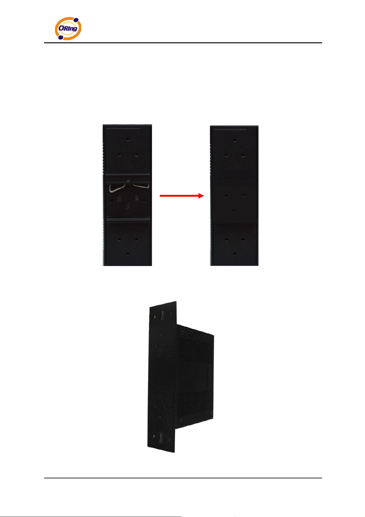
Step 1: Remove DIN-Rail kit.
Step 2: Use 6 screws that can be found in the package to combine the wall mount panel.
Just like the picture shows below:
ORing Industrial Networking Corp. 4
Page 9

IAR-120 / 120+ User’s Manual
The screws specification shows in the following two pictures. In order to prevent the
AP routers from any damage, the screws should not larger than the size that used in
IAR-120 / 120+.
Pozidrive
ORing Industrial Networking Corp……………………………………………………………….…5
Page 10

IAR-120 / 120+ User’s Manual
Hardware Overview
3.1 Front Panel
The following table describes the labels that stick on the IAR-120 / 120+.
Port Description
10/100 RJ-45 fast
Ethernet ports
P.O.E. PD Port
ANT.
*Note: Please refer to the products of ORing IPS series for P.O.E. Ethernet switch.
2 10/100Base-T(X) RJ-45 fast Ethernet ports support
auto-negotiation.
Default Setting :
Speed: auto
Duplex: auto
ETH2 (WAN port) of IAR-120+ compliant with IEEE802.3af P.O.E.
specifications and can be connected to P.O.E. switches.*
Reversed SMA connector for external antenna.
ORing Industrial Networking Corp. 6
Page 11
IAR-120 / 120+ User’s Manual
IAR-120 IAR-120+
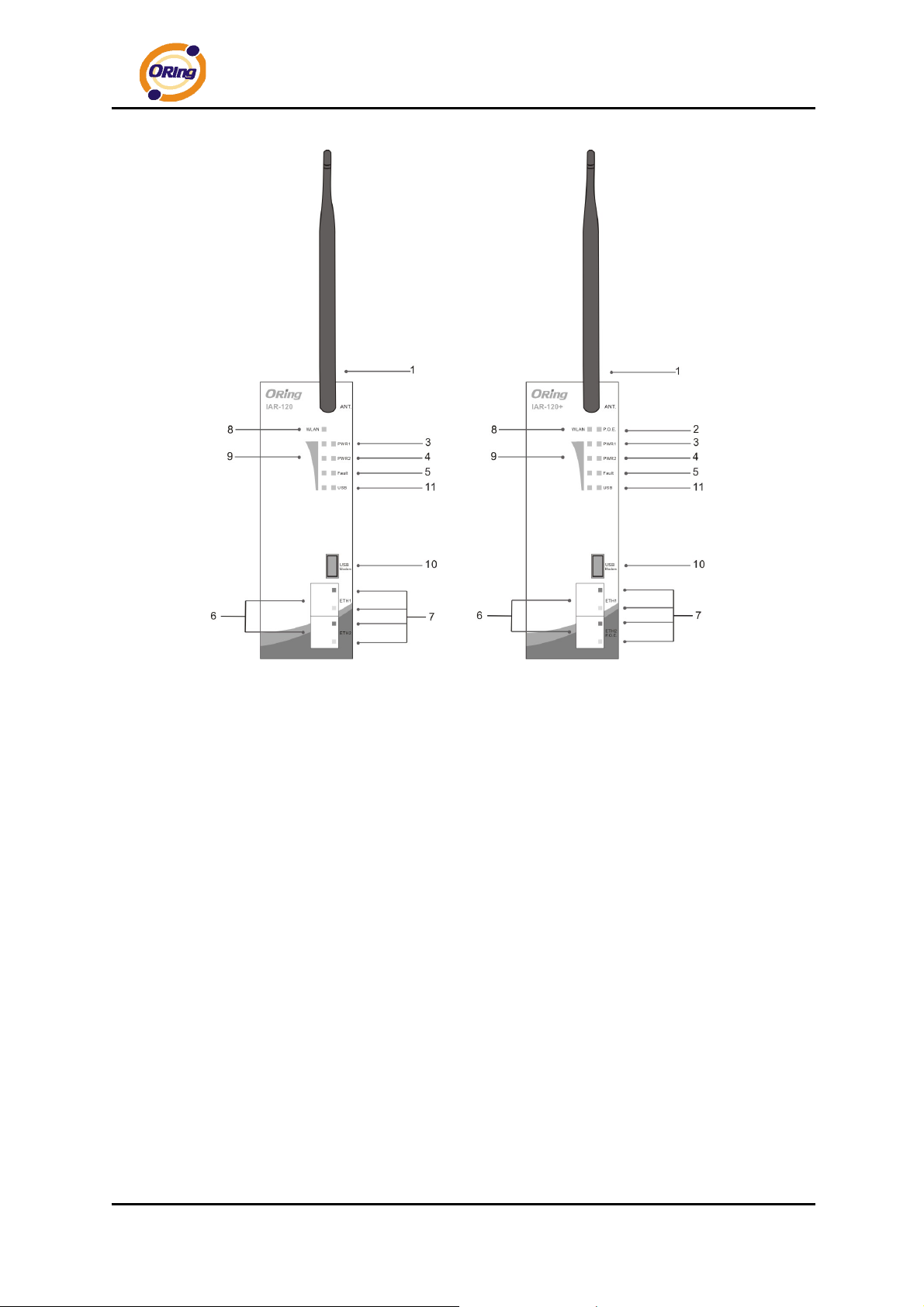
1. 2.4GHz antenna with typical 2.0dbi antenna.
2. LED for P.O.E. power and system status. When the P.O.E. power links, the green
led will be light on.
3. LED for PWR1 and system status. When the PWR1 links, the green led will be light
on.
4. LED for PWR2 and system status. When the PWR2 links, the green led will be light
on.
5. LED for Fault indication. When the fault event occurs, the amber LED will be light
on.
6. 10/100Base-T(X) Ethernet ports. ETH1 for LAN port and ETH2 for WAN port.
(IAR-120+ contains PD function of P.O.E. at ETH2)
7. LED for Ethernet ports status.
8. LED for WLAN link/act status.
9. LED for WLAN signal strength.
10. USB port for 3G USB modem connection.
11. LED for USB modem status
ORing Industrial Networking Corp……………………………………………………………….…7
Page 12
IAR-120 / 120+ User’s Manual
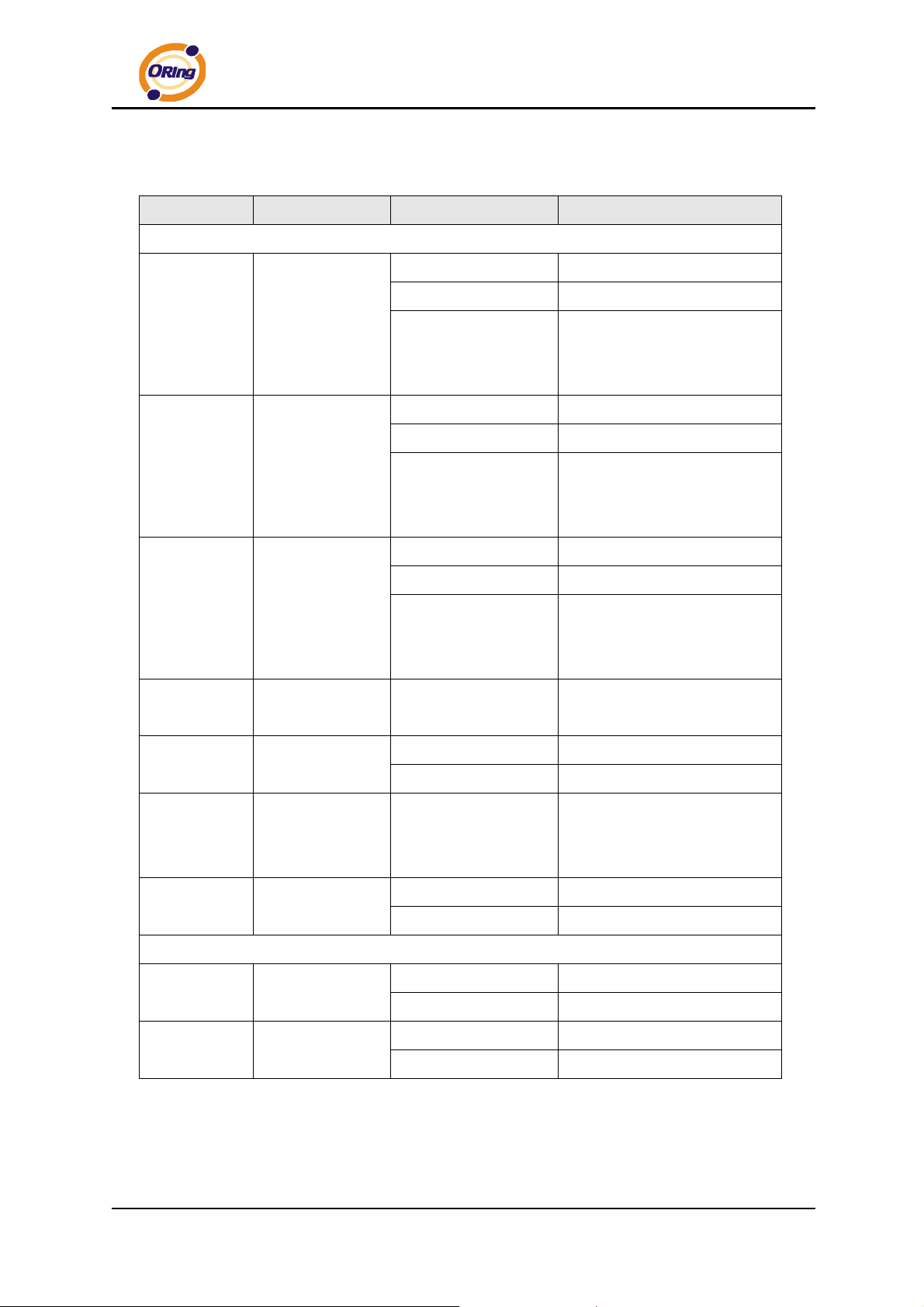
3.2 Front Panel LEDs
LED Color Status Description
System LED
Green On P.O.E. power connected.
Green blinking Device been located
P. O .E .
PWR1
PWR2
Fault
WLAN
Green / Red
Red blinking
Green On DC power 1 activated.
Green blinking Device been located
Green / Red
Red blinking
Green On DC power 2 activated.
Green blinking Device been located
Green / Red
Red blinking
Amber On
On WLAN activated.
Green
Blinking WLAN Data transmitted.
Indicates an IP conflict, or
DHCP or BOOTP server did
not respond properly
Indicates an IP conflict, or
DHCP or BOOTP server did
not respond properly
Indicates an IP conflict, or
DHCP or BOOTP server did
not respond properly
Fault relay. Power failure
or Port link down.
WLAN
Strength
USB
Status
10/100Base-T(X) Fast Ethernet ports
10Mbps
LNK/ACT
100Mbps
LNK/ACT
ORing Industrial Networking Corp. 8
Green On
On Modem Ready
Green
Blinking Checking Modem status
On Port link up at 10Mbps.
Amber
Blinking Data transmitted.
On Port link up at 100Mbps.
Green
Blinking Data transmitted.
WLAN signal strength.
1<25%, 2<50%, 3<75%,
4<100%
Page 13
IAR-120 / 120+ User’s Manual
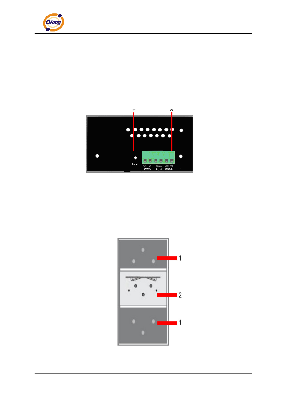
3.3 Bottom Panel
The bottom panel components of IAR-120 / 120+ are shown as below:
1. Terminal block includes: PWR1, PWR2 (12 ~ 48V DC) and Relay output (1A@24VDC).
2. Reset button. Push the bottom 3 seconds for reset; 5 seconds for factory default.
PWR1, PWR2 (12-48V DC) and
Reset Button Relay output (1A@24VDC).
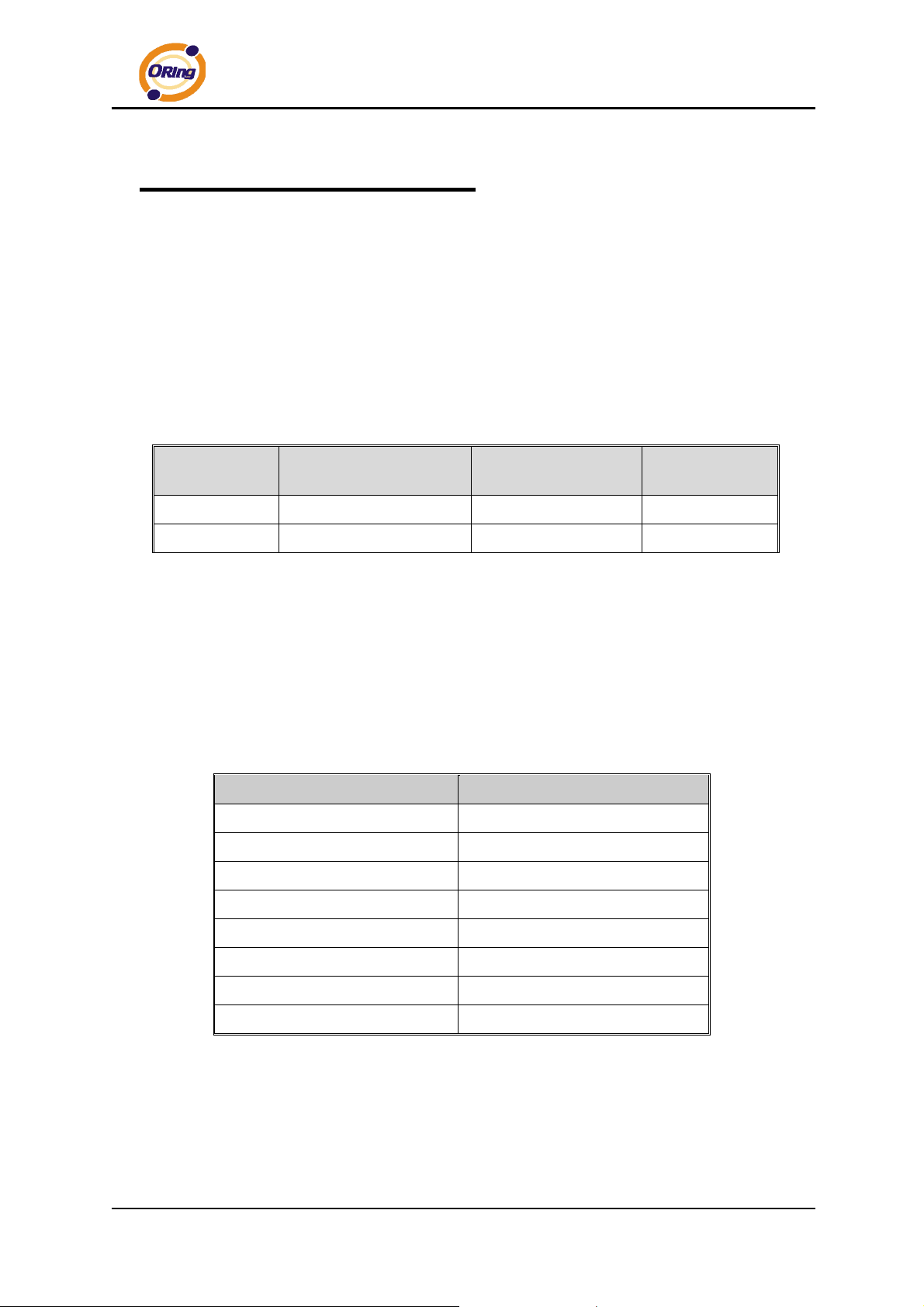
3.4 Rear Panel
The rear panel components of IAR-120 / 120+ are shown as below:
1. Screw holes for wall mount kit.
2. DIN-Rail kit
ORing Industrial Networking Corp……………………………………………………………….…9
Page 14
IAR-120 / 120+ User’s Manual
Cables and Antenna
4.1 Ethernet Cables
The IAR-120 / 120+ AP routers have standard Ethernet ports. According to the link type,
the routers use CAT 3, 4, 5, 5e UTP cables to connect to any other network device (PCs,
servers, switches, routers, or hubs). Please refer to the following table for cable
specifications.
Cable Types and Specifications
Cable Type Max. Length Connector
10BASE-T Cat. 3, 4, 5 100-ohm UTP 100 m (328 ft) RJ-45
100BASE-TX Cat. 5 100-ohm UTP UTP 100 m (328 ft) RJ-45
100BASE-TX/10BASE-T Pin Assignments
With 100BASE-TX/10BASE-T cable, pins 1 and 2 are used for transmitting data, and
pins 3 and 6 are used for receiving data.
RJ-45 Pin Assignments
Pin Number Assignment
1 TD+
2 TD-
3 RD+
4 Not used
5 Not used
6 RD-
7 Not used
8 Not used
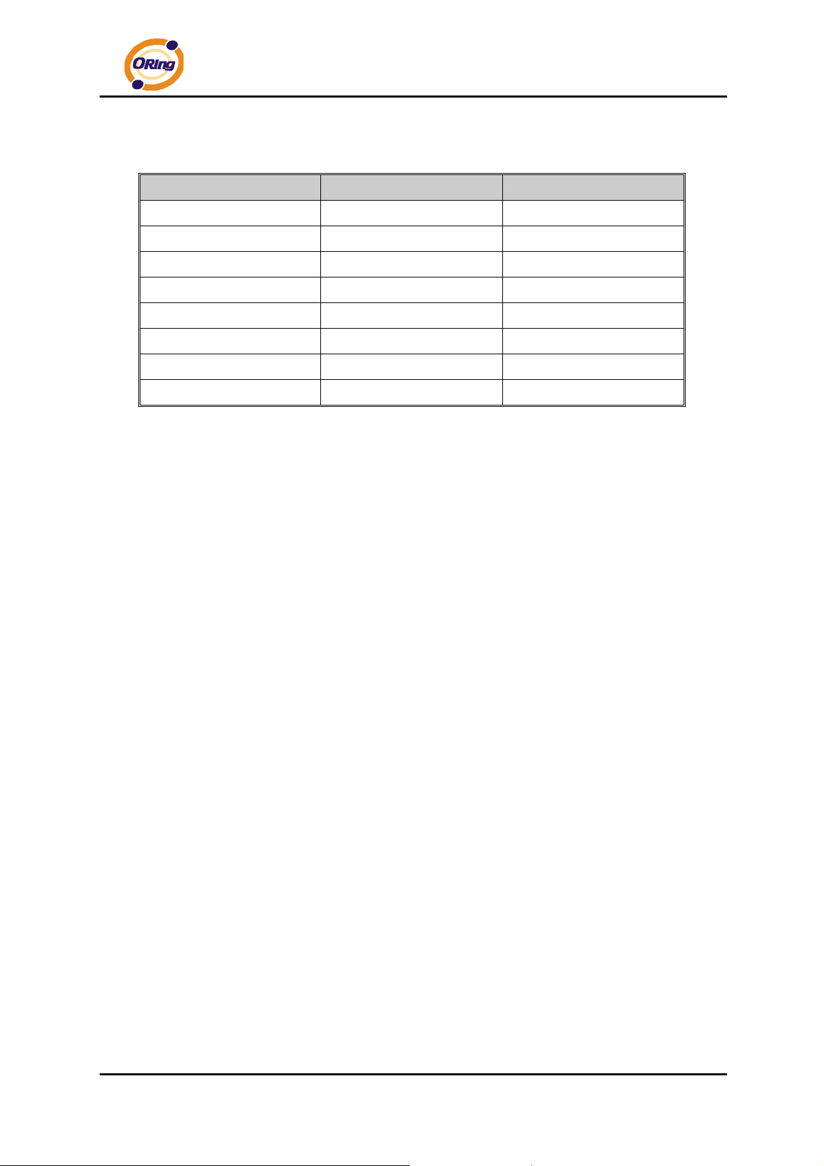
The IAR-120 / 120+ routers support auto MDI/MDI-X operation. You can use a
straight-through cable to connect PC and router. The following table below shows the
10BASE-T/ 100BASE-TX MDI and MDI-X port pin outs.
ORing Industrial Networking Corp. 10
Page 15
IAR-120 / 120+ User’s Manual
MDI/MDI-X pins assignment
Pin Number MDI port MDI-X port
1 TD+(transmit) RD+(receive)
2 TD-(transmit) RD-(receive)
3 RD+(receive) TD+(transmit)
4 Not used Not used
5 Not used Not used
6 RD-(receive) TD-(transmit)
7 Not used Not used
8 Not used Not used
Note: “+” and “-” signs represent the polarity of the wires that make up each wire pair.
4.2 Wireless Antenna
A 2.4GHz antenna is used for IAR-120 / 120+ and connected with a reversed SMA connector.
External antenna also can be applied with this connector.
ORing Industrial Networking Corp……………………………………………………………….…11
Page 16
IAR-120 / 120+ User’s Manual
Management Interface
5.1 First-time Installation
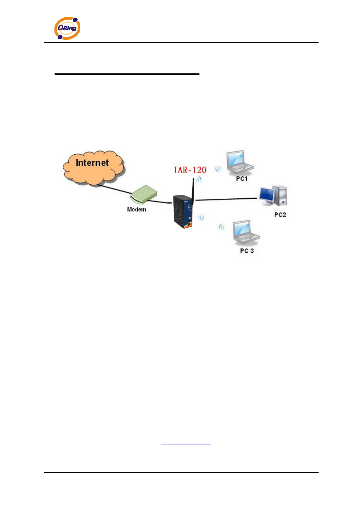
Before installing IAR-120 / 120+ WLAN AP router, you need to access the WLAN AP
router by a computer equipped with an Ethernet card or wireless LAN interface. Using an
Ethernet card to connect to LAN port is easier and recommended.
Basic connection for IAR-120 / 120+
Step 1: Select the Power Source
IAR-120 / 120+ AP router can be powered by +12~48V DC power input, or by P.O.E.
(Power over Ethernet) PSE Ethernet switch.
Step 2: Connect a computer to IAR-120 / 120+
Use either a straight-through Ethernet cable or cross-over cable to connect to ETH1 of
IAR-120 / 120+ AP router to a computer. If the LED of the LAN port lights up, it indicates
the connection is established. After that, the computer will initiate a DHCP request to get
an IP address from the AP router.
Step 3: Use the web-based manager to configure IAR-120 / 120+
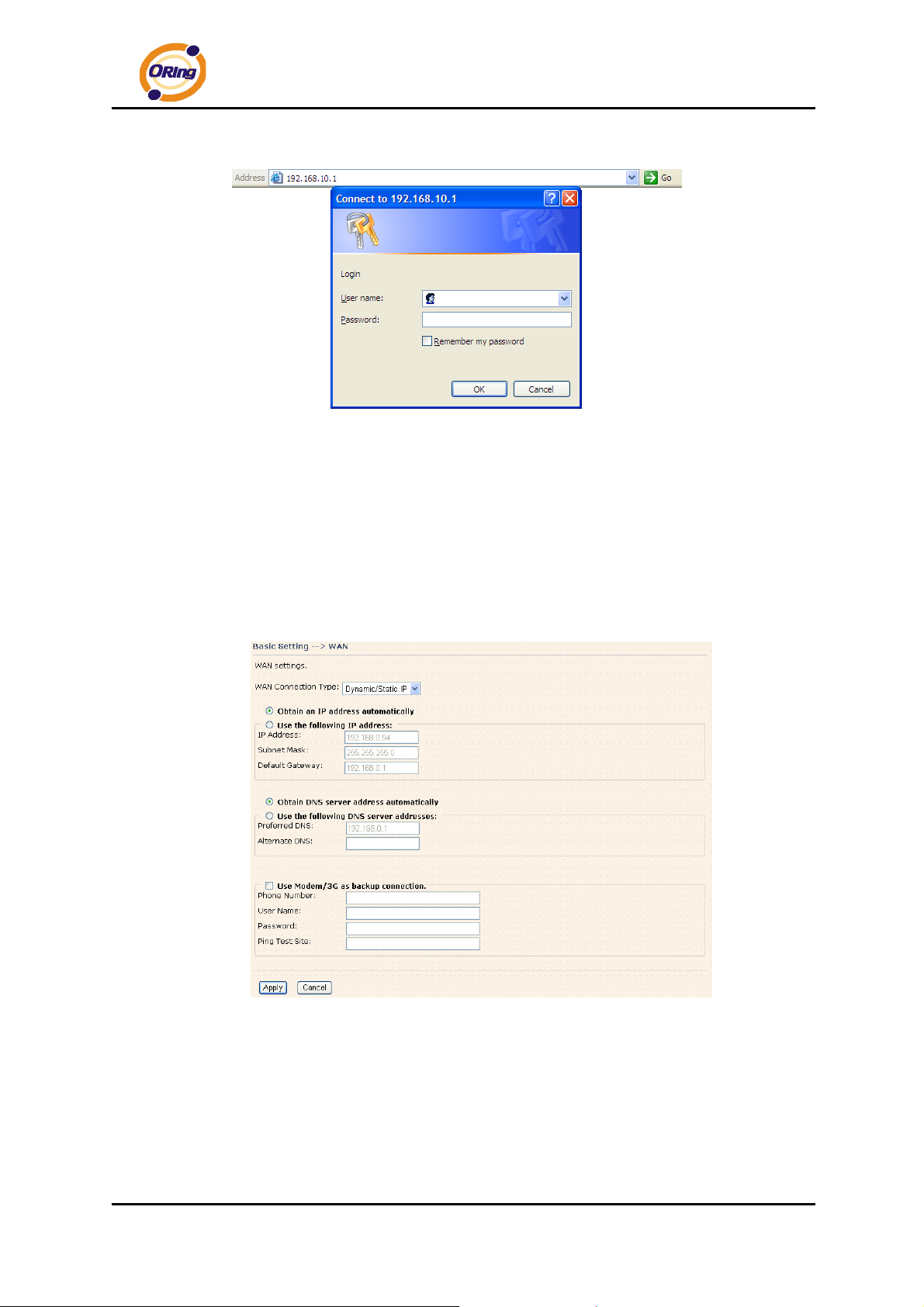
The default gateway IP of IAR-120 / 120+ AP router is 192.168.10.1. Start the web
browser of your computer and type http://192.168.10.1
webpage. A login window will popup, and then enter the default login name admin and
ORing Industrial Networking Corp. 12
in the address box to access the
Page 17
IAR-120 / 120+ User’s Manual
password admin.
Login screen
Step 4: Select WAN connection type
Click the Basic Setting in the top menu to enter the WAN configuration page, select the
proper connection type according to the information of your ISP. If you use modem/3G as
WAN connection, please plug in your USB to RS232 converter with modem or 3G USB
modem directly (HUAWEI E220 is supported).
WAN connection type
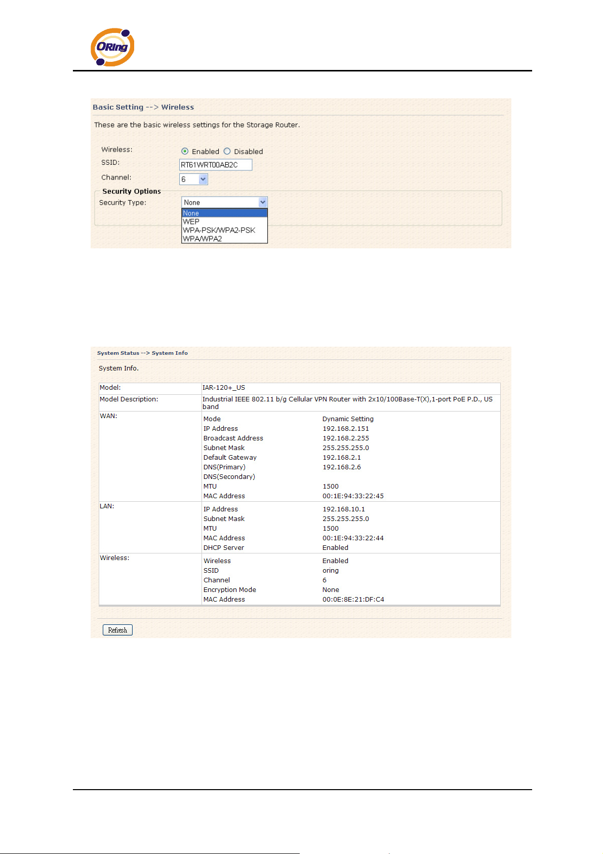
Step 5: Protect the wireless access in encryption mode
Click the Wireless in Basic Setting menu, default encryption mode is None, choose
WEP/WPA to enhance the security of wireless connection.
ORing Industrial Networking Corp……………………………………………………………….…13
Page 18
IAR-120 / 120+ User’s Manual
Wireless security option
Step 6: Review the router settings and check router status
Click the System Status in the top of the menu, the system info page will be shown.
You can check all the configuration and status of the router.
System status Screen
ORing Industrial Networking Corp. 14
Page 19
IAR-120 / 120+ User’s Manual
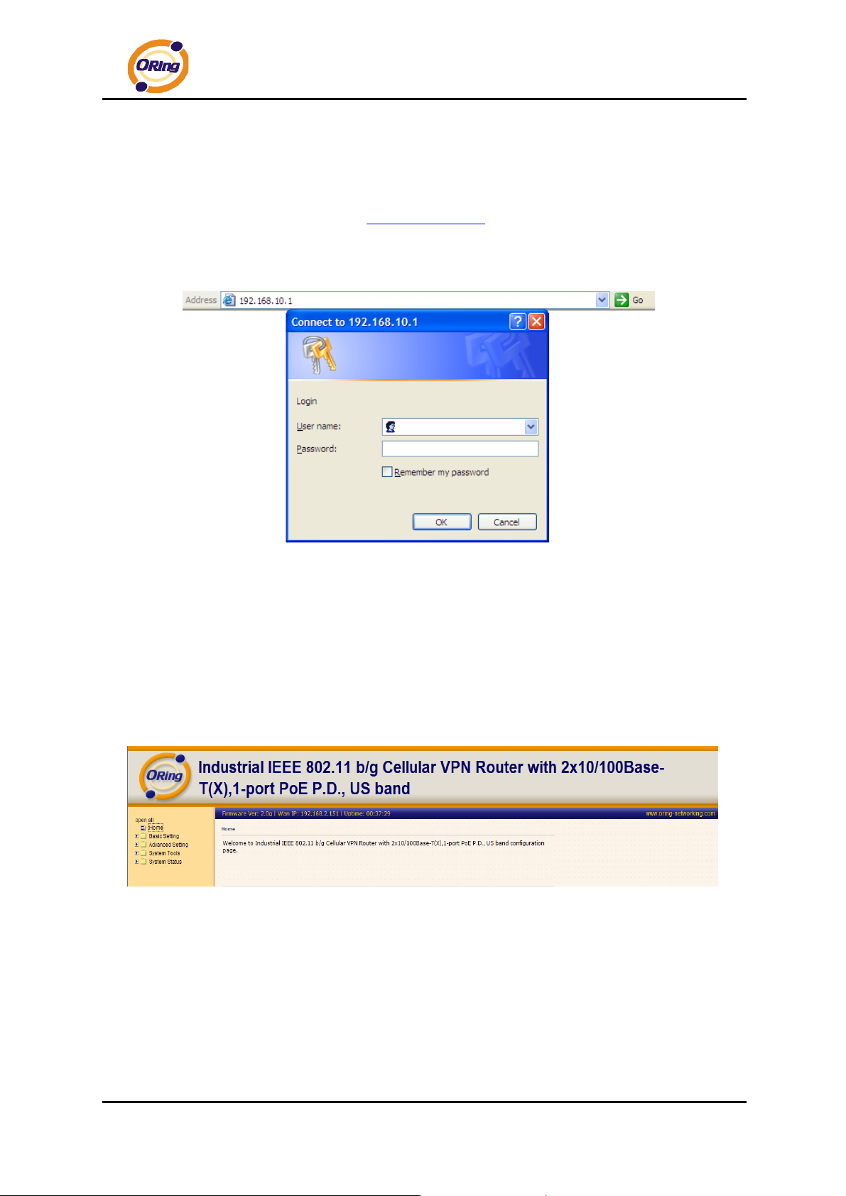
5.2 Configure the Wireless Router
In this section, the web management page will be explained in detail.
By default setting, you can type http://192.168.10.1
to login the web management interface. A login window will be prompted, enter username
admin & password admin to login.
Login screen
For security reasons, we strongly recommend you to change the password. Click on
in the address box of web browser
System Tools > Login Setting and change the password.
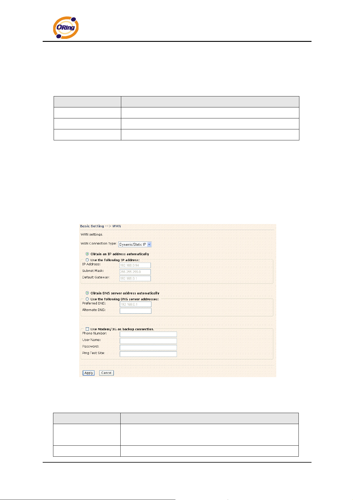
5.3 Main Interface
The Home screen will be shown when login successfully.
Main Interface
ORing Industrial Networking Corp……………………………………………………………….…15
Page 20
IAR-120 / 120+ User’s Manual
In the page, you can check the Firmware version, the router running time and the WAN
IP setting.
The following table describes the labels in this screen.
Label Description
Firmware
Uptime
Wan IP
Show the current firmware version.
Show the elapsed time since the AP router is started.
Show the WAN IP address.
5.3.1 Basic Setting
WAN
The IAR-120 / 120+ AP router provide three types of WAN connection.
1. WAN Connection Type: Dynamic/Static IP
Dynamic/Static IP
The following table describes the labels in this screen.
Label Description
Obtain an IP address
automatically
Use the following IP
ORing Industrial Networking Corp. 16
Select this option if you would like to have an IP address assigned
automatically from the WAN port by DHCP server in your network.
Select this option if you would like to assign an IP address to the
Page 21

IAR-120 / 120+ User’s Manual
address
Obtain DNS server
address
automatically
Use the following
DNS server
addresses
Use Modem/3G as
backup connection
WAN port manually. You should set the IP Address, Subnet Mask
and Default gateway appropriately so that they comply with IP
rules.
Obtain DNS server from DHCP server. If the above Obtain an
IP address automatically is selected, this option will be chosen
accordingly.
Specify DNS server address manually.
Enable this option if you want to use Modem/3G as a backup
connection when normal connection is lost.
Phone Number, User Name and Password: Use these settings
to dial up the Modem/3G connection.
Ping Test Site: Use this site address to check if the connection is
alive or lost. Take www.google.com as an example.
ORing Industrial Networking Corp……………………………………………………………….…17
Page 22
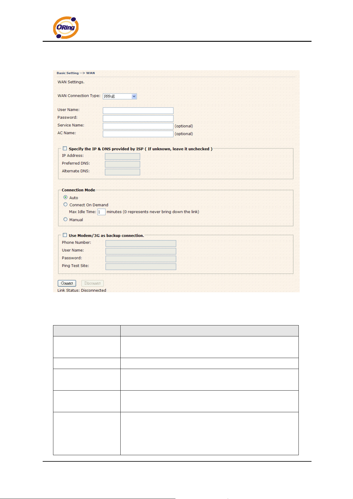
2. WAN Connection Type: PPPoE
IAR-120 / 120+ User’s Manual
PPPoE Screen.
The following table describes the labels in this screen.
Label Description
User Name /
Password
Service Name
Enter the username & password provided by your Internet
Service Provider (ISP).
Enter the service name provided by your ISP.
Enter the name of the access concentrator as provided by your
AC Name
ISP.
Specify the IP & DNS
Enter static IP and DNS address which may required by some ISP
provided by ISP
Auto: Connect automatically when the router boots up.
Connect on Demand: Select to disconnect the PPP session if
Connection Mode
the router has had no traffic for the specified amount of time.
Enter the Max Idle Time in minutes.
ORing Industrial Networking Corp. 18
Page 23
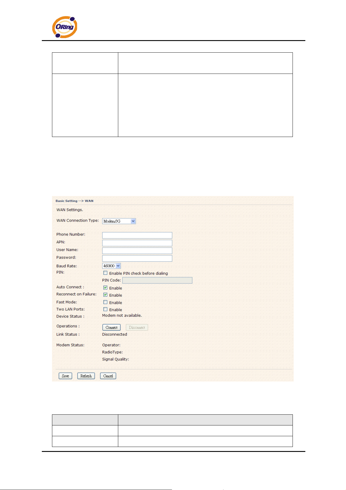
IAR-120 / 120+ User’s Manual
Manual: Select this option to use only the Connect/Disconnect
buttons to call up or close the connection.
Enable this option if you want to use Modem/3G as a backup
connection when PPPoE connection is lost.
Use Modem/3G as
backup connection
Phone Number, User Name and Password: Use these settings
to dial up the Modem/3G connection.
Ping Test Site: Use this site address to check if the connection is
alive or lost. Example is as www.google.com
3. WAN Connection Type: Modem / 3G
For using this type of connection, you need an USB to RS232 converter and a
modem or 3G USB modem (HUAWEI E220 is supported) directly. Please connect the
converter or 3G modem to the USB port before starting the WLAN AP router.
Modem/3G Screen
The following table describes the labels in this screen.
Label Description
Phone Number
APN
Telephone number provided by your ISP.
Enter the APN value it is optional
ORing Industrial Networking Corp……………………………………………………………….…19
Page 24
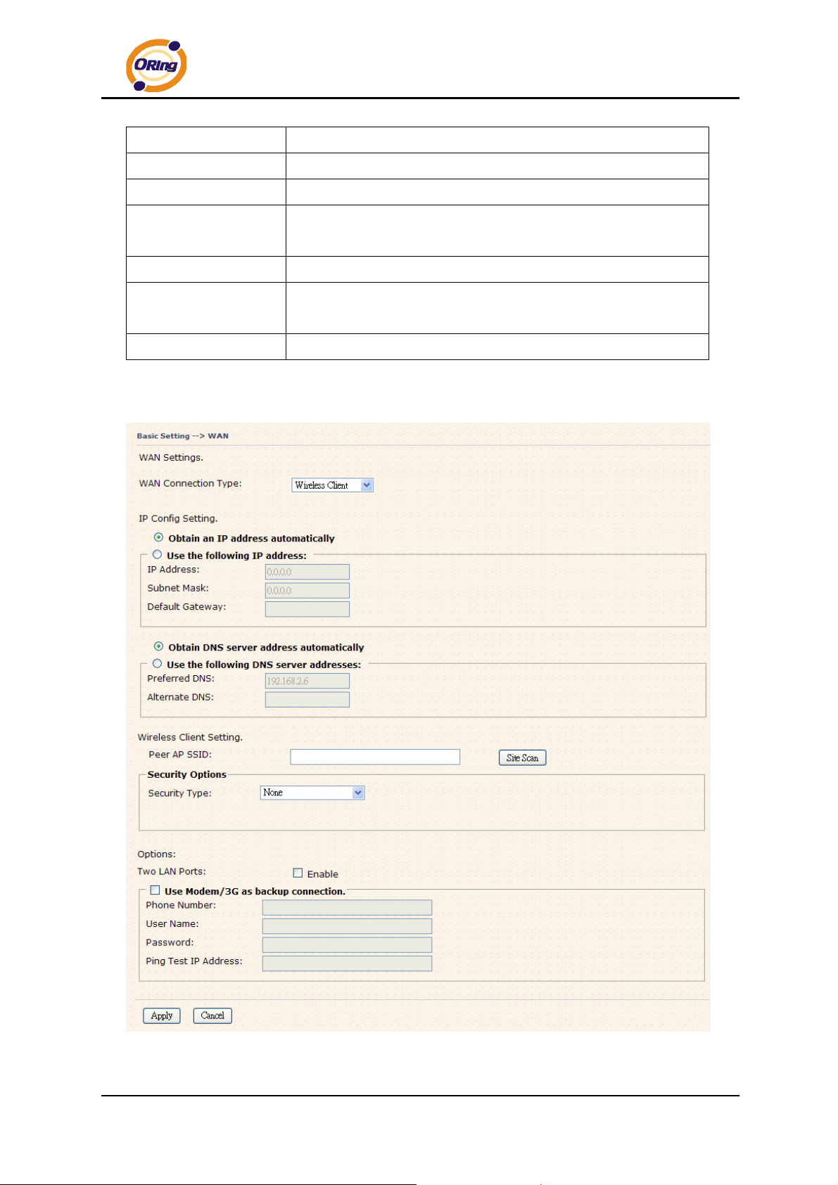
IAR-120 / 120+ User’s Manual
User Name
Password
PIN
Auto Connect
Device Status
Operations
Link Status
User name provided by your ISP.
Password provided by your ISP.
Enter the PIN code if PIN check is required.
If this option is enabled, the connection will be called up when
router boots up.
Show the status of Medem/3G device.
Click “Connect” to call up the Modem/3G. Click "Disconnect" to
shut down the connection.
Show the status of connection, up, down or connecting.
4. WAN Connection Type: Wireless client
Wireless Client on WAN
ORing Industrial Networking Corp. 20
Page 25
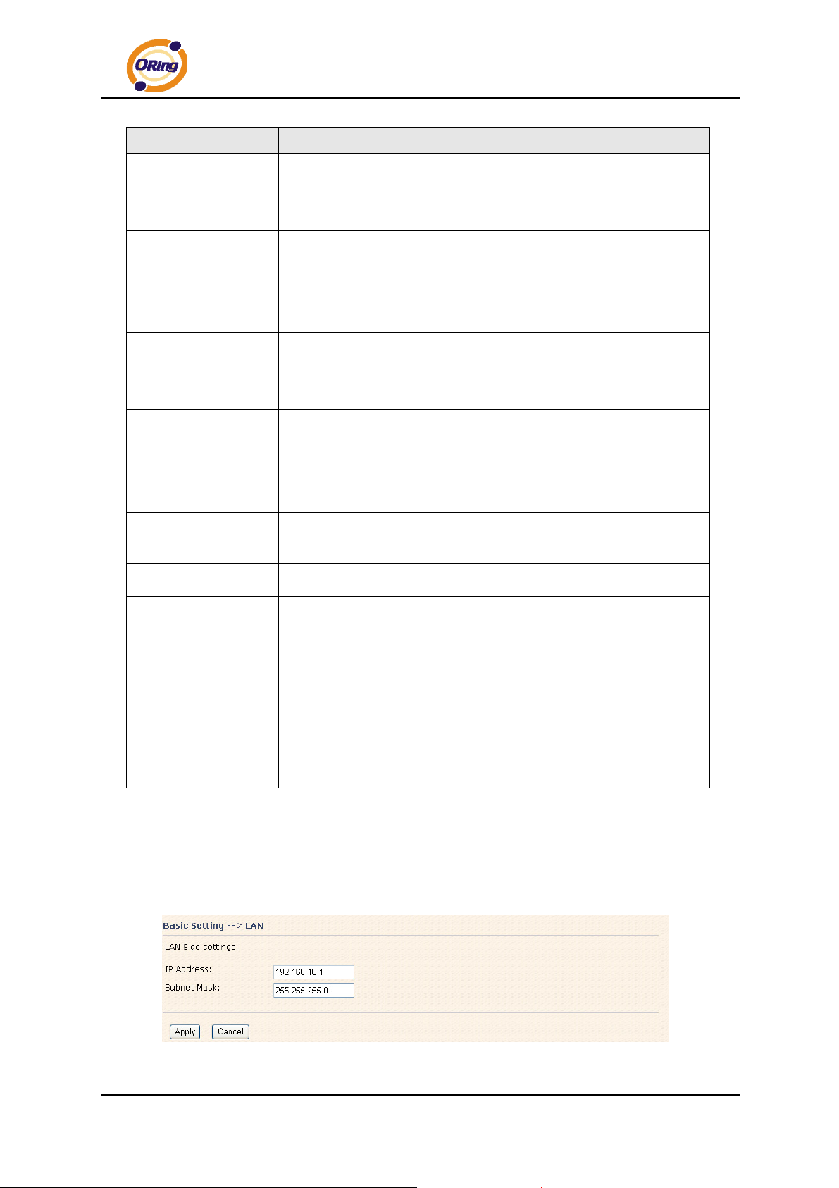
Label Description
IAR-120 / 120+ User’s Manual
Obtain an IP
address
automatically
Use the following IP
address
Obtain DNS server
address
automatically
Use the following
DNS server
addresses
Peer AP SSID
Site Scan
Security Type
Use Modem/3G as
Select this option if you would like to have an IP address assigned
automatically from the WAN port by DHCP server in your network.
Select this option if you would like to assign an IP address to the
WAN port manually. You should set the IP Address, Subnet Mask
and Default gateway appropriately so that they comply with IP
rules.
Obtain DNS server from DHCP server. If the above Obtain an IP
address automatically is selected, this option will be chosen
accordingly.
Specify DNS server address manually.
Enter the other AP or AR SSID which you want to client
You can scan the SSIDs which used for AP mode in the certainty
area
Set the same security with the Client unit which you want to
connect.
Enable this option if you want to use Modem/3G as a backup
backup connection
connection when normal connection is lost.
Phone Number, User Name and Password: Use these settings
to dial up the Modem/3G connection.
Ping Test Site: Use this site address to check if the connection is
alive or lost. Take www.google.com as an example.
LAN
These are the IP settings of the LAN interface for the IAR-120 / 120+ WLAN
AP router. The LAN IP address is privately for your internal network and can not
be exposed on the Internet.
LAN Screen
ORing Industrial Networking Corp……………………………………………………………….…21
Page 26
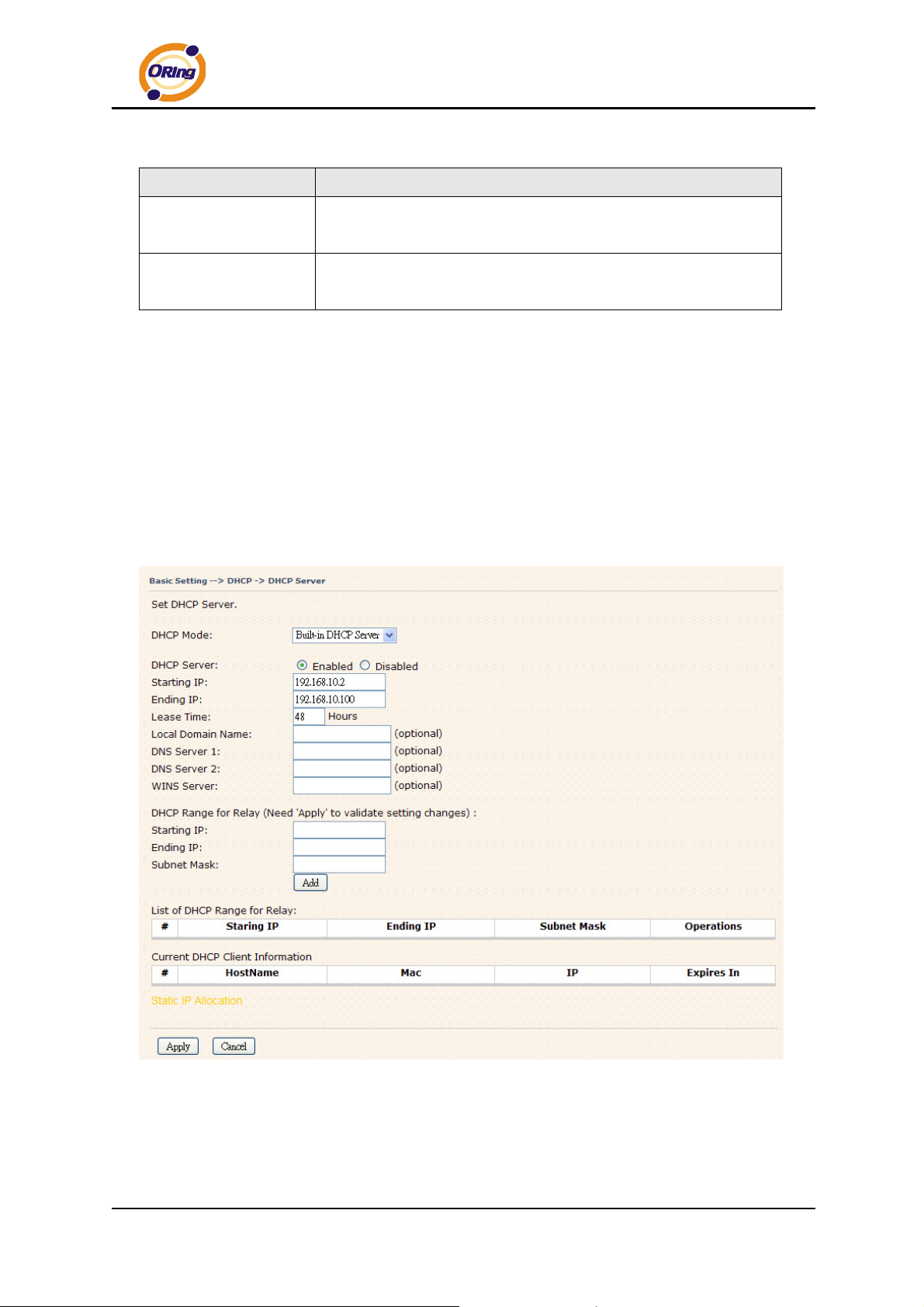
The following table describes the labels in this screen.
Label Description
IAR-120 / 120+ User’s Manual
IP Address
Subnet Mask
The IP address of the LAN interface, the default IP address is
192.168.10.1
The Subnet Mask of the LAN interface, the default Subnet mask
is 255.255.255.0
DHCP
DHCP stands for Dynamic Host Control Protocol. The IAR-120 / 120+ AP router
with a built-in DHCP server. The internal DHCP server will assign an IP address to
the computers (DHCP client) on the LAN automatically.
Set your computers to be DHCP clients by setting their TCP/IP settings to Obtain
an IP Address Automatically. The DHCP server will allocate an unused IP address
from the IP address pool to the requesting computer automatically.
1. DHCP Sever
DHCP Server Screen
ORing Industrial Networking Corp. 22
Page 27
The following table describes the labels in this screen.
Label Description
IAR-120 / 120+ User’s Manual
DHCP Mode
DHCP Server
Starting IP
Ending IP
Lease Time
Local Domain Name
DNS Server 1&2
WINS Server
DHCP Relay start IP
DHCP Relay end IP
Subnet Mask
List of DHCP Range
for relay
Current DHCP Client
Select built-in DHCP server or DHCP Forwarder
Enable or Disable the DHCP Server. The default setting is
Enable
The starting IP address of the IP range for the DHCP server
The ending IP address of the IP range for the DHCP server
The period of time for the IP to be leased. Enter the Lease time.
The default setting is 48 hours.
Enter the local domain name of private network. It is optional.
Enter the DNS Server. It is optional.
Enter the WINS Server. It is optional.
Enter DHCP Relay starting IP
Enter DHCP Relay Ending IP
Enter DHCP Relay IP Subnet mask
List DHCP Relay IP range
List of the computers on your network that are assigned an IP
Information
address by internal DHCP server.
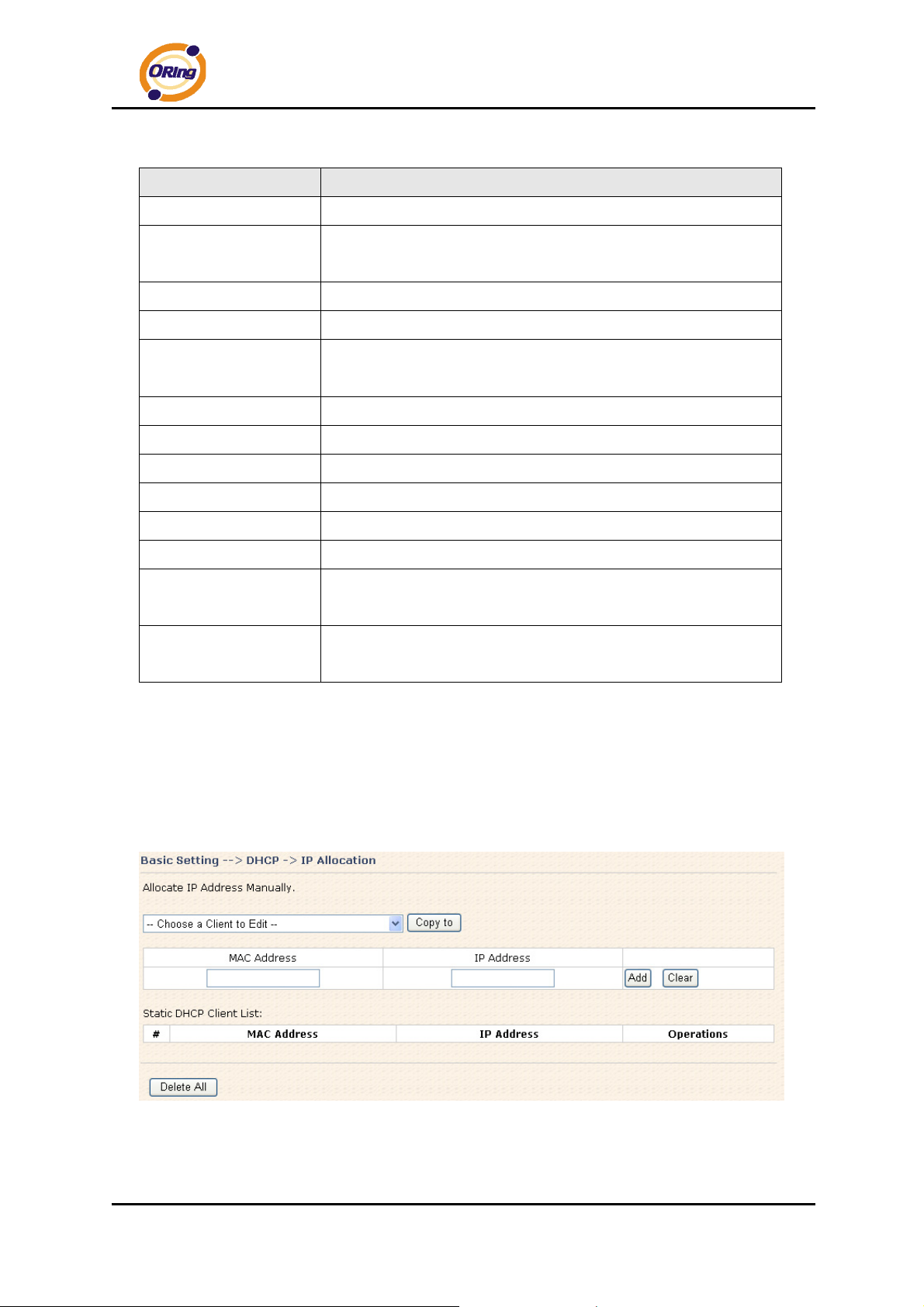
2. IP Allocation
The IP Allocation provides one-to-one mapping of MAC address to IP address.
When a computer with the MAC address requesting an IP from the IAR-120 / 120+ AP
router, it will be assigned with the IP address according to the mapping. You can
choose one from the client lists and add it to the mapping relationship.
IP Allocation Screen
ORing Industrial Networking Corp……………………………………………………………….…23
Page 28
The following table describes the labels in this screen.
Label Description
IAR-120 / 120+ User’s Manual
Choose a Client to
Edit
MAC Address
IP Address
Static DHCP Client
List
Wireless
The list shows the MAC addresses and IP addresses that are
already assigned by IAR-120 / 120+. Choose one from the list
and click Copy to button for editing.
The MAC addresses of the computer.
The IP address to be related to the MAC address.
The list shows the MAC address and IP address one-to-one
relationship.
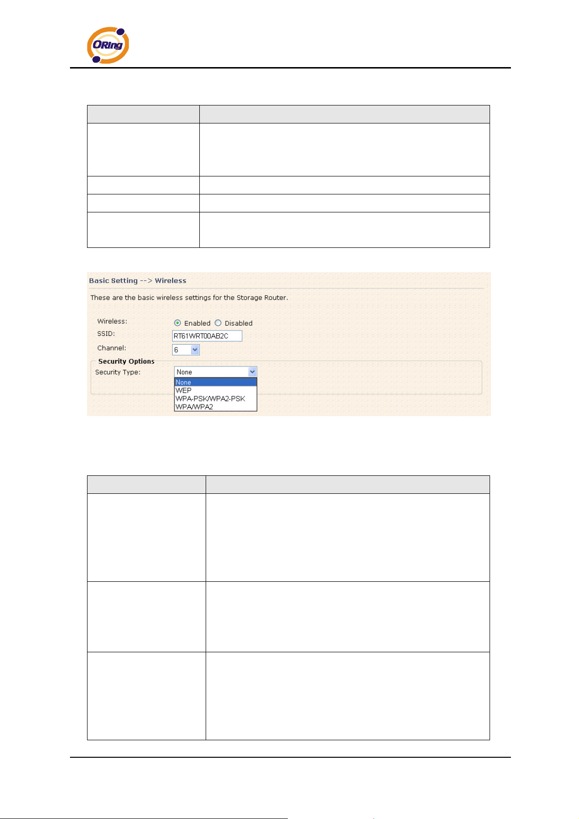
Wireless Screen
The following table describes the labels in this screen.
Label Description
Service Set Identifier (SSID) is a unique name that identifies a
network. All devices on the network must set the same SSID
SSID
name in order to communicate on the network. If you change
the SSID from the default setting, input your new SSID name in
this field.
Channel 6 is the default channel. All devices on the network
must share the same channel.*
Channel
*Note: The wireless devices will automatically scan and match the
wireless setting of the AP router with the same SSID.
Select the type of security for WLAN connection:
None: disable encryption.
Security options
WEP: Wired Equivalent Privacy (WEP) is a wireless security
protocol for WLAN. WEP provides data encryption for
communicating over the WLAN.
ORing Industrial Networking Corp. 24
Page 29
IAR-120 / 120+ User’s Manual
WPA-PSK/WPA2-PSK: WPA-PSK or WPA2-PSK with a
pre-shared key,
pass phrase.
WPA/WPA2: Wi-Fi Protected Access (WPA) authentication in
conjunction with a RADIUS server.
Security Type – None
No security protection for WLAN.
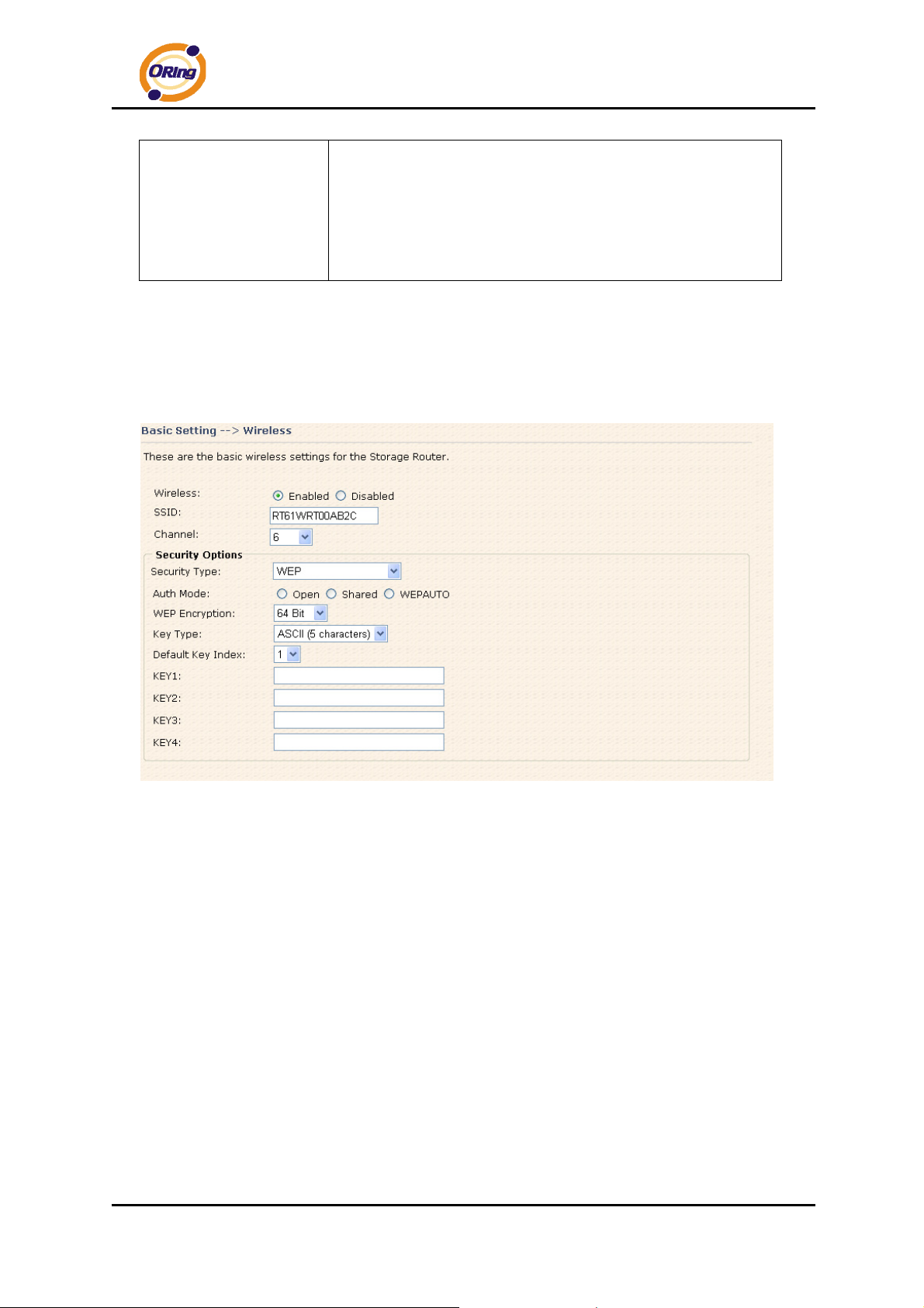
Security Type – WEP
each authorized computer is given the same
Wireless Security Type-WEP Screen
1. Choose one of three Auth Modes: Open, Share and WEPAUTO
2. WEP Encryption: Select 64 Bit or 128 Bit WEP encryption.
3. Key Type: Select ASCII or Hex key type.
4. Default Key Index: Select one of the keys to be the active key.
5. Key 1-4: Input up to four encryption keys.
ASCII (American Standard Code for Information Interchange) is a code for
representing English letters as numbers from 0-127. Hex digits consist of the numbers
0-9 and the letters A-F.
ORing Industrial Networking Corp……………………………………………………………….…25
Page 30
IAR-120 / 120+ User’s Manual
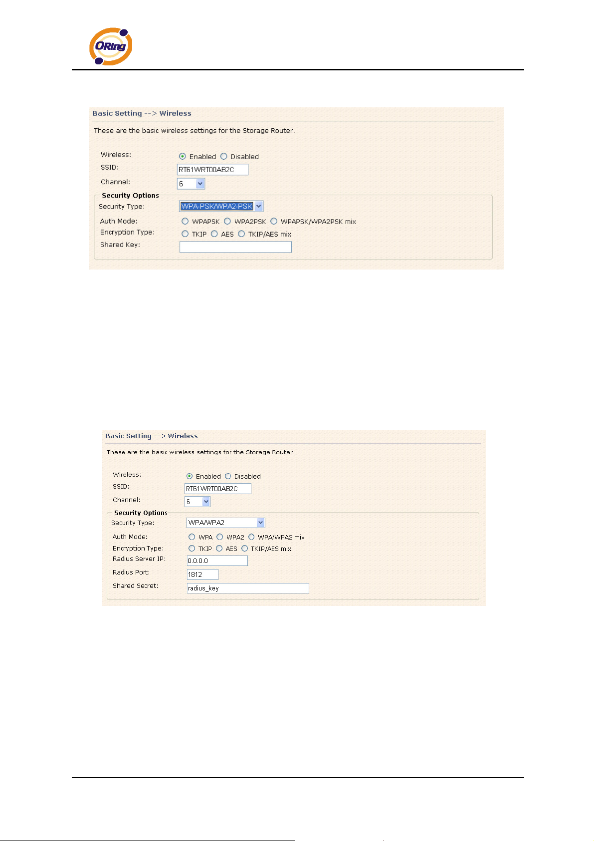
Security Type – WPA-PSK/WPA2-PSK
Wireless Security Type-WPA-PSK/WPA2-PSK Screen
1. Security Type: Select WPA-PSK/WPA2-PSK.
2. Choose one of three Auth Modes: WPAPSK, WPA2PSK, WPAPSK/WPA2PSK
mix
3. Encryption Type: Select TKIP or AES or TKIP/AES mix.
4. Share Key: Enter your pass phase. The pass phase should be between 8 and 64
characters.
Security Type – WPA /WPA2
Wireless Security Type-WPA/WPA2 Screen
1. Security Type: Select WPA/WPA2
2. Auth Mode: Choose one of three Auth Modes: WPA, WPA2, WPA/WPA2 mix.
3. Encryption Type: Choose one of three Encryption Types: TKIP, AES, TKIP/AES
mix.
4. Radius Server IP: Enter the IP address of the RADIUS Server.
5. Port: Enter the RADIUS port (1812 is default).
6. Shared Secret: Enter the RADIUS password or key.
ORing Industrial Networking Corp. 26
Page 31
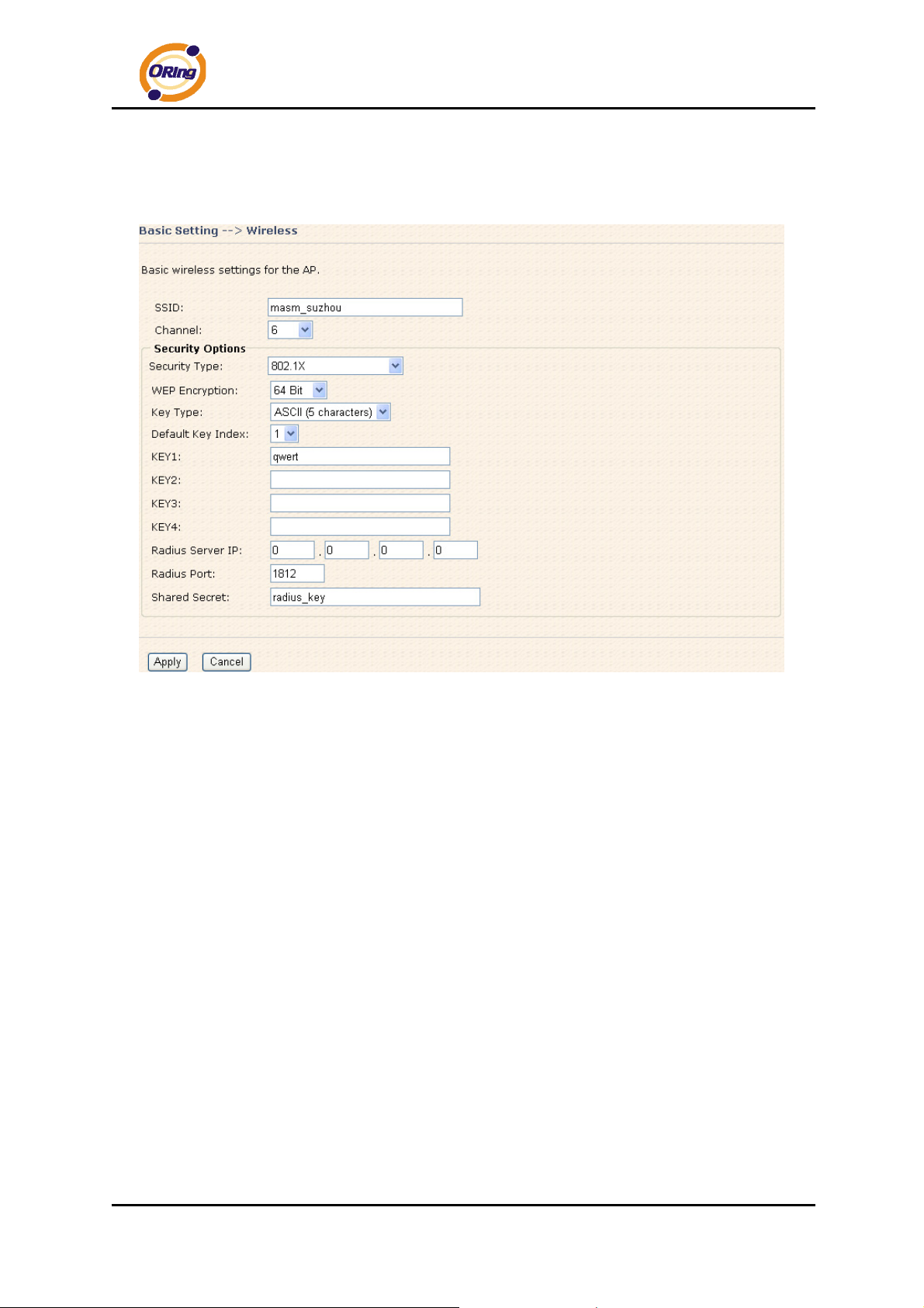
Security Type – 802.1X
IAR-120 / 120+ User’s Manual
1. Security Type: Select 802.1X
2. WEP Encryption: Select 64 Bit or 128 Bit WEP encryption.
3. Key Type: Select ASCII or Hex key type.
4. Default Key Index: Select one of the keys to be the active key.
5. Key 1-4: Input up to four encryption keys.
6. Radius Server IP: Enter the IP address of the RADIUS Server.
7. Port: Enter the RADIUS port (1812 is default).
8. Shared Secret: Enter the RADIUS password or key.
RADIUS, or Remote Authentication Dial-In User Service, is a widely deployed
protocol that enables companies to authenticate, authorize and account for remote
users who want access to a system or service from a central network server.
Radius server validates your proof, also carry on the authorization. So the Radius
server received by ISA server responded (point out the customer carries proof to be not
granted) and it means that the Radius server did not authorize you to carry. Even if
the proof has already passed an identify verification, the ISA server may also refuse
ORing Industrial Networking Corp……………………………………………………………….…27
Page 32
IAR-120 / 120+ User’s Manual
you to carry a claim according to the authorization strategy of the Radius server.
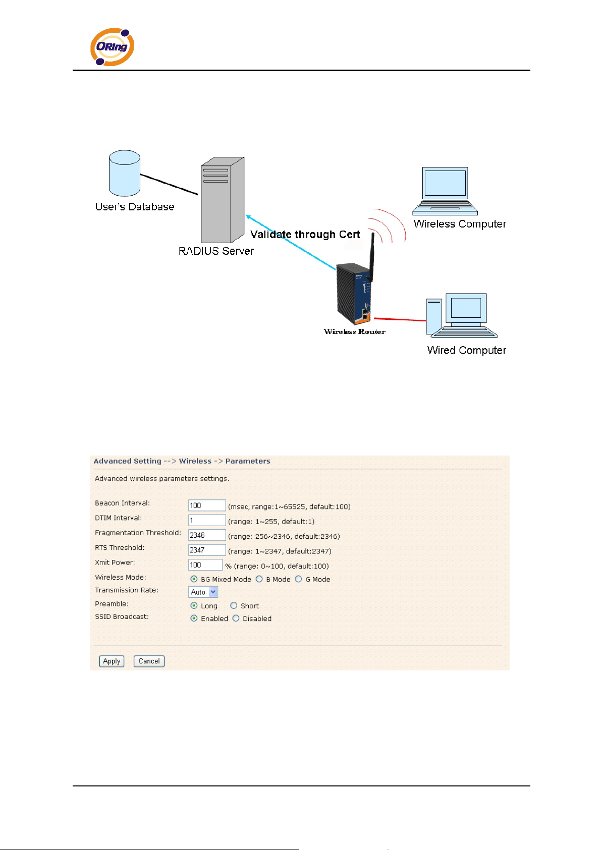
The principle of the Radius server is shown in the following pictures:
5.3.2 Advanced Setting
Wireless
1. Parameters
Parameters Screen
ORing Industrial Networking Corp. 28
Page 33

The following table describes the labels in this screen.
Label Description
The default value is 100. The Beacon Interval value indicates
IAR-120 / 120+ User’s Manual
Beacon Interval
DTIM Interval
Fragmentation
Threshold
the frequency interval of the beacon. A beacon is a packet
broadcast by the AP to synchronize the wireless network. 50 is
recommended in poor connection.
The default value is 1. This value, between 1 and 255
milliseconds, indicates the interval of the Delivery Traffic
Indication Message (DTIM). A DTIM field is a countdown field
informing clients of the next window for listening to broadcast and
multicast messages. When the AP has buffered broadcast or
multicast messages for associated clients, it sends the next DTIM
with a DTIM Interval value. Its clients hear the beacons and
awaken to receive the broadcast and multicast messages.
This value should remain at its default setting of 2346. The
range is 256-2346 bytes. It specifies the maximum size for a
packet before data is fragmented into multiple packets. If you
experience a high packet error rate, you may slightly increase the
Fragmentation Threshold. Setting the Fragmentation Threshold
too low may result in poor network performance. Only minor
RTS Threshold
Xmit Power
Wireless Network
Mode
modifications of this value are recommended.
This value should remain at its default setting of 2347. The
range is 0-2347 bytes. Should you encounter inconsistent data
flow, only minor modifications are recommended. If a network
packet is smaller than the preset RTS threshold size, the
RTS/CTS mechanism will not be enabled. The AP sends
Request to Send (RTS) frames to a particular receiving station
and negotiates the sending of a data frame. After receiving an
RTS, the wireless station responds with a Clear to Send (CTS)
frame to acknowledge the right to begin transmission.
Control RF transmission power, this value ranges from 1 - 100
percent, default value is 100 percent.
If you have IEEE802.11g and IEEE802.11b devices in your
network, then keep the default setting, BG Mixed mode. If you
have only IEEE802.11g devices, select G Mode. If you would
like to limit your network to only IEEE802.11b devices, then
select B Mode.
ORing Industrial Networking Corp……………………………………………………………….…29
Page 34

IAR-120 / 120+ User’s Manual
The default setting is Auto. The range is from 1 to 54Mbps.
The rate of data transmission should be set depending on the
speed of your wireless network. You can select from a range of
Transmission Rate
transmission speeds, or keep the default setting, Auto, to have
the AP automatically use the fastest possible data rate and
enable the Auto-Fallback feature. Auto-Fallback will negotiate
the best and possible connection speed between the AP and a
wireless client.
Values are Long and Short, default value is Long. If your
wireless device supports the short preamble and you are having
Preamble
trouble getting it to communicate with other IEEE802.11b
devices, make sure that it is set to use the long preamble
When wireless clients survey the local area for wireless networks
to associate with, they will detect the SSID broadcast by the AP.
SSID Broadcast
To broadcast the AP SSID, keep the default setting, Enable. If
you do not want to broadcast the AP SSID, then select Disable.
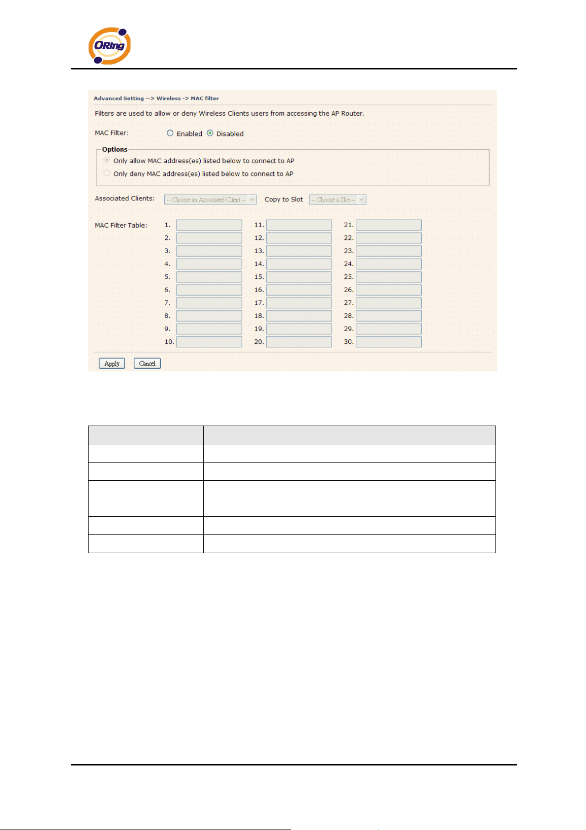
2. MAC Filter
Use MAC Filter to allow or deny wireless clients to associate with IAR-120 / 120+ AP
router. You can manually add a MAC address or select the MAC address from
Associated Clients that are currently associated with IAR-120 / 120+.
ORing Industrial Networking Corp. 30
Page 35
IAR-120 / 120+ User’s Manual
MAC Filter Screen
The following table describes the labels in this screen.
Label Description
MAC Filter
MAC Filter List
Connected Clients
MAC Address
Apply
Enable or disable the function of MAC filter.
This list shows the MAC addresses that are in the selected filter.
This list shows the wireless MAC addresses that associated with
AP.
MAC addresses for editing.
Click Apply to activate the configurations.
NAT Setting
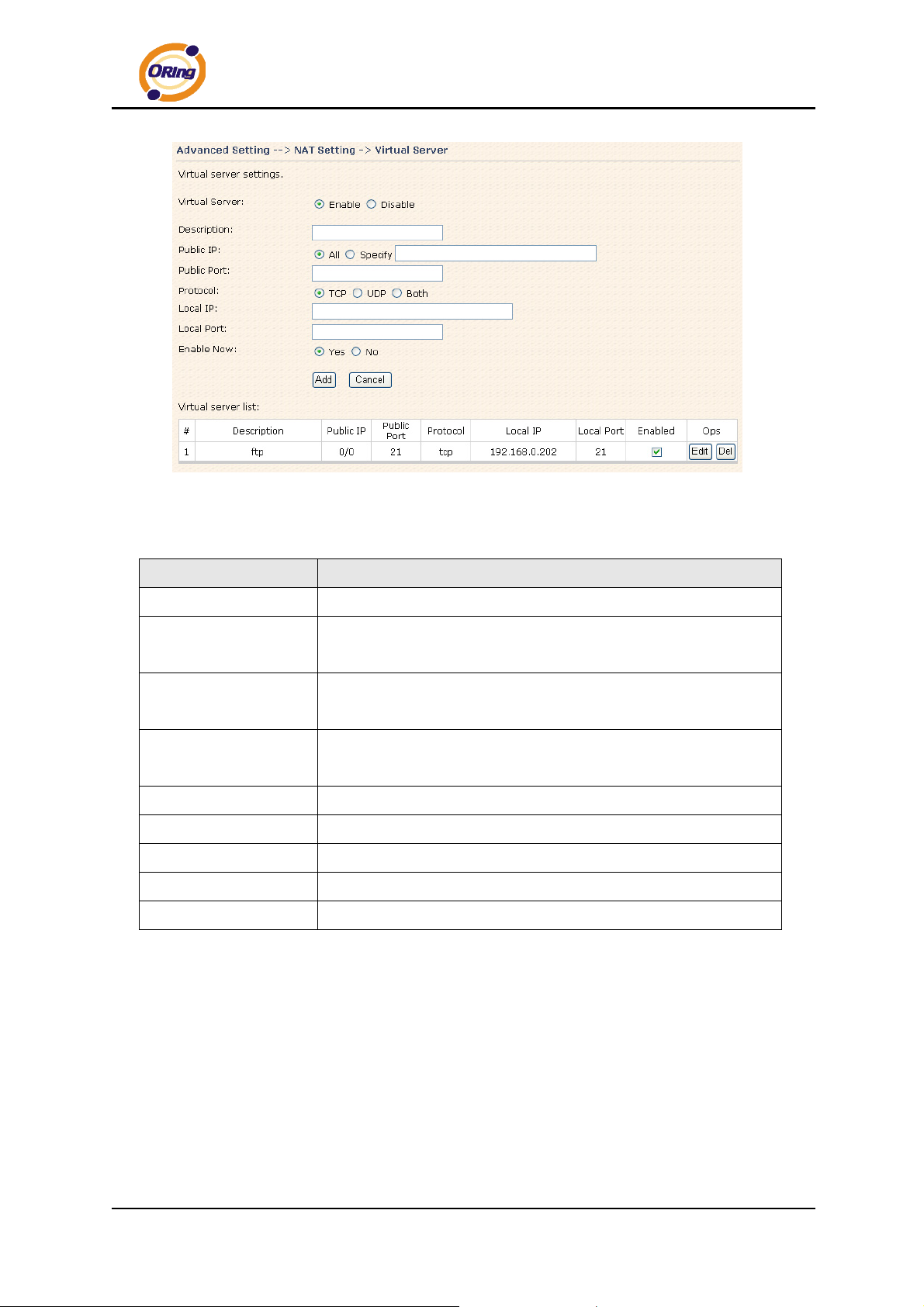
1. Virtual Server
Virtual Server is used for setting up public services on the LAN, such as DNS, FTP and
Email. Virtual Server is defined as a Local Port to the LAN servers, and all requests
from Internet to this Local port will be redirected to the computer specified by the Local IP.
Any PC that was used for a virtual server must have static or reserved IP Address
because its IP address may change when requesting IP by DHCP.
ORing Industrial Networking Corp……………………………………………………………….…31
Page 36
Virtual Server
IAR-120 / 120+ User’s Manual
The following table describes the labels in this screen.
Label Description
Virtual Server
Description
Enable or disable Virtual Server.
Enter the description of the entry. Acceptable characters consist
of '0-9', 'a-z', 'A-Z'. This field accepts null value.
Public IP
Enter the public IP that is allowed to access the virtual service, if
not specified, choose All.
Public Port
The port number on the WAN (Wide Area Network) side that will
be used to access the virtual service.
Protocol
Local IP
Local Port
Enable Now
Virtual server list
The protocol used for the virtual service.
The IP of the computer that will be providing the virtual service.
The port number of the service used by the Private IP computer.
Enable the virtual server entry after adding it.
Click Edit to edit the virtual service entry, Del to delete the entry.
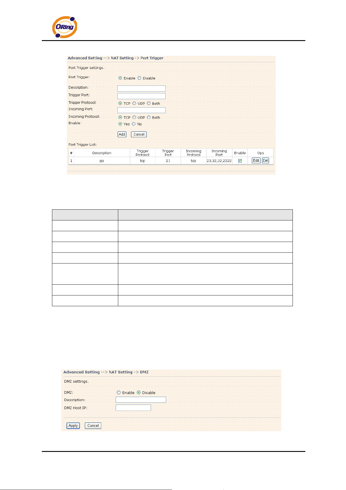
2 Port Trigger
Some applications require multiple connections, like Internet games, video conferencing,
Internet calling and so on. These applications cannot work with a pure NAT router. Port
Trigger is used for some of the applications that can work with an NAT router.
ORing Industrial Networking Corp. 32
Page 37
IAR-120 / 120+ User’s Manual
Port Trigger Screen
The following table describes the labels in this screen.
Label Description
Port Trigger
Description
Trigger Port
Trigger Protocol
Incoming Port
Enable or disable Port Trigger.
This is the description for the entry.
This is the port used to trigger the application.
This is the protocol used to trigger the application.
This is the port number on the WAN side that will be used to
access the application.
Enable
Port Trigger List
Enable the rule after adding the entry.
Click Edit to edit the entry, click Del to delete the entry.
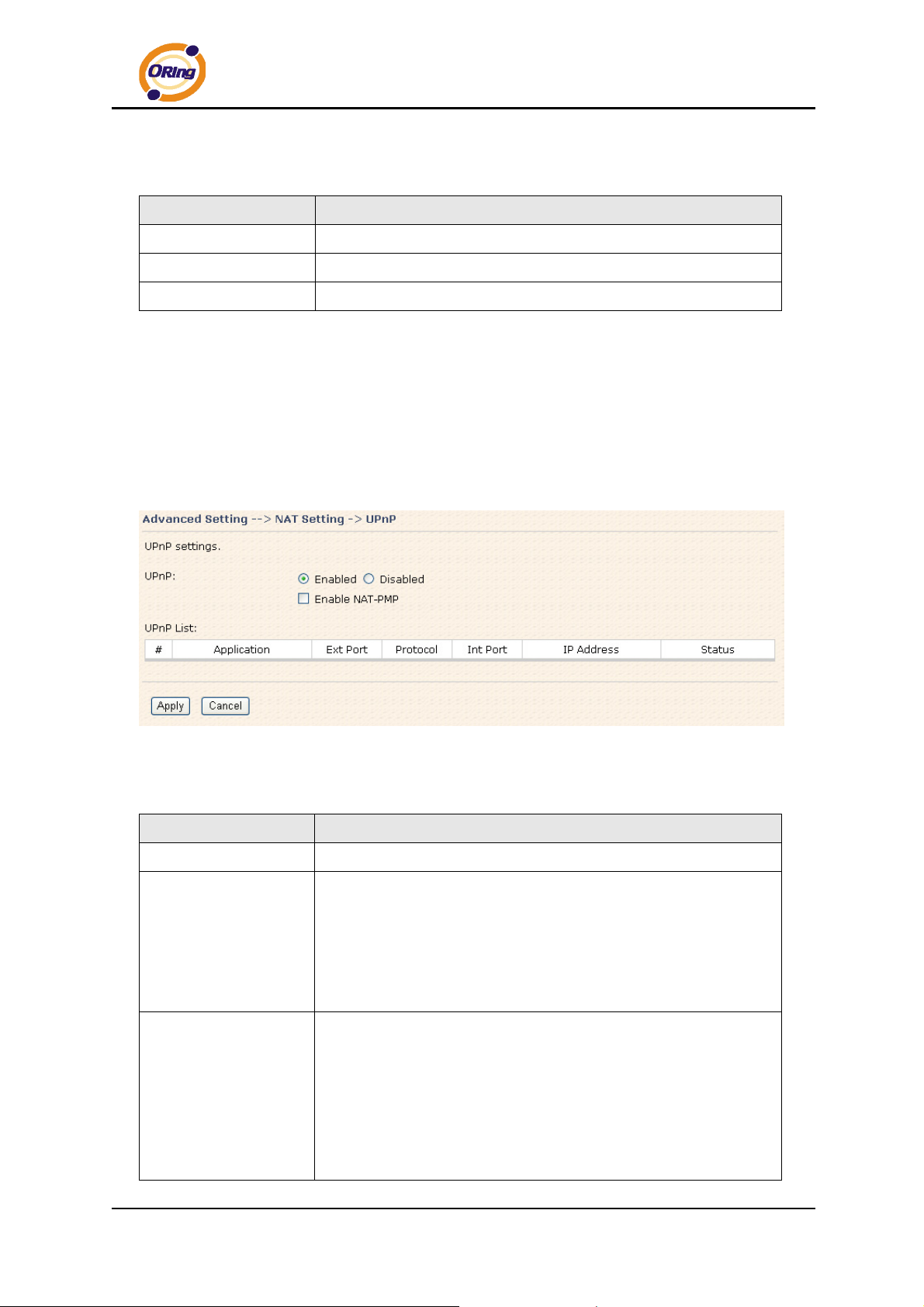
3. DMZ
It allows a computer to be exposed to the Internet. This feature is useful for gaming
purposes.
Enter the IP address of the internal computer that will be the DMZ host. Adding a
client to the DMZ may expose your local network with variety of security risks, so only
use this option carefully.
DMZ Screen
ORing Industrial Networking Corp……………………………………………………………….…33
Page 38
The following table describes the labels in this screen.
Label Description
IAR-120 / 120+ User’s Manual
DMZ
Description
DMZ Host IP
Enable or disable the DMZ.
Description for the DMZ host entry.
Enter the IP address of the computer to be in the DMZ.
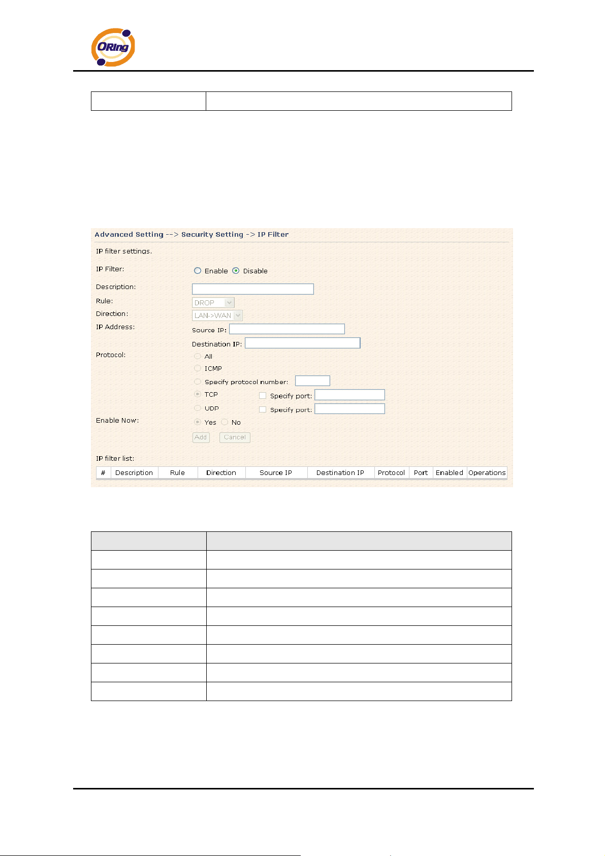
4. UPnP
The UPnP (Universal Plug and Play) feature allows the devices, such as Internet
computers, to access the local host resources or devices as needed. UPnP devices can
be automatically discovered by the UPnP service application on the LAN.
UPnP Screen
The following table describes the labels in this screen.
Label Description
UPnP
Enable NAT-PMP
Enable or disable UPnP.
NAT-PMP allows a computer in a private network (behind a NAT
router) to automatically configure the router to allow parties
outside the private network to contact with each other. NAT-PMP
operates with UDP. It essentially automates the process of port
forwarding. Check the box to enable NAT-PMP.
UPnP List
This table lists the current auto port forwarding information.
Application: The application that generates this port forwarding.
Ext Port: The port opened on WAN side.
Protocol: The protocol type.
Int Port: The port redirected to the local computer.
IP Address: The IP address of local computer to be redirected to.
ORing Industrial Networking Corp. 34
Page 39
IAR-120 / 120+ User’s Manual
Status: This status shows if the entry is valid or not.
Security Setting
1. IP Filter
Filters are used to deny or allow LAN computers from accessing the internet. It also
allow or deny WAN hosts to access LAN computers.
IP Filter Screen
The following table describes the labels in this screen.
Label Description
IP Filter
Description
Rule
Direction
IP Address
Protocol
Enable Now
IP filter list
Enable or disable the IP Filter.
Enter description for the entry.
Select DROP, ACCEPT and REJECT rule for the entry.
Specify the direction of the data flow that is to be filtered.
Enter the IP address of the source and destination computer.
Choose which protocol to be filtered.
Enable the entry after adding it.
Click edit for editing the entry, click Del to delete the entry.
ORing Industrial Networking Corp……………………………………………………………….…35
Page 40
IAR-120 / 120+ User’s Manual
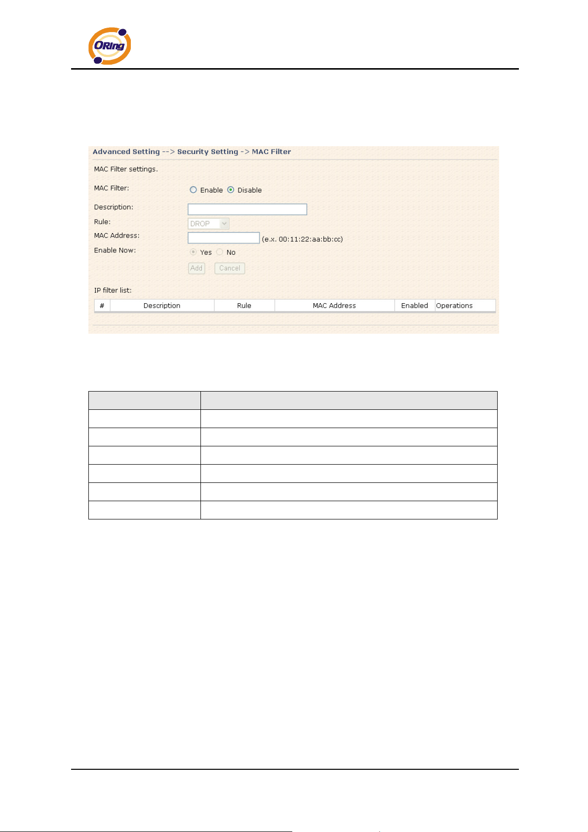
2. MAC Filter
Filters are used to deny or allow LAN computers from accessing the internet, according to
their MAC address.
MAC Filter Screen
The following table describes the labels in this screen.
Label Description
MAC Filter
Description
Rule
MAC Address
Enable Now
IP filter list
Enable or disable the MAC Filter.
Enter the description for the entry.
Select DROP, ACCEPT and REJECT rule for the entry.
Enter the MAC address to be filtered.
Enable the entry after adding it.
Click Edit for editing the entry, click Del to delete the entry.
VPN Setting
VPN Setting is settings that are used to create virtual private tunnels to remote VPN
gateways. The tunnel technology supports data confidentiality, data origin,
authentication and data integrity of network information by utilizing encapsulation
protocols, encryption algorithms, and hashing algorithms.
1. Open VPN
Open VPN is a full-functioned SSL VPN solution which can accommodates a wide
range of configurations including remote access, site-to-site VPNs, WiFi security, and
enterprise-scale remote access solutions with load balancing, failover, and fine-grained
access-controls.
ORing Industrial Networking Corp. 36
Page 41
IAR-120 / 120+ User’s Manual
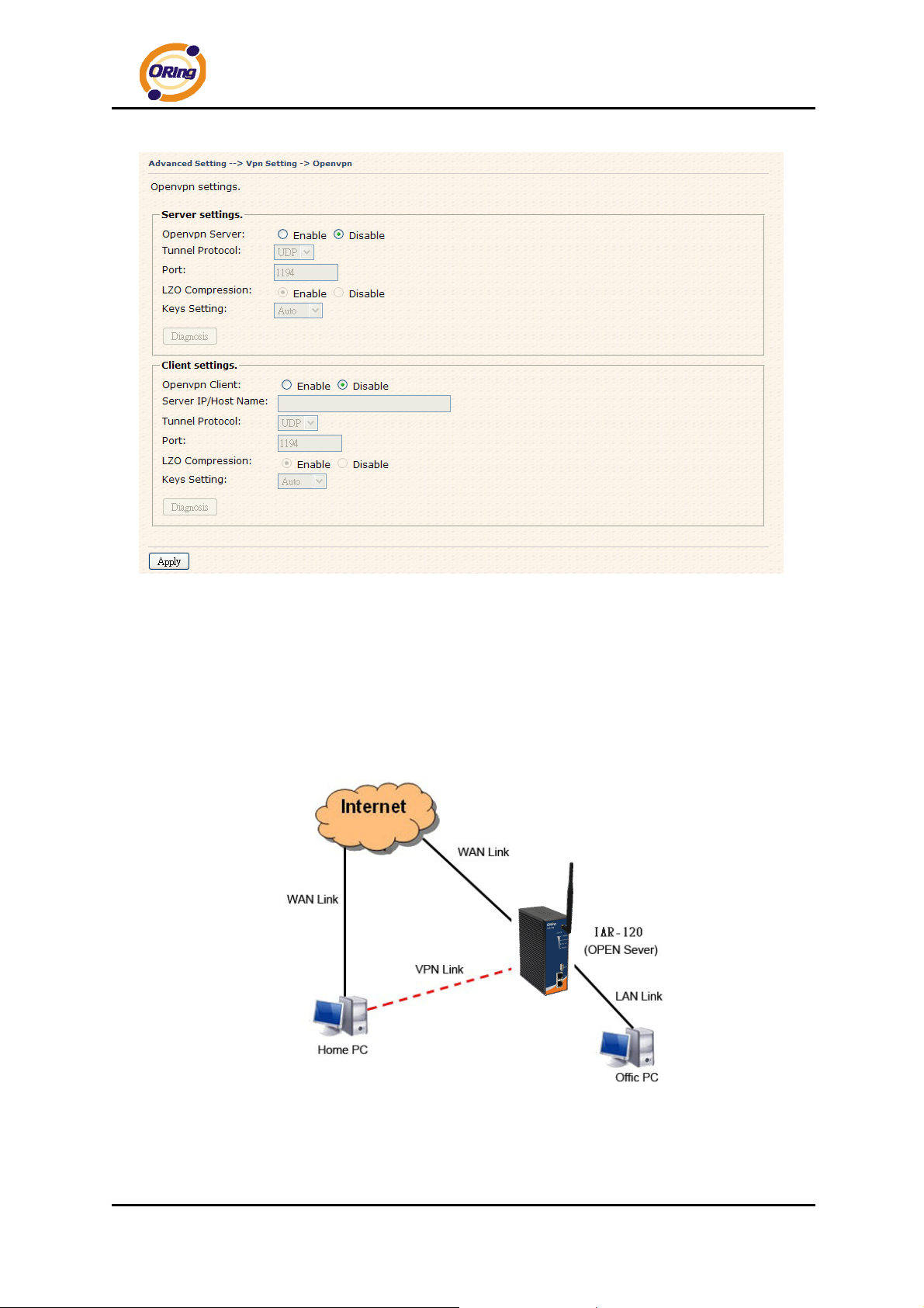
Open VPN Screen
The following topology shows the common use of VPN connection from WAN side.
1: Open VPN Server
Connection to Open VPN Server
ORing Industrial Networking Corp……………………………………………………………….…37
Page 42
IAR-120 / 120+ User’s Manual
Before connecting to the Openvpn server of IAR-120 / 120+ AP routuer, please install
openvpn client software for your windows PC. It can be downloading from
http://openvpn.net/download.html#stablel
. The current version of Openvpn used in
IAR-120 / 120+ is version 2.0.9. The corresponding software for client should be
installed.
The following table describes the labels in this screen.
Label
Open VPN Server
Tunnel Protocol
Port
LZO Compression
Keys Setting
Description
Enable or disable the function of Open VPN Server.
Select UDP or TCP protocol.
Input the number about the port, and the default is 1194.
Enable or disable the function of LZO Compression.
Select Auto to use the preset certificates, select Manual to paste
your certificates. Please install openvpn client software to
generate your certificates and paste them here. For more
information, please visit openvpn website.
2: Open VPN Client
Two routers are needed for creating site-to-site VPN connection using this mode.
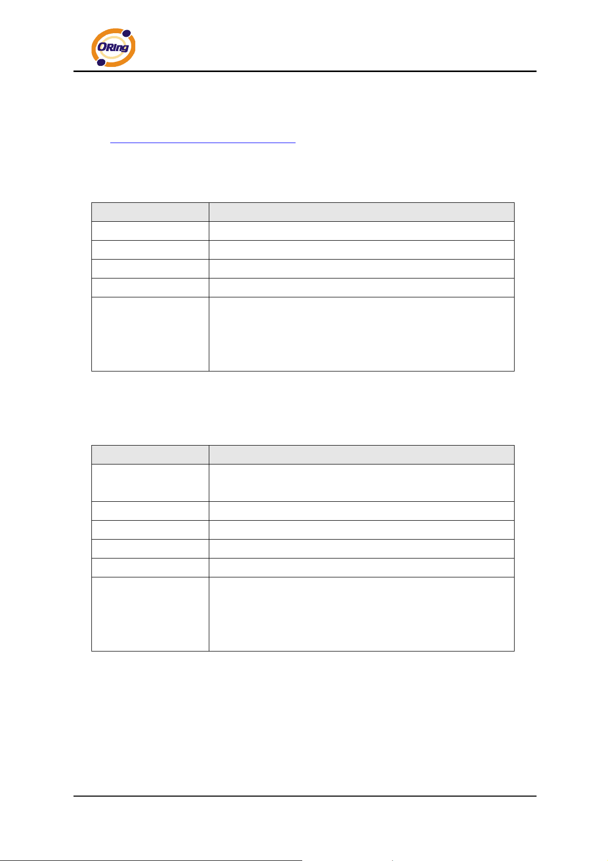
The following table describes the labels in this screen.
Label
Open VPN Client
Description
Enable or disable the function of Open VPN Client. You can
allow or deny the Open VPN Client with this option.
Server IP
Tunnel Protocol
Port
LZO Compression
Keys Setting
Enter the Open VPN Server IP address.
Select UDP or TCP protocol.
Enter the port number, default is 1194.
Enable or disable the LZO Compression.
Select Auto to use the preset certificates, select Manual to paste
your certificates. Please install software for openvpn client to
generate your certificates and paste them here. For more
information, please visit openvpn website.
ORing Industrial Networking Corp. 38
Page 43
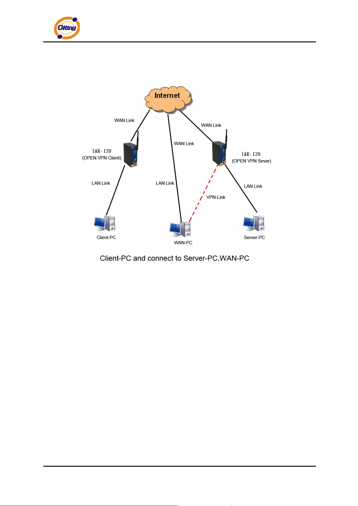
3: Open VPN Server VS Client
IAR-120 / 120+ User’s Manual
The chart above displays the connection of Open VPN Server and Client. The Server
IP and Client IP address should configure with the same network domain.
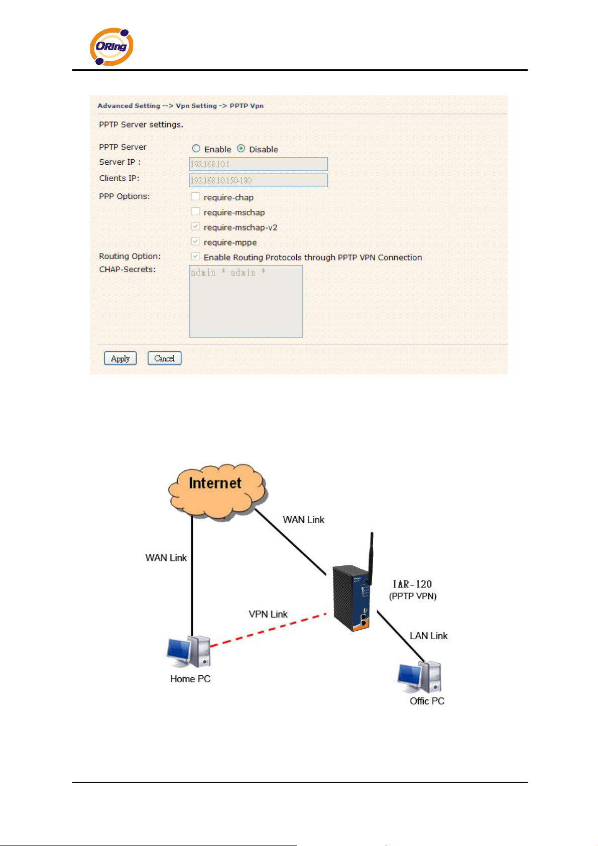
2. PPTP VPN
The PPTP (Point to Point Tunneling Protocol) VPN feature allows PC connected to the
router from WAN port, just like connecting in the LAN.
To create a PPTP connection to the router, you should create a PPTP network
connection if you are using a window PC. The steps are: Right click Network >
property > create a new connection > connect to my work space (VPN) > use VPN
to internet > enter the user name and password which are set in the page.
ORing Industrial Networking Corp……………………………………………………………….…39
Page 44
IAR-120 / 120+ User’s Manual
PPTP VPN Screen
The following topology shows the common use of PPTP connection from the internet.
Connection to PPTP VPN Server
ORing Industrial Networking Corp. 40
Page 45
The following table describes the labels in this screen.
IAR-120 / 120+ User’s Manual
Label
PPTP Server
Server IP
Client IP
Description
Enable or disable PPTP VPN Server.
Enter the server side IP address, default is the LAN port IP.
Enter the IP address range, format is as 192.168.10.xx-xx,
connected client will be assigned the IP address.
CHAP-Secrets
Enter the username and password pairs, format is as user * pass
*, multiple username password pairs are allowed.
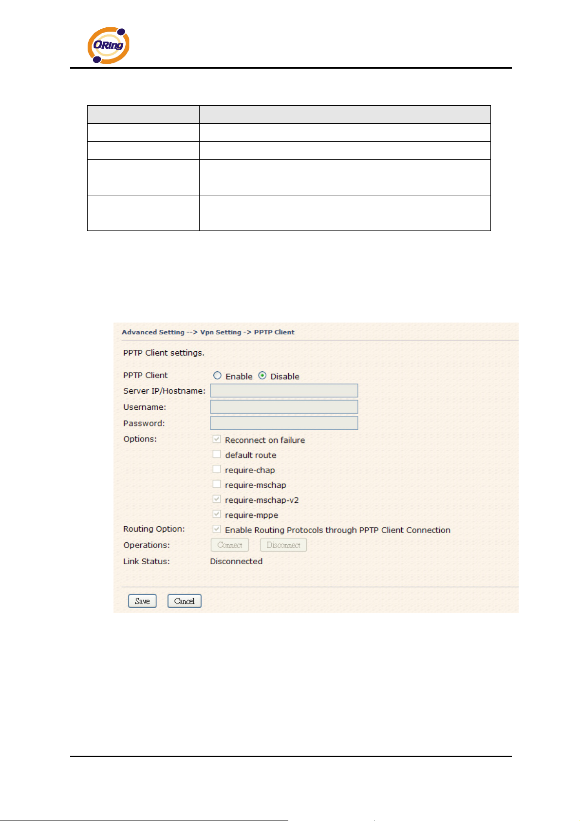
3. PPTP Client
If the router A want to link with the others which is not in the same network with the router
A, the function of PPTP client should support in the router page.
ORing Industrial Networking Corp……………………………………………………………….…41
Page 46
Internet (WAN)
r
IAR-120 / 120+ User’s Manual
Wireless Router
Select: PPTP Client
LAN Line
-
Label
PPTP Client
WAN Line
WAN Line
PPTP VPN Line
WAN Line
PPTP VPN
LAN Line
-
Result: Client-PC can connect to Server-PC, WAN-PC.
Description
Enable or disable PPTP Client.
Wireless Router
Select: PPTP VPN Seve
-
Server
IP/Hostname
Username/Pass
word
Option
Operations
Link Status
Enter the server IP address or hostname.
Enter the username and password which is signed by PPTP server.
Reconnect on failure: Pitch on this option, it will be reconnect when
the link is on failure.
Require MPPE: Choose Enable Require MPPE (Microsoft
Point-to-Point Encryption) to encrypt data across Point-to-Point Protocol
(PPP) and Virtual Private Network links.
Click “Connect” to link the server, if or not, you can click “”Disconnect” to
break off from the server.
Show the status about the link.
ORing Industrial Networking Corp. 42
Page 47
IAR-120 / 120+ User’s Manual
Routing Protocol (Routing Setting)
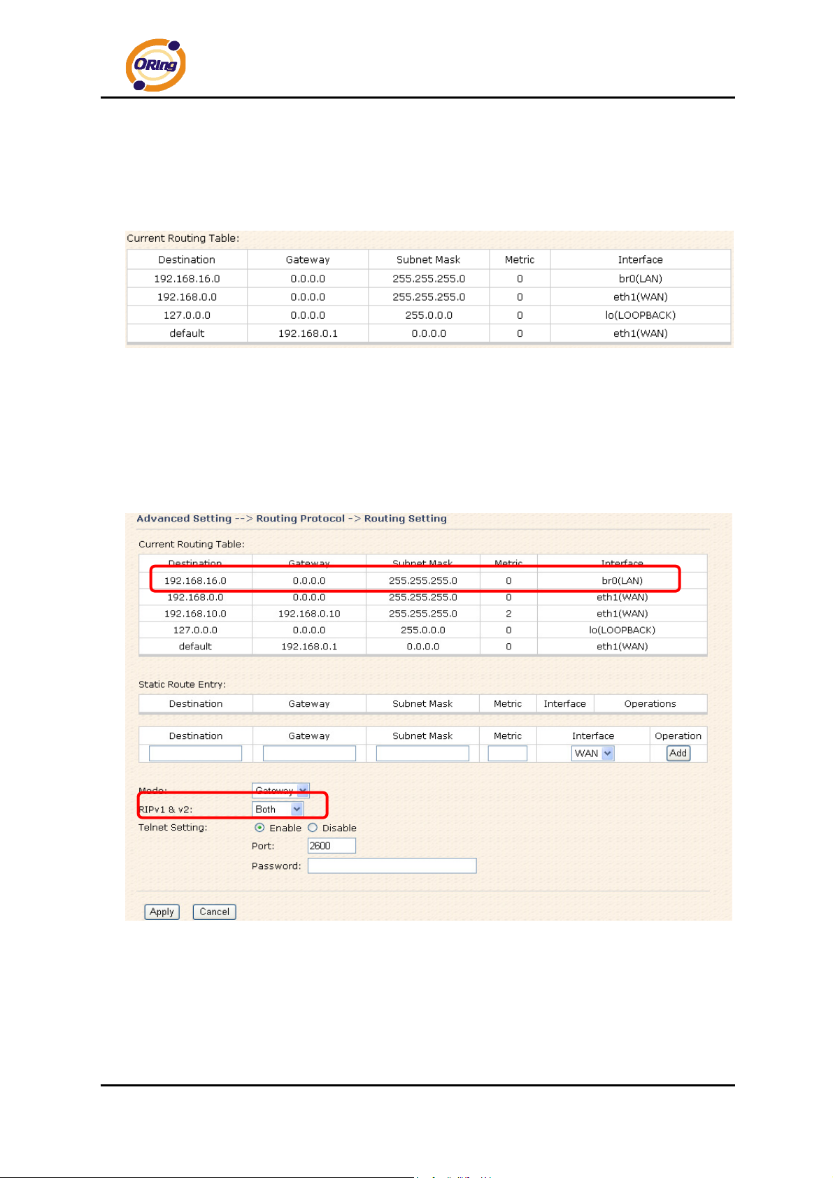
This page shows the information of routing table. The initial state of the router connect to the
WAN, it will be based on the outside networks to access the routing table automatically. You
can refer the shows about the bellow page.
The table shows the normal routing table
1. Use Dynamic Routing
Use the dynamic routing, you should not choose “Disable” about the RIPv1 & v2 in the
routers.
Click “Apply”, and you can see the more information in the Current Routing Table, which
shows the network segment of the other router.
ORing Industrial Networking Corp……………………………………………………………….…43
Page 48
IAR-120 / 120+ User’s Manual
Label
Description
Current Routing
Show the current the routing information.
Table
Static Router
Not RIP and enter the right value in the textbox will be showing.
Entry
Mode
If you want to the PC in the router can visit the outside network, only
choose the Gateway Mode; if or not, you choose the Router Mode.
RIPv1 &v2
Choose “Disable” in the Static routing.
Telnet Setting
Only use in the Dynamic routing.
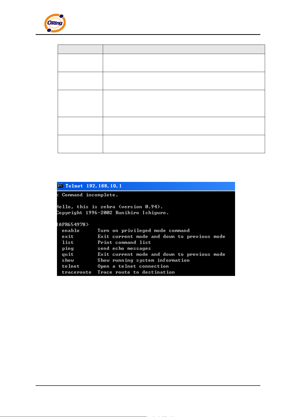
Simultaneously, only use the Telnet function in the dynamic routing. You can telnet the LAN
IP and there are many orders.
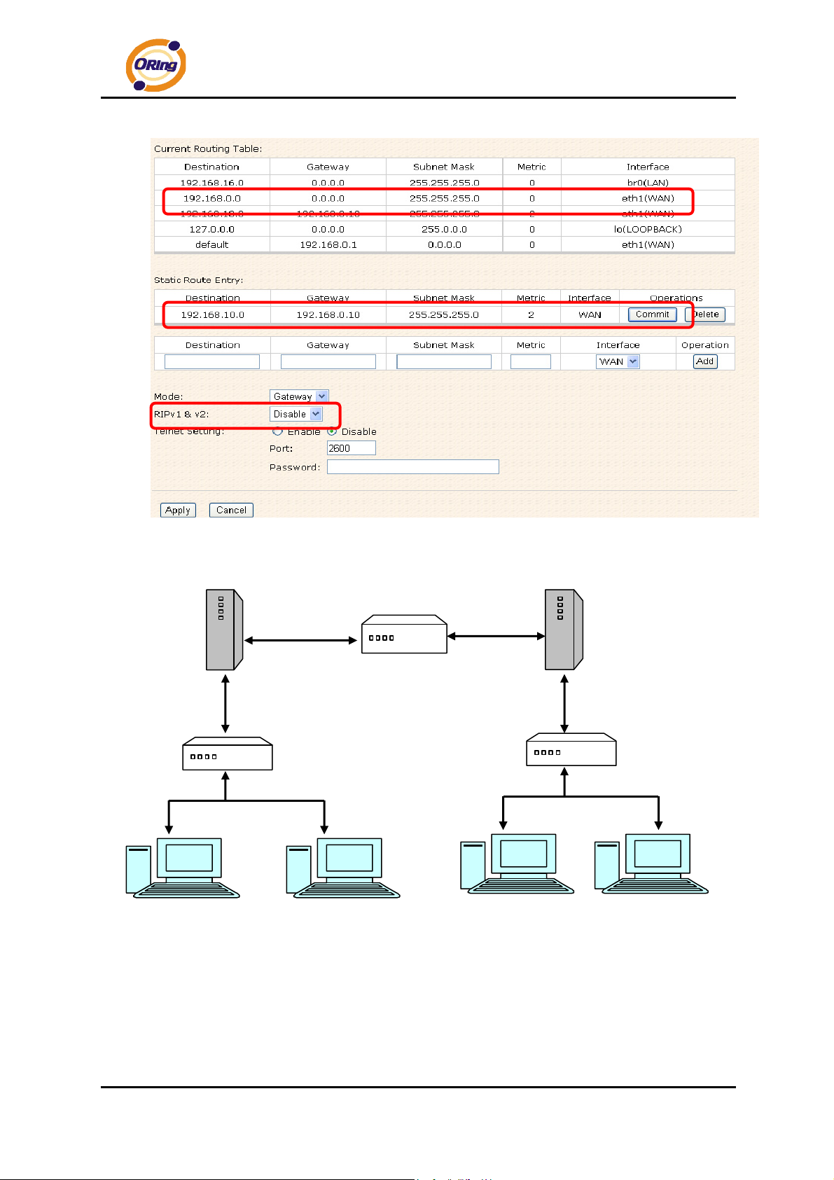
2. Use Static Routing
Use the Static routing, you should choose “Disable” about the RIPv1 & v2 in the routers.
Click “Apply”, and you can see the more information in the Current Routing Table and Static
Route Entry, which shows the network segment of the other router.
ORing Industrial Networking Corp. 44
Page 49
IAR-120 / 120+ User’s Manual
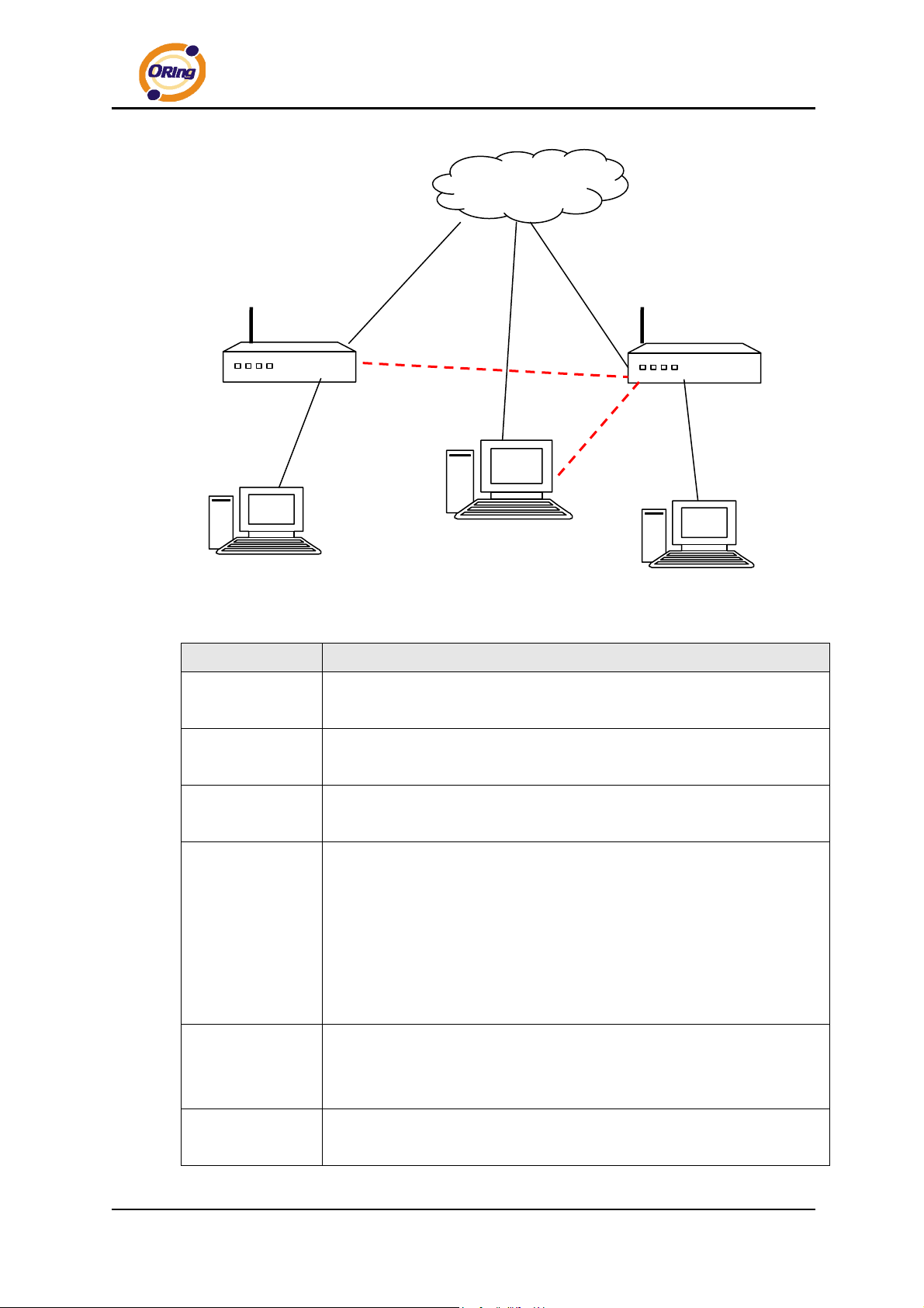
Use the dynamic routing; it will have many ways such as RIP, OSPF.BGP. In this router, we
use the RIP Protocol to finish the dynamic routing table.
Route1
Switch
Switch
PC1 PC2
The Routing Topography
Route2
Switch
RIP, Routing Information Protocol, is a dynamic routing protocol used in local and wide
area networks. As such it is classified as an interior gateway protocol (IGP) using the
distance-vector routing algorithm.
After all settings, PC1 can visit PC2 which is different network segment of the PC1.
ORing Industrial Networking Corp……………………………………………………………….…45
Page 50
Notification
1. Email/SNMP/Syslog
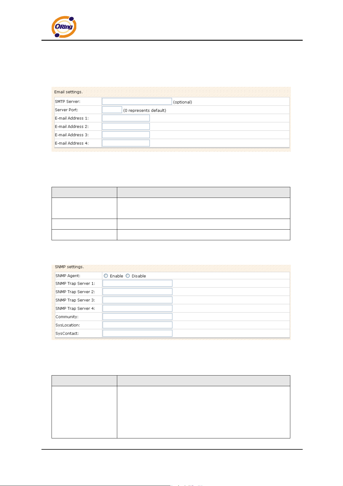
Email Settings
Email Settings Screen
The following table describes the labels in this screen.
Label Description
IAR-120 / 120+ User’s Manual
SMTP Server
Server Port
E-mail Address 1-4
SNMP Settings
The following table describes the labels in this screen.
Simple Message Transfer Protocol, enter the backup host to use if
primary host is not available while sending mail by SMTP server.
Specify the port where MTA can be contacted via SMTP server.
Enter the mail addresses.
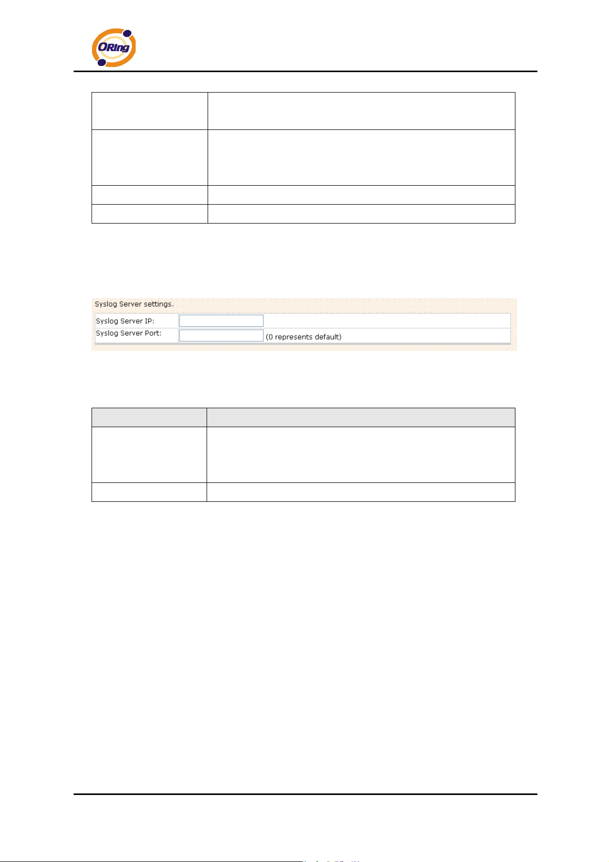
SNMP Settings
Label Description
SNMP (Simple Network Management Protocol) agent
communicates with the SNMP manager. The agent provides
SNMP Agent
ORing Industrial Networking Corp. 46
management information to the NMS by keeping track of various
operational aspects of the system. Turn on to open this service
and off to disable it.
Page 51
IAR-120 / 120+ User’s Manual
SNMP Trap Server
1-4
Community
SysLocation
SysContact
Specify the IP address of trap server, which is the address to
which SNMP trap messages are sent.
Community is essentially password to establish trust between
managers and agents. Normally "public" is used for read-write
community.
Specify sysLocation string.
Specify sysContact string.
Syslog Server Settings
Syslog Server Screen
The following table describes the labels in this screen.
Label Description
Syslog Server IP
Syslog Server Port
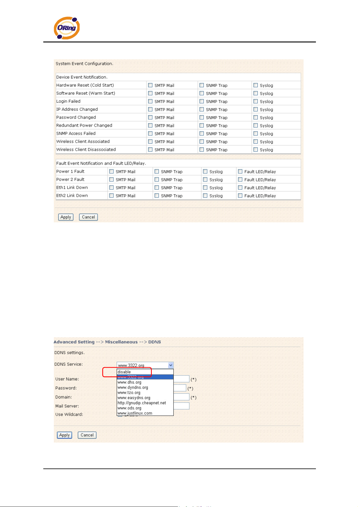
2. System Event
When specified event is triggered, the notification procedure will be performed
according to the type of the event. Which notification would be performed depends on
the selection of corresponding option in the Advanced Setting > Notification >
System Event page.
Not only the Syslog keeps the logs locally, it can also log to
remote server. Specify the IP of remote server. Leave it blank
to disable logging remotely.
Specify the port of remote logging. Default port is 514.
ORing Industrial Networking Corp……………………………………………………………….…47
Page 52
IAR-120 / 120+ User’s Manual
System Event Screen
System events record the activities of the Wireless Router system. When the setting
changes or action performs, the event will be sent to administrator by email. A trap will
also be sent to SNMP trap server. The Syslog will record the event locally and may
send the Syslog remotely to a Syslog server. If serious event occurred, such as the
power failure or link down, the fault led will be switched on as warning indication.
Miscellaneous (DDNS)
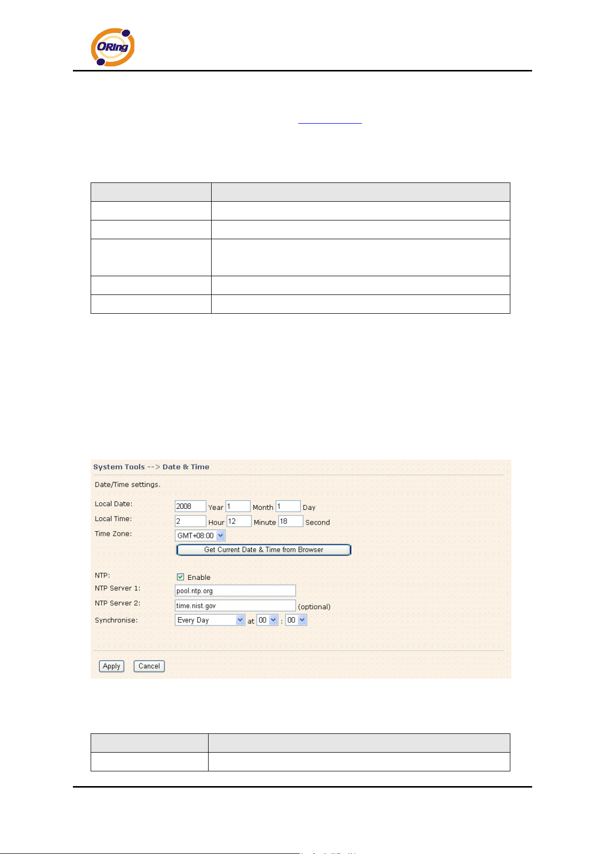
Dynamic Domain Name System is a method of keeping a domain name linked to a
changing IP address.
DDNS Screen
ORing Industrial Networking Corp. 48
Page 53
IAR-120 / 120+ User’s Manual
For example, Choose DDNS Service: www.3322.org
instructions:
The following table describes the labels in this screen.
Label Description
User Name
Password
Domain
Mail Server
Use Wildcard
Enter the user name for your DDNS account.
Enter the password for your DDNS account.
Enter the domain names provided by your dynamic DNS service
provider.
Enter the mail server if provided.
Check the box the enable wildcard option.
5.3.3 System Tools
Date & Time
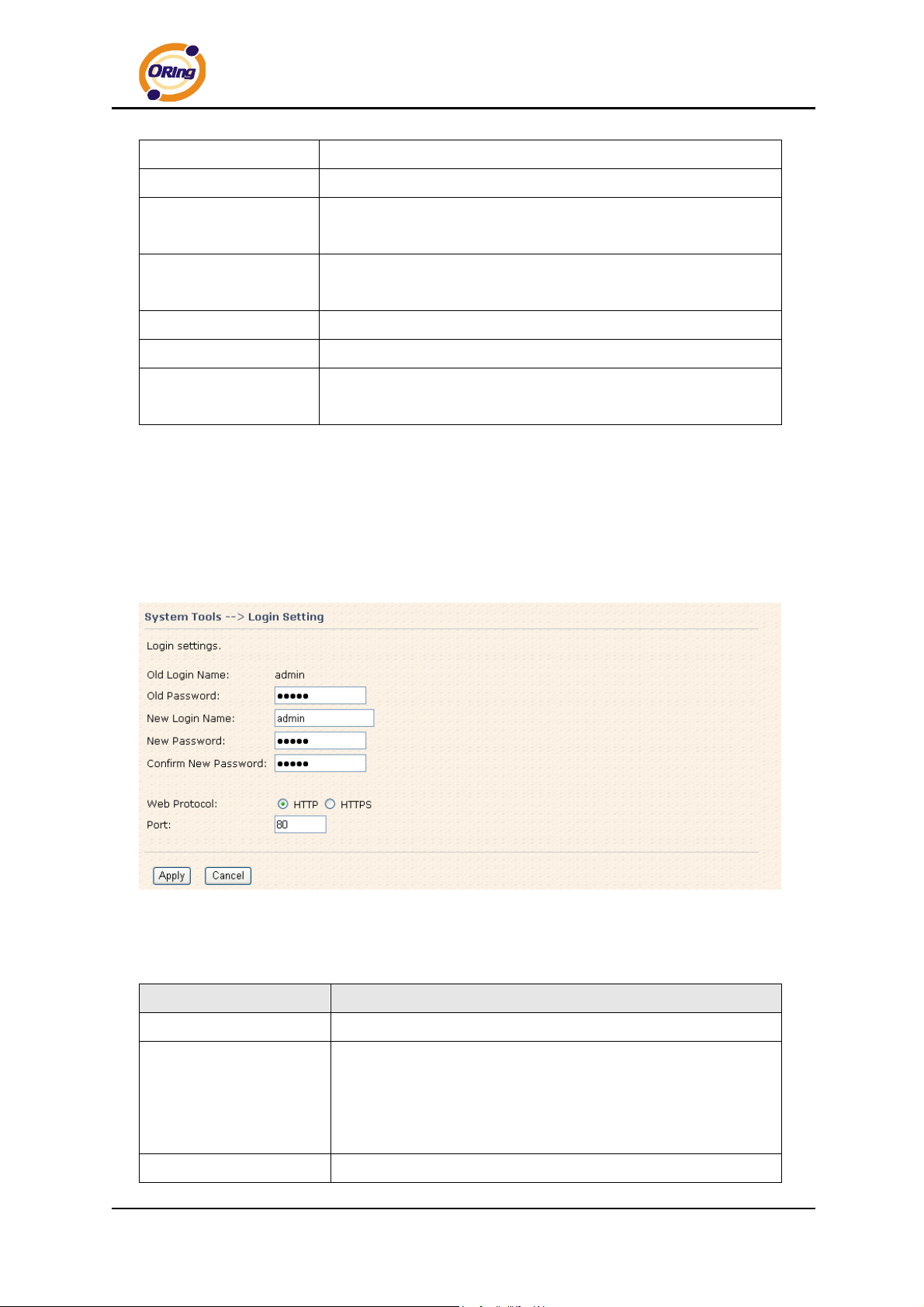
In this page, you can set the date & time of the device. The correct date & time will
and configure the following
be helpful for logging of system events. A NTP (Network Time Protocol) client can be
used to synchronize date & time with NTP server through internet.
Date & Time Screen
The following table describes the labels in this screen.
Label Description
Local Date
ORing Industrial Networking Corp……………………………………………………………….…49
Set local date manually.
Page 54
IAR-120 / 120+ User’s Manual
Local Time
Time Zone
Get Current Date &
Time from Browser
NTP
NTP Server 1
NTP Server 2
Synchronize
Set local time manually.
Select the time zone manually
Click this button; you can set the time from your browser.
Enable or disable NTP function to synchronize time from the NTP
server.
The primary NTP Server.
The secondary NTP Server.
This is the scheduled time when the NTP synchronization
performed.
Login Setting
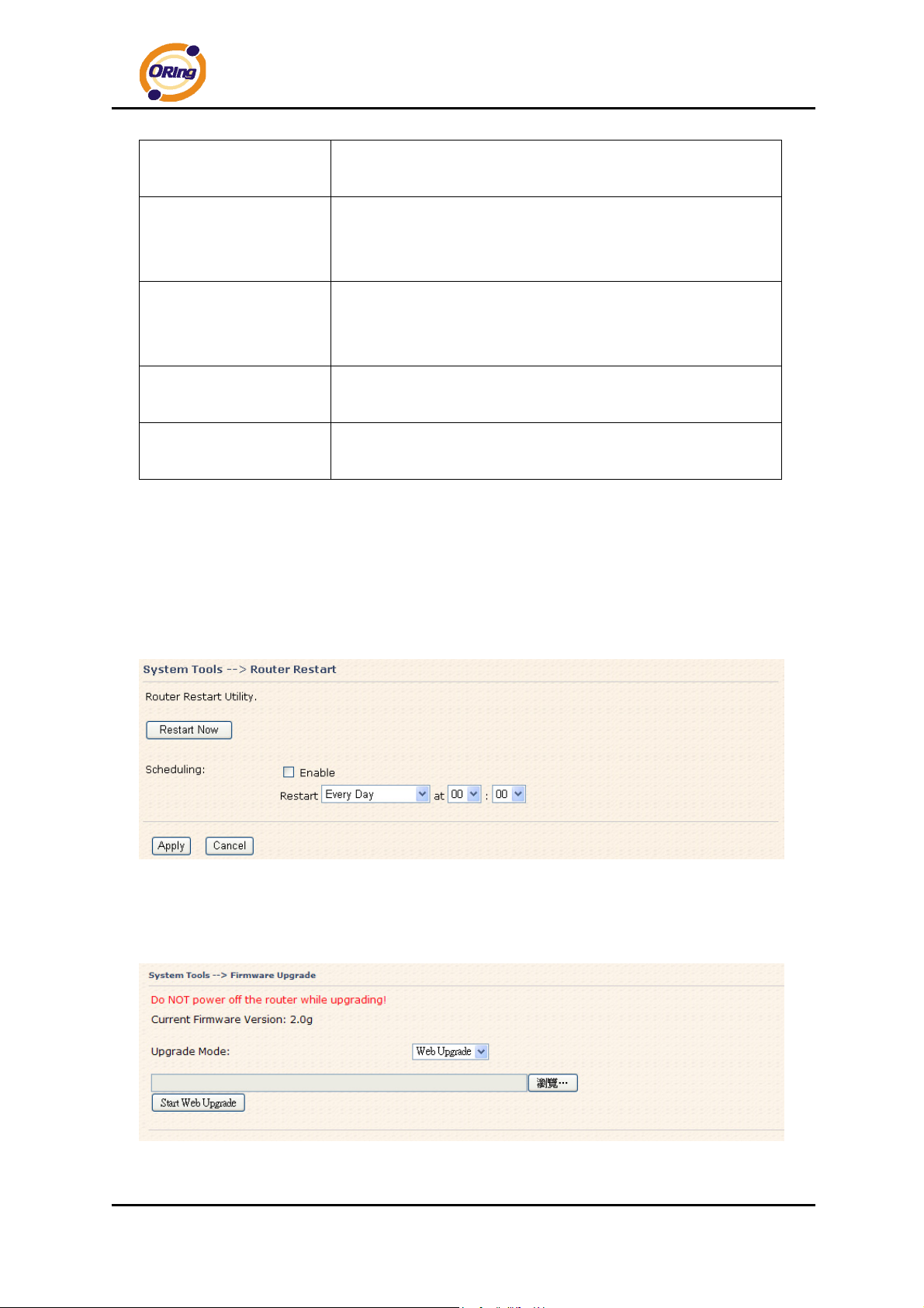
At this page, the administrator can change the login name and password. The
default name and password is admin and admin.
Login Setting Screen
The following table describes the labels in this screen.
Label Description
Old Name
Old Password
New Name
ORing Industrial Networking Corp. 50
This field shows the old login name.
Before making a new setting, you should provide the old
password for verification. Acceptable characters of this field
contains '0-9', 'a-z', 'A-Z' and must be between 0 to 15
characters in length. An empty password is also acceptable.
Enter a new login name. Acceptable characters of this field
Page 55
IAR-120 / 120+ User’s Manual
contains '0-9', 'a-z', 'A-Z' and must be between 1 to 15
characters in length. An empty name is not acceptable.
New Password
Confirm New Password
Web Protocol
Port
HTTPS (HTTP over SSL) is a Web protocol which encrypts and decrypts user page
requests as well as the pages that are returned by the Web server.
Enter a new login password. Acceptable characters of this
field contains '0-9', 'a-z', 'A-Z' and must be between 0 to 15
characters in length.
Retype the password to confirm it. Acceptable inputs of this
field contains '0-9', 'a-z', 'A-Z' and must be between 0 to 15
characters in length.
Choose the web management page protocol. HTTP and
HTTPS are both supported.
Choose the web management page port number. For HTTP,
default port is 80; For HTTPS, default port is 443.
Router Restart
If you want restart the router through the Warm Reset, click Restart Now to restart
the Wireless Router. Also, you can set a Scheduling time to make the router restart.
Router Restart Screen
Firmware Upgrade
Firmware Upgrade Screen
ORing Industrial Networking Corp……………………………………………………………….…51
Page 56
IAR-120 / 120+ User’s Manual
Newer firmware may provide better performance or function extensions. To
upgrade the new firmware, you need a firmware file which matches the model of this
AP router. It will take several minutes to upload and update the firmware. After the
upgrade is done successfully, reboot the router to utilized new firmware.
Important Notice: DO NOT POWER OFF THE ROUTER OR PRESS THE RESET
BUTTON WHILE THE FIRMWARE IS BEING UPGRADED.
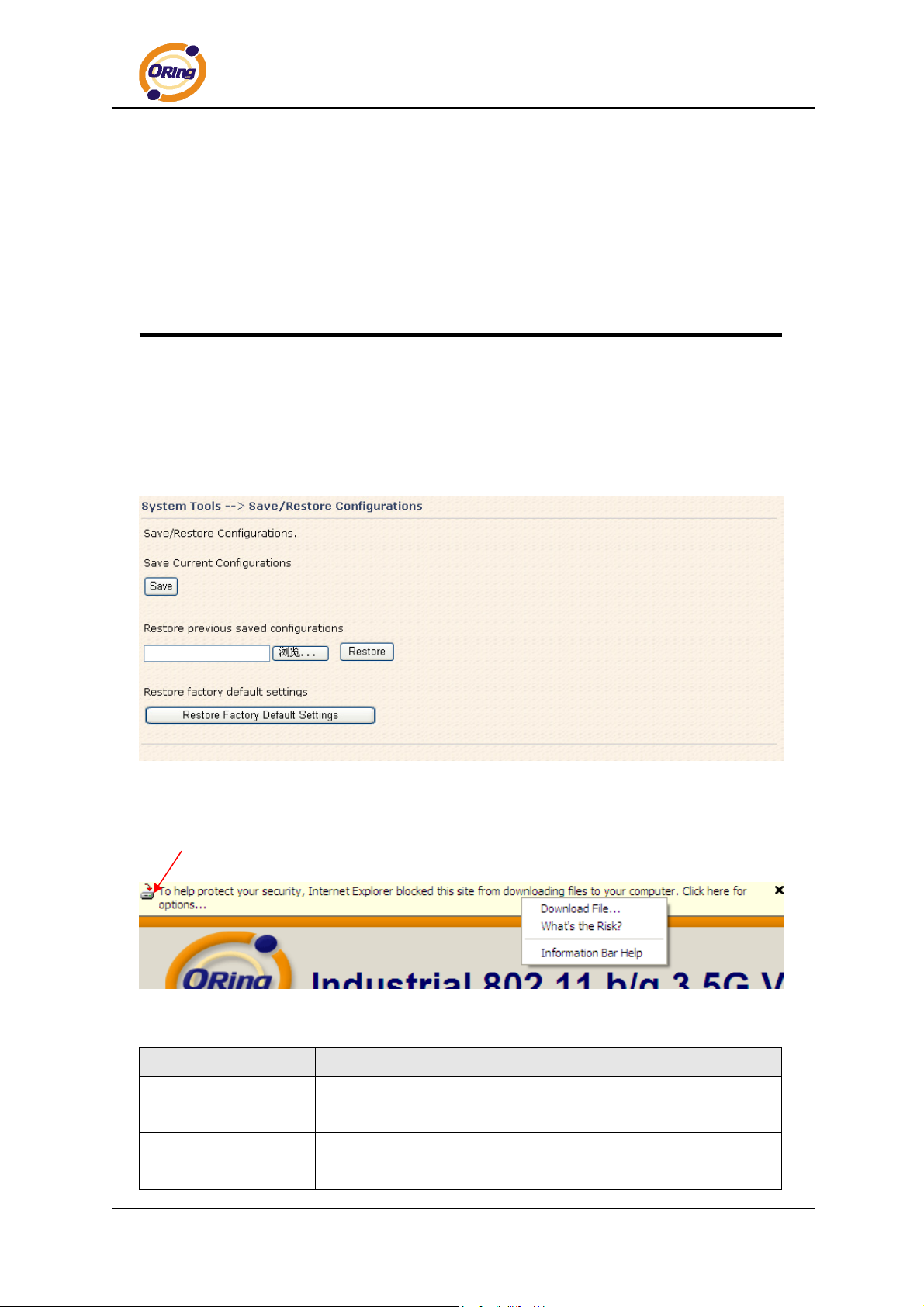
Save/Restore Configurations
Save/Restore Configurations Screen
Save: The configuration file can be downloaded. (Internet Explorer user will need to
click on the protection bar on top and click choose “download files”)
The following table describes the labels in this screen.
Label Description
Download
configuration
Upload configuration
The current system settings can be saved as a file into your PC.
The configuration can be restored to the router. To reload a
system settings file, click on Browse to browse your local hard
ORing Industrial Networking Corp. 52
Page 57
IAR-120 / 120+ User’s Manual
drive and locate the system settings file previously saved. Click
Upload when you have selected the file.
Restore Default
Settings
You may also reset the router to the factory settings by clicking on
Restore Default Settings. The router will reboot to validate the
default settings.
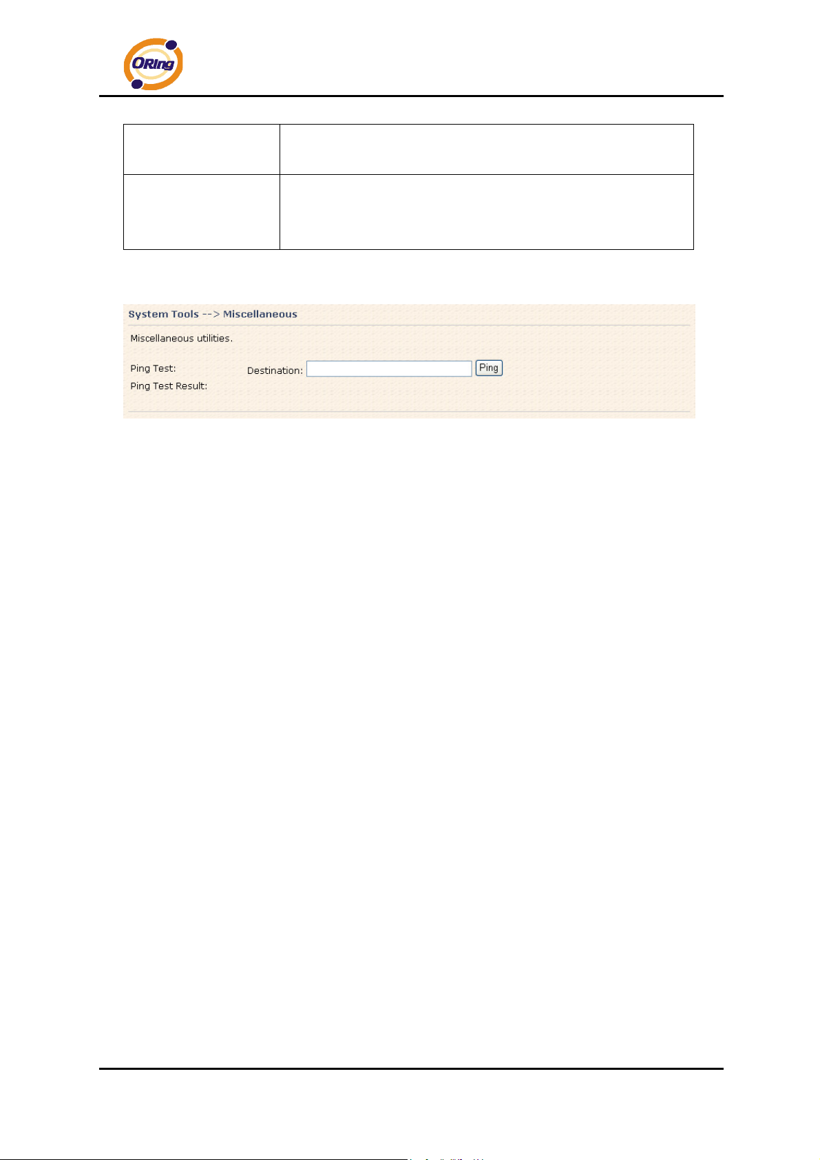
Miscellaneous (Ping)
Miscellaneous Screen
The Ping Test is used to send Ping packets to test if a computer whether it is on the
Internet or test if the WAN connection is OK. Enter a domain or IP in the destination
box and click Ping to test.
ORing Industrial Networking Corp……………………………………………………………….…53
Page 58
5.3.4 System Status
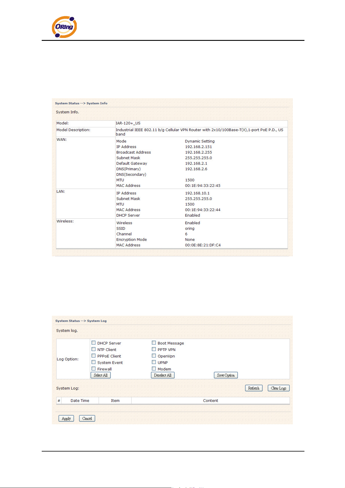
System Info
IAR-120 / 120+ User’s Manual
System Info Screen
This page displays the details information for the AP router including model name,
model description, firmware version, WAN, LAN and wireless settings.
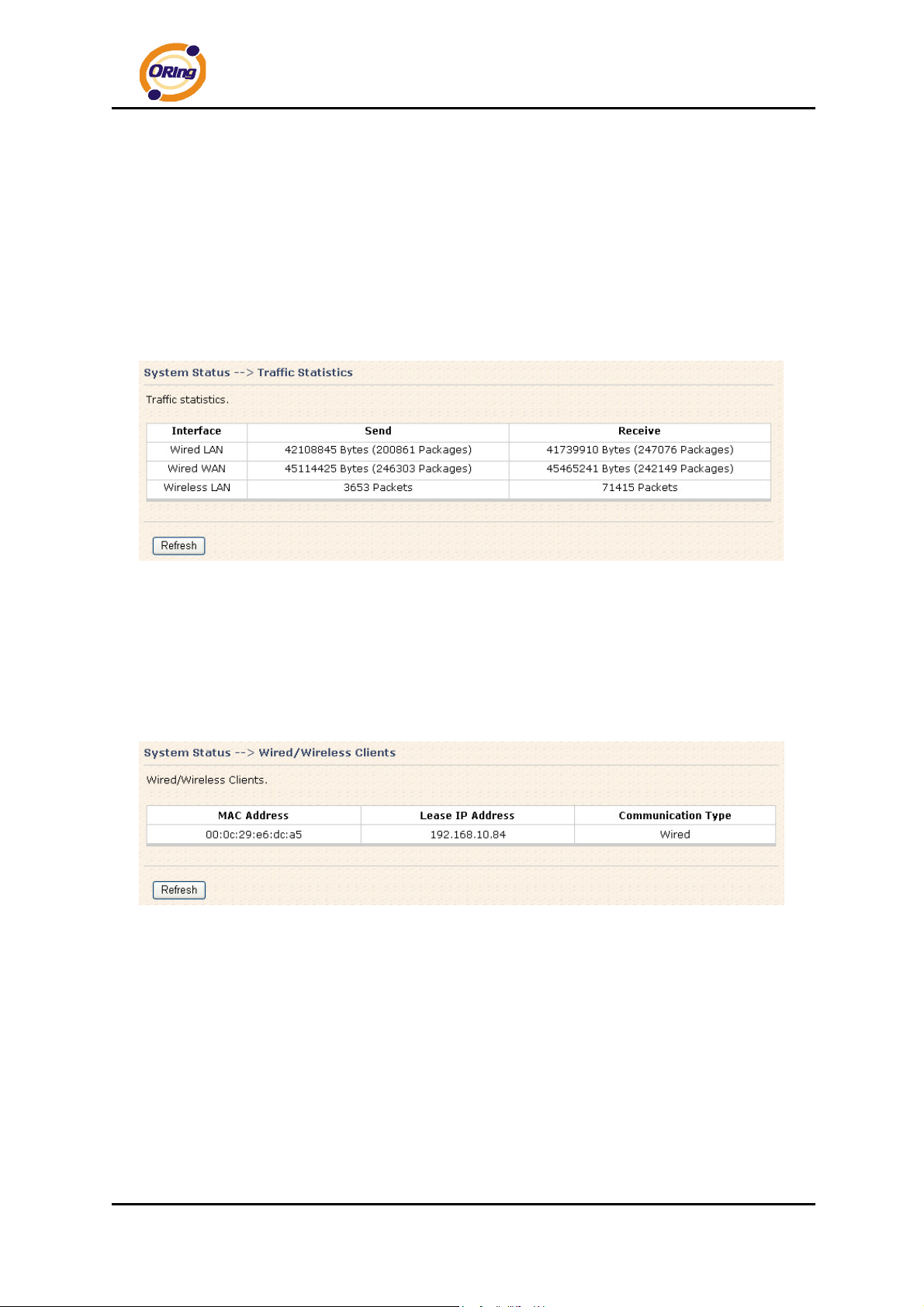
System Log
System Log Screen
ORing Industrial Networking Corp. 54
Page 59
IAR-120 / 120+ User’s Manual
The router keeps a running log of events and activities occurring on the router, several
filters are provided for displaying related log entries.
Click the button 'Refresh' to refresh the page.
Click the button 'Clear Logs' to clear the log entries.
Traffic Statistics
Traffic Statistics Screen
This page displays the network traffic statistics for both received and transmitted
packets through the Ethernet port and wireless connections.
Wired/Wireless Clients
Wired/Wireless Clients Screen
This page of the list displays the Mac Address and Lease IP Address of the
wired/wireless clients connected. Communication Type shows the physical
connection type of the client.
ORing Industrial Networking Corp……………………………………………………………….…55
Page 60
IAR-120 / 120+ User’s Manual
Technical Specifications
LAN Interface
RJ45 Ports 2 x 10/100Base-T(X), Auto MDI/MDI-X
Protection Built-in 1.5KV magnetic isolation
Protocols ICMP, IP, TCP, UDP, DHCP, BOOTP, ARP/RARP,
DNS, SNMP MIB II, HTTPS, SSH, SNMPV1/V2,
Trap, Private MIB
P.O.E. PD Present at ETH2 of IAR-120+
Power Device (IEEE802.3af):
IEEE 802.3af compliant input interface
Power consumption: 8Watts max.
Over load & short circuit protection
Isolation Voltage: 1000 VDC min.
Isolation Resistance: 10
WLAN Interface
Antenna Connector Reverse SMA
Radio Frequency Type DSSS, OFDM
Modulation IEEE802.11b: CCK, DQPSK, DBPSK
IEEE802.11g: OFDM with BPSK, QPSK, 16QAM,
64QAM
Frequency Band America/FCC: 2.412~2.462 GHz (11channels)
Europe CE/ETSI: 2.412~2.472 GHz (13channels)
Transmission Rate IEEE802.11b: 1/2/5.5/11 Mbps
IEEE802.11g: 6/9/12/18/24/36/48/54 Mbps
Transmit Power IEEE802.11b/g: 18dBm
Receiver Sensitivity -81dBm@11Mbps, PER< 8%;
-64dBm@54Mbps, PER< 10%
Encryption Security WEP: (64-bit, 128-bit key supported)
8
ohms min
WPA/WPA2:802.11i (WEP and AES encryption)
WPA-PSK (256-bit key pre-shared key supported)
802.1X and Radius supported
TKIP encryption
Wireless Security SSID broadcast disable
LED Indicators PWR 1(2) (P.O.E., IAR-120+) / Ready:
1) Red On: Power is on and booting up.
ORing Industrial Networking Corp. 56
Page 61

IAR-120 / 120+ User’s Manual
2) Green On: Power is on and functioning normally.
ETH1 (2) Link / ACT:
Orange ON/Blinking: 10 Mbps Ethernet
Green ON/Blinking: 100 Mbps Ethernet
WLAN Link/ACT: Green
WLAN Strength:1<25%, 2<50%, 3<75%, 4<100%
Fault: Power or LAN link down (Red)
Power Requirements
Power Input Voltage PWR1/2: 12 ~ 48VDC in 6-pin Terminal Block
Reverse Polarity Protection Present
Power Consumption 6 Watts (USB device not included)
Environmental
Operating Temperature -10 to 55oC
Storage Temperature -40 to 85oC
Operating Humidity 5% to 95%, non-condensing
Mechanical
Dimensions(W x D x H) 52 mm(W)x 106.1 mm( D )x 144.3 mm(H)
Casing IP-30 protection
Regulatory Approvals
Regulatory Approvals FCC Part 15, CISPER (EN55022) class A
EMS EN61000-4-2 (ESD), EN61000-4-3 (RS),
EN61000-4-4 (EFT), EN61000-4-5 (Surge),
EN61000-4-6 (CS)
Shock IEC 60068-2-27
Free Fall IEC 60068-2-32
Vibration IEC 60068-2-6
Warranty
3 years
ORing Industrial Networking Corp……………………………………………………………….…57
 Loading...