

ORiNG TINJ-101GT-M12, EN50155 Quick Installation Manual
Quick InstallationGuide
Version 1.0
Quick Installation Guide
Introduction
PRINTED ON RECYCLED PAPER
QIG
The is a PoE injector designed for industrial
environments, especiallyfor rolling stock,vehicle, and railwayapplications
due toits EN50155 compliance and M12 connectors. With one
10/100/1000 Base-T(X)port compliant with IEEE802.3at/af standards, the
is equipped with intelligent detection function. As a
result, the devices will not turn on power until it detects a valid PoE
signature from the connected PoE devices. This function can protect nonPoE compliant equipment connected to the same Ethernet cable from
damage and allow only IEEE 802.3at/802.3af compliant devices to be
powered bythe PoE injector. The PoE injectorcan function withany P.D.
equipment whichis fully compliantwith IEEE 802.3at/802.3afPoE standards.
TINJ-101GT-M12
TINJ-101GT-M12
Package Contents
Installation
Wall-mount
The devicecan be fixedto the wall.Follow the stepsbelow to installthe device onthe wall.
Hold the evice upright against the wall
Insert four screws through the large opening of the keyhole-shaped apertures at the
top and bottom of the unit and fastenthe screw tothe wall witha screwdriver.
Slide the evice downwards and tighten the four screws for added stability.
Step 1:
Step 2:
Step 3:dd
The product isshipped with thefollowing items. Ifany of theseitems is
missing ordamaged, please contactyour customer servicerepresentative for
assistance.
Preparation
Before youbegin installing thedevice, make sureyou have allof the package
contents availableand a PCwith Microsoft InternetExplorer 6.0 orlater, for
using web-basedsystem management tools.
Elevated OperatingAmbient:
ReducedAir Flow:
Mechanical Loading:
Circuit Overloading:
If installedin a closed environment, makesure
the operating ambient temperature is compatible with the maximum
ambient temperature (Tma) specified by the manufacturer.
Make surethe amount ofair flow requiredfor safe operation
of theequipment is notcompromised during installation.
Make surethe mounting ofthe equipment is not in a
hazardous conditiondue to unevenmechanical loading.
Consideration shouldbe given tothe connection ofthe
equipment tothe supply circuitand the effectthat overloading ofthe circuits
might haveon overcurrent protectionand supply wiring.Appropriate
consideration ofequipment nameplate ratingsshould be used when addressing
this concern.
Safety & Warnings
Contents
TINJ-101GT-M12or
TINJ-101GT-M12-24V
Pictures Number
1
QIG
1
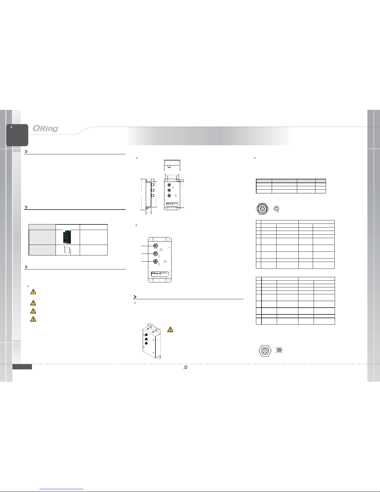
Dimension
Panel Layouts
Front View
1.
2.
3. Powerinput port
4. PoEstatus LED
5. Powerstatus LED
Data inputport
PoE port
Network Connection
The deviceprovides one datainput port andone PoE dataoutput port inM12 connector.According
to the link type, the device uses CAT 3,4, 5, 5e UTP cables to connect to any other network
devices (Pcs,servers, switches, routers,or hubs). Please refer to the following table for cable
specifications.
TINJ-101GT-M12
1907-2-29-TINJ101GTM12-1.0
PoE
INJECTOR
PoE
INJECTOR
EN50155
INDUSTRIAL
1
3
4
Instead ofscrewing the screwsin all theway, itis advised to
leave aspace of about2mm to allowroom for slidingthe switch
between thewall and thescrews.
For pinassignments of theLAN ports, pleaserefer to thefollowing tables.
178.2
R2.5
R4.00
40.0
15.0
7.50
150.0
44.4
73.9
138.0
88.9
EN50155 Industrial PoE Injector
TINJ-101GT-M12
PoEOUT
PoE
V-
V+
N.C.
N.C.
N.C.
PWR
PWR
4
5
6
7
8
21
1DC+
2DD+
3DD4DA5DB+
6DA+
7DC8DB-
3
1DC+
2DD+
3DD4DA-/PoEVout+
5DB+/PoEVout6DA+/PoEVout+
7DC8DB-/PoEVout-
DataIN
TINJ-101GT-M12
PoEOUT
PoE
V-
V+
N.C.
N.C.
N.C.
PWR
PWR
4
5
6
7
8
21
1DC+
2DD+
3DD4DA5DB+
6DA+
7DC8DB-
3
1DC+
2DD+
3DD4DA-/ PoE Vout+
5DB+/PoE Vout6DA+/PoE Vout+
7DC8DB-/PoE Vout-
DataIN
TINJ-101GT-M12
2
5
Cable Typesand Specifications:
Cable Type Max. Length Connector
10BASE-TX Cat. 3, 4,5 100-ohm UTP 100m (328 ft) M12
100BASE-TX C at.5 100-ohm UTP UTP 100m (328 ft) M12
1000BASE-T C at.5/Cat. 5e 100-ohmU TP UTP 100 m( 328ft) M1 2
4
5
6
7
8
21
3
1DC+
2DD+
3DD4DA- / PoE Vout+
5DB+/PoEVout6DA+/PoEVout+
7DC8DB-/PoEVout-
10/100 Base-T(X)
M12Input (DataOnly) M12Output (Dataand Power)
Pin Symbol
Description
Symbol
Description
1 NC Not Connected NC NotConnected
2 NC Not Connected NC NotConnected
3 NC Not Connected NC NotConnected
4Rx- DataReceive Rx-(Vdc+)
Data Receiv e and
Feeding power(+)
5 Tx+ Data Transmit Tx+ (Vdc-)
Data Transmitand
Feeding power(-)
6Rx+ DataReceive Rx+(Vdc+)
Data Receiv e and
Feeding power(+)
7 NC Not Connected NC NotConnected
8Tx- DataTransmitTx-(Vdc-)
Data Transmitand
Feeding power(-)
1000 Base-T
M12Input (DataOnly) M12Output (Dataand Power)
Pin Symbol Description Symbol Description
1
BI_DC+
DataBI_DC+
BI_DC+
Data BI_DC+
2
BI_DD+
Data BI_DD+
BI_DD+
Data BI_DD +
3
BI_DD-
Data BI_DD-
BI_DD-
Data BI_DD-
4
BI_DA-
Data BI_DA-
BI_DA-
(Vdc+)
Data BI_DA- and
Feeding Pow er(+)
5
BI_DB+
DataBI_DB+
BI_DB+
(Vdc-)
DataBI_DB+andFeeding
Power(-)
6
BI_DA+
DataBI_DA+
BI_DA+
(Vdc+)
DataBI_DA+ andFeeding
Power(+)
7
BI_DC-
Data BI_DC-
BI_DC-
Data BI_D C-
8
BI_DB-
Data BI_DB-
BI_DB-
(Vdc-)
Data BI_DB- and
FeedingPower(-)
Power inputs
The deviceprovides one set of power supply using theM12 5-pin female
connector onthe front panel. Please refer to the following figure for pin
assignments.
V-
V+
N.C.
N.C.
N.C.
QIG
Quick InstallationGuide
PRINTED ON RECYCLED PAPER
Quick Installation Guide
ORing IndustrialNetworking Corp.
Copyright© 2015 ORing
All rightsreserved.
TEL: +886-2-2218-1066
FAX:+886-2-2218-1014
Website: www.oring-networking.com
E-mail: support@oring-networking.com
Version 1.0
QIG
Specifications
Protection
ShortCircuit Protection
OverLoad Protection
Present
Present
Physical Characteristic
Enclosure
IP-40
Dimension(WxDxH)
88.9(w) x 40(D) x178.2 (H)mm (3.5 x1.57 x 7.02inch.)
Weight (g)
385g
Environmental
-40to85C(-40to185F)
oo
StorageTemperature
5%to 95% Non-condensing
OperatingHumidity
Regulatory Approvals
FCCPart 15, CISPR(EN55022) class A,EN50155 (EN50121-3-2, EN55011,EN50121-4)
EMI
EN61000-4-2(ESD), EN61000-4-3 (RS),EN61000-4-4 (EFT), EN61000-4-5(Surge),
EN61000-4-6(CS), EN61000-4-8, EN61000-4-11
EMS
IEC60068-2-27
Shock
IEC60068-2-32
IEC60068-2-6
Vibration
FreeFall
Warranty
5years
EN60950-1
Safety
-25to75C(-13to167F)
oo
OperatingTemperature
ORing SwitchModel
10/100/1000BaseT(X) with
P.S.E.PortsinM12Auto
MDI/MDIX
1xM12connector(8pinA-coding)
Physical Ports
Operating Voltage
InputVoltage
50~57VDCon4-pinterminalblock
TINJ-101GT-M12
50V/ 600mA, 30Watts max.
OutputPower
Configurations
After installingthe switch and connecting cables, start the evice by
turning onpower. Thegreen power LEDshould turn on. Please refer to the
following tablet for LED indication.
d
LED Color Status Descript ion
Power Green On Power ison
On PoE deviceis detected
Blinking Detecting PoEdevice
PoE
Blue
Off No PoE device isdetect ed
TINJ-101GT-M12-24V
10/100/1000BaseT(X) Ports
inM12AutoMDI/MDIX
1xM12connector(8pinA-coding)
12~57VDCon4-pinterminalblock
446g
TINJ-101GT-M12
PoE
INJECTOR
PoE
INJECTOR
EN50155
INDUSTRIAL
EN50155 Industrial PoE Injector
TINJ-101GT-M12
 Loading...