

ORiNG DGS-9168GP-SS-AIO_S, DGS-9168GP-MM-AIO_S Quick Installation Manual
Quick InstallationGuide
Version 1.0
Quick Installation Guide
Introduction
PRINTED ON RECYCLED PAPER
The is amanaged industrial Ethernetswitch
with sixteen10/100/1000Base-T(X) ports andeight 100/1000Base-X SFP
ports. Withtwo sets ofbypass ports (theoptical ports) thatensure constant
network connectivityif power outageor node failureoccurs, the trafficwill
bypass theinactive switch andcontinue to transferto the next active
switch. The switch supports Ethernet Redundancy protocols, O-Ring
(recovery time <30ms over 250units of connection) and MSTP
(RSTP/STP compatible) to protect mission-critical applications from
network interruptions or temporary malfunctions withfast recovery
technology.With a wideoperating temperature from-40 C to 70 C,the
device canbe managed centrallyvia ORing’s proprietaryOpen-Vision
platform aswell as viaWeb-based interfaces, Telnet, andconsole (CLI).
The switchis one of the most reliable choices for highly-managed and
fiber Ethernet applications.
DGS-9168GP-AIO_S series
oo
Preparation
Before youbegin installing theswitch, make sureyou have allof the package
contents availableand a PCwith Microsoft InternetExplorer 6.0 orlater, for
using web-basedsystem management tools.
Circuit Overloading:Consideration should begiven to theconnection of theequipment to
the supplycircuit and theeffect that overloadingof the circuitsmight have onovercurrent
protection andsupply wiring.Appropriate consideration ofequipment nameplate ratings
should beused whenaddressing this concern.
Safety & Warnings
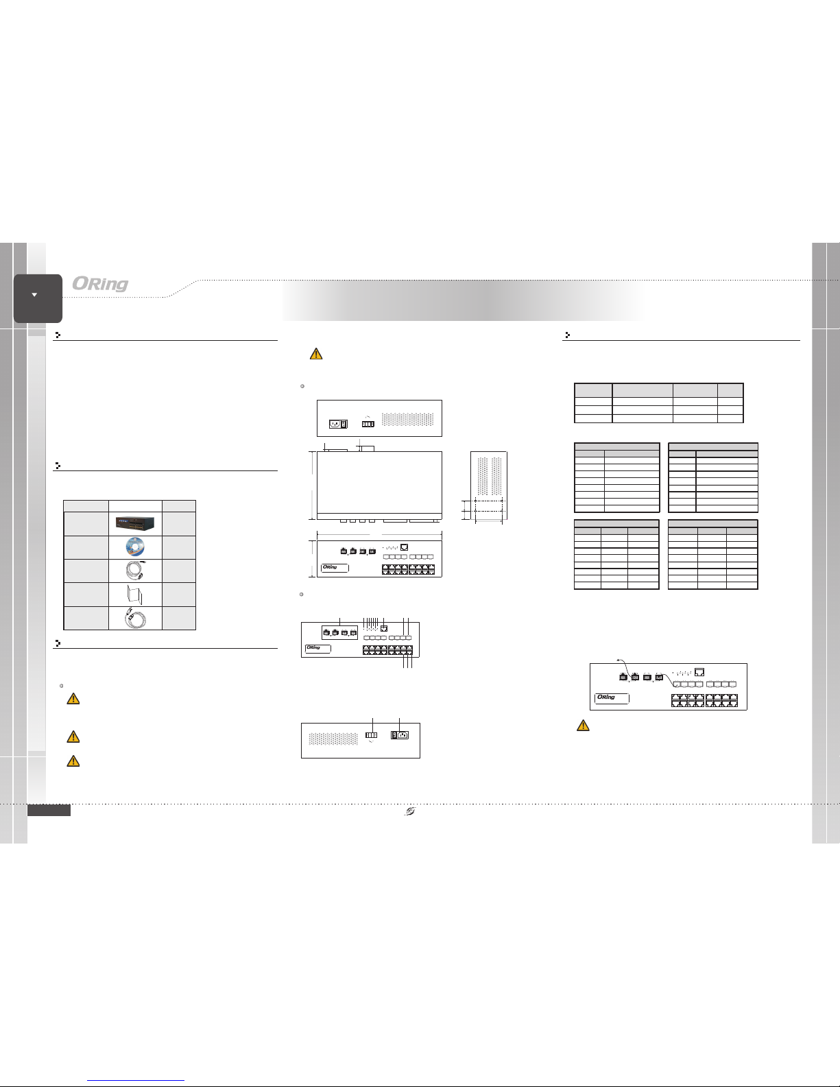
Dimension
Panel Layouts
1. Fiberbypass ports
2. Resetbutton
3. PowerLED
4. PWR1LED
5. PWR2LED
6. Ringmaster LED
7. Ringstatus LED
8. Faultindicator
9. Consoleport
10. 100/1000Base-X fiber port
11. LNK/ACTLED for fiberport
12. 10/100/1000Base-T(X) LAN port
13. LNK/ACTLED for LANport
14. SpeedLED for LANport
Package Contents
Contents
CD
DGS-9168GP-AIO_S
Pictures Number
X1
X1
Front Panel
The device is shippedwith the followingitems. If anyof these itemsis
missing ordamaged, please contactyour customer servicerepresentative for
assistance.
QIG
Console Cable
X1
X1
1
Network Connection
QIG
DGS-9168GP-AIO_S
1907-2-29-DGS9168GPAIO-1.0
The switchprovides standard Ethernetports. Accordingto the linktype, the switchuses CAT 3,
4, 5,5eUTP cables toconnect to anyother network devices(PCs, servers, switches,routers, or
hubs). Pleaserefer to thefollowing table forcable specifications.
Industrial Desktop Managed Gigabit
Switch
SWITCH
INDUSTRIAL
Desktop
DGS-9168GP-AIO_S
Network
B
Monitor
A
TX
RX
B
TX RX TX RXATX RX
PWR1
PWR
Console
Reset
11520bps,
8,N,1
PWR2 Ring
R.M Fault
G2
G1
G4
G3
10/100/1000T
G6
G5
G8
G7
G22
G23
G20
G21 G18
G19
G20
G17
100/1000X
DGS-9168GP-AIO_S
165.00
300.00
88.00
24.00
20.75
63.60
14.70
3.00
3.70
AC100-240V
50-60HZ
Relay
2 3 45678 9 1011
12 13 14
Rear Panel
12
1. Powersocket of powerinput for
AC 100V~240V/ 50~60Hz
2. Relayoutput to carrycapacity of
1A at24VDC
Cable Typesand Specifications:
Cable Type Max. Length Connector
10BASE-T Cat. 3, 4, 5100- ohm UTP 100m (328 ft) R J-45
100BASE-TX Cat. 5100-ohmUTP UTP 100 m(328 ft) RJ-45
1000BASE- T Cat. 5 /Cat.5e 100-ohm UTP UTP1 00m (328ft) RJ-45
10/100 Base-T(X) MDI/MDI -X
PinNu m ber MDI port MDI-Xport
1 TD+(transmit) RD +(receive)
2 TD-(transmi t) RD -(receive)
3RD+(receive)TD+(transmit)
4NotusedNotused
5NotusedNotused
6RD-(receive)TD-(transmit)
7NotusedNotused
8NotusedNotused
1000Base-T MDI/MDI-X
PinNumber MDIport MDI-Xport
1BI_DA+BI_DB+
2BI_DA-BI_DB-
3 BI_DB+ BI_DA+
4 BI_DC+ BI_DD+
5 BI_DC- BI_DD-
6BI_DB-BI_DA-
7 BI_DD+ BI_D C+
8 BI_DD- BI_DC-
1000Base-T RJ-45 Port
PinNumber Assignment
1BI_DA+
2BI_DA-
3BI_DB+
4BI_DC+
5 BI_DC-
6BI_DB-
7BI_DD+
8 BI_DD-
10/100 Base- T(X) RJ-45 Po rt
PinNumber Assign ments
1TD+
2TD-
3 RD+
4 Not used
5 Not used
6RD-
7 Not used
8 Not used
For pinassignments for differenttypes of cables,please refer tothe following tables.
Note: “+”and “-” signsrepresent the polarityof the wiresthat make upeach wire pair.
Toconnect the consoleport to anexternal management device,you need anRJ-45 to DB-9
cable, whichis also suppliedin the package.Below is theconsole port pinassignment
information.
Console PortPin Definition
The device provides two sets of bypass fiber ports, giving the SFP fiber ports
additional redundancy capabilities. Connect a LC fiber cable from a fiber port to a
monitor porton the frontpanel and anotherLC fiber cablefrom the correspondingnetwork
port toanother switch. When the switchbreaks down, incomingtraffic will travelthrough the
bypass module and ontoanother active switchconnected to thenetwork port.
optical
Optical BypassConnection
The fiberport will stillwork if itis not connectedto any monitorport. However,the
fiber portwill not havebypass ability whenthe device isdown.
G10
G9
G12
G11
G14
G13
G16
G15
Network
B
Monitor
A
TX
RX
B
TX RX TX RXATX RX
PWR1
PWR
Console
Reset
11520bps,
8,N,1
PWR2Ring
R.M Fault
G2
G1
G4
G3
10/100/1000T
G6
G5
G8
G7
G22
G23
G20
G21 G18
G19
G20
G17
100/1000X
DGS-9168GP-AIO_S
G10
G9
G12
G11
G14
G13
G16
G15
Network
B
Monitor
A
TX
RX
B
TX RX TX RXATX RX
PWR1
PWR
Console
Reset
11520bps,
8,N,1
PWR2 Ring
R.M Fault
G2
G1
G4
G3
10/100/1000T
G6
G5
G8
G7
G22
G23
G20
G21 G18
G19
G20
G17
100/1000X
DGS-9168GP-AIO_S
G10
G9
G12
G11
G14
G13
G16
G15
Power Cable
X1
Elevated OperatingAmbient:
ReducedAir Flow:
Mechanical Loading:
If installed in a closed or multi-unit rack
assembly,the operating ambienttemperature of therack environment maybe
greater thanroom ambient. Therefore,consideration should begiven to
installing theequipment in anenvironment compatible withthe maximum
ambient temperature(Tma) specified bythe manufacturer.
Installation of the equipment in a rack should be such
that the amount of air flow required for safe operation of the equipment is
not compromised.
Mounting of the equipment in the rack should be
such that a hazardous condition is not achieved due to uneven mechanical
loading.
AC100-240V
50-60HZ
Relay
QIG
Quick InstallationGuide
PRINTED ON RECYCLED PAPER
Version 1.0
Quick Installation Guide
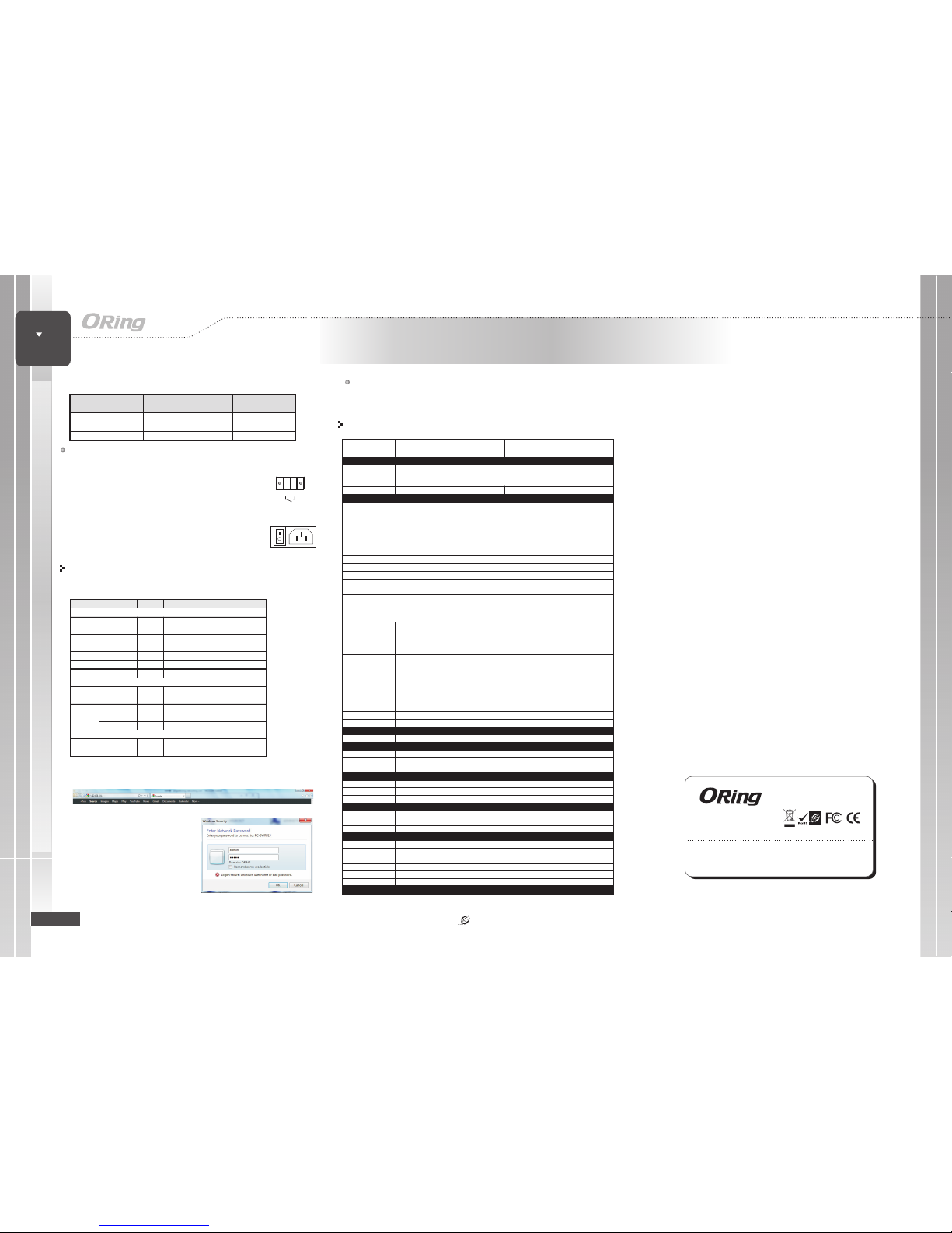
Configurations
After installingthe switch, thegreen power LEDshould turn on.Please refer to
the followingtablet for LEDindication.
1. Launchthe Internet Explorerand type inIP address ofthe switch.The default staticIP
address is192.168.10.1
2. Login with defaultuser name andpassword
(both are ). After logging in,you
should see the following screen. For more
information on configurations, pleaserefer to
the usermanual. For informationon operating
the switchusing ORing’s Open-Vision
management utility,please goto ORing
website.
admin
Follow thesteps to setup the switch:
Power
RedundantInput power
Powerconsumption(Typ.)
Dual100~240V AC powerinputs in singlepower socket
25Watts
Overloadcurrent protection
Present
PhysicalCharacteristic
Enclosure
IP-30
Dimension(WxDxH)
300(W)x165(D)x88(H)mm(11.8x6.49x3.46inch)
RS-232Serial Console Port
SwitchProperties
Switchlatency: 7 us
Switchbandwidth: 48Gbps
Max.Number of AvailableVLANs: 256
IGMPmulticast groups: 128for each VLAN
Portrate limiting: UserDefine
Https/ SSH enhancenetwork security
SecurityFeatures
DeviceBinding security feature
Enable/disableports, MAC basedport security
Portbased network accesscontrol (802.1x)
VLAN(802.1q) to segregateand secure networktraffic
Radiuscentralized password management
SNMPv3encrypted authentication andaccess security
Https/ SSH enhancenetwork security
SoftwareFeatures
STP/RSTP/MSTP(IEEE 802.1D/w/s)
RedundantRing (O-Ring) withrecovery time lessthan 30ms over250 units
TOS/Diffservsupported
Qualityof Service (802.1p)for real-time traffic
VLAN(802.1Q) with VLANtagging and GVRPsupported
IGMPSnooping for multicastfiltering
IP-basedbandwidth management
Application-basedQoS management
DOS/DDOSauto prevention
Portconfiguration, status, statistics,monitoring, security
DHCPServer/Clientsupport
SMTPClient
ModbusTCP
NetworkRedundancy
O-Ring,Open-Ring, O-chain, MRP,Fast Recovery,MSTP (RSTP/STPcompatible)
RS-232in RJ45 connectorwith console cable. Baud ratesetting: 115200bps, 8,N, 1
Weight (g)
2326g
Weight (g)
710g 740g722g 735g 735g 740g
Environmental
-40to85C(-40to185F)
oo
StorageTemperature
-40to70C(-40to158F)
oo
OperatingTemperature
5%to 95% Non-condensingOperatingHumidity
RegulatoryApprovals
FCCPart 15, CISPR(EN55022) class AEMI
EN61000-4-2(ESD), EN61000-4-3 (RS),EN61000-4-4 (EFT), EN61000-4-5(Surge),EN61000-4-6 (CS), EN61000-4-8,EN61000-4-11
EMS
IEC60068-2-27Shock
IEC60068-2-32
IEC60068-2-6Vibration
EN60950-1
Safety
FreeFall
Warranty
5years
Specifications
ORingSwitch Model
DGS-9168GP-SS-AIO_S
PhysicalPorts
Technology
EthernetStandards
IEEE802.3 for 10Base-T
IEEE802.3u for 100Base-TXand 100Base-FX
IEEE802.3z for 1000Base-X
IEEE802.3ab for 1000Base-T
IEEE802.3ad for LACP(Link Aggregation ControlProtocol)
IEEE802.3x for Flowcontrol,
IEEE802.1p for COS(Class of service)
IEEE802.1Q for VLANTagging
IEEE802.1w for RSTP(Rapid Spanning TreeProtocol
IEEE802.1s for MSTP(Multiple Spanning TreeProtocol)
IEEE802.1x for Authentication
IEEE802.1AB for LLDP(Link Layer DiscoveryProtocol)
10/100/1000Base-T(X)Ports
inRJ45 Auto MDI/MDIX
MACTable
8K
PriorityQueues
8
Processing
Store-and-Forward
16
100/1000Base-Xwith SFP port
8
QIGQIG
DGS-9168GP-AIO_S
Industrial Desktop Managed Gigabit
Switch
SWITCH
INDUSTRIAL
Desktop
DGS-9168GP-AIO_S
DGS-9168GP-MM-AIO_S
Wiring
The relaycontacts of the2-pin terminal block connector are used to
detect user-configured events. The two wires attached to the fault
contacts form a close circuit when a user-configured event is
triggered. If a user-configured event does not occur, the fault circuit
remains opened.
Power inputs
Fault Relay
Relay
For powersupply, simplyinsert the ACpower cable tothe power
connector atthe back ofthe switch andturn on thepower switch. The
input voltageis 100V~240V /50~60Hz
AC PowerConnection
Resetting
Toreboot the switch,press the button for 2-3 seconds.
Torestore the switchconfigurations back tothe factory defaults,press the button for 5
seconds.
Reset
Reset
LCBypass Port Type
Single-Mode Multi-Mode
FaultContact
Relay
Relayoutputtocarrycapacityof1Aat24VDC
ORing IndustrialNetworking Corp.
Copyright© 2014 ORing
All rightsreserved.
TEL: +886-2-2218-1066
FAX:+886-2-2218-1014
Website: www.oring-networking.com
E-mail: support@oring-networking.com
BufferSize
4Mbit
JumboFrame
9.6KBytes
LED Color St at us Description
System LED i ndicators
PWR Green On
Systemis on and power supplies are
functioningproperly.
PW1 Green On Power m odule 1 activ ated
PW2 Green On Power m odule 2 activ ated
R.M Green On Syst em is operati ng in O-Ring M aster mode
Ring Green On Ring en abled
Fault Amb er On Fau lts occur
10/100/1000Bas e-T(X) Gigabi t Ethernet p orts
On Port is conne cted and runni ng
LNK/ACT Green
Off Port is d isconnected
Green On Port is r unning at 1000M bps
Amber On Port is r unning at 1 00MbpsSpeed
Off Port is r unning at 10M bps
100/1000Base-X SFP Por ts
On Port is li nked
LNK/ACT Green
Blinking Transmitting d ata
PC (male) pi n assignment
RS-232 with DB9 (female) pin
assignment (RJ45-D B9 cable)
RJ45 pin as signment
PIN#2RxD PIN#2RxD PIN#2RxD
PIN#3TxD PIN#3TxD PIN#3TxD
PIN#5GND PIN#5 GND PIN#5 GND
 Loading...