

ORiNG IDS-5012, IDS-5042-WG, 5042-IWG, IDS-5042+, IDS-5042-l+ User Manual
Industrial Device Server User’s Manual
IDS-5012
Version 1.00
Aug 2010.
ORing Industrial Networking Corp.
4F., NO.3, Lane235, Baociao Rd.Sindian City,
Taipei County 23145 Taiwan, R.O.C.
Tel: + 886 2 2918 3036
Fax: + 886 2 2918 3084
Website : www.oring-networking.com
E-mail : support@oring-networking.com

Table of Content
GETTING TO KNOW YOUR DEVICE SERVER ............................................................................................. 1
1.1 About the IDS-5012 Serial Device Server ...................................................................................... 1
1.2 Software Features ........................................................................................................................ 1
1.3 Hardware Features ....................................................................................................................... 2
HARDWARE INSTALLATION .................................................................................................................... 3
2.1 Install IDS-5012 on DIN-Rail ......................................................................................................... 3
2.1.1 Mount IDS-5012 on DIN-Rail................................................................................................................. 3
2.2 Wall Mounting Installation ............................................................................................................. 4
2.2.1 Mount IDS-5012 on wall ........................................................................................................................ 5
HARDWARE OVERVIEW ......................................................................................................................... 8
3.1 Front Panel .................................................................................................................................. 8
3.2 Front Panel LEDS......................................................................................................................... 9
3.3 Top Panel ..................................................................................................................................... 10
3.4 Bottom Panel................................................................................................................................ 10
3.5 Rear Panel ................................................................................................................................... 12
CABLES .............................................................................................................................................. 13
4.1 Ethernet Cables............................................................................................................................ 13
MANAGEMENT INTERFACE .................................................................................................................... 15
5.1 DS-Tool ........................................................................................................................................ 15
5.1.1 Install IDS-Tool ...................................................................................................................................... 15
5.1.2 Using DS-Tool ....................................................................................................................................... 17
5.1.2.1 Explore device servers .................................................................................................................. 17
5.1.2.2 Configure device servers............................................................................................................... 18
5.1.2.3 Configure serial port ..................................................................................................................... 28
5.2 Configuration by Web Browser ...................................................................................................... 37
5.2.1 Connect to the Web page......................................................................................................................... 37
5.2.1.1 System ......................................................................................................................................... 39
5.2.1.2 Port serial setting .......................................................................................................................... 45
5.2.1.3 Management ................................................................................................................................ 54

IDS-5012 Series User’s Manual
5.2.1.4 Save/Reboot ................................................................................................................................. 59
5.3 Configuration by SSH Console ...................................................................................................... 60
5.3.1 Connect to DS ........................................................................................................................................ 60
TECHNICAL SPECIFICATIONS ................................................................................................................. 61


IDS-5012 Series User’s Manual
1 ORing Industrial Networking Corp.
Getting to Know Your Device Server
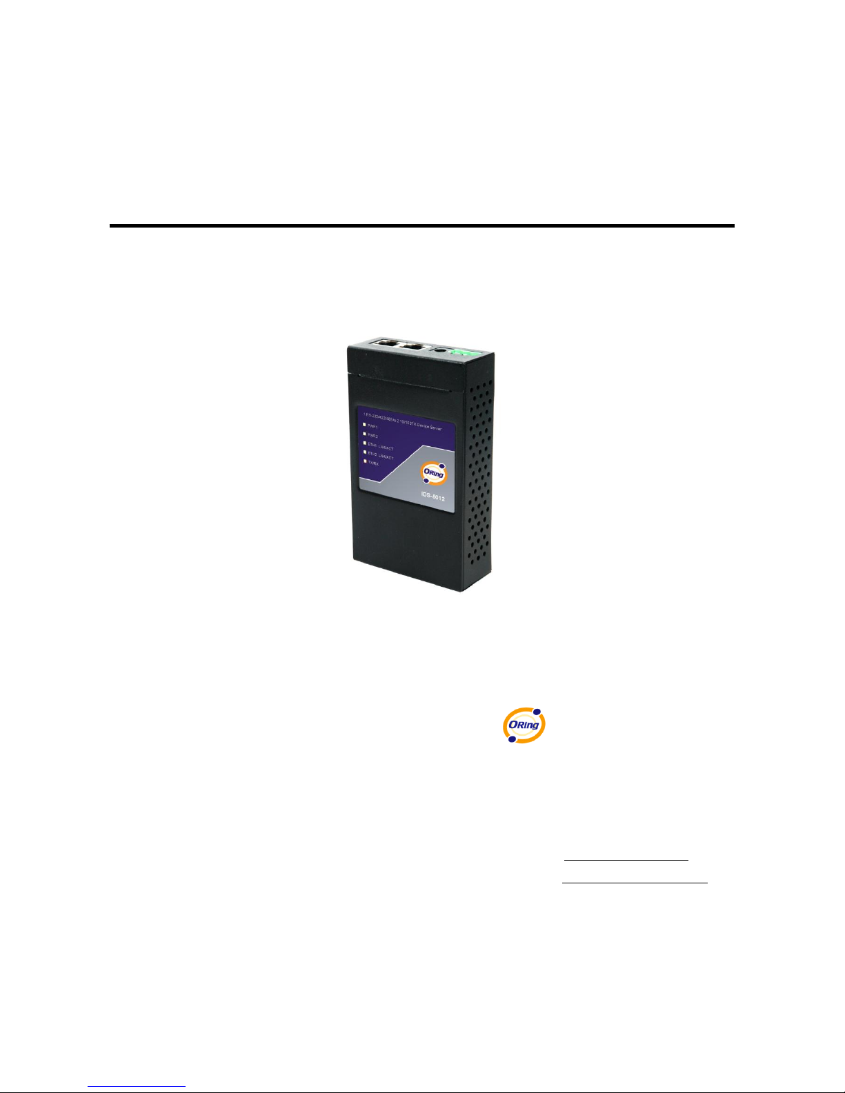
1.1 About the IDS-5012 Serial Device Server
IDS-5012 is an innovative 1 port RS232/422/485 to 2 ports LAN
redundant device server. To assure the agility and security of critical
data, IDS-5012 offers many powerful features for HW & SW redundant
functions. When the connection between master-link and LAN fails,
the IDS-5012 can automatically switch to another LAN port within
10mS, and still guarantees a non-stop connection.
IDS-5012 also supports switch mode, you can use Daisy Chain to
reduce the usage of Ethernet switch ports. Secondly, the IDS-5012
can simultaneously transfer data into 5 host PCs. This feature can
assure all critical data that saved in different host PC to avoid Ethernet break or host PCs
failure. IDS-5012 also Support the data encryption with SSL, so it can assure the data transfer
safely.
Thirdly, the IDS-5012 provides dual redundant power inputs on DC power jack and terminal
block. IDS-5012 also provides NAT pass through function so that you are able to manage
IDS-5012 inside or outside the NAT router. It is easy for different IP domain to use IDS-5012.
You can configure and mange the device server easily by using the windows management tool
(DS-Tool). Therefore, IDS-5012 is the best communication redundant solution for current
application of serial devices
1.2 Software Features
Redundant Dual Ethernet Ports: Recovery time < 10mS

IDS-5012 Series User’s Manual
ORing Industrial Networking Corp 2.
Switch Mode Supported: Daisy Chain support to reduce usage of switch ports
NAT-pass through: User can manage IDS-5012 through NAT router
PPPoE for internet connection.
Data Encryption with SSL for Security data transfer.
DDNS for domain name service.
Redundant Power Inputs: 12~48VDC on power jack and terminal block
Redundant multiple host devices: 5 simultaneous in Virtual COM, TCP Server , TCP Client
mode, UDP
Secured Management by HTTPS and SSH,
Versatile Modes: Virtual Com, Serial Tunnel, TCP Server, TCP Client, UDP
Event Warning by Syslog, Email, SNMP trap, and Beeper
Various Windows O.S. supported: Windows NT/2000/ XP/ 2003/VISTA
1.3 Hardware Features
Redundant Power Inputs: 12~48 VDC on terminal block and power jack
Operating Temperature: -10 to 60
o
C
Storage Temperature: -40 to 85
o
C
Operating Humidity: 5% to 95%, non-condensing
Casing: IP-30
2 10/100Base-T(X) Ethernet port
Dimensions(W x D x H) : 72mm(W)x125 mm(D)x31mm(H)
IDS-5012 Series User’s Manual
3 ORing Industrial Networking Corp.
Hardware Installation
2.1 Install IDS-5012 on DIN-Rail
Each IDS-5012 has a Din-Rail kit on rear panel. The Din-Rail kit helps IDS-5012 to fix on the
Din-Rail. It is easy to install the IDS-5012 on the Din-Rail:
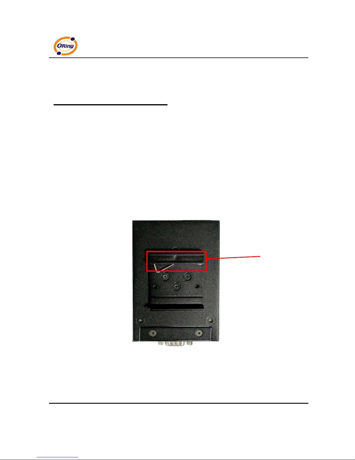
2.1.1 Mount IDS-5012 on DIN-Rail
Step 1: Slant the IDS-5012 and mount the metal spring to Din-Rail.
Figure 2-1
Metal
Spring
IDS-5012 Series User’s Manual
ORing Industrial Networking Corp 4.
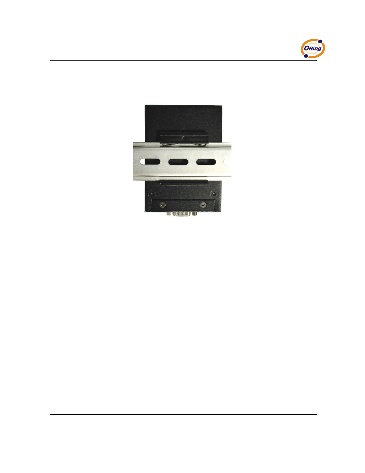
Step 2: Push the IDS-5012 toward the Din-Rail until you heard a “click” sound.
Figure 2-2
2.2 Wall Mounting Installation
Each IDS-5012 has another installation method for you. A wall mount panel can be found in
the package. The following steps show how to mount the IDS-5012 on the wall:
IDS-5012 Series User’s Manual
5 ORing Industrial Networking Corp.
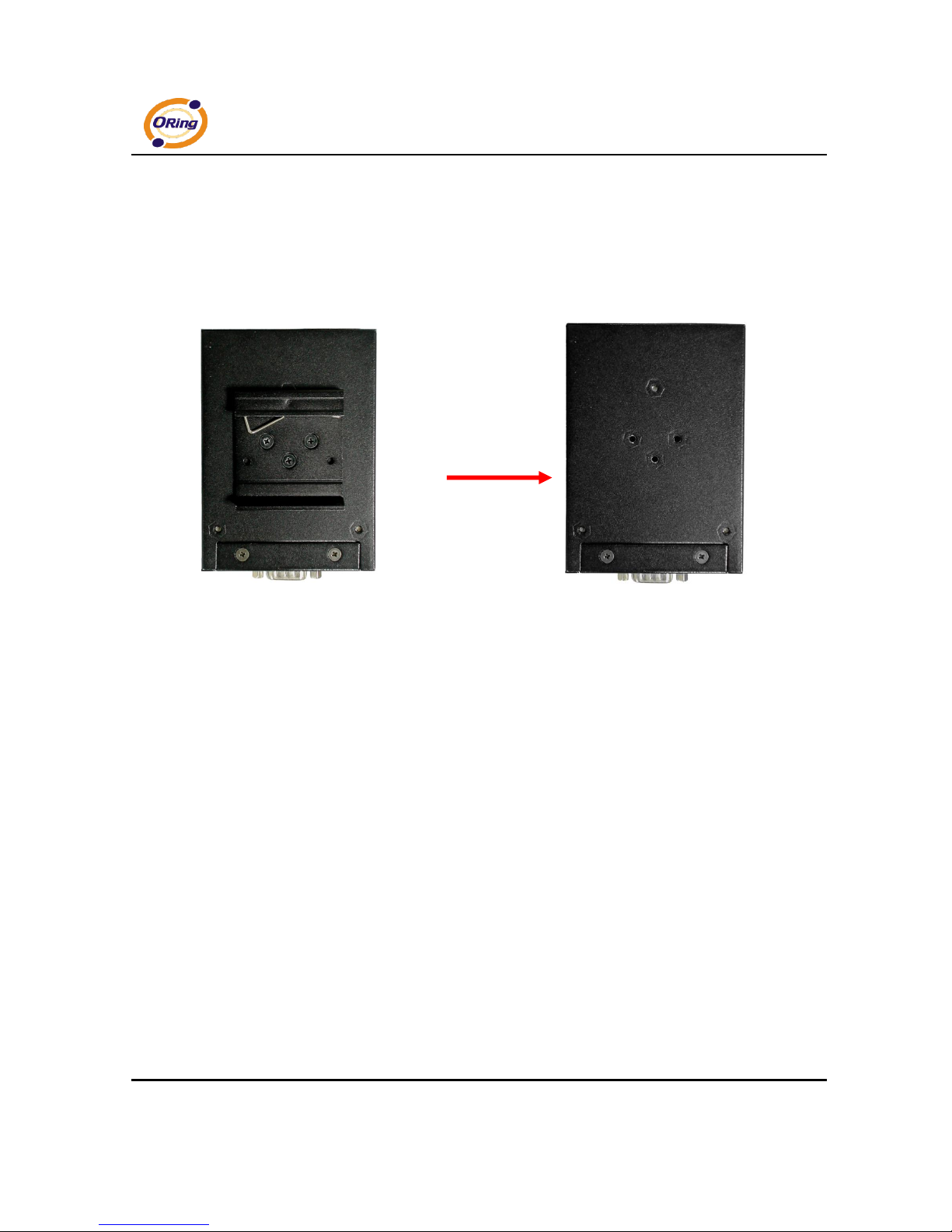
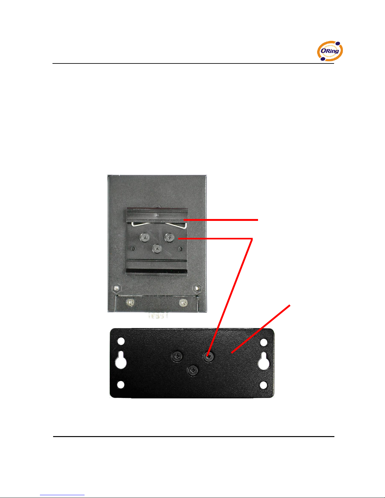
2.2.1 Mount IDS-5012 on wall
Step 1: Remove Din-Rail kit.
Figure 2-3
IDS-5012 Series User’s Manual
ORing Industrial Networking Corp 6.
Pozidrive
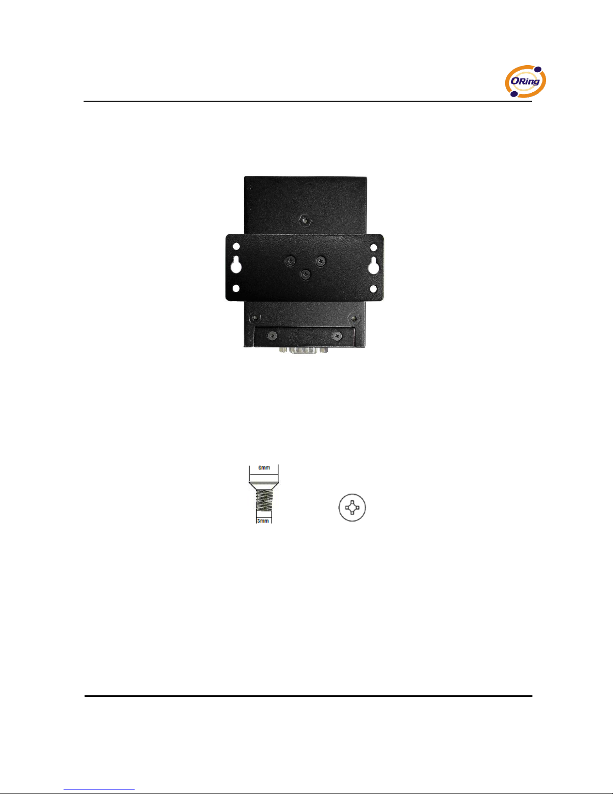
Step 2: Use 6 screws that can be found in the package to combine the wall mount panel.
Just like the picture shows below:
Figure 2-4
The screws specification shows in the following two pictures. In order to prevent IDS-5012
from any damage, the size of screws should not be larger than the size that used in
IDS-5012.
Figure 2-5
IDS-5012 Series User’s Manual
7 ORing Industrial Networking Corp.
Step 3: Mount the combined IDS-5012 on the wall. .
Figure 2-6

IDS-5012 Series User’s Manual
ORing Industrial Networking Corp 8.
Hardware Overview
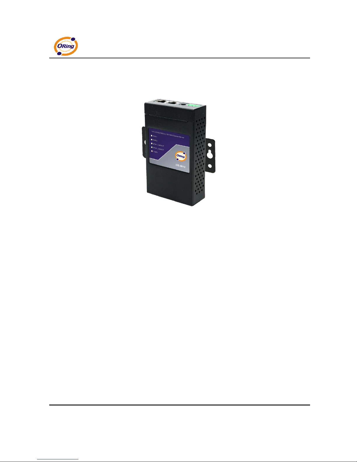
3.1 Front Panel
Figure 3-1
1. Product description of IDS-5012.
2. LED for PWR1 and system status. When the PWR1 links, the green led will be light on.
3. LED for PWR2 and system status. When the PWR2 links, the green led will be light on.
4. LED of 10/100Base-T(X) Ethernet port 1.
5. LED of 10/100Base-T(X) Ethernet port 2.
6. LED of serial port. Green for transmitting, red for receiving
4
3 2 5
6
1

IDS-5012 Series User’s Manual
9 ORing Industrial Networking Corp.
3.2 Front Panel LEDS
The following table describes the labels that stick on the IDS-5012.
LED
Color
Status
Description
PWR1
Green/Red
On
DC power 1 activated.
Red blinking
Indicates an IP conflict, or DHCP or BOOTP
server did not respond properly
PWR2
Green/Red
On
DC power 2 activated.
Red blinking
Indicates an IP conflict, or DHCP or BOOTP
server did not respond properly
ETH1
Green/Amber
Green On/Blinking
100Mbps LNK/ACT
Amber On/Blinking
10Mbps LNK/ACT
ETH2
Green/Amber
Green On/Blinking
100Mbps LNK/ACT
Amber On/Blinking
10Mbps LNK/ACT
Serial
Green
Blinking
Serial port is transmitting data
Red
Blinking
Serial port is receiving data
Table 3-1 Front panel LEDs

IDS-5012 Series User’s Manual
ORing Industrial Networking Corp 10.
3.3 Top Panel
The Top panel components of IDS-5012 are shown as below:
1. Terminal block include: PWR1 (12 ~ 48V DC)
2. Power Jack include: PWR2 (12 ~ 48V DC)
3. RJ45 Ethernet Connector: 2 10/100Base-T(X) Ethernet interface.
Figure 3-2
3.4 Bottom Panel
The bottom panel components of IDS-5012 are shown as below:
Figure 3-3
IDS-5012 Series User’s Manual
11 ORing Industrial Networking Corp.
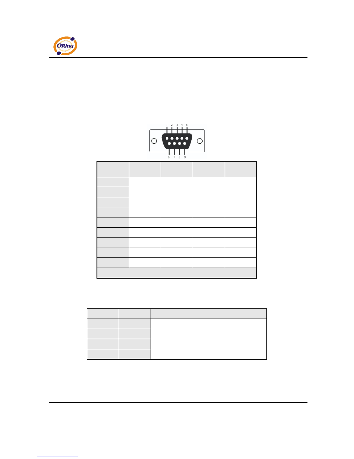
1. Reset button. 5 seconds for factory default.
2. Male DB9 connector: Serial interface of RS-232/422/485 (2 wire)(4 wire).
Pin #
RS 232
RS 422
RS 485
( 4 wire )
RS 485
( 2 wire )
1
DCD
RXD -
RXD -
2 RXD
RXD +
RXD +
3 TXD
TXD +
TXD +
DATA +
4
DTR
TXD -
TXD -
DATA -
5
GND
GND
GND
GND
6
DSR
7 RTS 8
CTS
9
RI
RS 232 mod act as DTE
Table 3-2 Pin assignment
3. DIP Switch: Termination for RS-422/485
DIP 1
DIP 2
Termination Configuration
ON
ON
Termination for long distance 4-wire RS485/422
ON
OFF
Reserved
OFF
ON
Termination for long distance 2-wire RS485
OFF
OFF
No termination for RS485/ 422 (short distance)
Table 3-2 DIP Switch
DB9 connector
IDS-5012 Series User’s Manual
ORing Industrial Networking Corp 12.
3.5 Rear Panel
The rear panel components of IDS-5012 are shown as below:
1. Screw holes for wall mount kit and DIN-Rail kit.
2. Din-Rail kit
3. Wall Mount kit.
Figure 3-4 Rear Panel
1 2 3
IDS-5012 Series User’s Manual
13 ORing Industrial Networking Corp.
Cables
4.1 Ethernet Cables
The IDS-5012 has standard Ethernet ports. According to the link type, the IDS-5012 use CAT
3, 4, 5,5e UTP cables to connect to any other network device (PCs, servers, switches, routers,
or hubs). Please refer to the following table for cable specifications.
Cable
Type
Max. Length
Connector
10BASE-T
Cat. 3, 4, 5 100-ohm
UTP 100 m (328 ft)
RJ-45
100BASE-TX
Cat. 5 100-ohm UTP
UTP 100 m (328 ft)
RJ-45
Table 4-1 Cable Types and Specifications
100BASE-TX/10BASE-T Pin Assignments
With 100BASE-TX/10BASE-T cable, pins 1 and 2 are used for transmitting data, and pins 3
and 6 are used for receiving data.
IDS-5012 Series User’s Manual
ORing Industrial Networking Corp 14.
Pin Number
Assignment
1
TD+
2
TD-
3
RD+
4
Not used
5
Not used
6
RD-
7
Not used
8
Not used
Table 4-2 RJ-45 Pin Assignments
The IDS-5012 supports auto MDI/MDI-X operation. You can use a straight- through cable to
connect PC to IDS-5012. The following table below shows the 10BASE-T/ 100BASE-TX MDI
and MDI-X port pin outs.
Pin Number
MDI port
MDI-X port
1
TD+(transmit)
RD+(receive)
2
TD-(transmit)
RD-(receive)
3
RD+(receive)
TD+(transmit)
4
Not used
Not used
5
Not used
Not used
6
RD-(receive)
TD-(transmit)
7
Not used
Not used
8
Not used
Not used
Table 4-2 MDI / MDI-X pins assignment
Note: “+” and “-” signs represent the polarity of the wires that make up each wire pair.
IDS-5012 Series User’s Manual
15 ORing Industrial Networking Corp.
Management Interface
5.1 DS-Tool
DS-Tool is a powerful Windows utility for DS series. It supports device discovery, device
configuration, group setup, group firmware update, monitoring functions...etc. It is easy for
you to install and configure devices over the network.
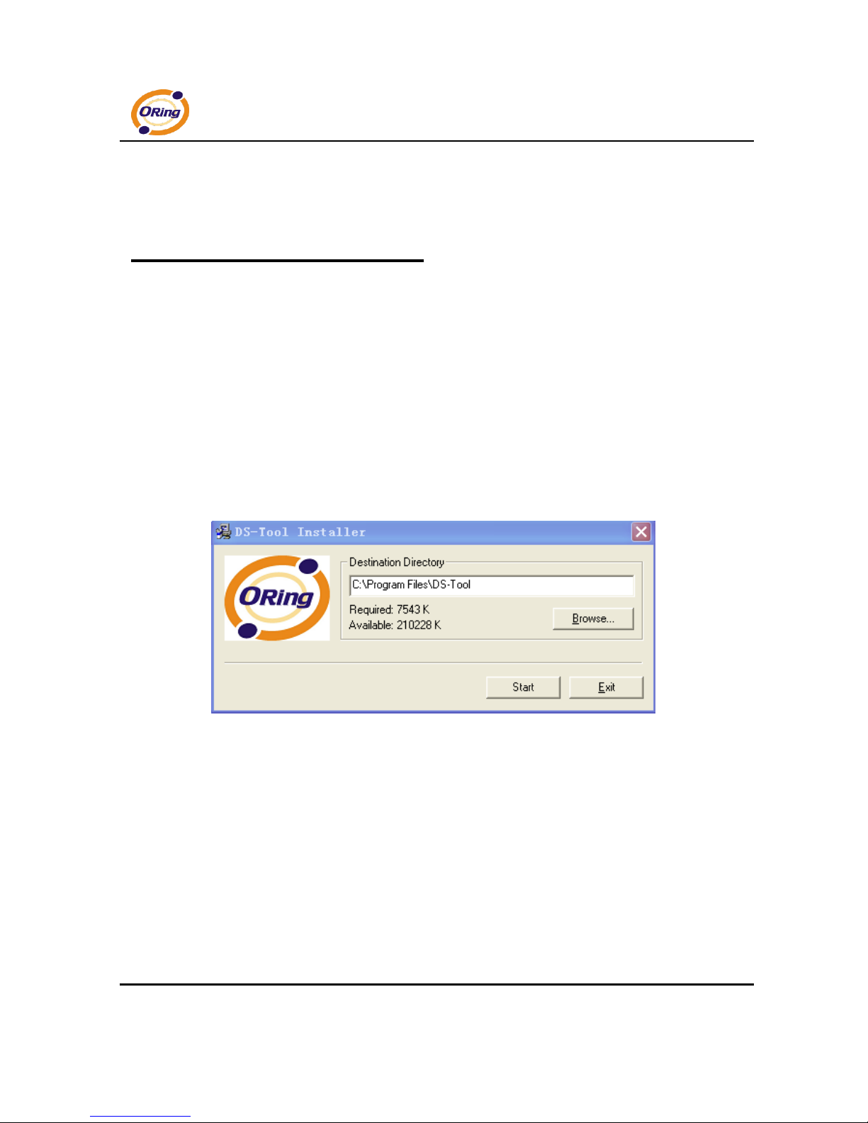
5.1.1 Install IDS-Tool
Step 1: Execute the Setup program, click “start” after selecting the folder for DS-Tool.
Figure 5-1
IDS-5012 Series User’s Manual
ORing Industrial Networking Corp 16.
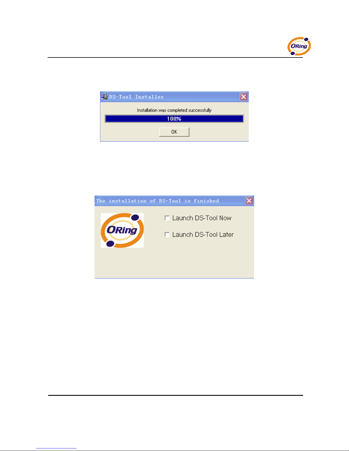
Step 2: When installation complete successfully, then click “OK”.
Figure 5-2
Step 3: Check for your selection.
Figure 5-3
IDS-5012 Series User’s Manual
17 ORing Industrial Networking Corp.
5.1.2 Using DS-Tool
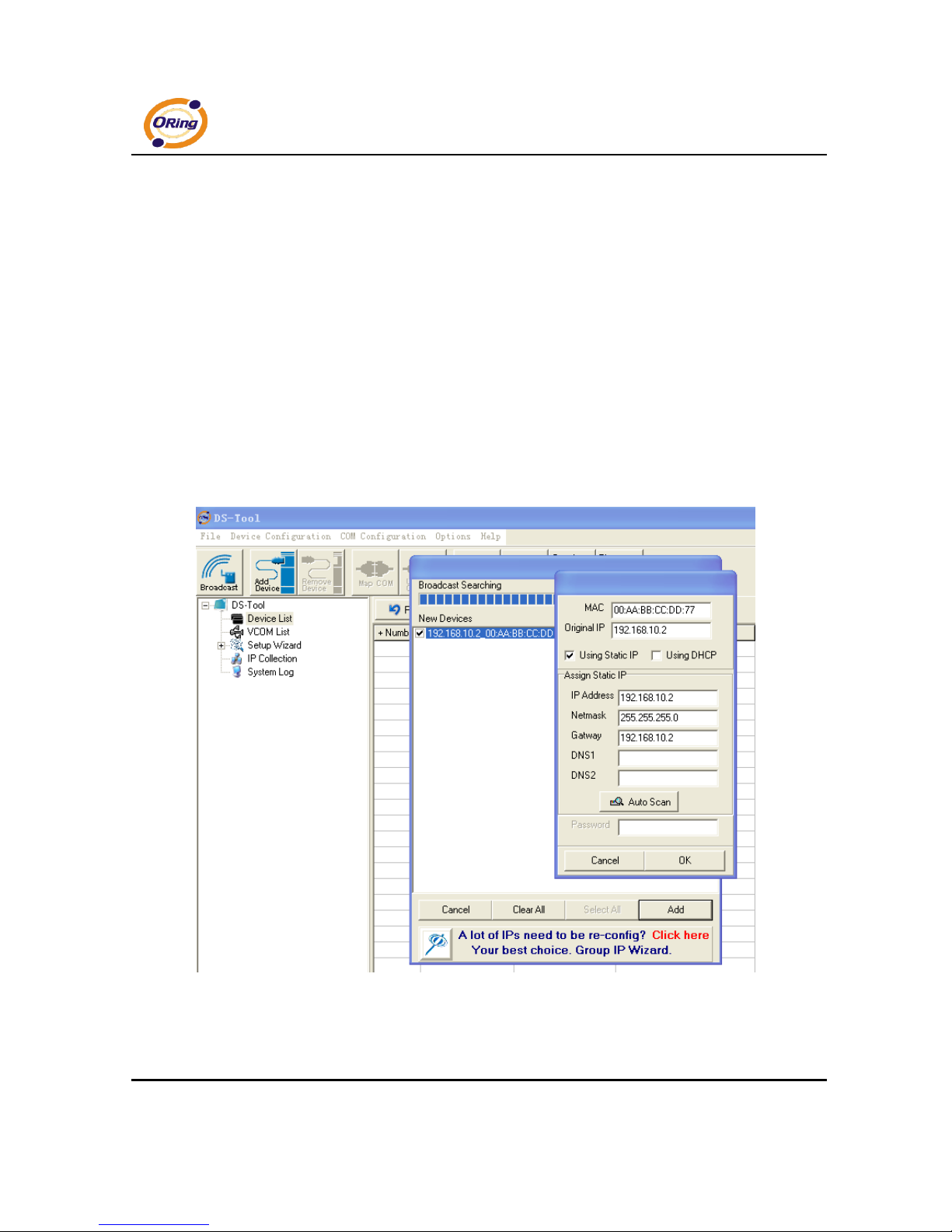
5.1.2.1 Explore device servers
DS-Tool will broadcast to the network and search all available DS devices in the
network. The default IP address of device is “192.168.10.2”, and selects the
searching device you wish to use and press “Add” button.
You can set static IP address or in DHCP client mode to get IP address automatically.
Finally, click “OK “button to add the device.
Figure 5-4
 Loading...