

Origon D62 DT, D64, D66, D62 SUR, D68 Installation Manual
Installation Manual
D62 DT/SUR
D62
D64
D66
D68
Director 60 Collection
Models:

2 1
844·674·4461
TECHSUPPORT@ORIGINACOUSTICS.COM
WWW.ORIGINACOUSTICS.COM
DIRECTOR 60 INSTALLATION MANUAL
Table of Contents
Introduction 1
Installation Requirements and Recommendations 1
What’s included 1
Required Tools/Items 2
Optional Tools/Items 2
Model D60 DT/SUR 3
Dual Tweeters 3
Surround 3
Stereo 3
Speaker Placement 4
Auxiliary Room (2 Speakers) 4
Dedicated Room Home Theater (5 Speakers) 4
Installation 5
1) Installing the Wire 5
2) Painting the Grille 7
3) Cutting the Hole 7
4) Installing the InstaMount 8
5) Connecting the Wires 9
6) Installing the Speaker 9
7) Listening Test and Adjustments 10
8) Installing the Grille 11
Troubleshooting 12
Technical Assistance 13
Specifications 15
Warranty 16
Limited Lifetime Warranty 16
Requirements and Warranty Coverage 17
Return Process 17
What’s included
• Template
• Speaker
• InstaMount (with 4
detachable ZipClips)
• Grille
Pivong
Woofer
InstaMountSpeaker
ZipClips
Locking Tab
Pivong
Tweeter
ZipClip Rails
Figure 1.1: Speaker and InstaMount
Introduction
Thank you for purchasing the Director 60 In-Ceiling Speaker.
At Origin Acoustics, we take pride in providing you with a high
quality product. All of Origin Acoustics’ speakers are designed to
have excellent sound quality, longevity, and a simple installation
process.
This instruction booklet covers the necessary information for a
smooth installation of your Director, including: the tools you will
need, step-by-step instructions for installation, troubleshooting
tips for any errors that may occur, and all warranty information. If
for any reason you experience problems or if you have installation
questions please call us at (844) 674-4461. Hours of operation are
8:00am to 5:00pm (Pacific Time), Monday through Friday.
Installation Requirements
and Recommendations
2 3
844·674·4461
TECHSUPPORT@ORIGINACOUSTICS.COM
WWW.ORIGINACOUSTICS.COM
DIRECTOR 60 INSTALLATION MANUAL
For this setup, use a
multi-stranded wiring designed
for amplifier to speaker connections. The gauge of wire used
can have an impact on the performance of your speakers and
we would recommend that you
choose the largest wire size that
is practical for your installation.
Which gauge to select depends
on the length of wire to be used
on any particular speaker. In
general the shorter the run the
smaller the wire size you can
use, however you can never go
wrong by using a thicker gauge.
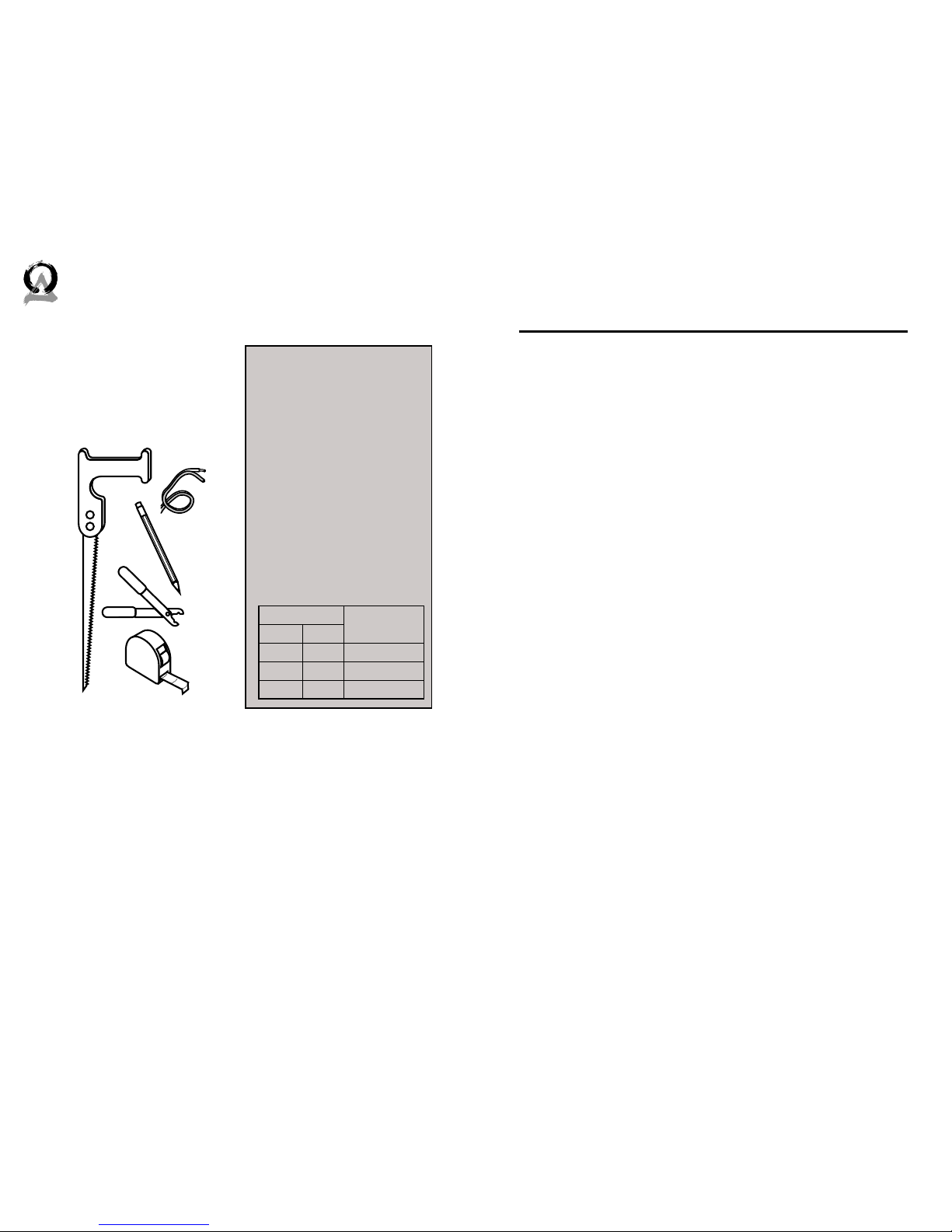
Wire Length Recommend-
ed Gauge
Feet Meter
0-100 0-30 16
50-150 15-45 14
100+ 30+ 12
Speaker Wire
Recommendations
Required Tools/Items
1. Keyhole or drywall saw
2. Speaker wire
3. Pencil
4. Wire stripper
5. Measuring tape
Optional Tools/Items
• Drill with ⅛” (3mm) drill
bit
To check for obstacles in ceiling
• Sti wire (like from a coat
hanger)
To check for obstacles in ceiling
• Stud finder To check for obstacles in ceiling
• Fish tape To route wire through walls
• Can of spray paint For painting the grille
• Can of compressed air For painting the grille
5
4
3
2
1
Figure 2.1: Tools
Model D60 DT/SUR
Dual Tweeters
The Dual Tweeter models can be used for either one channel (surround) or two channels (stereo). A switch is located on the back of
the speaker to select which mode to use. One of the inputs is labeled for surround. This is the input that should be used if you’re
only using one channel.
Surround (Dipole)
In this mode, one channel is fed into both tweeters to be distributed throughout the area. This way in a multiple-speaker setup, one
speaker can be a dedicated le speaker and another a dedicated
right.
Stereo (Bipole)
In this mode, two channels are fed into the speaker: one channel
for each tweeter. This setup is ideal for small rooms such as walkin closets and bathrooms, as well as oddly-shaped areas such as
hallways. With both le and right channels in one speaker, only
one speaker is needed in smaller rooms. Or in areas like hallways,
both channels can be evenly distributed throughout the area with
multiple speakers.
WARNING
If you are using a dual tweeter speaker in stereo mode (i.e. there
are two wires connected to the speaker: one for the le channel
and one for the right), do not set the switch to surround mode.
This could damage the amplifier.
4 5
844·674·4461
TECHSUPPORT@ORIGINACOUSTICS.COM
WWW.ORIGINACOUSTICS.COM
DIRECTOR 60 INSTALLATION MANUAL
Installation
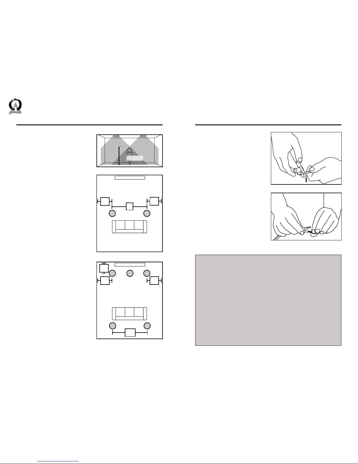
1) Installing the Wire
Strip ¼ to ½ inches (6 to 12
mm) of the insulation o both
ends of the wire. To avoid stray
strands, twist them at the end.
Connect the wire to the amplifier, and make sure the wire
connected to the le speaker
output will be routed to the le
speaker, right output to right
speaker, etc.
You will need a wire that has at least two conductors; one that can be
identified as the positive and the other as the negative. All two conductor
wires have some means of identifying which conductor is which, but at
times this identification may be subtle. It’s crucial that you keep track of
which wire you use for positive (+) and negative (-). Typically if the wires
are colored red and black, the red wire is used for positive and the black
wire is used for negative, but sometimes other colors or patterns are
used. You can choose whichever color of wire you want to be positive and
negative as long as you remain consistent throughout the install.
On both your amplifier and your speaker the connectors will be identified as red for positive and black for negative. It is very important to look
carefully at the speaker wires and be certain that the same wire that is
attached to the positive connector in the amplifier is attached to the positive connector in the speaker.
About Speaker Wire
Figure 5.1: Strip Wire
Figure 5.2: Twist Ends
Speaker Placement
Auxiliary Room (2 Speakers)
Position the two speakers in the
middle of the room, no less than
6’ (2m) apart. Ideally, the two
speakers would be placed an
equal distance from the listener. If
the room has a lower ceiling, the
speakers can be closer together.
Also, if the speaker placement is
intended for standing (as opposed
to sitting) listeners, the speakers
can be closer together. Figure 4.1
shows the sound coverage of the
room.
(The D62 DT/SUR speakers should
be located directly to the side of
the listener, unlike the other models.)
Home Theater (5 Speakers)
The Le Rear (LR) and Right Rear
(RR) speakers should be installed
just behind the listener, one on
either side. The Center Channel
(CC) speaker should be placed
above and slightly in front of the
television, with the Le Front (LF)
and Right Front (RF) speakers
placed equidistant to either side.
Listener
6’
(2m)
Le Speaker Right Speaker
Figure 4.1: Sound Coverage
Listening Area
6’+
2m+
2’-3’
.5-1m
2’-3’
.5-1m
TV
Left
Speaker
Right
Speaker
Figure 4.2: 2 Speaker Setup
Listening Area
6’-10’
2-3m
2’-3’
.5-1m
TV
LF RF
RRLR
CC
2’-3’
.5-1m
2’-3’
.5-1m
Figure 4.3: 5 Speaker Setup
 Loading...