

Page 1
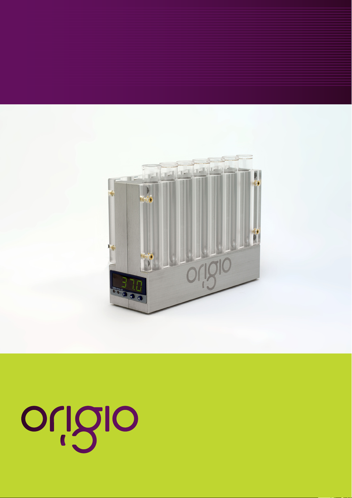
Tube Warmer TW37
User Manual
Page 2
Table of Contents
1. General information . . . . . . . . . . . . . . . . . . . . . 3
2. Product Overview . . . . . . . . . . . . . . . . . . . . . . 4
3. Unpacking the Tube Warmer TW37. . . . . . . . . . . . .5
4. Attention . . . . . . . . . . . . . . . . . . . . . . . . . . . 5
5. Accessories . . . . . . . . . . . . . . . . . . . . . . . . . . 6
5.1 Standard accessories . . . . . . . . . . . . . . . . . . . . . . 6
5.2 Optional equipment . . . . . . . . . . . . . . . . . . . . . . 6
6. User Manual . . . . . . . . . . . . . . . . . . . . . . . . . 7
6.1 Definition of use . . . . . . . . . . . . . . . . . . . . . . . . . 7
6.2 General description . . . . . . . . . . . . . . . . . . . . . . . 7
6.3 Construction of the Tube Warmer TW37 . . . . . . . . . . . 8
6.4 Placing instruments . . . . . . . . . . . . . . . . . . . . . . . 8
6.5 Power supply . . . . . . . . . . . . . . . . . . . . . . . . . . 8
6.6 Start up. . . . . . . . . . . . . . . . . . . . . . . . . . . . . . 9
7. User maintenance . . . . . . . . . . . . . . . . . . . . . 10
7.1 Cleaning . . . . . . . . . . . . . . . . . . . . . . . . . . . . 10
7.2 Technical support and guarantee . . . . . . . . . . . . . . 10
8. Changing the Set point . . . . . . . . . . . . . . . . . . 11
9. Calibration . . . . . . . . . . . . . . . . . . . . . . . . . 11
9.1 Password Entry . . . . . . . . . . . . . . . . . . . . . . . . 11
9.2 Temperature calibration . . . . . . . . . . . . . . . . . . . 12
9.3 Re-Enter Password protection . . . . . . . . . . . . . . . . 13
9.4 Auto Tune procedure . . . . . . . . . . . . . . . . . . . . . 13
10. Standard settings Value Parameters . . . . . . . . . . . 14
11. Technical data . . . . . . . . . . . . . . . . . . . . . . . 15
11.1 Dimensions . . . . . . . . . . . . . . . . . . . . . . . . . . 15
11.2 Power Supply. . . . . . . . . . . . . . . . . . . . . . . . . 15
2
Page 3
1. General information
COPYRIGHT
This manual contains information that is subject to copyright. All rights reserved. This
manual should not be photocopied, otherwise copied or distributed, completely or in
part, without the approval of ORIGIO ScanLab Equipment a/s
Users of ORIGIO’s products should not hesitate to contact us if there are any errors,
unclear points or ambiguities in this manual.
ORIGIO ScanLab Equipment a/s
Knardrupvej 2
2760 Måløv
Denmark
Tel.: +45 45 99 56 00
Fax: +45 45 99 56 19
E-mail: [email protected]
Internet: www.origioscanlab.com
Document No: User Man_TW37
Version no: Version 1
Date: October 2011
This instrument is constructed to comply with IEC requirements.
3
Page 4
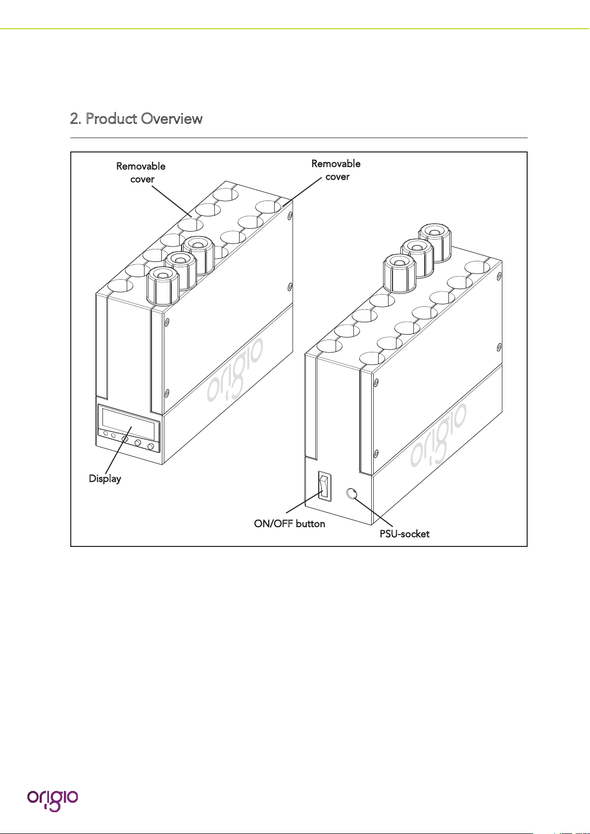
2. Product Overview
Removable
cover
Removable
cover
Display
ON/OFF button
PSU-socket
4
Page 5
3. Unpacking the Tube Warmer TW37
• Unpack the equipment.
• Check the packing list to ensure all accessories are there.
• Examine the packing material carefully for separetely packed items.
• Check the Tube Warmer TW37 for external surface damage.
• Check that the display is not broken or damaged.
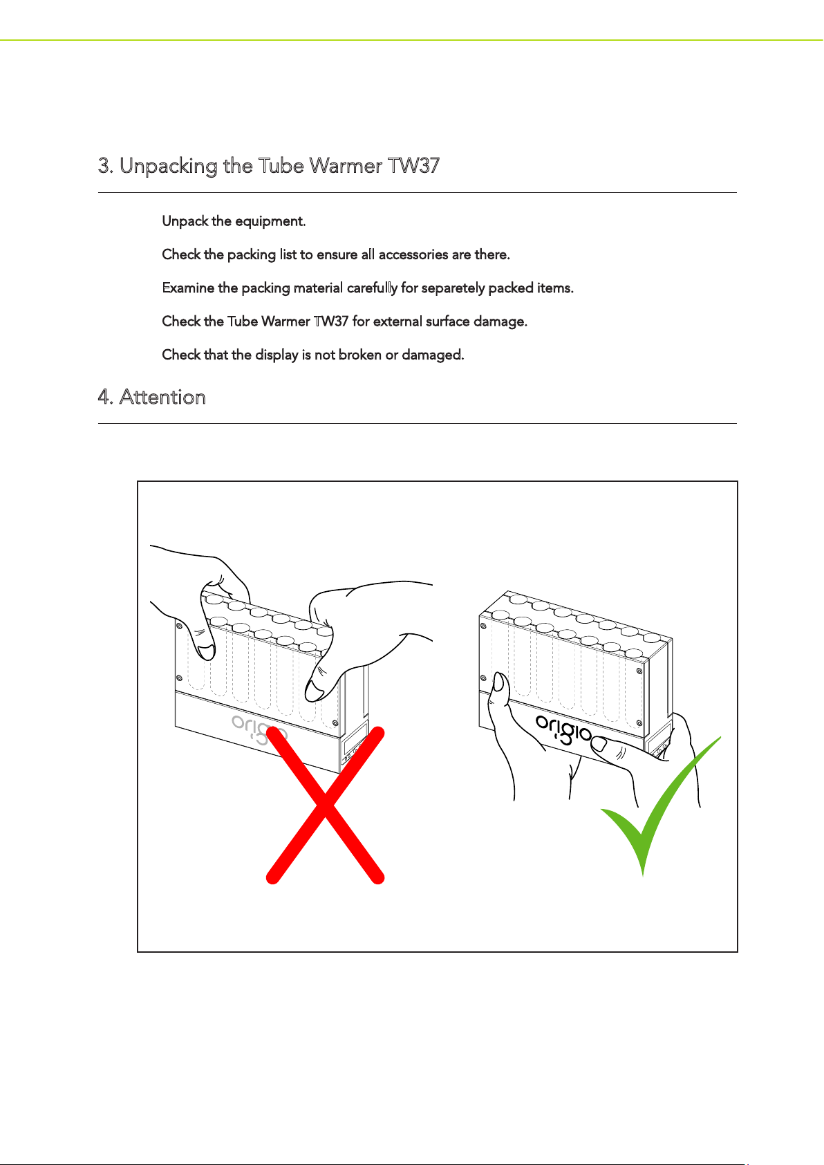
4. Attention
Do NOT carry the Tube Warmer TW37 by the polycarbonate side panels
5
Page 6
5. Accessories
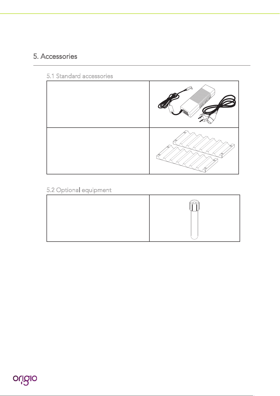
5.1 Standard accessories
24 volts main adapter (PSU) and mains
cable
Item number: 9001701802
Side panels
Item number: 9001701803 (2 off)
5.2 Optional equipment
14 ml round bottom tube
Nunc item number: 1050268
Falcon item number: 2057
6
Page 7

6. User Manual
6.1 Definition of use
The Tube Warmer TW37 is designed to warm up and maintain test tubes at a constant
temperature.
6.2 General description
The unit is able to hold up to 14 test tubes, type 14 ml round bottom tubes, 7 on each
side. Sterile test tubes are placed in one of the 14 slots on the unit to maintain a constant
temperature or to warm up with the unit.
The 4 character green LED display will indicate the current temperature of the Tube
Warmer TW37. Adjustments to the temperature can be made using the up and down
arrow keys.
K1 K2
7
Page 8

The sides of the Tube Warmer TW37 can be removed for sterilising and general cleaning.
6.3 Construction of the Tube Warmer TW37
The unit is constructed of an anodised Aluminium casing containing the internal control,
power input and heating system for the tubes.
A removable polycarbonate front on either side of the unit ensures that the tube remain
in place whilst in use. The unit must be connected to mains power, for normal operation
mode.
The casing design is also made to retain and maintain the heat to an even level and
avoid high fluctuations in temperature.
Two polycarbonate front panels are magnetically fixed to the front, for visual indication of
filled tubes and removable for ease of cleaning.
6.4 Placing instruments
Place the Tube Warmer TW37 on a flat surface, away from heat and direct sunlight.
6.5 Power supply
Put the power supply in connector on the back of the Tube Warmer TW37. Then connect
the power supply to power mains.
Note Use only the power cord supplied with the Tube Warmer TW37, un-approved
power supplies may damage the unit and invalidate the warranty.
8
Page 9
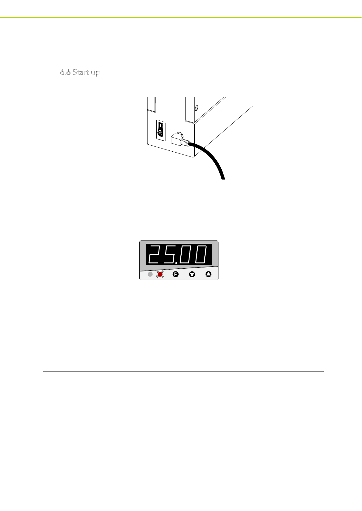
6.6 Start up
Press on/off button on the back of the Tube Warmer TW37.
The display and lights K1 (led) and K2 (led) will start flashing, after 3 seconds the actual
temperature will appear on the display. At this point the Tube Warmer TW37 will
automatically begin to warm up to the set point temperature.
This is indicated by the led K2 flashing.
K1 K2
The temperature will reach 36-37° degrees within 8 minutes, but true stabilisation of the
temperature will take approximately 60 minutes. When the temperature is stabilised, the
Tube Warmer TW37 is ready for use.
Caution It is important at this point that none of the settings should be changed.
Note After each use, remove the power supply from the connection at the rear side.
9
Page 10
7. User maintenance
7.1 Cleaning
Main body of Tube Warmer TW37 is to be cleaned with soft lint free cloth soaked with
hot water. (add mildly acidic, neutral or mildly alkaline detergents, if necessary).
Caution Do not use any abrasive cleaning agents or high pressure cleaners and
DO NOT autoclave
Note The Tube Warmer TW37 has limited resistance to organic solvents
(eg. Sprits, benzol etc..)
The Polycarbonate removable side panels are to be cleaned with approved (for IVF)
cleaning and decontamination material, but not abrasive cleaning material.
Caution The Polycarbonate side panels can NOT be Autoclaved
7.2 Technical support and guarantee
In case of malfunction contact ORIGIO custumer support for service support.
Caution Do not open the Tube Warmer TW37 or remove the identification label, this will
invalidate the guarantee.
Note The Tube Warmer TW37 is guaranteed for 24 month from the date of purchase.
10
Page 11

8. Changing the Set point
Ensure the unit is switched on and the current temperature is indicated on the display.
Action Button Display
Press
Programmed temperature ie. 36.5
To change Values press
To save exit press buttons
Note When in the settings menu if a button is not pressed within 5 sec. the menu will
jump back to the normal operational display (with temp. 37.0)
Changes to value
required
Current temperature ie 37.0
9. Calibration
To Calibrate the Tube Warmer TW37 it is important to put in the password to enable
critical data change.
9.1 Password Entry
In the normal operational mode (Display temp. 37.0)
Action Button Display
Press and hold for 5 seconds
(Display will flash between)
By using arrow up and down type in
0000
Exit by pressing for a few seconds
(Back to normal display mode ie. 37.0)
The unit is now ready for accessing the Calibration menu
11
Page 12

9.2 Temperature calibration
The following steps are followed for temperature calibration.
Action Button Display
Press and hold for 5 seconds
(Display will flash between)
Press Slowly 6 times
(Display will flash between)
Press and hold for 5 seconds
(Display will flash between)
Press slowly 11 times
(Display will flash between)
By using arrow up and down type in new
off set value
Press
(Back to normal display mode ie. 37.0)
12
Page 13

9.3 Re-Enter Password protection
Action Button Display
Press and hold for 5 seconds
(Display will flash between)
By using arrow up and down type in new
off set value
Confirm by pressing
(Back to normal display mode ie. 37.0)
The unit is now return to the normal display
9.4 Auto Tune procedure
This procedure is only used when the Tube Warmer TW37 is first powered up from cold.
Externally (with another thermometer) measure the temperature of the unit and follow
the Auto tune procedure below.
Action Button Display
Press and hold for 5 seconds
To exit press
(Back to normal display mode ie. 37.0)
The unit is now return to the normal display
13
Page 14

10. Standard settings Value Parameters
This information is only for setting up the controller should it have to be reset due to
failure, the data is not for general user setting.
Display Text Value Number
Pb 0.3
DT 4
RT 19
CY.1 4.0
HIS 1.0
Y.0 0
Y1 100
Y2 -100
DF 1.4
C111 005
C112 1
C113 10
C114 7
C115 0
C116 0
C117 0
C118 3
C120 0
SPL 0
SPH 50
OFF.S -2.5
AL 999.9
HIST 1
TUNE
2 seconds
14
Page 15

11. Technical data
11.1 Dimensions
Tube Warmer TW37 - External dimensions
Tube Warmer TW37 - Weight 1.5 kg
Tubes Height 95 mm - Diameter 18 mm
Power Supply cable length - to Tube
Warmer TW37
Power Supply cable length - to External 1900 mm approximate
Height 119 mm - Width 52 mm -
Length 174 mm
1600 mm approximate
11.2 Power Supply
The unit is supplied with a Switch mode regulated power supply.
AC input: 100-240 V AC 50/60 Hz
DC output: 7 output selections: 15/16 V DC 8.5 A
18/19 V DC 8 A
20 V DC 7.5 A
22 V DC 6.5 A
24 V DC 6 A
15
 Loading...