

Page 1
- 1 -
OriginIoT EVK User Guide Rev. 1.1 5.13.18
OriginIoT ORG2101 - EVK
O r i g i n GPS. c o m
USER GUIDE
Page 2

- 2 -
OriginIoT EVK User Guide Rev. 1.1 5.13.18
INDEX
1. SCOPE ........................................................................................................................................................... 5
2. DISCLAIMER ............................................................................................................................................... 5
3. SAFETY INFORMATION ............................................................................................................................ 5
4. ESD SENSITIVITY ....................................................................................................................................... 5
5. CONTACT INFORMATION ........................................................................................................................ 5
6. RELATED DOCUMENTATION .................................................................................................................. 5
7. REVISION HISTORY ................................................................................................................................... 6
8. ABOUT ORIGINIOT™ ................................................................................................................................ 6
8.1. MODULE DESCRIPTION ........................................................................................................... 6
8.2. ARCHITECTURE ....................................................................................................................... 6
8.3. ORIGINIOT EVK KIT INCLUDING ............................................................................................... 7
8.4. COMPONENTS ON THE EVK .................................................................................................... 7
9. GETTING STARTED ................................................................................................................................... 7
9.1. REQUIRED EQUIPMENT .......................................................................................................... 7
9.2. CONNECTING THE EVK TO PC VIA DEBUG PORT ...................................................................... 8
10. CONNECTING ORIGINIOT TO A SERVER ....................................................................................... 12
10.1. CELLULAR NETWORK PARAMETERS .................................................................................. 12
10.2. ATTRIBUTING ORIGINIOT TO A SERVER ............................................................................. 12
10.3. ENTERING CELLULAR-NETWORK PARAMETERS – GSM/LTE AUTHENTICATION COMMAND 13
11. ORIGINIOT WEB APPLICATION ....................................................................................................... 15
11.1. OVERVIEW ........................................................................................................................ 15
11.2. USER LOG IN ..................................................................................................................... 15
11.3. WEB HOME TAB ............................................................................................................... 15
11.4 MODULE DETAILS TAB .............................................................................................................. 16
11.5 ADDING A NEW COMMAND ..................................................................................................... 18
Page 3

- 3 -
OriginIoT EVK User Guide Rev. 1.1 5.13.18
11.6 ADDING A CUSTOM COMMAND ............................................................................................... 18
11.7 WIDGET PREVIEW TAB ............................................................................................................. 19
11.8 WIDGET CONGIFURATION ........................................................................................................ 20
11.9 PROFILE TAB ............................................................................................................................ 20
12. OPERATING THE SENSORS ON THE EVK ....................................................................................... 21
12.1 PARAMETER SETUP .................................................................................................................. 21
12.2 ACTIVATING THE SENSORS ....................................................................................................... 22
12.2 WIDGET CONFIGURATION ........................................................................................................ 24
13. ORDERING INFORMATION ................................................................................................................ 25
APPENDIX A – PORTS AND POWER .............................................................................................................. 25
APPENDIX B – FIRMWARE UPLOAD (FLASHING) FOR ORIGINIOT MODULE .................................... 28
APPENDIX C –REGISTER MAPS FOR SENSORS.......................................................................................... 33
APPENDIX D – WORK WITH ORG2101 ADD-ONS........................................................................................ 35
D.1 Using Add-on via connectors J3 and J4 ....................................................................................... 36
D.2 Using Add-on via FFC connector J6............................................................................................. 37
FIGURE INDEX
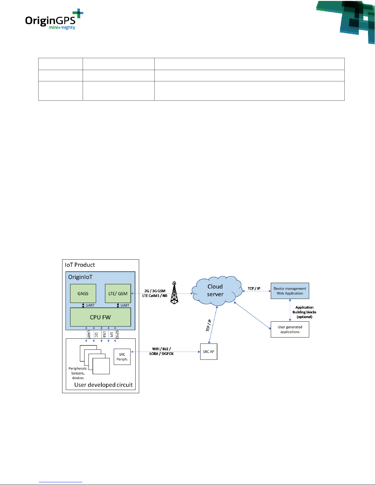
Figure 1 –OriginIoT Architecture ................................................................................................................ 6
Figure 1 – connection of ORG2101 antennas and SIM card ........................................................................ 8
Figure 2 – mating ORG2101 to EVK correctly.............................................................................................. 9
Figure 3 – powering up EVK and ORG2101 ............................................................................................... 10
Figure 3a – Serial port in Tera Term ......................................................................................................... 11
Figure 3c – OriginIoT connected to Debug Console .................................................................................. 12
Figure 6 – OriginIoT Web Application, login page ..................................................................................... 15
Figure 7 – OriginIoT Home Tab ................................................................................................................. 16
Figure 8 – Module Details Tab.................................................................................................................. 16
Figure 8 – Command details .................................................................................................................... 17
Figure 9 – New Command ........................................................................................................................ 18
Figure 9 – Command details .................................................................................................................... 19
Page 4
- 4 -
OriginIoT EVK User Guide Rev. 1.1 5.13.18
Figure 10 – Widget preview tab ............................................................................................................... 19
Figure 10 – Widget configuration window................................................................................................ 20
Figure 11 – Profile Tab ............................................................................................................................. 20
Table 4 – Configuration for I2C Messages ................................................................................................ 22
Table 5 – Configuration for UART Messages ............................................................................................. 23
Table 7: list of orderable parts ................................................................................................................. 25
Figure 32 –J5 connector ........................................................................................................................... 27
Figure 33: ST-Link plug orientation ........................................................................................................... 28
Figure 34: Wire Colors on J7 connector pins ............................................................................................ 29
Figure 35: Power set up for FW upload .................................................................................................... 30
Figure 36: STM32 ST-Link Utility............................................................................................................... 31
Figure 37: Connecting to module in STM32 ST-Link Utility........................................................................ 31
Figure 38: Program & Verify in STM32 ST-Link Utility ............................................................................... 32
Figure 40: Successful Firmware Download ............................................................................................... 33
Figure 41 – mating Add-on to EVK correctly ............................................................................................. 36
Figure 42 – mating Add-on to ORG2101 correctly .................................................................................... 37
Figure 43 – attaching FFC cable to add-on ................................................................................................ 38
Figure 43 – attaching FFC cable to EVK ..................................................................................................... 39
Page 5

- 5 -
OriginIoT EVK User Guide Rev. 1.1 5.13.18
1. SCOPE
This document is a user guide for miniature cellular IoT system evaluation kit (OriginIoT-EVK).
2. DISCLAIMER
All trademarks are properties of their respective owners.
Performance characteristics listed in this document do not constitute a warranty or guarantee of
product performance. OriginGPS assumes no liability or responsibility for any claims or damages arising
out of the use of this document, or from the use of integrated circuits based on this document.
OriginGPS assumes no liability or responsibility for unintentional inaccuracies or omissions in this
document.
OriginGPS reserves the right to make changes in its products, specifications and other information at any
time without notice.
OriginGPS reserves the right to conduct, from time to time, and at its sole discretion, firmware upgrades.
As long as those FW improvements have no material change on end customers, PCN may not be issued.
OriginGPS navigation products are not recommended to use in life saving or life sustaining applications.
3. SAFETY INFORMATION
Improper handling and use can cause permanent damage to the product.
4. ESD SENSITIVITY
This product is ESD sensitive device and must be handled with care.
5. CONTACT INFORMATION
Support - [email protected] or Online Form
Marketing and sales - [email protected]
Web – www.origingps.com
www.origin-iot.com
6. RELATED DOCUMENTATION
№
DOCUMENT NAME
1
ORG2101 Datasheet
2
OriginSmart™ API specifications
3
OriginIoT debug console user guide
4
Spider and Hornet - NMEA Protocol Reference Manual
5
Spider and Hornet - One Socket Protocol Reference Manual
6
Spider and Hornet – OSP GNSS Extension Reference Manual
TABLE 1 – RELATED DOCUMENTATION
Page 6
- 6 -
OriginIoT EVK User Guide Rev. 1.1 5.13.18
7. REVISION HISTORY
REVISION
DATE
CHANGE DESCRIPTION
1.0
March 26, 2018
First Edition – Preliminary
1.1
May 13, 2018
New web application guidance. Mating cycles of connectors. Change in
P/n. Minor corrections and clarifications
TABLE 2 – REVISION HISTORY
8. ABOUT ORIGINIOT™
8.1. MODULE DESCRIPTION
The OriginIoT module ORG2101 is a miniature generic cellular IoT system with GNSS tracker and
interfaces to peripheral sensors and devices. The data is transferred via cellular communication, stored
in a remote server (cloud), and displayed on a web GUI.
The module is communicating through GSM or LTE interface with a cloud-based application.
The multi-purpose IoT sensor platform can accommodate sensors and other peripheral devices via
UART, SPI, I2C, USB, ADC or GPIO, with superior positional accuracy of stand-alone GNSS. Data is
configured over a web interface, eliminating additional embedded FW efforts. The ease and flexibility of
adding the mini+mighty OriginIoT to a vast array of applications quickens time to market while
minimizing the size of your IoT sensor device.
8.2. ARCHITECTURE
Figure 1 –OriginIoT Archite cture
Page 7

- 7 -
OriginIoT EVK User Guide Rev. 1.1 5.13.18
8.3. ORIGINIOT EVK KIT INCLUDING
• OriginIoT ORG2101 module and EVK
• GNSS antenna 12x12x4.3 mm with W.FL connector
• Penta-band GSM antenna with SMA connector (designed to support of all frequency bands, may
be varied upon customer application)
• SMA to U.FL connector cable
• Power adapter
• Micro USB cable
• OriginIoT add-on with EVK sensors, DC/DC and charging circuit (optional)
8.4. COMPONENTS ON THE EVK
• Sensors:
o Accelerometer- ADXL345, U1, by Analog Devices.
Datasheet: http://www.analog.com/media/en/technical-documentation/data-
sheets/ADXL345.pdf
o Gyroscope- DM00168691, U5, by STMicro Electronics.
Datasheet:http://www.st.com/content/ccc/resource/technical/document/datasheet/e4
/b1/d1/62/1a/e6/44/2f/DM00168691.pdf/files/DM00168691.pdf/jcr:content/translatio
ns/en.DM00168691.pdf
o Electronic Compass- IST8304, U3, by iSentek.
Datasheet: http://www.isentek.com/cn/dlf.php?file=../ISENTEK/%28201703-
13%29IST8304%20Datasheet%20v2.3_brief.pdf
o Digital Temperature- TMP104, U4, by Texas Instruments. Datasheet:
http://www.ti.com/lit/ds/symlink/tmp104.pdf
• FTDI to USB serial chip: FT232RQ, U21.
• Voltage Translator 4bit bi-directional: LSF0204PWR, U2.
• Common mode filter for USB/HDMI: ACM2010-900-2p-T002, U23.
• Buck-Boost Switching Regulator IC Positive Adjustable 1.8V 1 Output 3A: LTC3113IDHD#PBF,
U24
• Power Switch ICs- Power Distribution Single 1A Current-Limited, TPS2051B, U25
• 1A Low Noise Fast Transient Response Low Dropout Regulator, TPS3801DCQR
9. GETTING STARTED
9.1. REQUIRED EQUIPMENT
Items needed:
• OriginIoT EVK
• Nano SIM card with data package
• Server with a fixed IP.
Page 8
- 8 -
OriginIoT EVK User Guide Rev. 1.1 5.13.18
OriginIoT module allows the user to communicate with GNSS receiver and sensors through web
GUI on a cloud. The communication between OriginIoT and the cloud server is done through
cellular network via data sim card. OriginGPS provides a cloud server for evaluation:
http://18.184.85.107*
* Server IP can be changed in the future. Please make sure you downloaded the latest
publication of this document from www.origingps.com
• PC with a terminal emulator (such as free – open source Tera-Term)
Tera Term can be downloaded here:
http://download.cnet.com/Tera-Term/3000-20432_4-75766675.html
• Micro USB cable (included in the EVK kit)
9.2. CONNECTING THE EVK TO PC VIA DEBUG PORT
In order to configure the OriginIoT to connect to GSM/LTE Network and web server, it is needed to
configure the module using DEBUG port connection to PC (J22).
Please follow these steps:
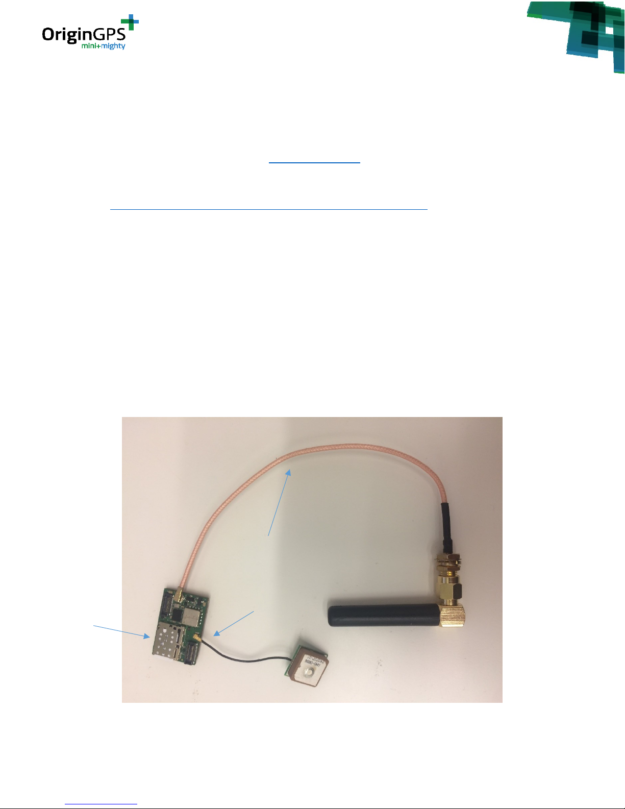
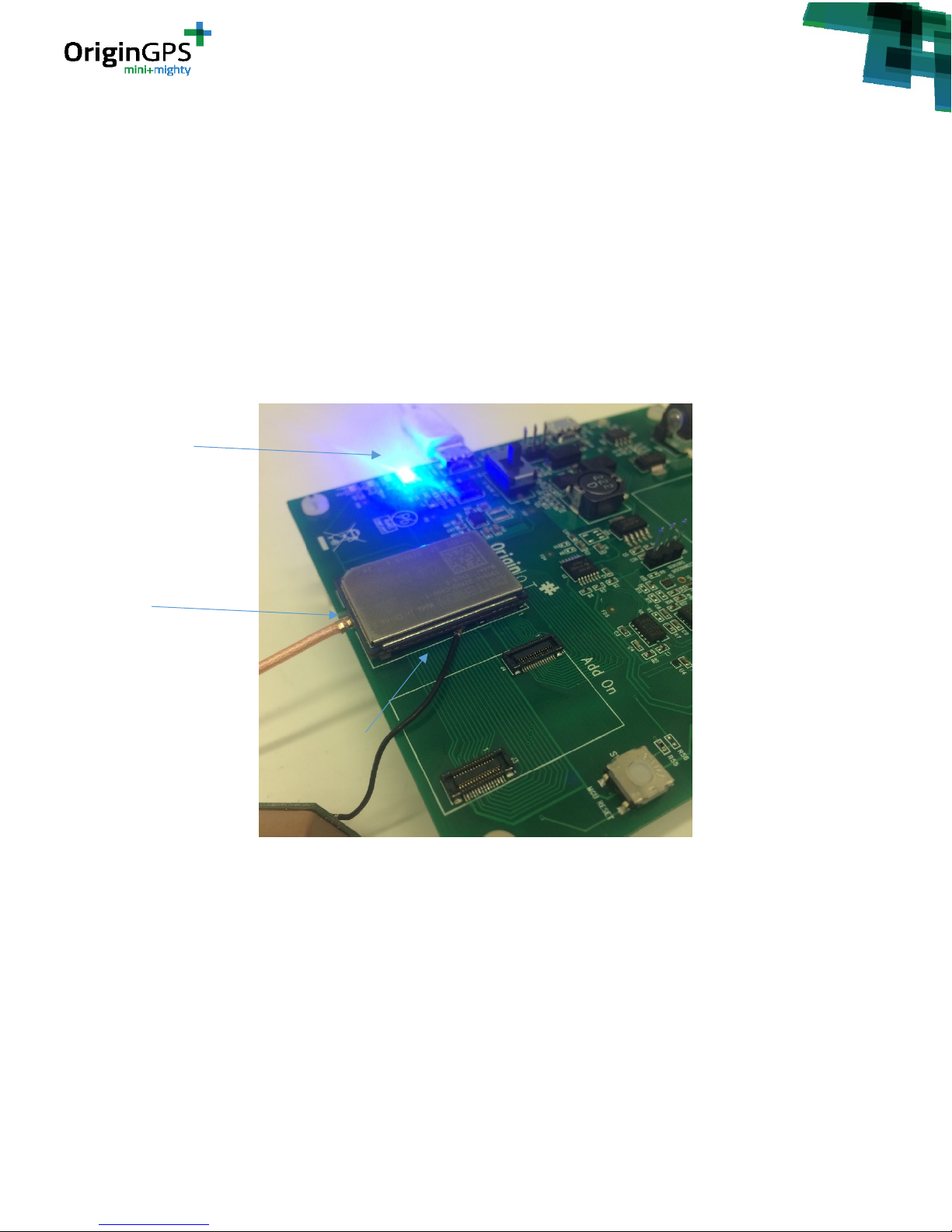
1. Insert nano SIM card to its slot. See figure 1.
Note: skip this step if using ORG2101-XXXX-E (embedded SIM)
2. Connect GSM/LTE antenna to the U.Fl connector OriginIoT, See figure 1.
3. Connect GNSS antenna to the W.Fl connector on OriginIoT, See figure 1. (Required only if user wants
to evaluate GNSS functionality)
Figure 1 – connection of ORG21 01 antennas and SIM card
Cellular Antenna
Nano SIM Card
Slot
GNSS Antenna
Page 9
- 9 -
OriginIoT EVK User Guide Rev. 1.1 5.13.18
4. The OriginIoT module should be connected to EVK board up-side down (components’ side down) to
the area near the OriginIoT logo on the EVK, see figure 2.
Please notice: connection of OriginIoT to EVK is unidirectional – J1 of the module (closer to MCU) should
connect to J1 on the EVK.
Note: Extra precaution is required upon insertion / withdrawal of ORG2101 to EVK. Incautious handling
can alter the performance of the connectors.
You know that you are connected correctly if:
1. J4 for U.FL antenna fits inside its socket on the EVK
2. OriginIoT fits in white outlines drawn on the EVK (silk screen)
Figure 2 – mating ORG2101 to EVK correctly
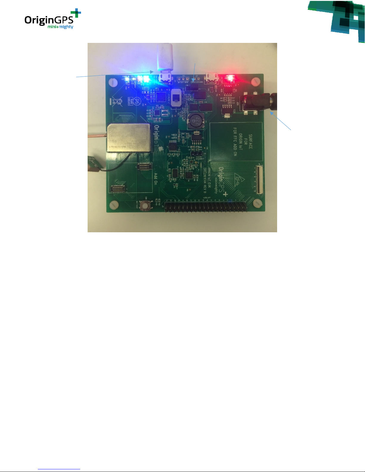
5. Connect USB Power/Console of the EVK to PC via micro USB cable (J22). See figure 3.
6. Supply power to EVK - Connect the power adapter to the EVK (J26). See figure 3.
ORG2101 drawn
outline on silk
screen
J4 with GSM
antenna fits in its
socket
USB cable
connected to J22
Page 10
- 10 -
OriginIoT EVK User Guide Rev. 1.1 5.13.18
Figure 3 – powering up EVK and ORG2101
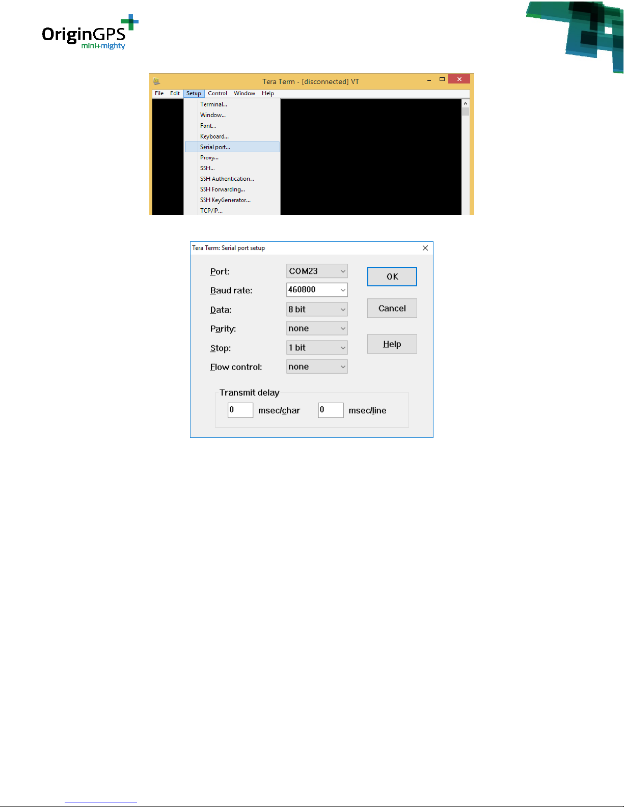
7. Open terminal on your PC and connect to corresponding COM port of the OriginIoT with a baud rate
of 460800 bps.
In Tera Term – go to Setup - > Serial Port (See figure 3a), select the COM port and set baud rate to
460800 bps. Press “OK”. See figure 3b.
Full communication parameters:
• Baud Rate: 460800
• Data Bits: 8
• Stop Bits: 1
• Flow Control: None
• Parity: None
USB connector to
PC via J22
EVK powered by
external 6V
power supply
Jumper J24 selection of
ORG2101 power by 6V plug
Page 11
- 11 -
OriginIoT EVK User Guide Rev. 1.1 5.13.18
Figure 3a – Serial port in Tera Term
Figure 3b – COM settings in Tera Term
8. Supply power to OriginIoT via DC/DC circuit by placing jumper J24. See figure 3.
Note: the EVK can be powered by USB (J22) or Plug (J26) determined by jumper J24.
Note: you can choose one of two DC/DC circuits provided on the EVK – one by Texas Instruments
TPS63070 or one by Linear Technology LTC3113. To switch between them use slide switch J30
After supplying power to OriginIoT you should see a welcome message and GSM/LTE start-up messages.
8. While connected, press Enter key in the terminal.
You should see the command line “ORG>” in the terminal window. See Figure 3c.
Page 12

- 12 -
OriginIoT EVK User Guide Rev. 1.1 5.13.18
Figure 3c – OriginIoT connected to Debug Console
Now the module can be accessed via the debug console. Please refer to document “OriginIoT debug
console user guide” for the complete list of functions available via the debug console.
10. CONNECTING ORIGINIOT TO A SERVER
10.1. CELLULAR NETWORK PARAMETERS
In order to allow OriginIoT sending data via cellular network, initial cellular configuration should be
defined. This is done one time only for your specific SIM card, and includes several parameters of your
SIM network:
• APN – Access Point Network
• Username**
• Password**
**Username and Password are required only by several cellular providers and sometimes they are not
needed at all.
This data can be found on the cellular providers’ website or with the SIM card you received from your
operator.
10.2. ATTRIBUTING ORIGINIOT TO A SERVER
OriginIoT™ comes preconfigured to connect to OriginGPS’s evaluation server at http://18.184.85.107.
Please contact our support team at [email protected] if you need your products preconfigured with a
different server and network configuration.
In order to attribute the OriginIoT to this server or a different server, please follow these steps:
1. To see current OriginIoT network configuration, enter the following command:
gsm 0 network
See figure 4 for output example.
Page 13
- 13 -
OriginIoT EVK User Guide Rev. 1.1 5.13.18
Figure 4 – OriginIoT Configuration example
2. The “Access Portal” is the APN of your SIM card provider’s network.
The “Hostname” is the hostname or IP address of the Cloud based Application – the server to which the
module is connecting to.
The “Port” is the port used by the Cloud Application to receive all messages from the module.
The “Connected” line is set to “true” if the GSM/LTE has successfully connected to the Access Portal.
Otherwise it is set to “false”.
3. To set these fields use the command:
gsm <instance> set <portal|hostname|port> ...
For example, the command to change the APN is:
gsm 0 set portal
The operator will be prompted with a “→” and must fill in the string that is the new portal setting. The
same must be done for each of the other network settings if required to be changed. The same method
applies if changing the server address or the port is required.
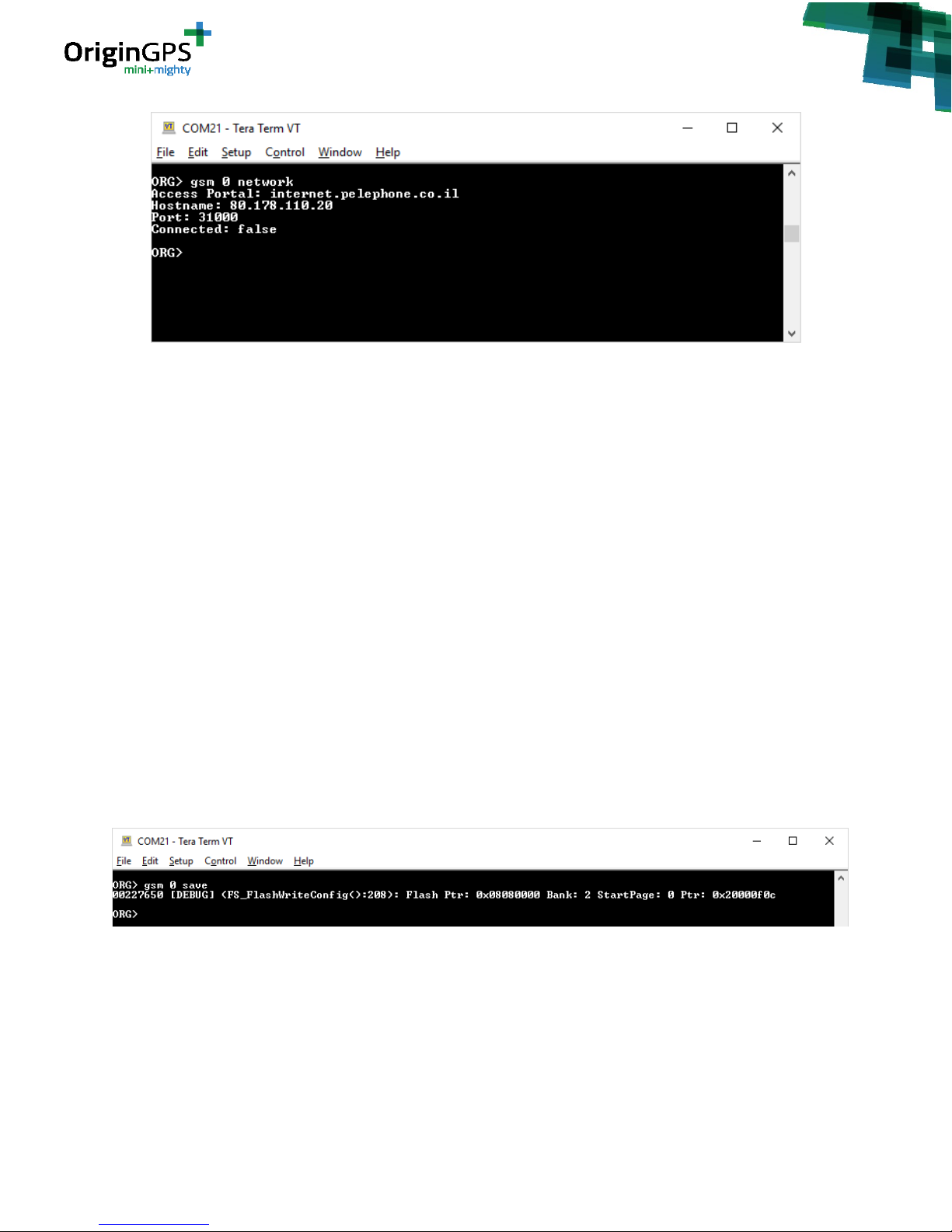
4. Once the changes are made, the operator must save them to flash using the command:
gsm 0 save
See figure 5 for example.
Figure 5 – Setting Origi nIoT network co nfiguration and saving to flash
10.3. ENTERING CELLULAR-NETWORK PARAMETERS – GSM/LTE AUTHENTICATION
COMMAND
In order to configure your SIM card, use in the debug console the “authen” command. To see current
configuration, input:
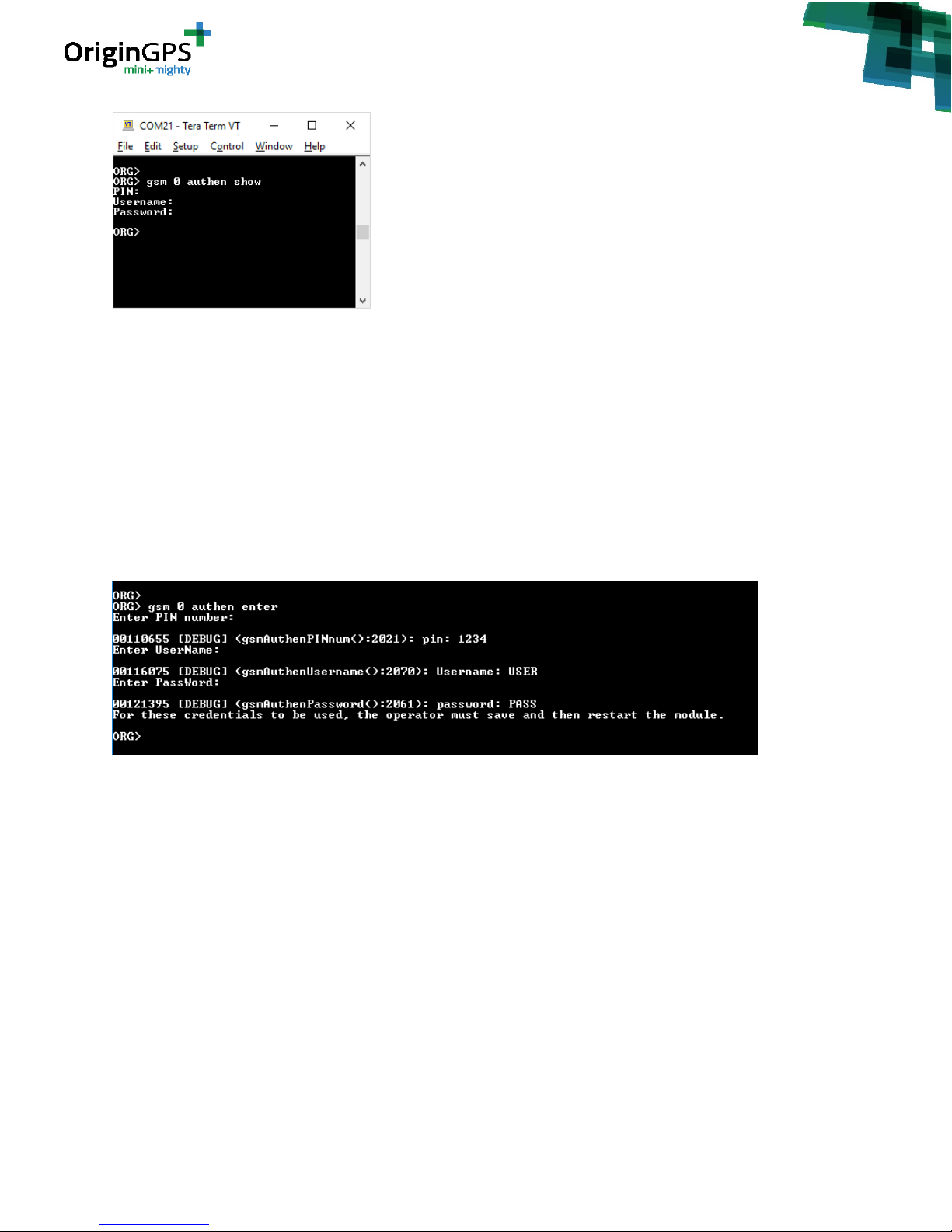
gsm 0 authen show
You will receive the following output:
Page 14
- 14 -
OriginIoT EVK User Guide Rev. 1.1 5.13.18
Since the module is shipped without authentication settings, they are shown as empty fields here. The
“authen” sub-command lets the operator set 3 fields: PIN, Username and Password. The PIN is a 4-8
digit number provided with the SIM card, if required by the operator. If Username and Password are
required (see section 9.3) then the values of these fields are provided by the network operator as well. If
there is no requirement for them then these fields can remain blank.
To set these fields use the command:
gsm 0 authen enter
The operator will be prompted for each of the 3 fields. If the field is not required, exit the field by typing
the “Enter” key.
Once completed, the operator can once again use the command “ gsm 0 authen show” to check that the
values entered are correct. If they values are correct, they must be saved to flash using the following
command:
gsm 0 authen save
The next time the system boots these fields will be used in the wireless network connectivity.
5. In the end of the process, while the EVK is successfully connected to a server, the output should look
like this:
ORG> gsm 0 network
Access Portal: internet.com
Hostname: 80.178.110.20
Port: 31000
Connected: true
Page 15

- 15 -
OriginIoT EVK User Guide Rev. 1.1 5.13.18
IP Address: 25.48.187.64 (the IP is dynamic)
The last entry “IP Address” is the GSM/LTE’s IP address given to the module by the Internet providers
DHCP servers and is not a configurable item.
11. ORIGINIOT WEB APPLICATION
11.1. OVERVIEW
This chapter applies to users who choose to use OriginIoT evaluation server. The OriginIoT™ web
application server is an interface to configure and view modules with associated interfaces, devices,
messages, and commands. User-created and System commands can be executed via user friendly GUI
interfaces.
11.2. USER LOG IN
Website address of the web application is: http://18.184.85.170 (resides on Amazon Web Services
cloud).
When entering this address, you will be automatically redirected to the login page. See figure 6.
Figure 6 – OriginIoT Web Application, login page
Please enter the credentials you received from your OriginGPS representative. You will be able to change
the password from the Profile tab. Clicking the ✓ symbol will redirect you to the Home tab.
11.3. WEB HOME TAB
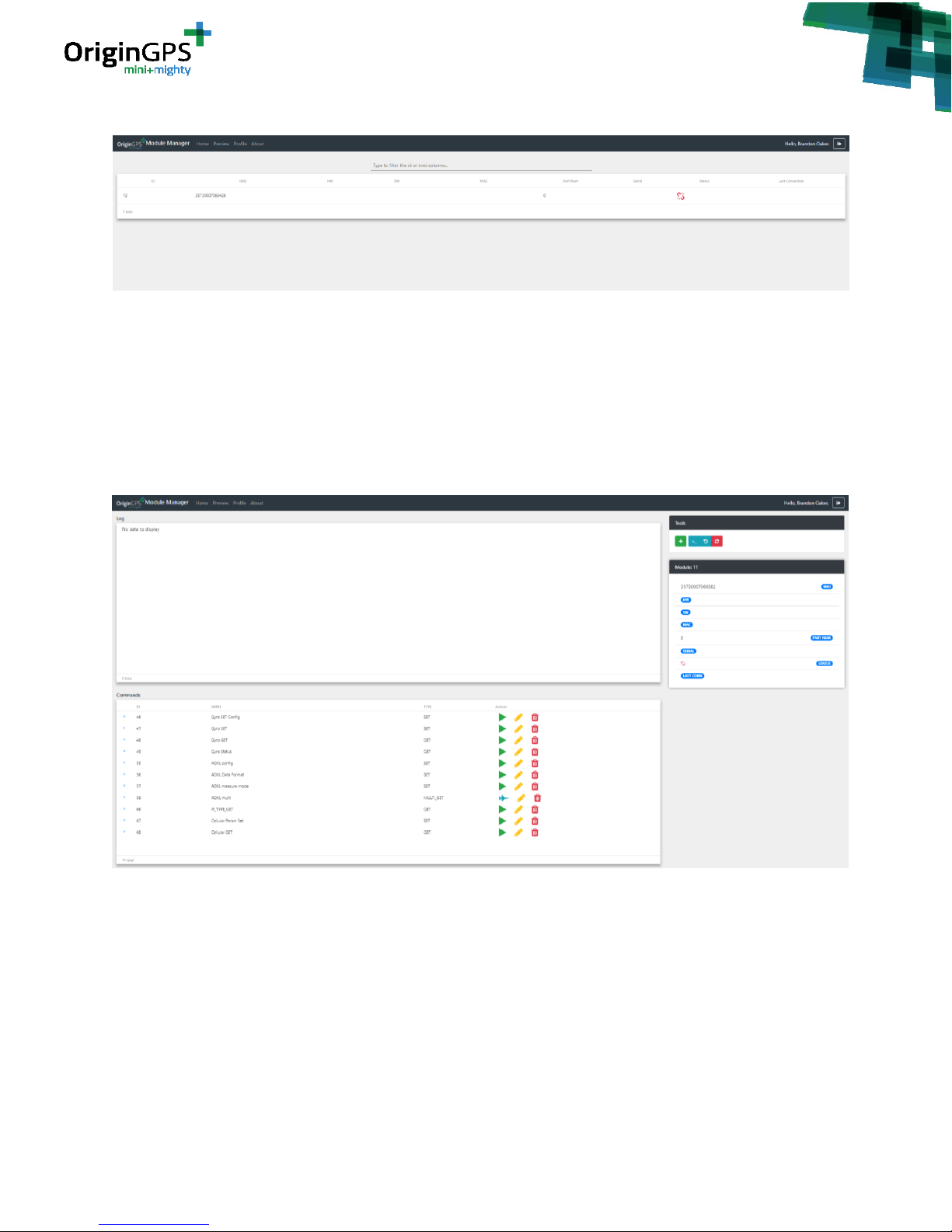
Each OriginIoT module has an ID number associated to it by this specific server. The unique ID in the
server is associated with the module upon its first registration to the server. The unique ID is linked to
the module’s IMEI (International Mobile Station Equipment Identity). The modules that you purchased
Page 16
- 16 -
OriginIoT EVK User Guide Rev. 1.1 5.13.18
are added by us to your profile and will appear once you are logged in.
Figure 7 – OriginIoT Home Tab
Clicking the row of the module will forward you to the device details page. Red link symbol in the status
column shows the connection status of your OriginIoT. Red symbol means no connection, green means
good connection between module and server. Note you will need to refresh the page to get the latest
connectivity status from the modules.
11.4 MODULE DETAILS TAB
Figure 8 – Module Details Tab
There are 4 windows in the module details tab: Log, Commands, Tools and Details.
• Log – showing data sent and received to/from the module. The log is saved locally, it will be
deleted if page is refreshed.
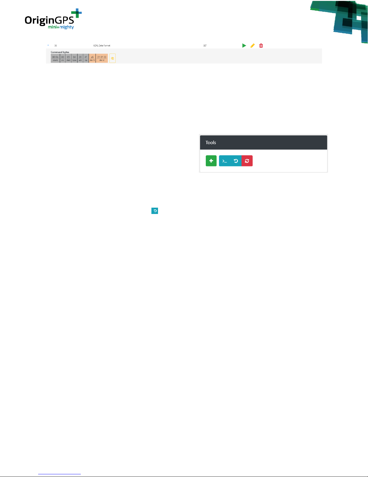
• Commands – showing all commands that were entered in the system. Clicking on the command
row will open up the command details line that shows the byte string that will be sent to the
module upon execution of the command (see figure 8). Clicking on the yellow copy button will
copy the command byte string to the clipboard as a string (00 0b 80 05 04…).
Page 17
- 17 -
OriginIoT EVK User Guide Rev. 1.1 5.13.18
Figure 8 – Command details
Each command has three buttons in its line: play, edit and delete. Play takes the form of a blue
airplane symbol when a mutli_GET or Multi_BUF command is entered. The green play symbol
executes the command, you will see the sent command in the log. The blue airplane button will
route the user to the preview tab, where he can see the data in the widgets. The yellow edit
button will open the new message windows pre-loaded with the data of the edited message.
The red delete button remove the command from the list and from the database.
• Tools – allows the user to choose from 3
available options (red reset button not
implemented yet).
• The green “+” button opens a new message
window and allows the user to add a new
command.
• The “>_” button allows the user to write a custom message, bypassing the new message
window restrictions.
• The blue “loopback” button initiates a loopback test to test the link status of the module
to the server. By executing a loopback test you can ping the module in order to check its
connectivity status (this test only checks the connectivity of the module to the server, not
the link state or status of peripheral sensors/devices). The structure of the loopback test
message is described in API specifications document. The created sent message and the
message received from the module will show up on the log area. If unsuccessful, you will not
receive any response.
Note: you will not receive a success notification if the module is not yet connected to the
server.
If you are connected to debug console, please wait until you receive:
00021788 [INFO] (MCU_ProcessAdminMsg:1086) Module is registered with
host application.
In the debug console, successful loopback message will print:
ORG> (MCU_ProcessSetMsg:1027): Received App Loopback message
0x000000: 00 0d 80 00 04 20 41 00 64 01 02 03 04 .....
A.d....
(MCU_ProcessSetMsg:1043): Outgoing message...
0x000000: 00 0c 00 80 10 20 00 65 01 02 03 04 .....
.e....
• Module Details – shows the IMEI and the link state of the module, with place holder for future
HW and SW versions, last connection time, MAC address and module serial number.
Page 18
- 18 -
OriginIoT EVK User Guide Rev. 1.1 5.13.18
11.5 ADDING A NEW COMMAND
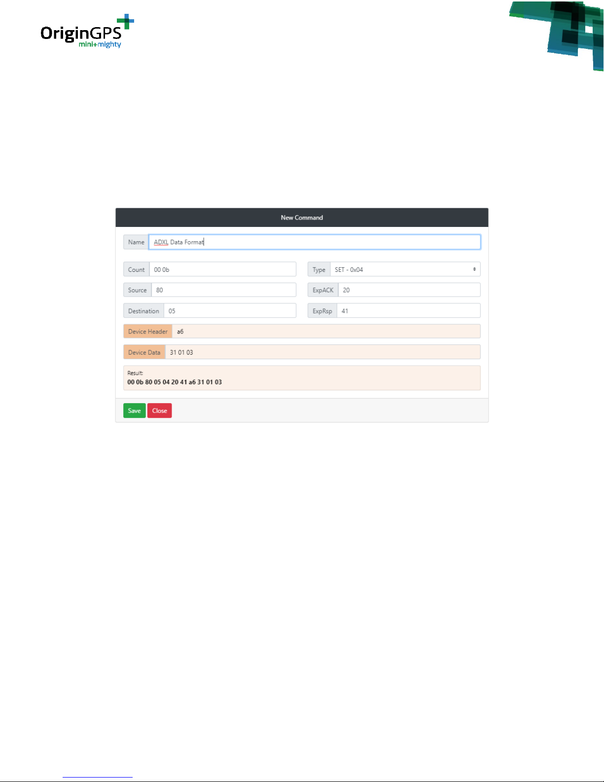
For the user convenience, the New Command window allows to easily define a message via online form.
There are no format constraints for the inputs so user has to make sure data is inserted correctly, two
characters for bytes (Hexadecimal) with space between bytes. The count field is updated automatically
when new bytes are added/removed.
Please consult the OriginSmart API Specification document to learn what inputs are required in Type,
Source, Destination, ExpAck, ExpRsp, Device Header and Device Data.
The result command is the actual string that will be sent to the module.
Figure 9 – New Command
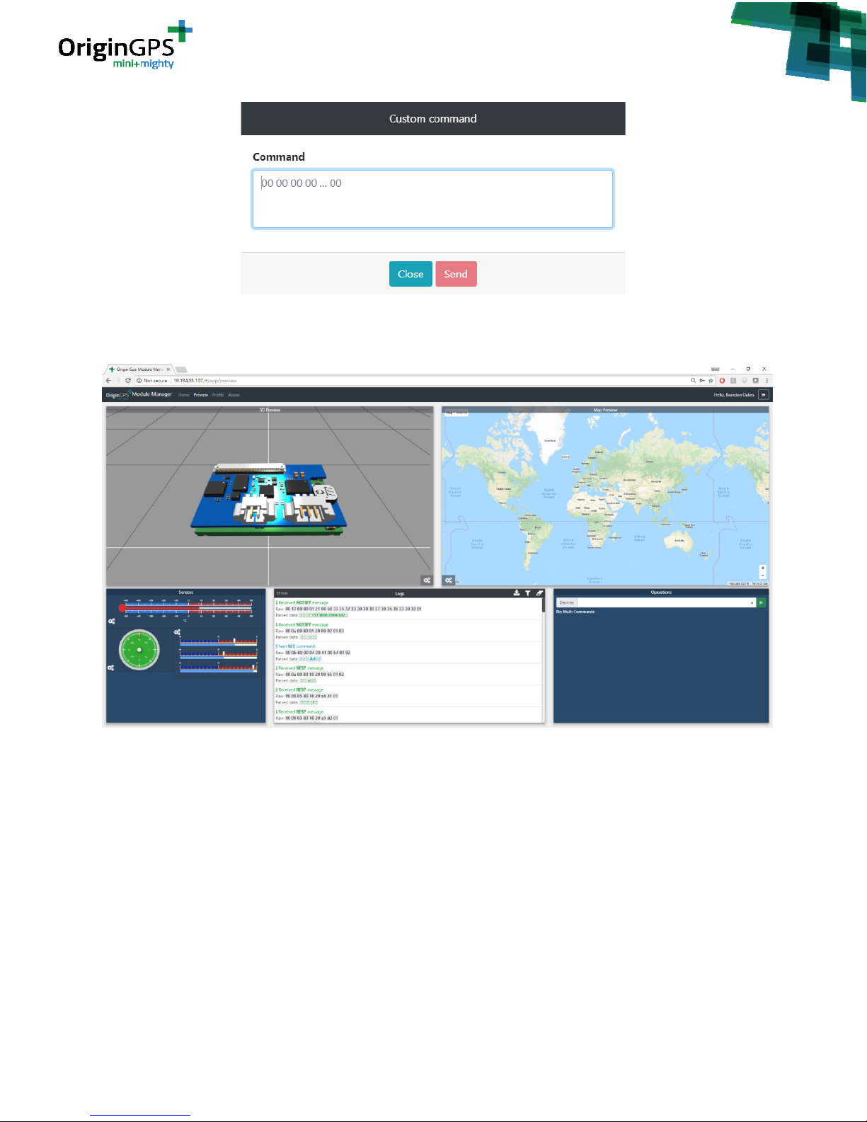
11.6 ADDING A CUSTOM COMMAND
The user can send any string he wants to the device using this custom command feature. If the
command cannot be interpreted by the OriginIoT module, no response will be issued. If the first two
bytes in the system, which are dedicated for message length, are not correct, the message will not be
sent to the module.
The user can reach the custom command window by clicking on the “>_” button in the Tools section.
Clicking on Close will close the window without sending. Clicking on Send will send the message and
close the window.
Page 19
- 19 -
OriginIoT EVK User Guide Rev. 1.1 5.13.18
Figure 9 – Command details
11.7 WIDGET PREVIEW TAB
Figure 10 – Widget preview tab
OriginGPS has developed some sample widgets to demonstrate the functionality of the module. These
widgets include:
• 3D Preview of the module+addon1 assembly, controllable by accelerometer
• Google maps preview, showing GNSS locations
• Sensors preview, showing temperature, compass, and gyro data.
• Logs, showing raw data transferred to and from the module. The log widget allows you to filter
some of the messages (GNSS, Registration, Loop Back, Multi_Get). The log widget also allows
you to download the data of the log as a .log file.
• Operations, allowing the user to select which device to operate according to IMEI; start/stop
listening to selected device, and start/stop Multi_Get and Multi_Buf messages.
Page 20
- 20 -
OriginIoT EVK User Guide Rev. 1.1 5.13.18
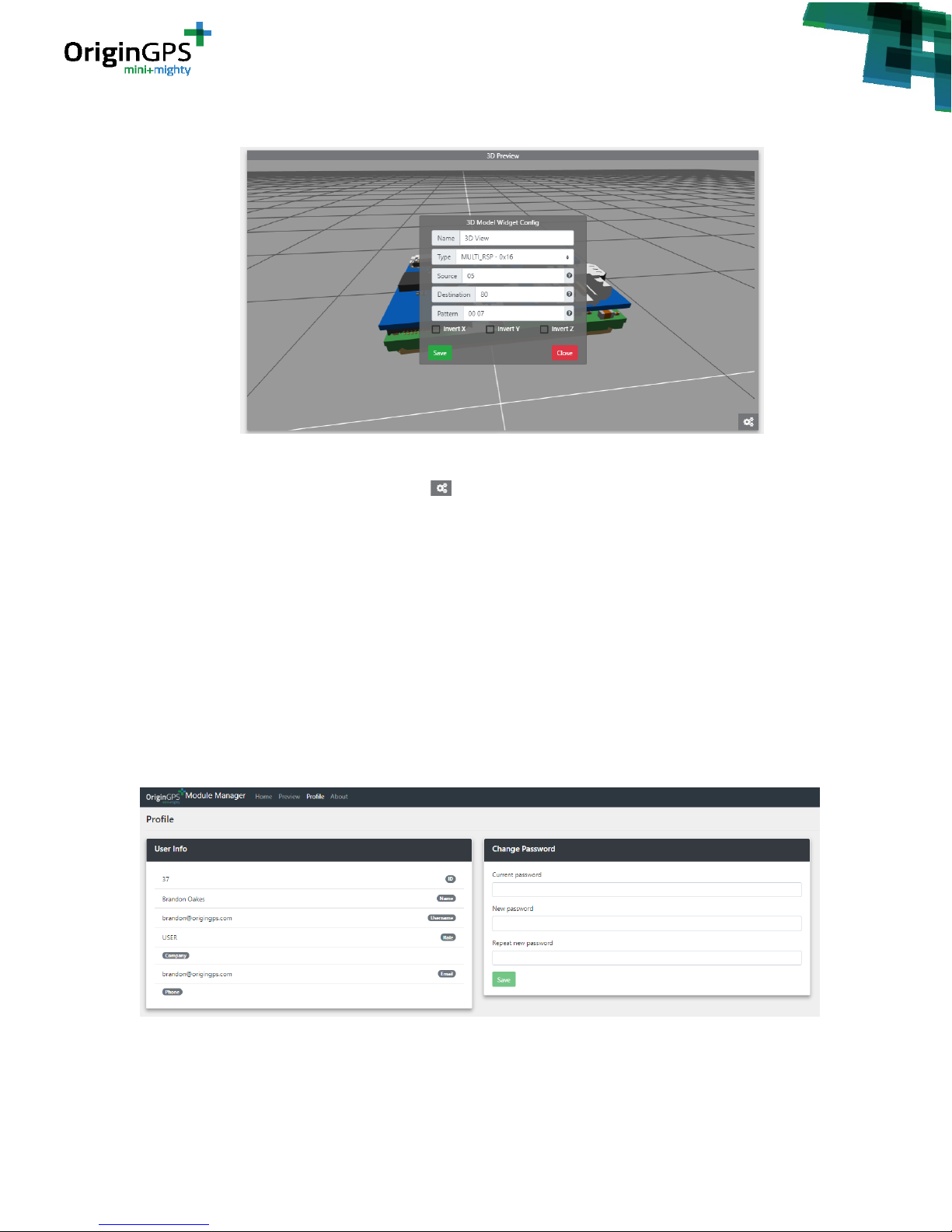
11.8 WIDGET CONGIFURATION
Figure 10 – Widget configuration window
Each widget can be configured by clicking the button in its corner. In order for the widget to present
the required information, the user needs to set the type of message to listen to. The fields name, type,
source, destination and pattern are common to all widgets. Widgets that are planed to be used with 3
dimensional data have invert axis function that adds a (-) sign to all raw data (in case your sensor is
physically oriented in negative direction).
In “name” you can put any string as input. “type” allows you to choose from a drop-down menu. Under
“source” and “destination” you should choose the hexadecimal interface ID from which and to where
your message is sent (the message you want to present with the widget).
“Pattern” allows you to choose which of the messages from the chosen interface to listen to. The
pattern should be in Hexadecimal byte sting (not a string). For example, if you look for a $GNRMC NMEA
message, you should enter 24 47 4e 52 4d 43.
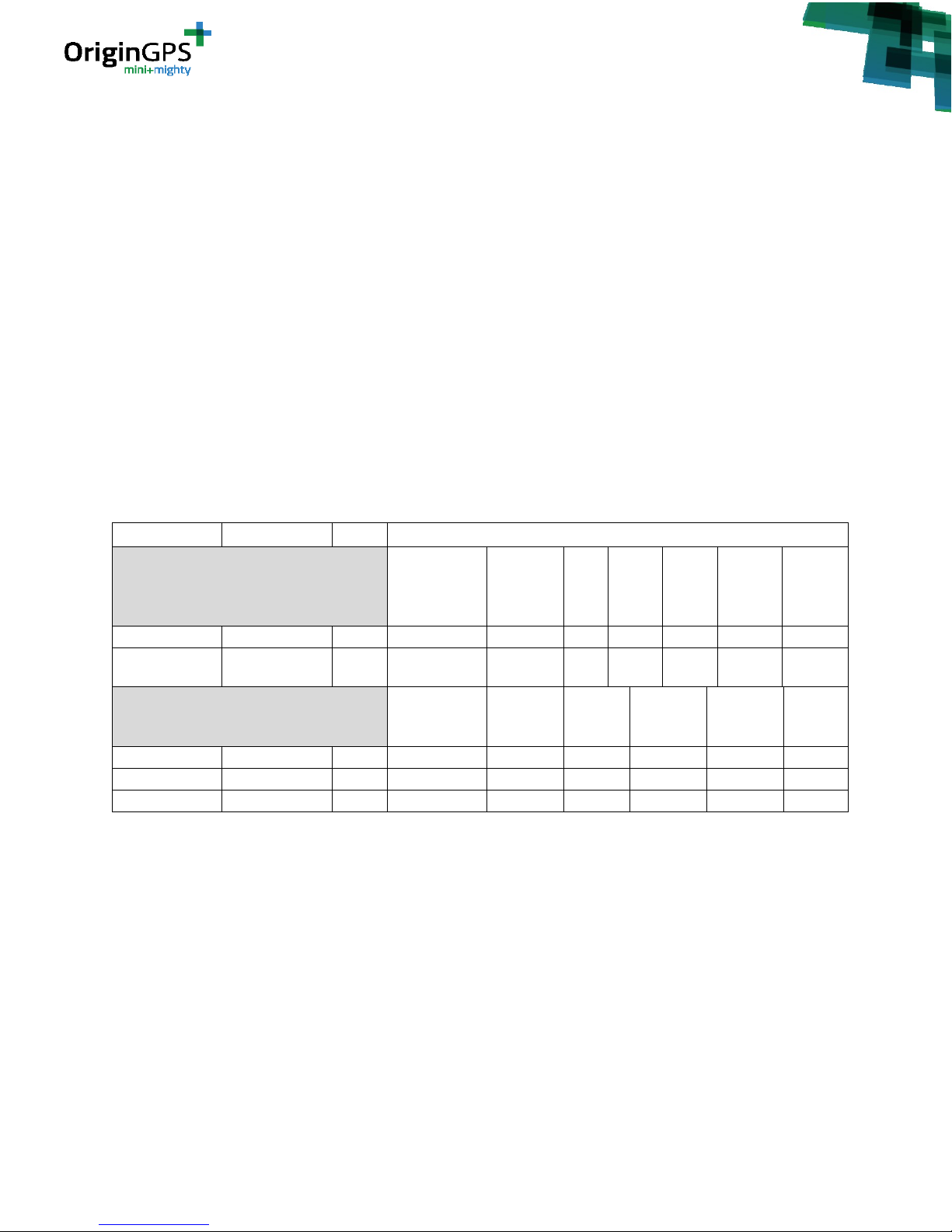
11.9 PROFILE TAB
Figure 11 – Profile Tab
The profile tab allows the user to see its info: ID, Name, Username, role (user or admin), company, email
and phone number. This tab also allows the user to change his password.
Page 21
- 21 -
OriginIoT EVK User Guide Rev. 1.1 5.13.18
12. OPERATING THE SENSORS ON THE EVK
The EVK has 5 sensors (including the GNSS sensor on the OriginIoT module) connected via 3 interfaces:
GNSS and temperature sensors connected via two UART interfaces (IF_20 and IF_03 respectively)
Accelerometer, Compass and Gyroscope connected via I2C (IF_05).
12.1 PARAMETER SETUP
All sensors must to be configured (“Committed”) on the device using an IF_PARAM_SET message has
specified in the API spec document.
The required parameters for each peripheral device can be found in the device datasheet. OriginIoT
module does not restrict the developer with the specific devices that he can connect to the module as
long as they interface with I2C, UART, SPI or GPIO. Every device has its own parameters that are
required in this step. For convenience, table 3 below lists all the parameters that are required for
configuring the devices that the EVK equips.
Device
Device P/N
IF_ID
Parameters
UART Type Interface
Baud Rate
Flow
Control
Stop
Bit
Parity
Data
Bits
Data
Ready
IF_ID
Data
Over
Run
Action
GPS
ORG4572
03
4800-230400
Disable
1
None 8 N/A
N/A
Temperature
TMP104
20
Auto-baud
mode 3
Disable
1
None 7 N/A
N/A
I2C Type Interface
Addressing
Mode
Bit Rate
Register
Type
Data
Ready
IF_ID
Data Over
Run
Action
Device
Address
(0x)
eCompass
IST8304
05
7-bit
100 kbps
BYTE
N/A
N/A
18
Gyroscope
DM00168691
05
7-bit
100 kbps
BYTE
N/A
N/A
d2
Accelerometer
ADXL345
05
7-bit
100 kbps
BYTE
N/A
N/A
a6
Table 3 – Configuration parameters for EVK sensors
If you are using a debug console, you will see this message printed after successful configuration
message (in this example we commit the accelerometer ADXL345):
(MCU_ProcessParamSetMsg:575): Parameter Set Dump...
0x000000: 00 13 80 00 04 20 41 00 06 05 03 00 01 01 53 00 .....
A.......S.
0x000010: 00 00 00 ...
(I2C_ProcessParamSetMessage:360): PARAM_SET command...
0x000000: 00 13 80 00 04 20 41 00 06 05 03 00 01 01 53 00 .....
A.......S.
0x000010: 00 00 00 ...
(I2C_ProcessParamSetMessage:413): Outgoing I2C Response message...
0x000000: 00 0b 00 80 10 20 00 07 05 03 01 ..... .....
Page 22
- 22 -
OriginIoT EVK User Guide Rev. 1.1 5.13.18
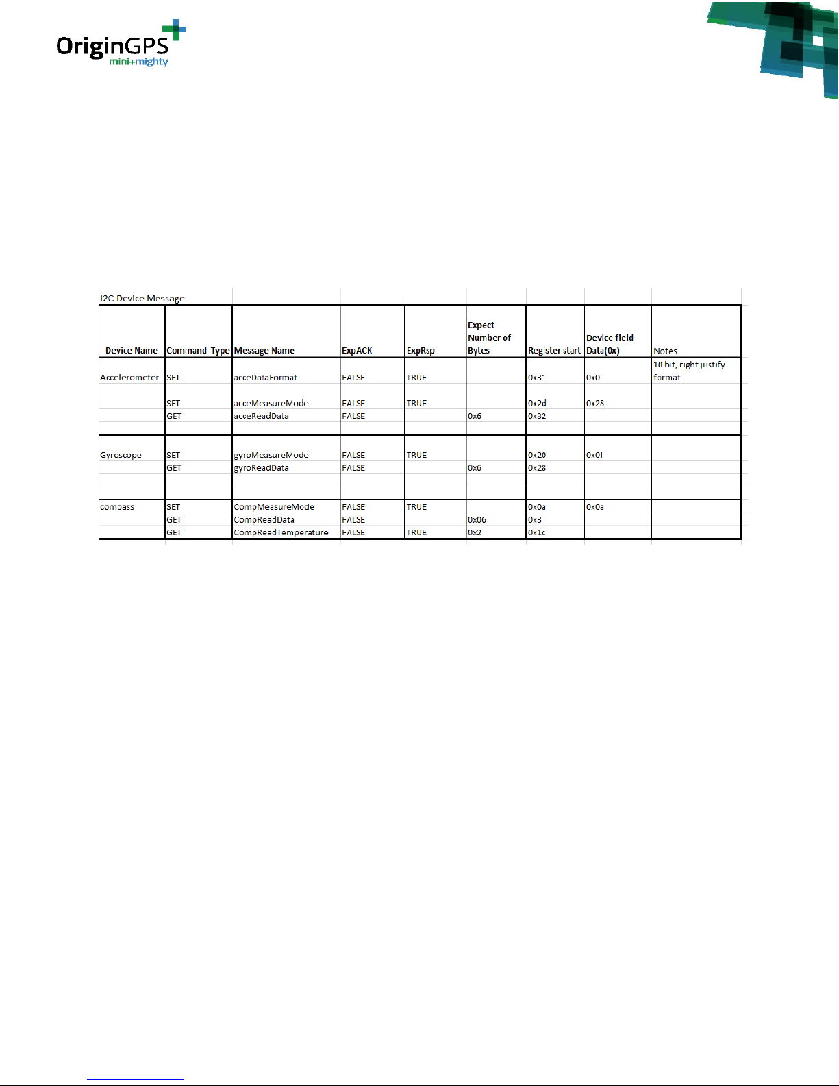
12.2 ACTIVATING THE SENSORS
To understand what messages shall be sent to achieve a certain functionality for a specific device one can
refer to the datasheets of the devices. Usually under “Register map” you will find the description of the
functionality each register address is responsible for and what kind of data to set in it to achieve this
functionality. This will help you fill the register start, device field data and expected number of bytes fields
in SET and GET messages (please refer to API spec document to see the complete message structure). The
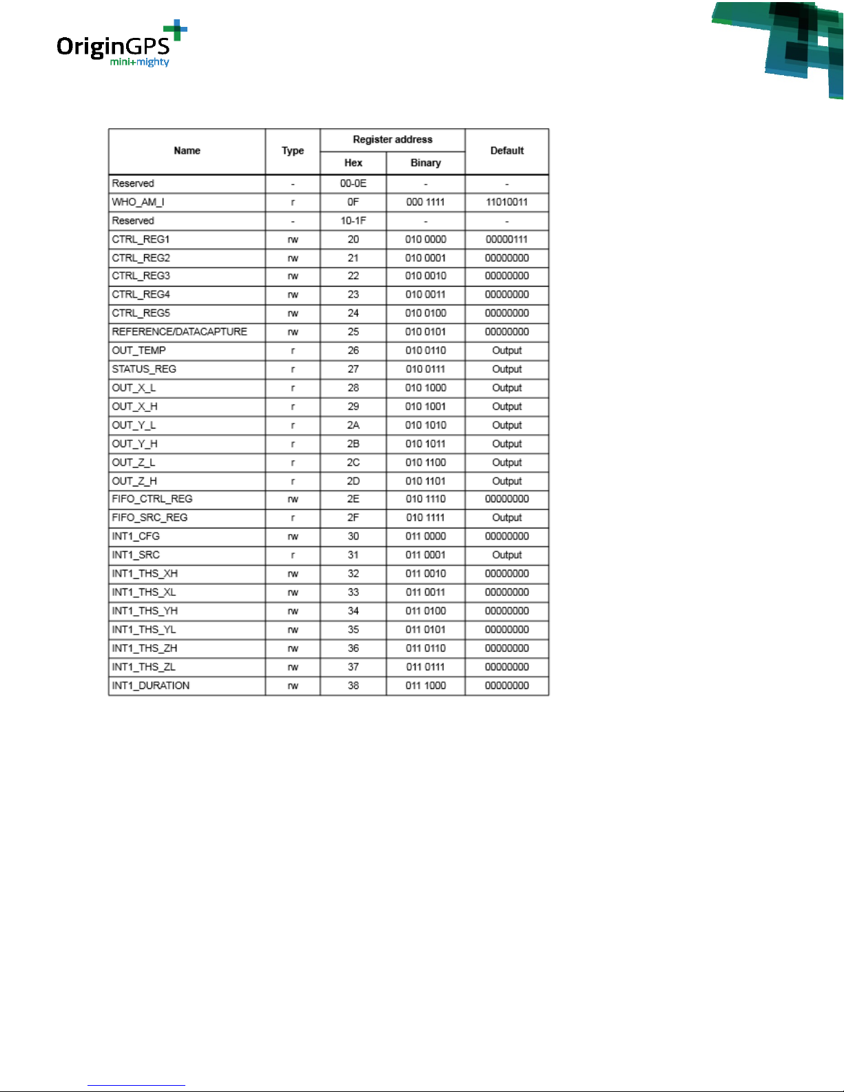
full register map of the devices on the EVK can be found in appendix C.
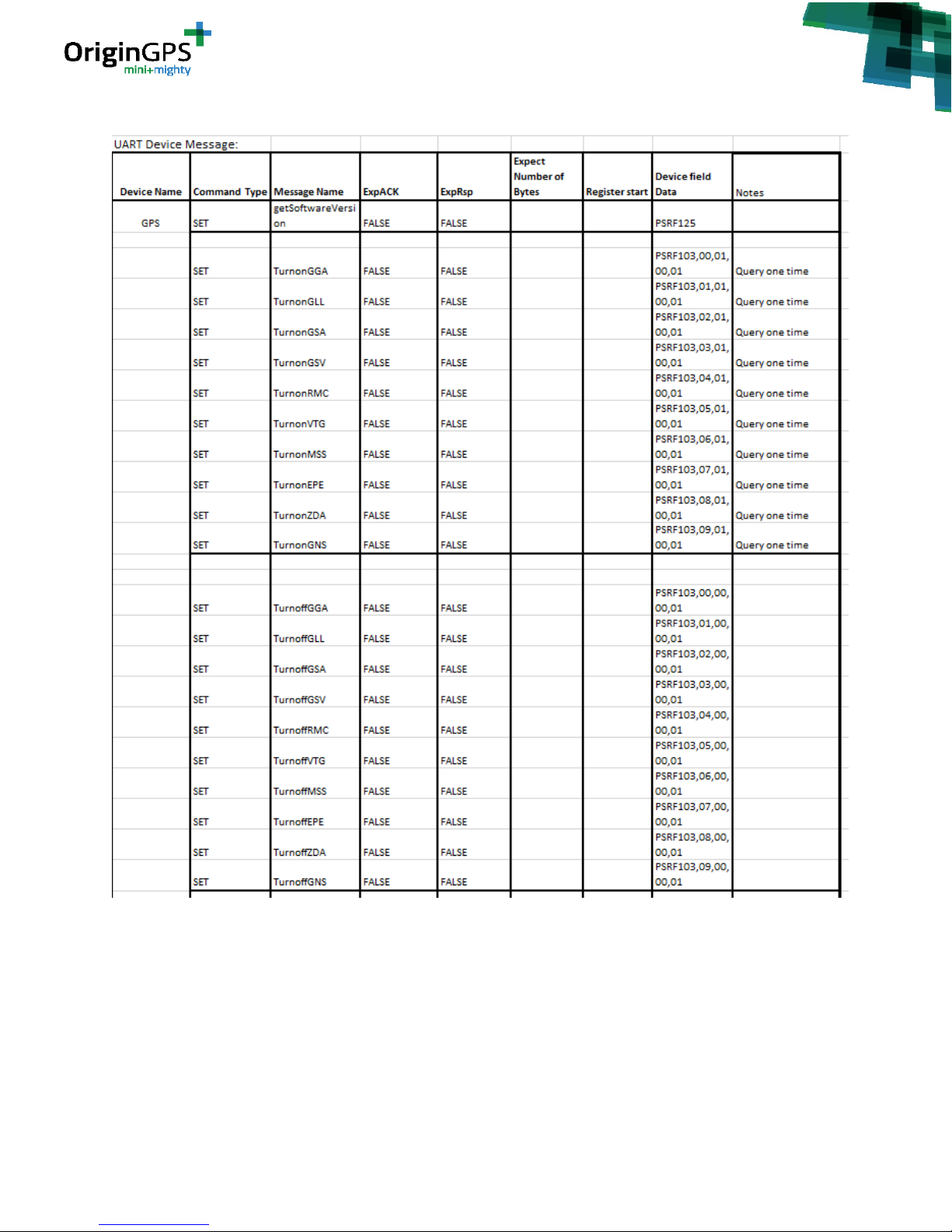
For your convenience, tables 4 and 5 offer sample set and get message configurations for the sensors.
Table 4 – Configuration for I2C Messages
Page 23
- 23 -
OriginIoT EVK User Guide Rev. 1.1 5.13.18
Table 5 – Configuration for UART Messages
If you are using a serial debug console you will be able to see the commands received on the module
and the responses issued by the module. For example, this is what you will receive on the console after
successful dataFormat SET message, measureMode SET message and readData GET messages for the
accelerometer:
(i2cProcessSetMsg:759): Set message...
0x000000: 00 0b 80 05 04 20 41 53 31 01 00 ..... AS1..
Page 24

- 24 -
OriginIoT EVK User Guide Rev. 1.1 5.13.18
00260504 [DEBUG] (i2cProcessSetMsg():764): the Ack flag: 0x20 the RSP
Flag: 0x41
00260505 [DEBUG] (i2cProcessSetMsg():769): Device Address: 0x53
00260520 [DEBUG] (i2cProcessSetMsg():784): The Start Reg: 0x31
00260532 [DEBUG] (i2cProcessSetMsg():797): Number of bytes: 1
(i2cProcessSetMsg:834): Outgoing Set msg Response...
0x000000: 00 09 05 80 10 20 53 31 01 ..... S1.
(i2cProcessSetMsg:759): Set message...
0x000000: 00 0b 80 05 04 20 41 53 2d 01 28 ..... AS-.(
00275941 [DEBUG] (i2cProcessSetMsg():764): the Ack flag: 0x20 the RSP
Flag: 0x41
00275942 [DEBUG] (i2cProcessSetMsg():769): Device Address: 0x53
00275957 [DEBUG] (i2cProcessSetMsg():784): The Start Reg: 0x2d
00275969 [DEBUG] (i2cProcessSetMsg():797): Number of bytes: 1
(i2cProcessSetMsg:834): Outgoing Set msg Response...
0x000000: 00 09 05 80 10 20 53 2d 01 ..... S-.
(i2cProcessGetMsg:443): Get Message...
0x000000: 00 09 80 05 02 20 06 53 32 ..... .S2
(i2cProcessGetMsg:503): Outgoing Get response msg...
0x000000: 00 0f 05 80 10 20 53 32 06 0a 00 07 00 e7 00 .....
S2.......
12.2 WIDGET CONFIGURATION
For your convenience we added table 5 below to help in configuring the widgets to listen to the sample
sensors messages.
Widget
Sensor
Type
Source
Destination
Pattern
3D Preview
ADXL345
MULTI_RSP – 0x16
05
80
00 06
Map Preview
GNSS (Internal)
NOTIFY – 0x01
03
80
24 47 4e 52 4d 43
Temperature
IST8304
MULTI_RSP – 0x16
05
80
00 02
Compass
IST8304
MULTI_RSP – 0x16
05
80
00 06
Gyro
DM00168691
MULTI_RSP – 0x16
05
80
00 06
Page 25
- 25 -
OriginIoT EVK User Guide Rev. 1.1 5.13.18
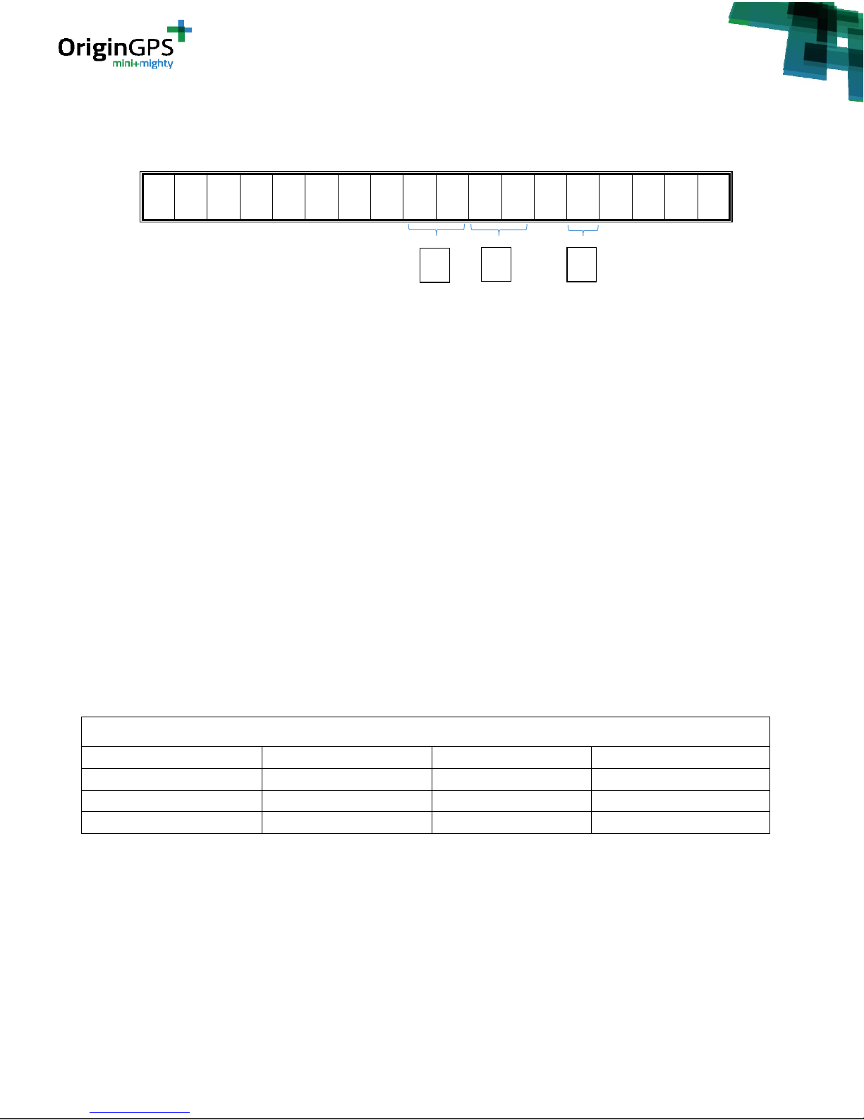
13. ORDERING INFORMATION
1. Selection of communication technology:
2G = 2G GPRS
3G = 3G HSPA
C1 = LTE Cat 1
CM = LTE Cat M*
NB = LTE Cat NB1 *
2. Selection of communication:
EU= EMEA/APAC
GL=Global
US = North America
JA = Japan
CH = China
3. Selection of SIM type
T = Traditional plastic SIM card holder
E = Embedded SIM
* Please contact [email protected]
List of orderable parts
ORG2101-2GEU-T-EVK
ORG2101-3GEU-T-EVK
ORG2101-C1US-T-EVK
ORG2101-2GEU-E-EVK
ORG2101-3GEU-E-EVK
ORG2101-C1US-E-EVK
ORG2101-2GGL-T-EVK
ORG2101-3GUS-T-EVK
ORG2101-C1JA-T-EVK
ORG2101-2GGL-E-EVK
ORG2101-3GUS-E-EVK
ORG2101-C1JA-E-EVK
Table 7: list of o rderable parts
Please refer to document “ORG2101 Datasheet” for complete details of the devices.
APPENDIX A – PORTS AND POWER
Power input connector – J26. 6V/3A. or J22 USB. To determine which is the power supply to be used use
jumper J24.
J22 is also used for serial debug console interface
O R G 2 1 0 1 - X X X X - X - E V
K
1
2
3
Page 26

- 26 -
OriginIoT EVK User Guide Rev. 1.1 5.13.18
USB 2.0 for input from external devices – J25.
MCU cold restart button – SW1
[Note: push the restart button for at list one second to allow GNSS module to fully restart]
Disconnect EVK sensors – Jumper J28
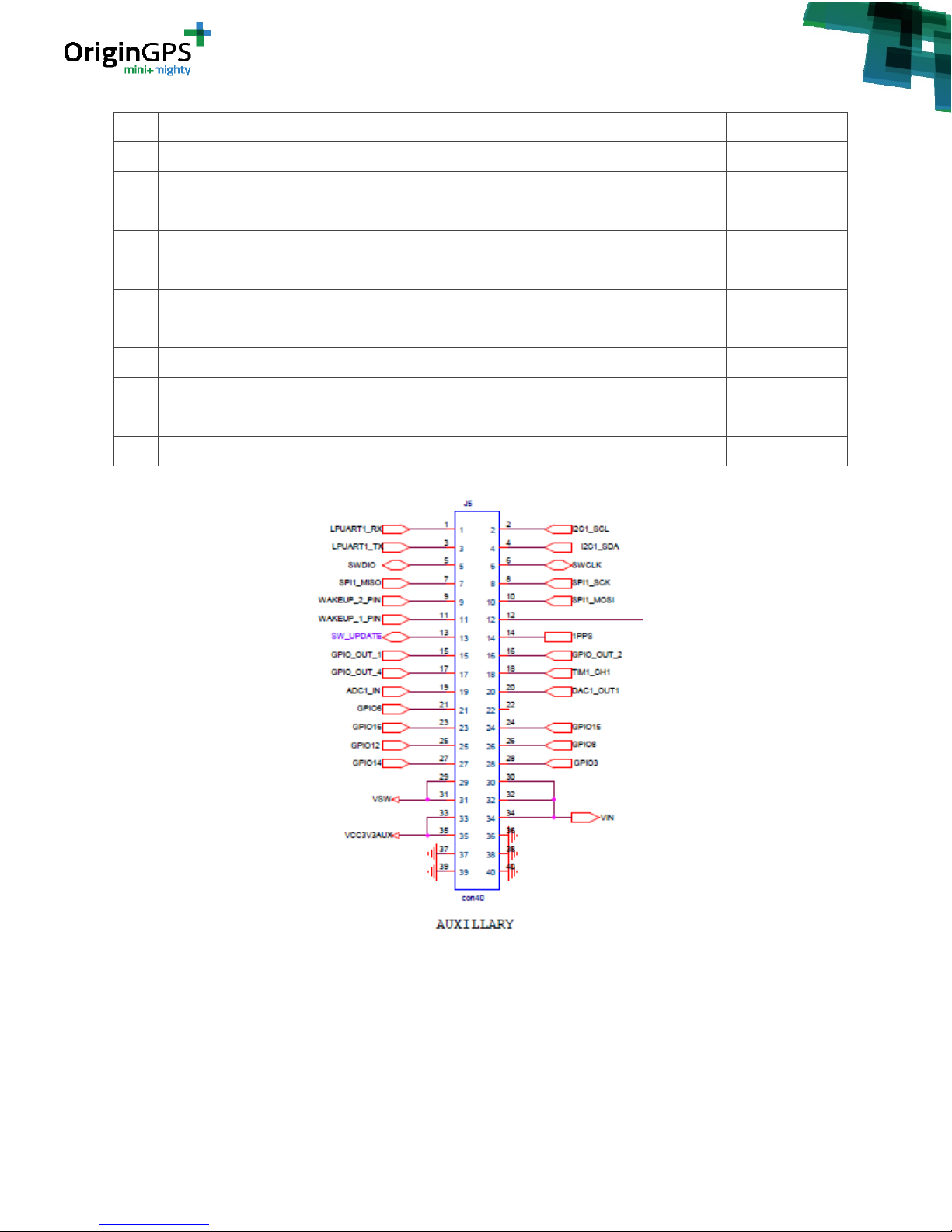
Auxiliary mezzanine connector - J5:
PAD
NAME
FUNCTION
DIRECTION
1
LPUART1_RX
UART Receive
Input
2
I2C1 SCL
I2C Serial Clock
Input
3
LPUART1_TX
UART Transmit
Output
4
I2C1 SDA
I2C Serial Data
Bi-directional
5
SWDIO
JTAG / Firmware Loading Pin
Bi-directional
6
SWCLK
JTAG / Firmware Loading Pin
Bi-directional
7
SPI1_MISO
SPI Data Out
Output
8
SPI1_SCK
SPI Serial Clock
Input
9
WAKEUP_2_PIN
Power Status
Output
10
SPI1_MOSI
SPI Data In
Input
11
WAKEUP_1_PIN
Power Status
Output
12
RST_MCU
Asynchronous Reset
Input
13
SW_UPDATE
Shutdown comm. module after SW update
Input
14
1PPS
UTC Time Mark
Output
15
GPIO_OUT_1
GPIO Output
Output
16
GPIO_OUT_2
GPIO Output
Output
17
GPIO_OUT_4
GPIO Out
Output
18
TIM1_CH1
Timer Function
Input
19
ADC1_IN
Analogue to Digital Input
Input
20
DAC1_OUT1
Digital to Analogue
Output
21
GPIO6
GPIO
Bi-directional
22
NC
Not Connected
23
Do not use
Not Connected
24
Do not use
Not Connected
25
GPIO12
GPIO
Bi-directional
26
GPIO8
GPIO
Bi-directional
27
GPIO14
GPIO
Bi-directional
28
GPIO3
GPIO
Bi-directional
Page 27
- 27 -
OriginIoT EVK User Guide Rev. 1.1 5.13.18
Figure 32 –J5 c onnector
29
VSW
Battery Power Input
Power
30
VIN
EVK Power Supply
Power
31
VSW
Battery Power Input
Power
32
VIN
EVK Power Supply
Power
33
VCC3V3AUX
3.3V Power Supply
Power
34
VIN
EVK Power Supply
Power
35
VCC3V3AUX
3.3V Power Supply
Power
36
GND
System Ground
Power
37
GND
System Ground
Power
38
GND
System Ground
Power
39
GND
System Ground
Power
40
GND
System Ground
Power
Page 28
- 28 -
OriginIoT EVK User Guide Rev. 1.1 5.13.18
APPENDIX B – FIRMWARE UPLOAD (FLASHING) FOR ORIGINIOT
MODULE
OriginIoT module in the EVK is supplied with the company proprietary OriginSmart™ FW, designed to
allow codeless configuration of the remote module without any FW changes.
If for any reason there is a need to upload firmware, this section explains how this is done.
Required equipment for FW upload:
- ST-Link/v2 ISOL STM8 & STM32 controller
- ST-LINK/V2 ISOL MCU STM8 & STM32 and STM32-ST-LINK Utility. This application can be downloaded
here:
http://en.freedownloadmanager.org/Windows-PC/STM32-ST-Link-Utility-FREE.html
1. The plug supplied along with ST-LINK/V2 controller is suggested for FW upload. Connect the plug to
the controller in orientation as shown in figure 33.
Figure 33: ST-Link plug orientation
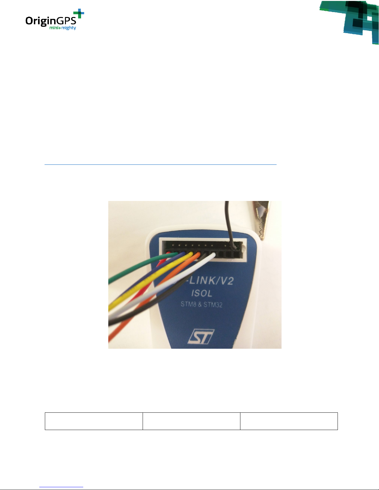
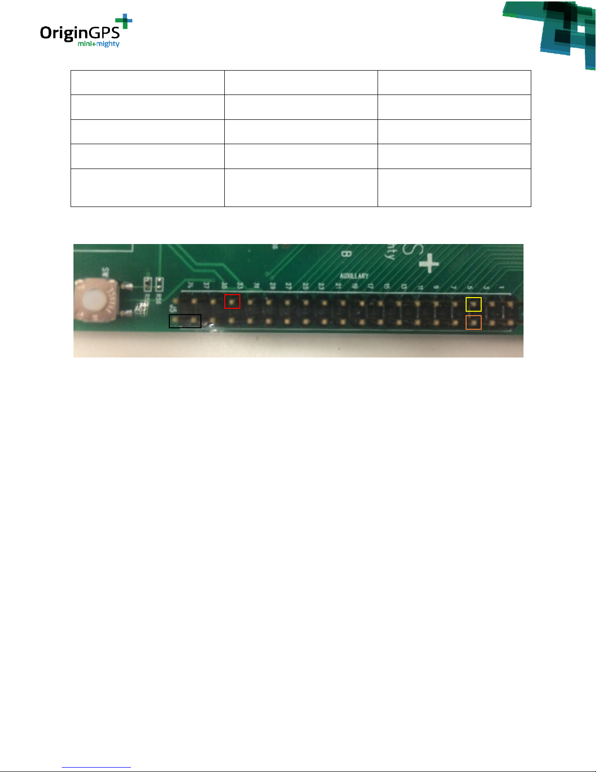
2. Connect the wires to the J5 connector on EVK board in a method that described in table 8 and
figures 34.
Wire Color
Function
Pin Number on J7 connector
Page 29
- 29 -
OriginIoT EVK User Guide Rev. 1.1 5.13.18
Black
Ground
38
Red
Vcc
33
Orange
JTAG / Firmware Loading Plug
6
Yellow
JTAG / Firmware Loading Plug
5
Black – Separate wire on top right
pin of controller
Ground
40
Table 8 – Wires Connection to EVK board
Figure 34: Wire Colors on J7 connector pins
All the other wires in the plug (green, blue, white) are not relevant and should not be connected.
3. Connect the ST-Link to PC via USB.
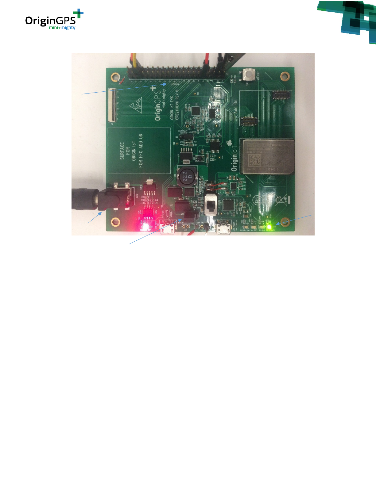
Power on the EVK and the module – plug power connector J26 or USB connector J22, place jumper
J24 accordingly.
Page 30
- 30 -
OriginIoT EVK User Guide Rev. 1.1 5.13.18
Figure 35: Power set up for FW upload
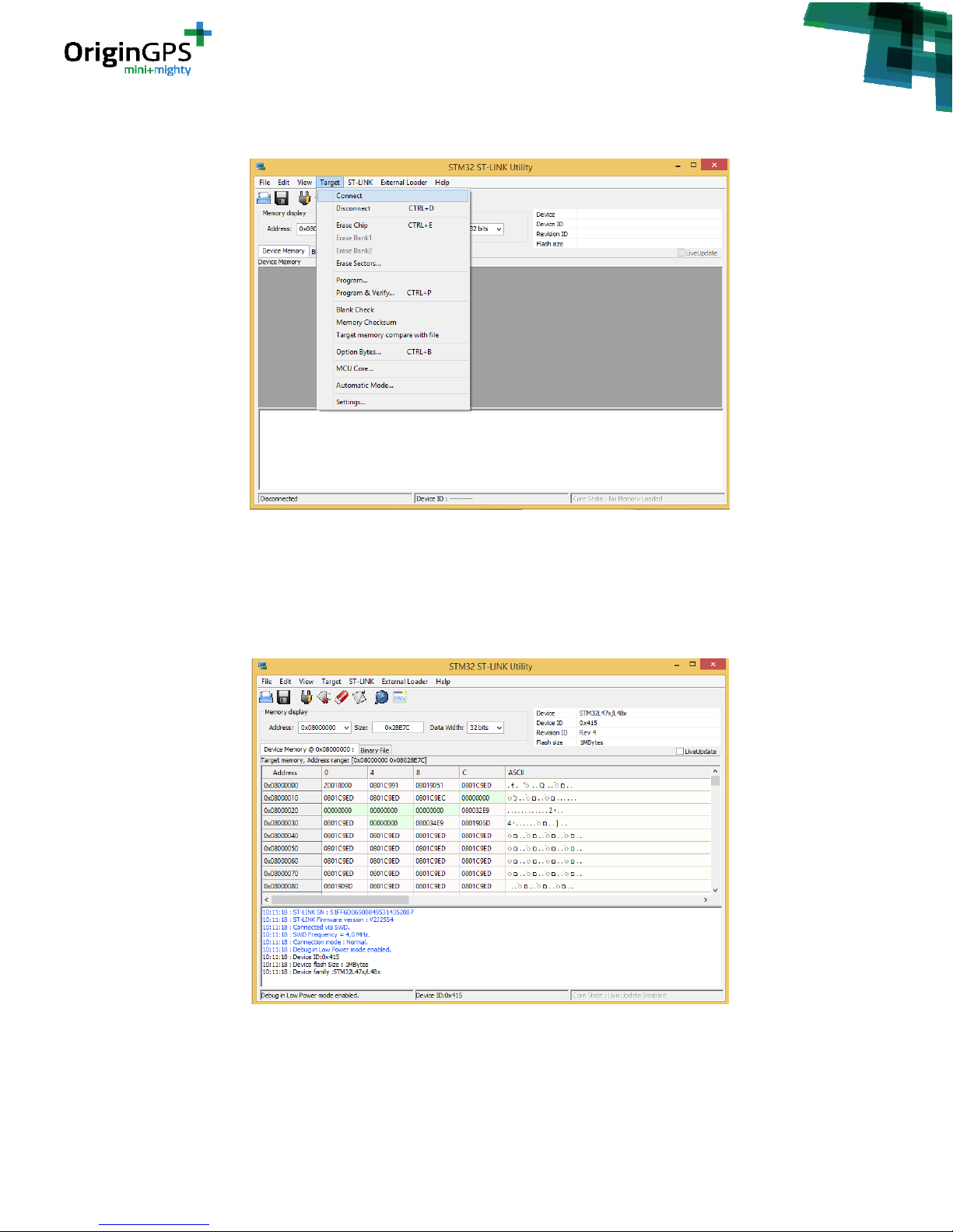
4. Open STM32 ST-LINK Utility.
Press Target -> Connect.
Connection of STLink to Auxiliary
connector J5
J26 EVK power
J24 Jumper choosing J26 as
power supply to Origin IoT
module
Led Indicating
power OK to
OriginIoT
module
Page 31
- 31 -
OriginIoT EVK User Guide Rev. 1.1 5.13.18
Figure 36: STM32 ST-Link Utility
5. In case the connection is fine, you should see the following screen, with message: ”Connected via
SWD”. See figure 37.
In case you get an error and cannot connect – please check your wires connection.
Figure 37: Connecting to module in STM32 ST-Link Utility
Page 32
- 32 -
OriginIoT EVK User Guide Rev. 1.1 5.13.18
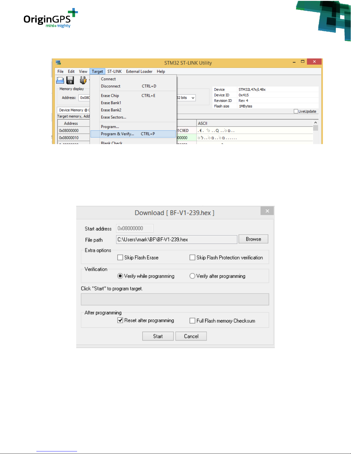
6. Click on “Target->Program & Verify”. See figure 38.
Figure 38: Program & Verify in STM32 ST-Link Utility
Open file dialog will open. Select your firmware file. This should be a .hex /.bin file.
7. After selecting the file, you will see “download” window. See figure 39. Press Start.
Figure 39: Download window
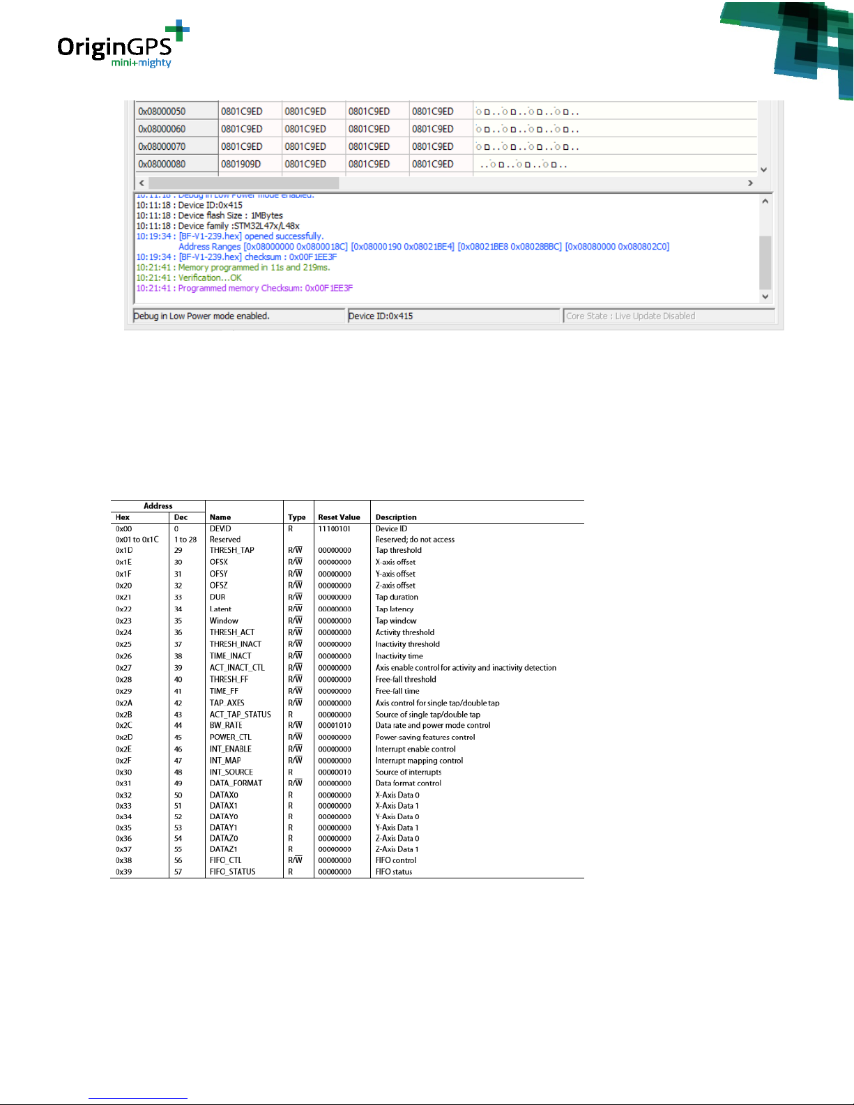
8. After finishing the firmware upload, you should see “Verification…OK” message. See figure 40.
Page 33
- 33 -
OriginIoT EVK User Guide Rev. 1.1 5.13.18
Figure 40: Successful Firmware Downloa d
9. Press “Target-> Disconnect” to disconnect the module.
APPENDIX C –REGISTER MAPS FOR SENSORS
Accelerometer -
TABLE 9– Accelerometer Register Map
Page 34

- 34 -
OriginIoT EVK User Guide Rev. 1.1 5.13.18
eCompass -
TABLE 10– eCompass Register Map
Page 35
- 35 -
OriginIoT EVK User Guide Rev. 1.1 5.13.18
Gyroscope
TABLE 11– Gyroscope Register Map
APPENDIX D – WORK WITH ORG2101 ADD-ONS
ORG2101 EVK allows developers to test their add-ons (or add-ons purchased directly from OriginGPS) in
two manners:
1. Dedicated connectors on EVK - J3 and J4
2. Flat Flexible Cable (FFC) connector – J6
To use this EVK functionality, additional required equipment is:
Page 36
- 36 -
OriginIoT EVK User Guide Rev. 1.1 5.13.18
1. Add-on developed according to guidelines in ORG2101 Datasheet document, or purchased
directly from OriginGPS (For FCC option it shall have FFC connector compatible with Molex
150150451)
2. Flat Cable connector Molex 150150451 or compatible (only for FFC connection option)
3. Battery compatible with the add-on used (only for FFC connection option)
In this appendix we will demonstrate using ORG2101-AD01 developed by OriginGPS as implementation
example.
D.1 Using Add-on via connectors J3 and J4
In this mode of operation, one can test the functionality of the add-on together with ORG2101 module
without connecting the add-on to external battery. The addon is powered by the power supply circuits
in the EVK.
Note: In this mode you will be able to use both the sensors on the EVK and the also the sensors on the
add-on. Make sure that sensors are not occupying the same I2C address as the sensors on the EVK (see
table 3)
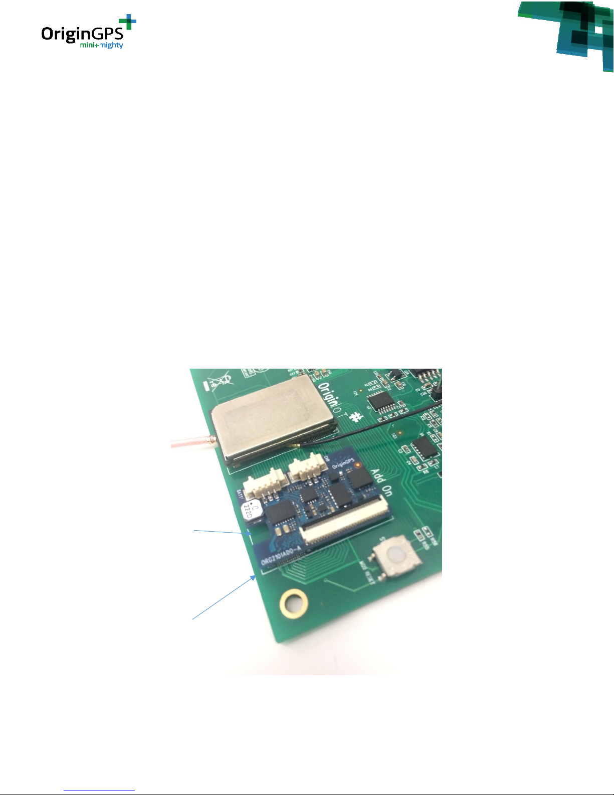
Please notice: connection of the add-on to EVK is unidirectional – J1 of the add-on (closer to GSM/LTE
antenna socket) should connect to J3 on the EVK.
You know that you are connected correctly if add-on fits in white outlines drawn on the EVK (silk screen)
Figure 41 – mati ng Add-on to EVK correctly
GSM Antenna
Socket
Add-on outline
drawn on the
EVK
Page 37
- 37 -
OriginIoT EVK User Guide Rev. 1.1 5.13.18
D.2 Using Add-on via FFC connector J6
Using add-on via FFC connector is the closest simulation for the real-life functionality of the add-on in a
product. In this mode the addon and the ORG2101 module are powered by a battery (and not from the
EVK). The FFC cable allows debugging via the serial console as described in section 9.2.
To use this mode your add-on should include FFC connector which is compatible with Molex FFC
150150451. Note: the flat cable is not included in the EVK.
The user can choose if he wants to operate the sensors on the EVK using Jumper J28. Disconnecting the
Jumper cuts power supply to the sensors on the EVK and allowing the user to work solely with the
sensors on the Add-on.
To connect Add-on and ORG2101 module through connector J6:
1. Prepare ORG2101 - Insert nano SIM card to its slot, Connect GSM/LTE antenna to the U.Fl
connector OriginIoT, Connect GNSS antenna to the W.Fl connector on OriginIoT, See figure 1
(section 9.2).
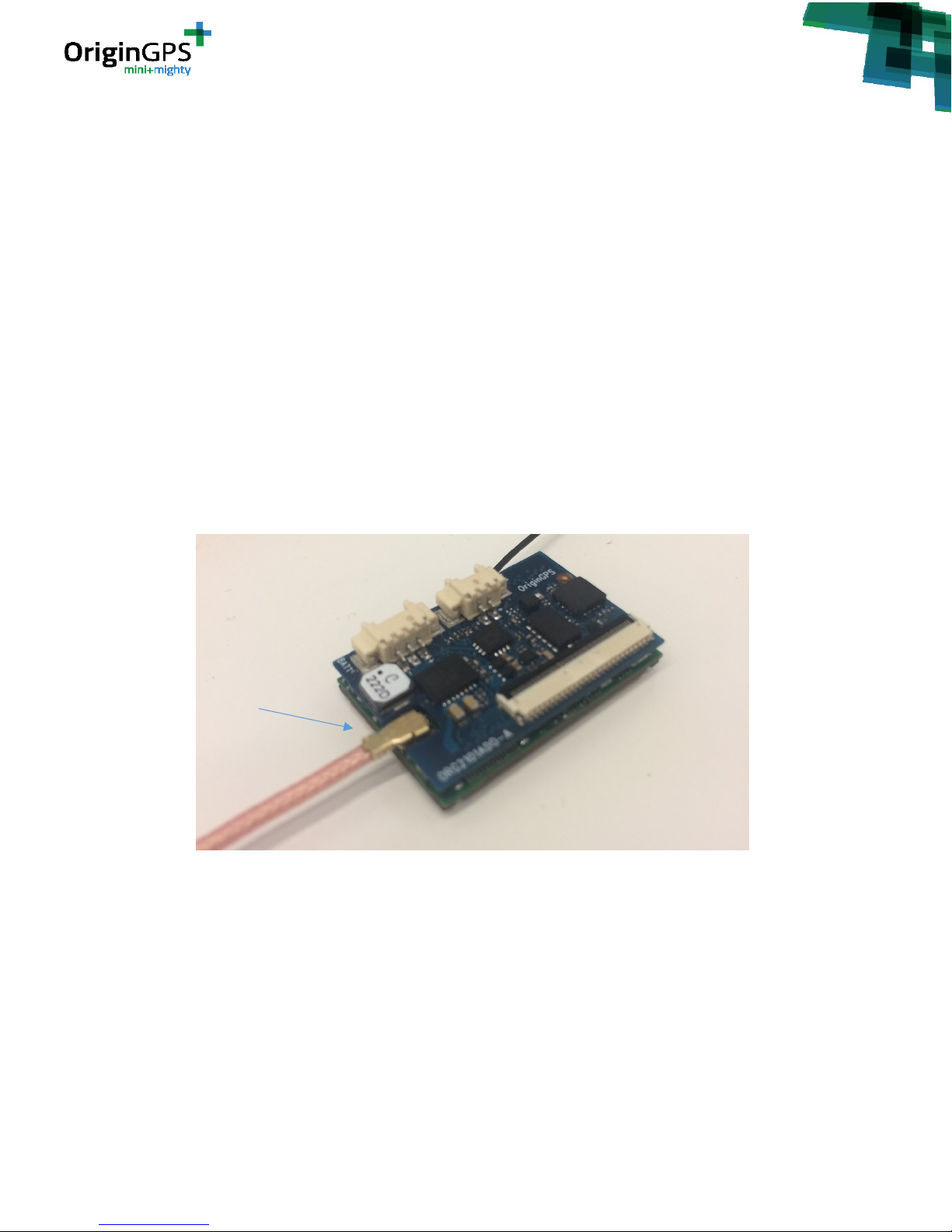
2. Mate ORG2101 with Add-on – connect add-on connectors J1 and J2 to ORG2101 connectors
J1 and J2 as shown in figure 42.
Note – mating ORG2101 with Add-on is unidirectional. Make sure that antenna socket is
aligned with connector J4.
Figure 42 – mati ng Add-on to ORG2101 correctly
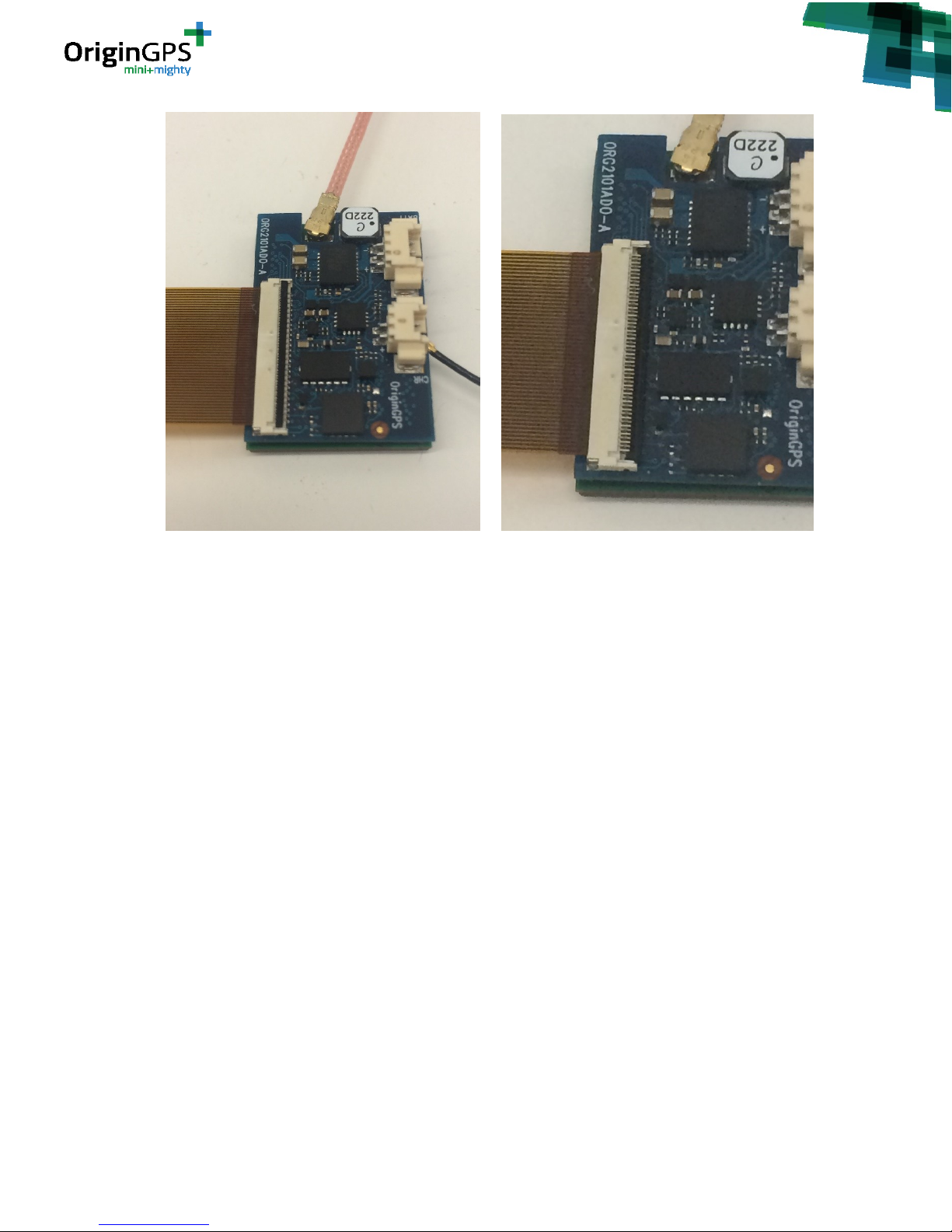
3. Connect assembly to EVK with FFC – place FFC cable inside the FFC connector (J6 in our
example), see figure 43a.
4. Close lever of FFC connector as shown in figure 43b.
GSM Antenna
socket aligned
with antenna
connector
Page 38
- 38 -
OriginIoT EVK User Guide Rev. 1.1 5.13.18
a. b.
Figure 43 – at taching FFC cable to add -on
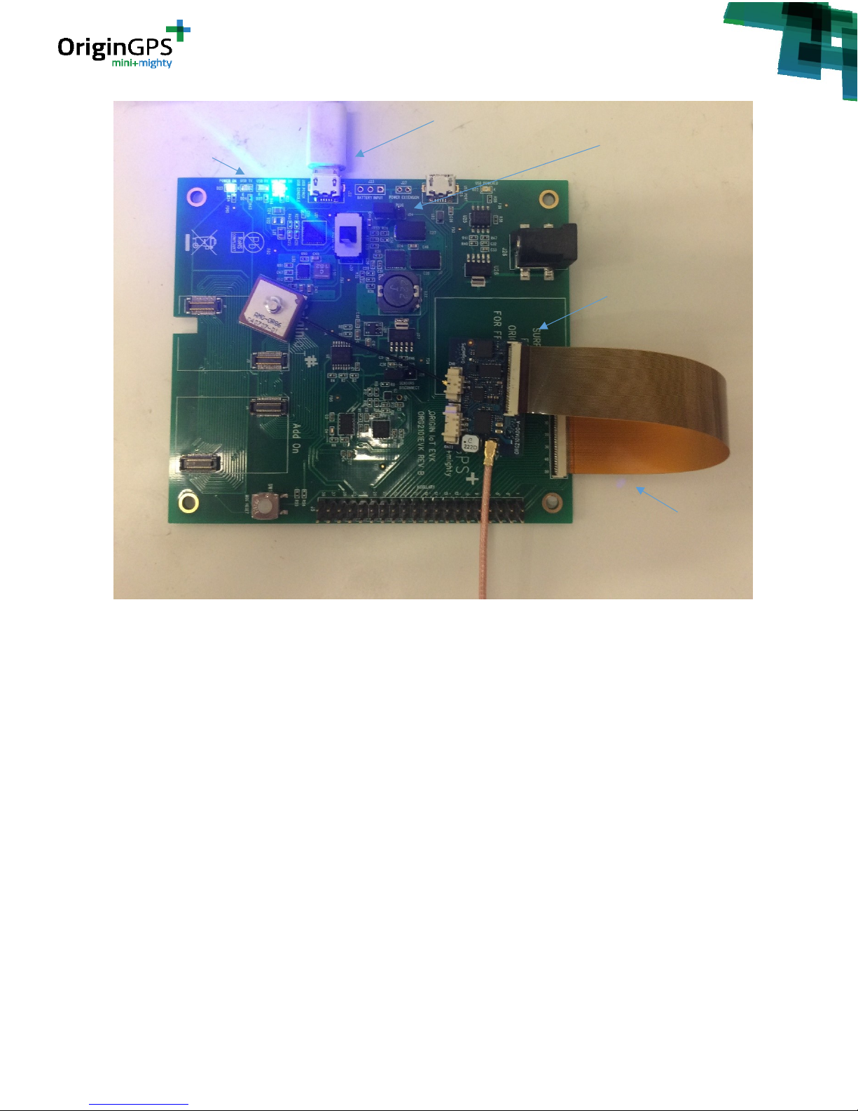
5. In the same manner, connect FFC to FFC connector on the EVK (J6), see figure 44. Pay close
attention to the direction of the FCC.
Note: repeated insertion of FFC, closing and open of actuator can be harmful to the
performance of connector J6.
6. Supply power to EVK by connecting USB cable from PC to J22 and placing Jumper J24 in USB
position, see figure 44.
Page 39
- 39 -
OriginIoT EVK User Guide Rev. 1.1 5.13.18
Figure 43 – attaching FFC cable to EVK
7. Open terminal on your PC and connect to corresponding COM port of the OriginIoT with a
baud rate of 57600 bps.
In Tera Term – go to Setup - > Serial Port (See figure 3a, section 9.2), select the COM port and
set baud rate to 460800 bps. Press “OK”. See figure 3b.
Full communication parameters:
• Baud Rate: 460800
• Data Bits: 8
• Stop Bits: 1
• Flow Control: None
• Parity: None
8. Supply power to OriginIoT via the addon by connecting the battery.
After supplying power to OriginIoT you should see a welcome message and GSM/LTE start-up
messages.
9. While connected, press Enter key in the terminal.
You should see the command line “ORG>” in the terminal window. See Figure 3c, section 9.2.
USB cable
connected to J22
LEDs indicating
USB power and
EVK power
ORG2101, Addon
and antennas
assembly
FCC Molex
150150451
Jumper J24 in
USB position
Page 40

- 40 -
OriginIoT EVK User Guide Rev. 1.1 5.13.18
Now the module can be accessed via the debug console. Please refer to document “OriginIoT
debug console user guide” for the complete list of functions available via the debug console.
Note: you can choose to operate or disconnect the sensors on the EVK using Jumper J28.
 Loading...