

Origin Acoustics thinfit tf34, thinfit tf36, thinfit tf64dt Installation Manual
Installation Manual
ThinFit Collection
Models: TF34
TF36
TF64DT

844·674·4461
TECHSUPPORT@ORIGINACOUSTICS.COM
Table of Contents
Introduction 1
Installation Requirements and Recommendations 1
What’s included 1
Required Tools/Items 1
Optional Tools/Items 2
Dual Tweeter/ Single Stereo Speaker Model TF64DT 2
Speaker Placement 3
Auxiliary Room (2 Speakers) 3
Dedicated Room Home Theater (5 Speakers) 3
Installation 4
1) Installing the Wire 4
Under the Carpet: 5
Behind the Baseboard: 5
Through the Attic: 5
Through the Basement: 5
2) Painting the Grille 6
3) Cutting the Hole 6
4) Connecting the Wires 7
5) Installing the Speaker 7
6) Installing the Grille 7
Troubleshooting 8
Technical Assistance 9
Specifications 11
Warranty 12
Limited Lifetime Warranty 12
Requirements and Warranty Coverage 13
Return Process 13

1WWW.ORIGINACOUSTICS.COM
THINFIT INSTALLATION MANUAL
Introduction
Thank you for purchasing the ThinFit In-Ceiling Speaker. At Origin
Acoustics, we take pride in providing you with a high quality product. All of Origin Acoustics’ speakers are designed to have excellent sound quality, longevity, and a simple installation process.
This instruction booklet covers the necessary information for a
smooth installation of your ThinFit, including: the tools you will
need, step-by-step instructions for installation, troubleshooting
tips for any errors that may occur, and all warranty information. If
for any reason you experience problems or if you have installation
questions please call us at (844) 674-4461. Hours of operation are
8:00am to 5:00pm (Pacific Time), Monday through Friday.
Installation Requirements
and Recommendations
What’s included
• Template
• Speaker
• Grille
Required Tools/Items
• Keyhole or drywall saw
• Speaker wire
• Pencil
• Wire stripper
• Measuring tape
• Screwdriver or drill
2
844·674·4461
TECHSUPPORT@ORIGINACOUSTICS.COM
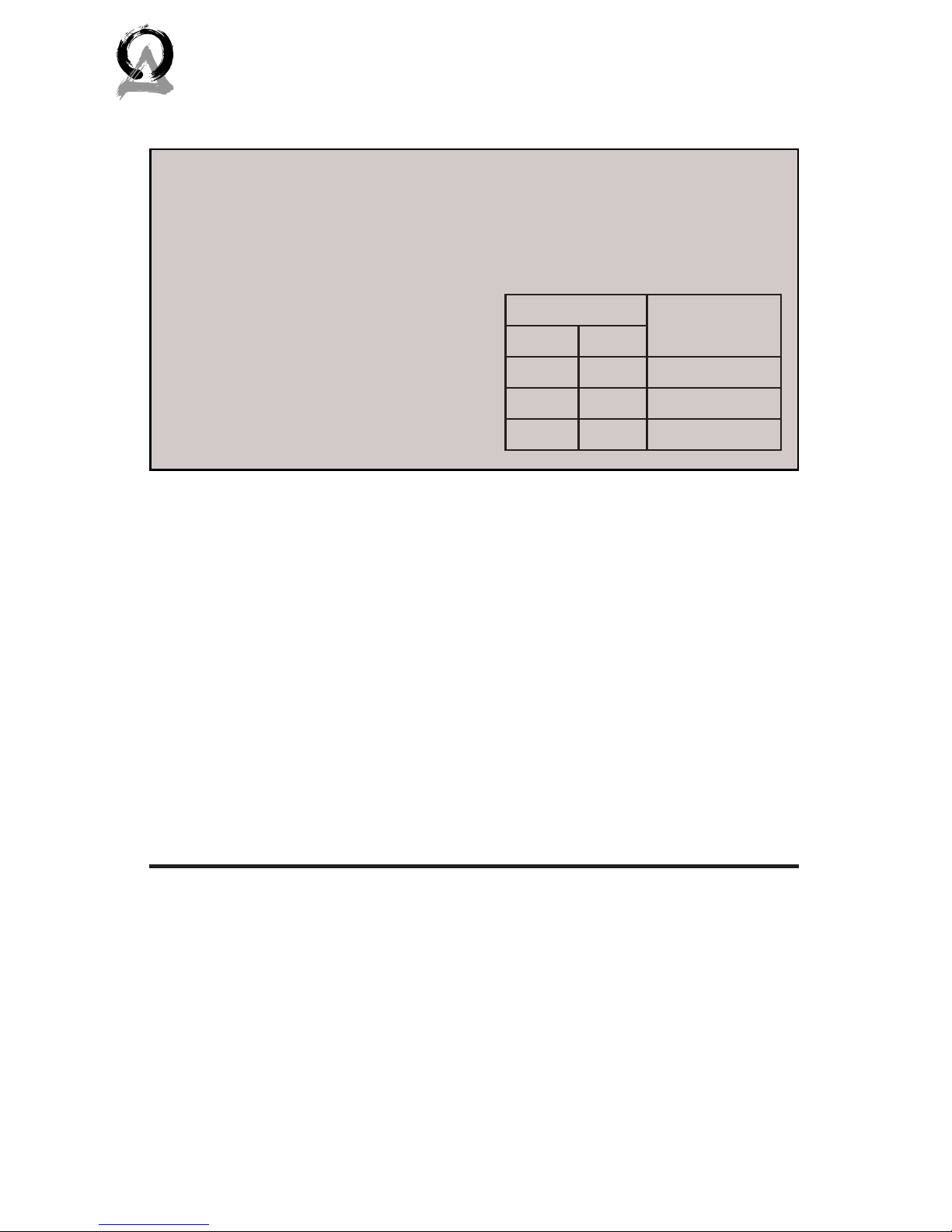
For this setup, use a multi-stranded wiring designed for amplifier
to speaker connections. The
gauge of wire used can have an
impact on the performance of
your speakers and we would
recommend that you choose the
largest wire size that is practical for your installation. Which
gauge to select depends on the
length of wire to be used on any
particular speaker. In general
the shorter the run the smaller
the wire size you can use, however you can never go wrong by
using a thicker gauge.
Wire Length Recommend-
ed Gauge
Feet Meter
0-100 0-30 16
50-150 15-45 14
100+ 30+ 12
Speaker Wire Recommendations
Dual Tweeter/ Single Stereo Speaker Model TF64DT
For the Dual Tweeter model, two channels can be fed into one
speaker: one channel for each tweeter. This setup is ideal for
small rooms such as walk-in closets and bathrooms, as well as
oddly-shaped areas such as hallways. With both le and right
channels in one speaker, only one speaker is needed in smaller
rooms. Or in areas like hallways, both channels can be evenly distributed throughout the area with multiple speakers.
Optional Tools/Items
• Drill with ⅛” (3mm) drill
bit
To check for obstacles in ceiling
• Sti wire (like from a coat
hanger)
To check for obstacles in ceiling
• Stud finder To check for obstacles in ceiling
• Fish tape To route wire through walls
• Can of spray paint For painting the grille
• Can of compressed air For painting the grille

3WWW.ORIGINACOUSTICS.COM
THINFIT INSTALLATION MANUAL
Speaker Placement
Position the two speakers in
the middle of the room, no
less than 6’ (2m) apart. Ideally, the two speakers would be
placed an equal distance from
the listener. If the room has a
lower ceiling, the speakers can
be closer together. Also, if the
speaker placement is intended
for standing (as opposed to
sitting) listeners, the speakers
can be closer together. Figure
3.1 shows the sound coverage
of the room.
For better sound quality, avoid
installing the speakers near
corners.
Dedicated Room Home
Theater (5 Speakers)
The Le Rear (LR) and Right
Rear (RR) speakers should be installed just behind the listener,
one on either side. The Center
Channel (CC) speaker should
be placed above and slightly in
front of the television, with the
Le Front (LF) and Right Front
(RF) speakers placed equidistant to either side.
Auxiliary Room (2 Speakers)
Listener
6’
(2m)
Le Speaker Right Speaker
Figure 3.1: Sound Coverage
Listening Area
6’+
2m+
2’-3’
.5-1m
2’-3’
.5-1m
TV
Left
Speaker
Right
Speaker
Figure 3.2: 2 Speaker Setup
Listening Area
6’-10’
2-3m
2’-3’
.5-1m
TV
LF RF
RRLR
CC
2’-3’
.5-1m
2’-3’
.5-1m
Figure 3.3: 5 Speaker Setup
 Loading...