

Page 1

Installation Manual
V 2.1
Models:
D60
D60DT
D62
D62 DT/SUR
D64
D66
D68
Director 6 Collection
Page 2
1
844·674·4461
WWW.ORIGINACOUSTICS.COM
DIRECTOR 6 INSTALLATION MANUAL
Table of Contents
Introduction 1
Installation Requirements and Recommendations 1
What’s included 1
Required Tools/Items 1
Optional Tools/Items 2
Dual Tweeter Models 2
Surround (Dipole) 3
Stereo (Bipole) 3
Speaker Placement 4
Home Theater (5 Speakers) 4
Installation 5
1) Installing the Wire 5
2) Painting the Grille 7
3) Cutting the Hole 7
4) Installing the InstaMount 8
5) Connecting the Wires 9
6) Installing the Speaker 9
7) Listening Test and Adjustments 10
8) Installing the Grille 11
Troubleshooting 12
Technical Assistance 13
Specifications 15
Warranty 16
Limited Lifetime Warranty 16
Requirements and Warranty Coverage 17
Return Process 17
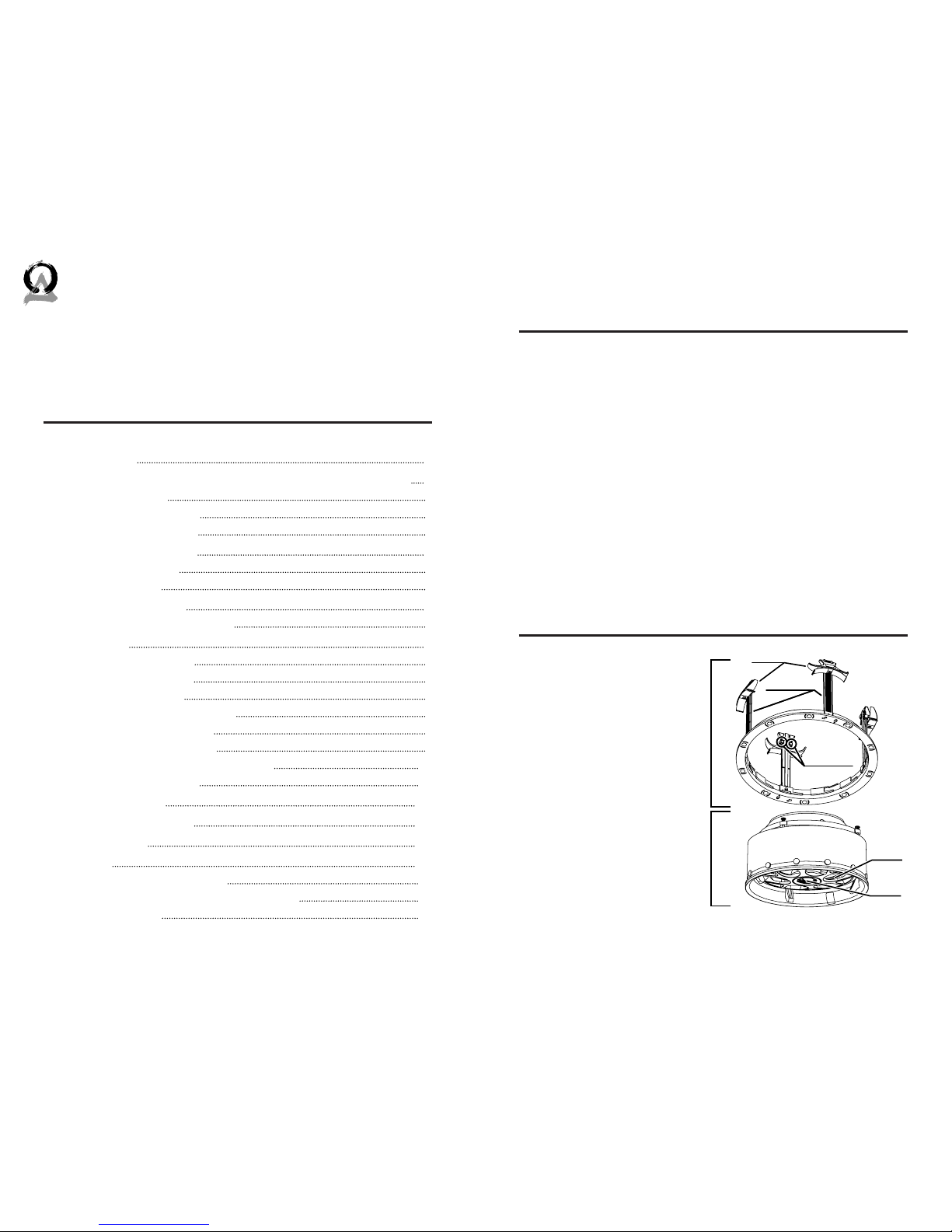
What’s included
• Template
• Speaker
• InstaMount (with 4
detachable ZipClips)
• Grille
Pivong
Woofer
InstaMountSpeaker
ZipClips
Release Tabs
Pivong
Tweeter
ZipClip Rails
Introduction
Thank you for purchasing the Director 6 In-Ceiling Speaker. At Origin Acoustics, we take pride in providing you with a high quality
product. All of Origin Acoustics’ speakers are designed to have excellent sound quality, longevity, and a simple installation process.
This instruction booklet covers the necessary information for a
smooth installation of your Director, including: the tools you will
need, step-by-step instructions for installation, troubleshooting
tips for any errors that may occur, and all warranty information. If
for any reason you experience problems or if you have installation
questions please call us at (844) 674-4461. Hours of operation are
8:00am to 5:00pm (Pacific Time), Monday through Friday.
Installation Requirements
and Recommendations
Required Tools/Items
• Keyhole or drywall saw
• Speaker wire
• Pencil
• Wire stripper
• Measuring tape
• Screwdriver or drill
Page 3

2 3
844·674·4461
WWW.ORIGINACOUSTICS.COM
DIRECTOR 6 INSTALLATION MANUAL
While the D60DT is designed to use only two channels, the D62DT/
SUR can be used for either one channel (surround) or two channels
(stereo). A switch is located on the back of the speaker to select
which mode to use. One of the inputs is labeled for surround. This
is the input that should be used if you’re only using one channel.
Surround (Dipole)
In this mode, one channel is fed into both tweeters to be distributed throughout the area. This way in a multiple-speaker setup, one
speaker can be a dedicated le speaker and another a dedicated
right.
Stereo (Bipole)
In this mode, two channels are fed into the speaker: one channel
for each tweeter. This setup is ideal for small rooms such as walkin closets and bathrooms, as well as oddly-shaped areas such as
hallways. With both le and right channels in one speaker, only
one speaker is needed in smaller rooms. Or in areas like hallways,
both channels can be evenly distributed throughout the area with
multiple speakers.
WARNING
If you are using a dual tweeter speaker in stereo mode (i.e. there
are two wires connected to the speaker: one for the le channel
and one for the right), do not set the switch to surround mode.
This could damage the amplifier.
For this setup, use a multi-stranded wiring designed for amplifier
to speaker connections. The
gauge of wire used can have an
impact on the performance of
your speakers and we would
recommend that you choose the
largest wire size that is practical for your installation. Which
gauge to select depends on the
length of wire to be used on any
particular speaker. In general
the shorter the run the smaller the
wire size you can use, however
you can never go wrong by using
a thicker gauge.
Wire Length Recommended
Gauge
Feet Meter
0-100 0-30 16
50-150 15-45 14
100+ 30+ 12
Speaker Wire Recommendations
Optional Tools/Items
• Drill with ⅛” (3mm) drill
bit
To check for obstacles in ceiling
• Sti wire (like from a coat
hanger)
To check for obstacles in ceiling
• Stud finder To check for obstacles in ceiling
• Fish tape To route wire through walls
• Can of spray paint For painting the grille
• Can of compressed air For painting the grille
Dual Tweeter Models
For the Dual Tweeter models, two channels can be fed into one
speaker: one channel for each tweeter. This setup is ideal for
small rooms such as walk-in closets and bathrooms, as well as
oddly-shaped areas such as hallways. With both le and right
channels in one speaker, only one speaker is needed in smaller
rooms. Or in areas like hallways, both channels can be evenly distributed throughout the area with multiple speakers.
Page 4
4 5
844·674·4461
WWW.ORIGINACOUSTICS.COM
DIRECTOR 6 INSTALLATION MANUAL
Installation
1) Installing the Wire
Strip ¼ to ½ inches (6 to 12
mm) of the insulation o both
ends of the wire. To avoid stray
strands, twist them at the end.
Connect the wire to the amplifier, and make sure the wire
connected to the le speaker
output will be routed to the le
speaker, right output to right
speaker, etc.
You will need a wire that has at least two conductors; one that can be
identified as the positive and the other as the negative. All two conductor
wires have some means of identifying which conductor is which, but at
times this identification may be subtle. It’s crucial that you keep track of
which wire you use for positive (+) and negative (-). Typically if the wires
are colored red and black, the red wire is used for positive and the black
wire is used for negative, but sometimes other colors or patterns are
used. You can choose whichever color of wire you want to be positive and
negative as long as you remain consistent throughout the install.
On both your amplifier and your speaker the connectors will be identified as red for positive and black for negative. It is very important to look
carefully at the speaker wires and be certain that the same wire that is
attached to the positive connector in the amplifier is attached to the positive connector in the speaker.
About Speaker Wire
Speaker Placement
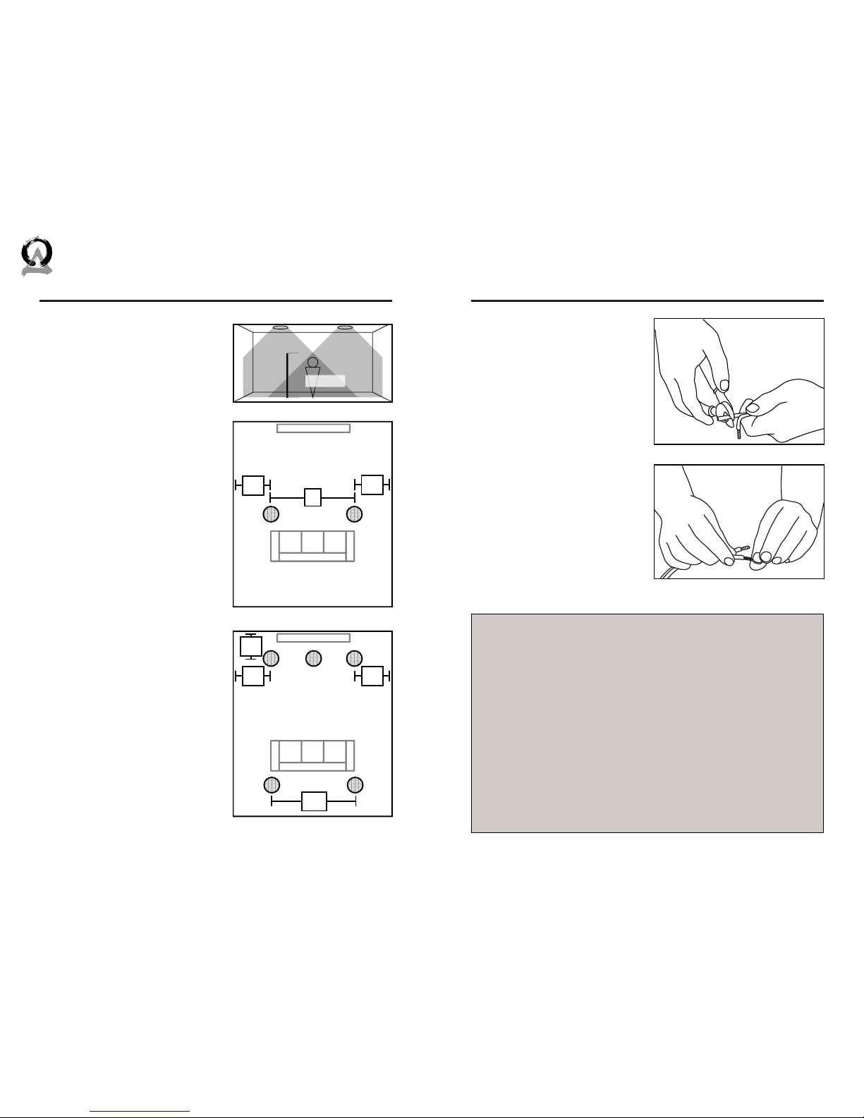
Auxiliary Room (2 Speakers)
Position the two speakers in the
middle of the room, no less than
6’ (2m) apart. Ideally, the two
speakers would be placed an
equal distance from the listener. If
the room has a lower ceiling, the
speakers can be closer together.
Also, if the speaker placement is
intended for standing (as opposed
to sitting) listeners, the speakers
can be closer together. Figure 4.1
shows the sound coverage of the
room.
(The D62 DT/SUR speakers should
be located directly to the side of
the listener, unlike the other models.)
Home Theater (5 Speakers)
The Le Rear (LR) and Right Rear
(RR) speakers should be installed
just behind the listener, one on
either side. The Center Channel
(CC) speaker should be placed
above and slightly in front of the
television, with the Le Front (LF)
and Right Front (RF) speakers
placed equidistant to either side.
Listener
6’
(2m)
Le Speaker Right Speaker
Listening Area
6’+
2m+
2’-3’
.5-1m
2’-3’
.5-1m
TV
Left
Speaker
Right
Speaker
Listening Area
6’-10’
2-3m
2’-3’
.5-1m
TV
LF RF
RRLR
CC
2’-3’
.5-1m
2’-3’
.5-1m
Page 5
6 7
844·674·4461
WWW.ORIGINACOUSTICS.COM
DIRECTOR 6 INSTALLATION MANUAL
Plan how you’ll route the wire
to the desired speaker location.
There are several methods for
routing the wire, and you may
need to combine several of
them.
Under the Carpet:
One option is to li up the carpet and rout “tape wire” under
the carpet.
Behind the Baseboard:
The wire can be routed behind
the baseboard by cutting a groove out of the back of the baseboard, or by buying special baseboard designed for concealing
wires.
Through an Attic, Crawlspace or Basement:
When available, you can route the wire through an attic or crawlspace.
Through walls:
When running wires through a wall, be sure to avoid all obstacles
such as AC wiring, pipes, and ducts.
If these speakers are being
installed in a new home during
construction, the installation
process will be a bit dierent (although much simpler). For these
situations, it’s recommended
you purchase a bracket. Instructions on how to install the
speakers are provided with the
bracket, or can be found on our
website. Visit www.originacoustics.com for more information.
For New Construction
2) Painting the Grille
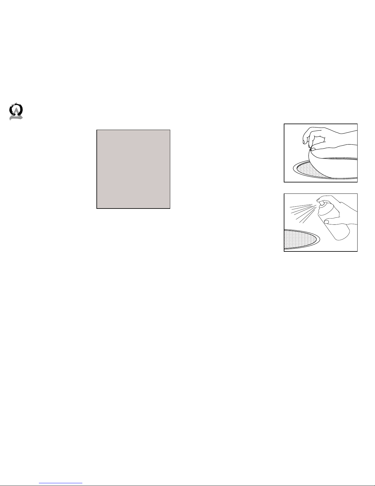
In some situations the speakers
may look better if the color
matched the walls, ceiling, or
trim in the room. This can be
accomplished by painting the
grille. The grille must be painted with spray paint, and most
hardware stores will mix a can
of paint to match whatever color you need.
Before painting, carefully
remove the thin cloth on the
underside of the grille. Lightly
spray the front of the grille
with the paint from a distance,
being careful not to plug any
of the holes. Diluting the paint
with paint thinner will lessen
the risk of filling any holes. If a hole gets plugged use a can of compressed air to open it. Once the paint is dry, put the cloth back on
the grille.
3) Cutting the Hole
When you’ve decided on the locations for all of the speakers,
use the template to trace a circle lightly in pencil where the hole
should be. (If you don’t have a template, check the Specifications
section for cutout sizes.) If you’re unsure on whether there may
be obstacles (such as pipes or studs) where you plan on installing
the speaker, drill a ⅛ inch hole in the center of the circle, then put
a bent coat hanger through the hole to feel around. Use a keyhole
or drywall saw to cut the hole.
Page 6
8 9
844·674·4461
WWW.ORIGINACOUSTICS.COM
DIRECTOR 6 INSTALLATION MANUAL
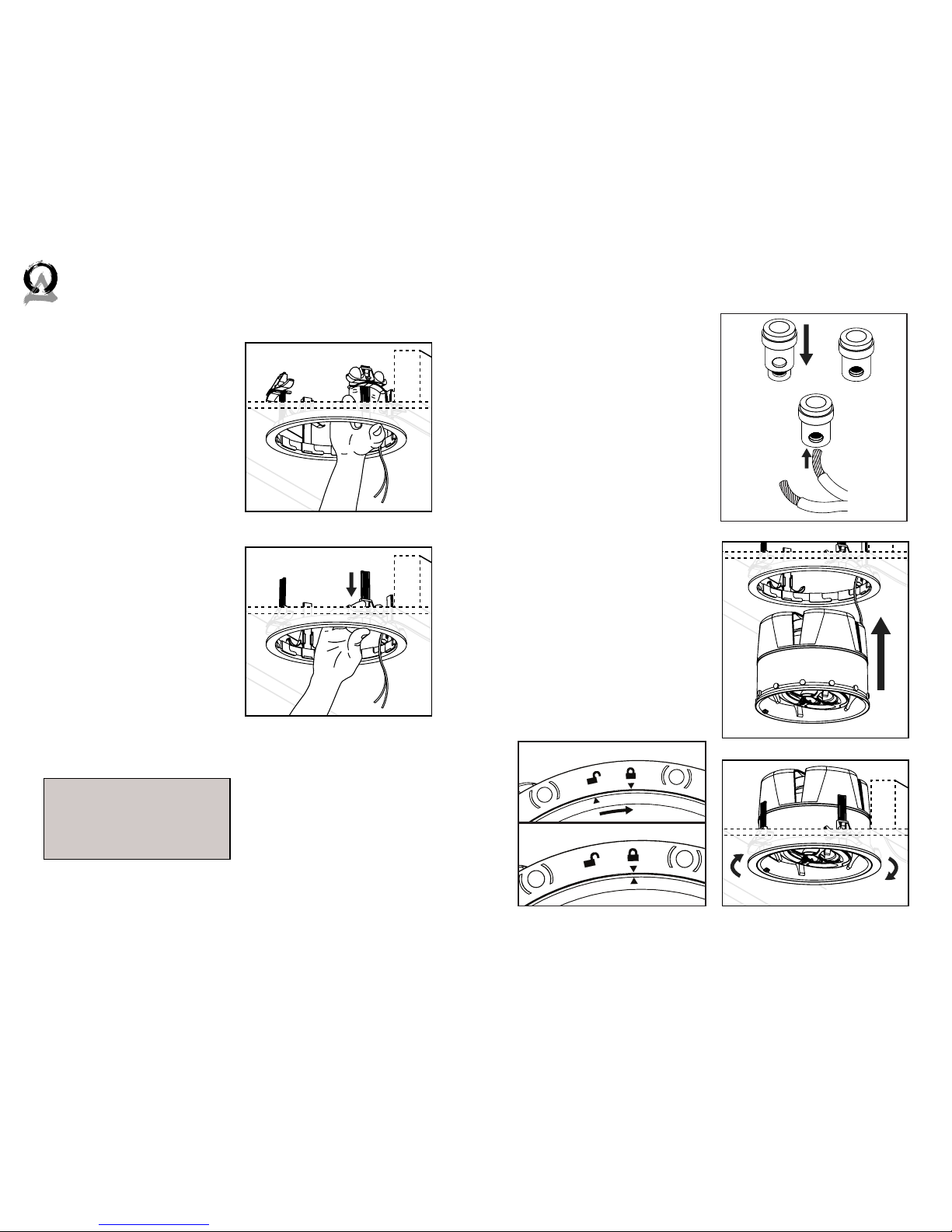
Adjust the ZipClips so that
they’re positioned at the top of
the rail. If they’re not already
there you can do this by pushing the release tabs (or metal
“buttons”) on the inside of the
rail and pulling the ZipClips to
the top of the rails.
Insert the InstaMount into the
hole in the ceiling by gently
bending the ZipClips inward.
Reach inside the InstaMount
and push the ZipClips down so
that the InstaMount is firmly in
place, but not too tight.
If for some reason the InstaMount needs to be removed,
reach inside and push the release tabs to fully remove the
ZipClips. Aer the ZipClips have
been removed, the InstaMount
can be taken out.
4) Installing the InstaMount
5) Connecting the Wires
Insert the wires into the connectors, making sure that the
positive wire is being attached
to the red connection and the
negative wire is being attached
to the black connection. If the
negative and positive wires are
switched, speaker performance
will be drastically impacted.
6) Installing the Speaker
Fit the speaker into the InstaMount, and twist it clockwise
into place. When the arrow on
the speaker lines up with one of
the arrows on the InstaMount,
that means the speaker is tightly in place. Be sure that the ar-
rows line up, otherwise there’s
a risk that the speaker will fall
out of the ceiling.
To watch a video on how to install the InstaMount and speaker, visit our website at:
www.originacoustics.com
Installation Video
Page 7
10 11
844·674·4461
WWW.ORIGINACOUSTICS.COM
DIRECTOR 6 INSTALLATION MANUAL
7) Listening Test and Adjustments
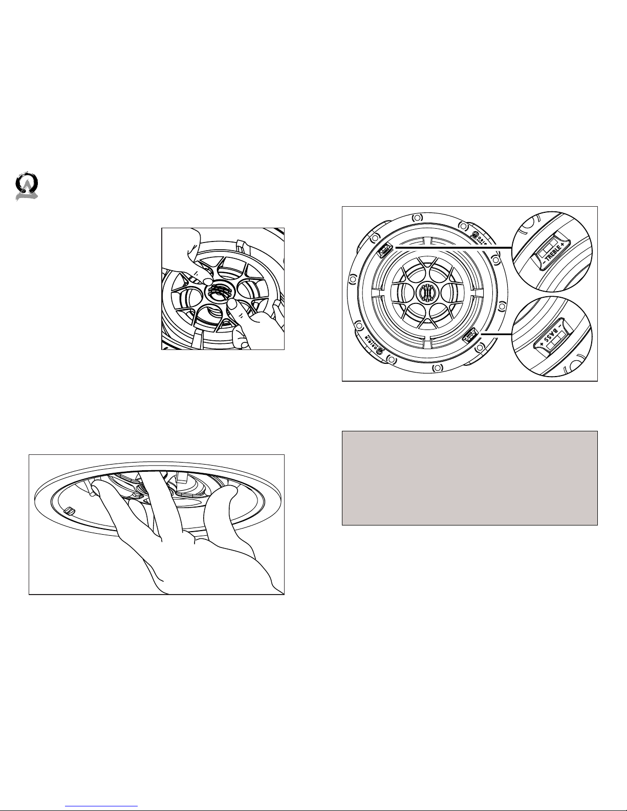
The woofer on the D64, D66,
and D68 and tweeter on all but
the D62 DT/SUR can be pivoted
to direct the sound towards the
listening area. Or for a more
diused surround sound experience, the rear speakers can
be aimed towards the wall. To
aim the tweeter, gently apply
pressure to the rim with your
thumbs to pivot the tweeter.
To aim the woofer, gently apply
pressure to the rim and pivot it
in the desired direction.
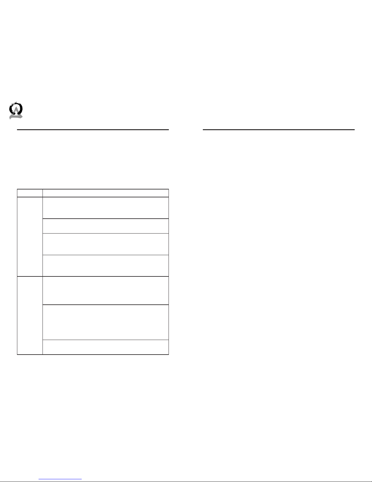
The D66 and D68 have two
switches: one to adjust the treble, and one to adjust the bass.
The D64 only has one switch for
treble.
8) Installing the Grille
Fit the grille over the speaker. The grille uses magnets to be held
in place.
Bass: When a speaker is installed in a corner, the bass is amplified. If this
is the case, it may be best to turn the bass down.
Treble: When a room has a lot of hard surfaces like bare walls and hardwood floors, the treble will reflect o of these surfaces and increase. In
these situations, it may be a good idea to turn the treble down. Alternately, in rooms with carpet and things like curtains, the treble is oen absorbed. If this is the case, it would probably be best to turn up the treble.
Reasons to Adjust Bass and Treble
Page 8
12 13
844·674·4461
TECHSUPPORTORIGINACOUSTICS.COM
WWW.ORIGINACOUSTICS.COM
DIRECTOR 6 INSTALLATION MANUAL
If you have any questions or concerns about installing or using
this product, you can reach us through one of the following methods:
Phone: (844) 674-4461
Hours of operation: 8:00am - 5:00pm (Pacific Time), Mon - Fri
Email: [email protected]
If you are having technical trouble, please include the model number and briefly explain what steps you took to resolve the problem
in your email, or be prepared to answer these questions over the
phone. If you are considering returning the product, it’s required
that you contact Origin Acoustics prior to any return attempts.
This way we can determine if the issue can be resolved without
returning the product, or if needed we can provide instructions
and support for the return process.
If possible, it’s oen good to try to isolate the problem first. For
example, if you’re playing a DVD on a television and there’s no
sound, try connecting an MP3 player to the system to see if that
works. If it does work, then the problem is with the television, DVD
player, or the cables connecting them. If it doesn’t work, the problem will be with the amplifier, speakers, or those cables.
Problem Possible Cause
No Sound
The volume may be turned down or muted. Check
the volume settings on both the amplifier and the
television/computer/CD player/etc.
Make sure the proper source is selected on the amplifier or receiver.
Check the cord connecting the amplifier with the
source. The cord may be damaged or plugged into
the wrong input or output.
Check the wires connecting the amplifier with the
speakers. Make sure they’re connected properly and
not damaged in any way.
Poor Sound Quality
If you hear something like static, or the sound is cutting in and out, check the audio cables. If the problem increases when a cable is being moved, then the
cable is most likely faulty or not connected properly.
Today’s audio systems may have several places to
adjust the volume, for example your MP3 player may
have a volume control, and your amplifier may also
have one. Check to be certain that the volume isn’t
turned up past 80% on any device.
Try changing sources to be certain that the selection
you’ve chosen is a good quality recording.
Troubleshooting Technical AssistanceTechnical AssistanceTroubleshooting
Page 9

14 15
844·674·4461
WWW.ORIGINACOUSTICS.COM
DIRECTOR 6 INSTALLATION MANUAL
SpecificationsSpecifications
Model Number D60 D60DT D62 D62 DT/SUR D64 D66 D68
Part Number SCD20000 SCD2T60000 SCD60200 SCD2T60200 SCD60400 SCD60600 SCD60800
Tweeter Dome Silk Silk Aluminum Aluminum Aluminum Silk DPSD* Silk DPSD*
Tweeter Diameter 1” (25mm) 1” (25mm) 1” (25mm) 1” (25mm) 1” (25mm) 1” (25mm) 1” (25mm)
Woofer Cone Polypropylene Polypropylene IMG IMG IMG Glass Kevlar
Woofer Diameter 6.5” (165mm) 6.5” (165mm) 6.5” (165mm) 6.5” (165mm) 6.5” (165mm) 6.5” (165mm) 6.5” (165mm)
Adjustments N/A N/A N/A N/A Treble Treble & Bass Treble & Bass
Frequency Response 48Hz-20kHz 48Hz-20kHz 48Hz-20kHz 48Hz-20kHz 45Hz-20kHz 43Hz-20kHz 40Hz-20kHz
Impedance 8 ohm 8 ohm 8 ohm 8 ohm 8 ohm 8 ohm 8 ohm
Power Handling 20-100 watts 20-100 watts 25-125 watts 25-125 watts 25-140 watts 25-150 watts 25-160 watts
Sensitivity 86dB ± 3dB 86dB ± 3dB 89dB ± 3dB 89dB ± 3dB 89dB ± 3dB 90dB ± 3dB 90dB ± 3dB
Diameter 9.625” (244mm) 9.625” (244mm) 9.625” (244mm) 9.625” (244mm) 9.625” (244mm) 9.625” (244mm) 9.625” (244mm)
Cutout Diameter 8.75” (222mm) 8.75” (222mm) 8.75” (222mm) 8.75” (222mm) 8.75” (222mm) 8.75” (222mm) 8.75” (222mm)
Mounting Depth** 3.875” (98mm) 3.875” (98mm) 5.375” (135mm) 5.375” (135mm) 3.625” (92mm) 3.625” (92mm) 3.625” (92mm)
*DPSD = Dual Plane Stabilized Diaphragm
**The ZipClip Rails have a mounting depth of 5.3125” (135mm),
but they can be trimmed to be the depth listed above.
Page 10

16 17
844·674·4461
WWW.ORIGINACOUSTICS.COM
DIRECTOR 6 INSTALLATION MANUAL
This warranty may not be valid if the product was purchased
through an unauthorized dealer. This warranty only applies to
the individual that made the original purchase, and it cannot be
applied to other purchases. The purchaser must be prepared to
provide proof of purchase (receipt). This warranty will not be valid if the identifying number or serial number has been removed,
defaced, or altered.
This warranty does not cover the following:
• Accidental damage
• Damage caused by abuse or misuse
• Damage caused by attempted repairs/modifications by
anyone other than Origin Acoustics or an authorized dealer
• Damage caused by improper installation
• Normal wear, maintenance, and environmental issues
• Damage caused by voltage inputs in excess of the rated
maximum of the unit
• Damage inflicted during the return shipment
Origin Acoustics warrants to the original retail purchaser only that
this Origin Acoustics product will be free from defects in materials
and workmanship, provided the speaker was purchased from an
Origin Acoustics authorized dealer.
If the product is determined to be defective, it will be repaired or
replaced at Origin Acoustics’ discretion. If the product must be
replaced yet it is no longer manufactured, it will be replaced with
a model of equal to or greater value that is the most similar to
the original. If this is the case, installing the replacement model
may require mounting modifications; Origin Acoustics will not be
responsible for any such related costs.
Before making any return attempts, it is required that you first
contact Origin Acoustics. Return product to Origin Acoustics
or your dealer, either in person or by mail. It’s preferable if the
product is returned in the original packaging. If this isn’t possible,
the customer is responsible for insuring the shipment for the full
value of the product.
This warranty is in lieu of all other expressed or implied warranties.
Some states do not allow limitations on implied warranties, so this
may not apply depending on the customer’s location. (For more
information, see Magnuson-Moss Warranty Act.)
Return Process
Limited Lifetime Warranty
Requirements and Warranty Coverage
Warranty
Page 11

©2014 Origin Acoustics. All copyrighted, trademarked and
patented elements mentioned herein are the sole property of
Origin Acoustics.
 Loading...