

Origin Acoustics CDi1000, CDi4000, CDi2000 Installation Manual

Crown CDi Amplifier Set-Up
Models:
CDi1000
CDi2000
CDi4000
For Origin Landscape Speakers

1
844·674·4461
TECHSUPPORT@ORIGINACOUSTICS.COM
WWW.ORIGINACOUSTICS.COM
LANDSCAPE CROWN AMPLIFIER INSTALLATION MANUAL
TABLE OF CONTENTS
Introduction 2
Crown Amplifier Ins & Outs 2
Input Connections 2
Unbalanced (Most Common) 2
Balanced 3
Output Connections 4
Terminating The Wires 4
Which Preset To Use? 5
How To Load A Preset 7
How Many Speakers Can Be Run On Each Channel? 7
Technical Assistance 8
2 3
844·674·4461
TECHSUPPORT@ORIGINACOUSTICS.COM
WWW.ORIGINACOUSTICS.COM
LANDSCAPE CROWN AMPLIFIER INSTALLATION MANUAL
INTRODUCTION
Origin Landscape speakers are designed so they can be part of a
70V system or an 8Ω system for smaller installs using a standard
receiver. As part of a 70V system, they will need to be paired with
a Crown CDi amplifier that has been designed to work with our
Landscape speakers. This manual will specifically cover setup
with a Crown CDi amplifier in 70V mode.
• For more detailed information about the Crown CDi amplifier,
refer to the Crown Operation Manual.
• For useful information about the relative merits of dierent
wiring plans you may want to refer to the speaker installation
manual (available on-line).
CROWN AMPLIFIER INs & OUTs
Input connections
Unbalanced (Most Common)
To connect your audio source to the Crown amplifier you will
usually need cables with RCA connectors on the source end and
bare wire on the Landscape amplifier end. The Crown amplifier
channels are labeled CH1 and CH2. Both channels are identical.
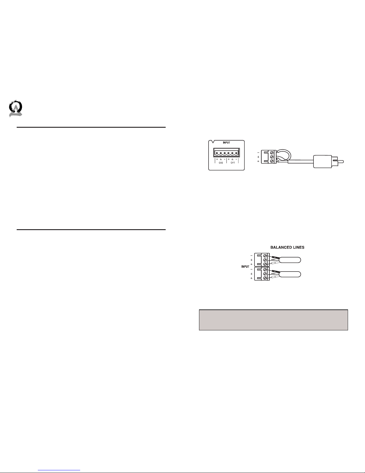
Attach the bare wires from your cable to the Phoenix style connector provided in the amplifier box. Note the location of the positive and ground wires on the Phoenix connector. You must run a
jumper wire from the ground terminal to the negative terminal;
see Figure 1.
Balanced
When using the Origin Landscape series in a commercial installation it might be necessary to connect the amplifier using balanced wiring. Connect the wires from your source equipment to
the Phoenix connector. Be sure to observe proper polarity when
connecting the wires to the Phoenix connector. If your source
equipment uses XLR connectors please confirm the polarity or
pin out of your source equipment before terminating the Phoenix
connector. see figure 2
Shield
CH. 1 Source
CH. 2 Source
CH. 1 Source
CH. 2 Source
Figure 2: Balanced Lines to the Phoenix connectors
CH. 1 Source
CH. 2 Source
Figure 1
WHEN USING BALANCED INPUTS PLEASE CONSULT THE CROWN® AMPLIFIER MANUAL FOR GREATER DETAIL.
NOTE
 Loading...