

Origin Acoustics A2150 Installation Manual
0
RIG IN®
ACOUSTICS
Installatio
n Manual
A2150
2
Channel
Amplifier
Table
ol
Contents
lntroduction
Installation
What's included
Speaker Wire Recommendations
Setup
.............................................................................................................................................
Rack
Individually Protected
Power
lnput
Output
Mounting
.....................................................................................................................................
Important Safety
Specifications
Troubleshooting
........................................................................................................................
Requirements and Recommendations
............................................................................................................
.............................................................................................................
....................................................................................................................................
.................................................................................................................................
lnstructions
...................................................................................................................
...........................................................................................................
Technical Assistance
Warranty
..................................................................................................................................
2
!
......
!
..................................................................
!
2
2
Circuitry
......................................................................
...................................................................
2
2
3
3
4
&
7
................................................................................................
&
&
Introduction
Thank you for purchasing the
Acoustics, we take pride in providing you with a high quality prod-
Origin Acoustics' speakers are designed to have excel-
uct. All
lent sound quality, longevity, and a simple installation process.
This instruction booklet covers the necessary information for a
smooth installation
in the box for this product, the tools you will need, step-by-step
instructions for installation, troubleshooting tips for any errors
that
you experience problems
please call
5:00pm (Pacific Time), Monday through Friday.
of
your amplifier, including: what's included
of
may occur, and all warranty information.
us
at
(844)
674-4461. Hours
A2150
or
if
2 Channel
you have installation questions
operation are
of
Amplifier. At Origin
If for any reason
8:00a~
to
TECHSUPPORT@ORIGINACOUSTICS.COM
844·67 4·4461
CHANNEL
2
AMPLIFIER
INSTRUCTION
MANUAL
Installation
and
What's included
• Amplifier
Mounting plates
•
Removable feet
•
Power cable
•
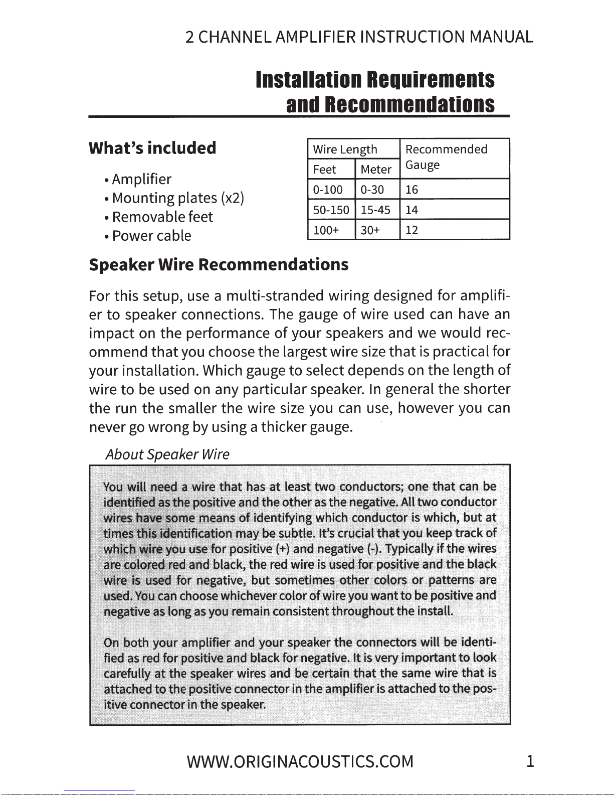
Speaker Wire Recommendations
For this setup,
speaker connections. The gauge
to
er
impact on the performance
ommend
your installation. Which gauge
that
use
you choose the largest wire size
(x2)
a multi-stranded wiring designed for amplifi-
your speakers and we would rec-
of
to
Recommendations
Wire Length
Feet
0-100 0-30
50-150
100+
of
select depends on the length
Requirements
Recommended
Meter
15-45
30+
wire used can have
Gauge
16
14
12
that
practical for
is
an
of
be used on any particular speaker.
wire
the run the smaller the wire size you
never
to
go
About
wrong by using a thicker gauge.
Speaker Wire
general the shorter
In
use, however you
can
can
WWW.ORIGI
NACOUSTICS.COM
1
Rack Mounting
Setup
The
install
unit
comes with
it
in a rack. The feet
two
mounting plates
can
also
be
removed.
that
can
be
used to
Individually Protected Circuitry
Each
if
to
amplifier
is
that
light is off, then
channel
is
individually protected in
case
of
a short. This way,
one channel stops working, the other channel will still continue
function normally. There are 2
that
blue,
that
means there's
indicate the status
means the channel
an
issue and may require attention.
that
channel isn't currently functioning
LED
lights on the front
of
each channel. If
is
functioning normally.
an
of
LED
If
it's red,
And
or
in
light
if
use.
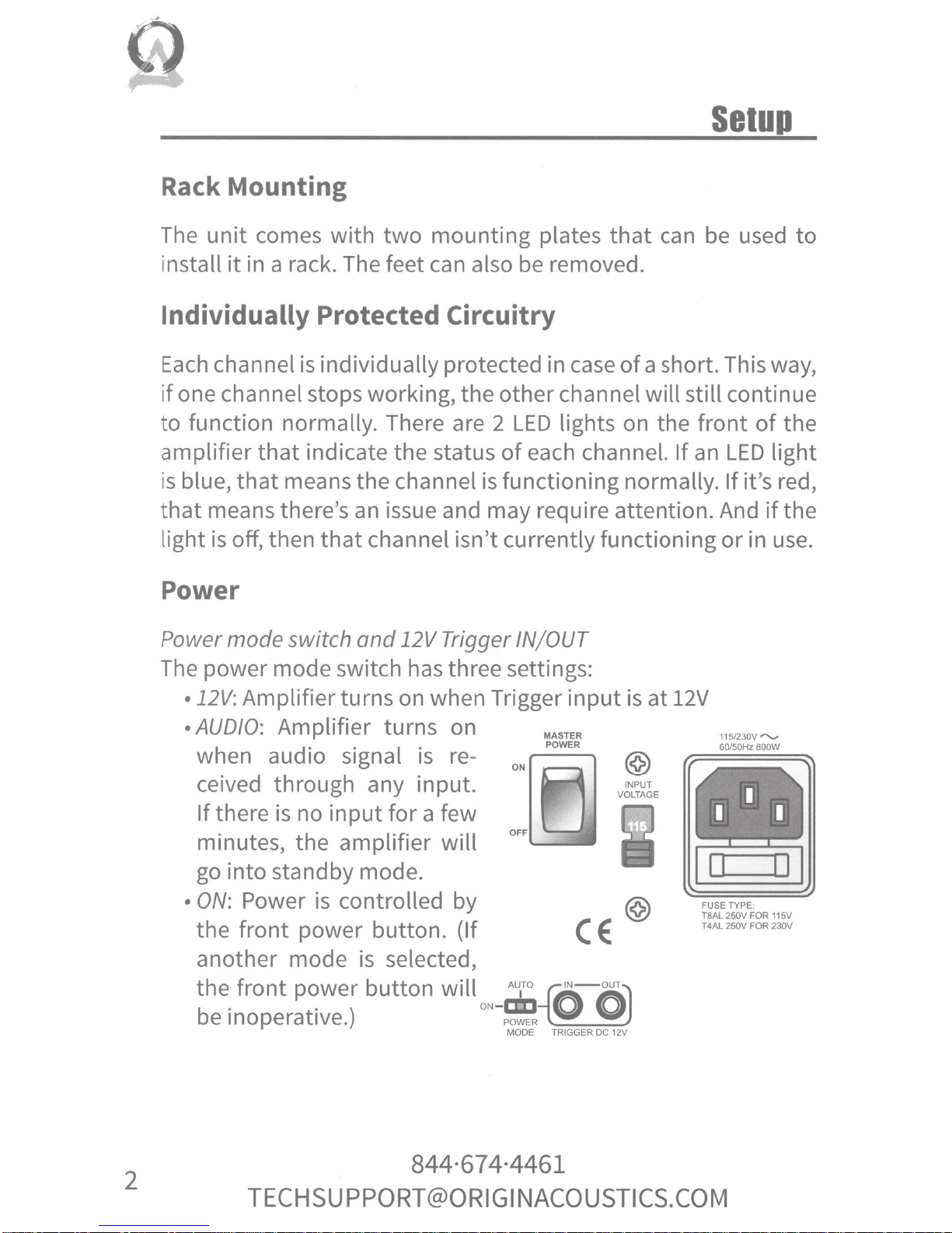
Power
Power
The
mode
switch
and
power mode switch
12V Trigger IN/ OUT
has
three setti
ngs:
the
the
•l2V
• AUDIO: Amplifier turns on
•
: Amplifier turns on when Trigger input
when audio signal
ceived through any
If
there
is
no
input
minutes, the amplifier
go
into standby mode.
ON:
Power
is
controlled by
is
re-
input
for a few
will
the front power button. (If
another mode
the front power button
. . )
b
e InOperatiVe.
is
selected,
will
.
ON
-ca::J
POWER
MAS
TER
POWER
oN~
OFF
Au
•ro
-{4
'N-ouT
0 0
~~~
MODE
TRIGGER
is
at 12V
115/230V
60/50Hz
@
v~ti~l.E
I I
-
0 0
FUSE
TYPE.
TBAL 250V
250V
T4AL
~
DC
12V
I
FOR
FOR
""'-
BOOW
115V
230V
2
TECH
SUP
PO
RT@O
844·67 4·4461
Rl
G I
NACO
USTI
CS.
COM
 Loading...