

Page 1
Installation Manual
A2150
2 Channel Amplifier
Page 2
1
844·674·4461
WWW.ORIGINACOUSTICS.COM
2 CHANNEL AMPLIFIER INSTRUCTION MANUAL
Table of Contents
Installation Requirements and Recommendations 1
What’s included 1
Speaker Wire Recommendations 1
Setup 2
Rack Mounting 2
Individually Protected Circuitry 2
Power 2
Input 3
Output 3
Important Safety Instructions 4
Specifications 6
Troubleshooting 7
Technical Assistance 8
Warranty 8
Introduction
Thank you for purchasing the A2150 2 Channel Amplifier. At Origin
Acoustics, we take pride in providing you with a high quality product. All of Origin Acoustics’ speakers are designed to have excellent sound quality, longevity, and a simple installation process.
This instruction booklet covers the necessary information for a
smooth installation of your amplifier, including: what’s included
in the box for this product, the tools you will need, step-by-step
instructions for installation, troubleshooting tips for any errors
that may occur, and all warranty information. If for any reason
you experience problems or if you have installation questions
please call us at (844) 674-4461. Hours of operation are 8:00am to
5:00pm (Pacific Time), Monday through Friday.
Installation Requirements
and Recommendations
What’s included
• Amplifier
• Mounting plates (x2)
• Removable feet
• Power cable
Speaker Wire Recommendations
For this setup, use a multi-stranded wiring designed for amplifier to speaker connections. The gauge of wire used can have an
impact on the performance of your speakers and we would recommend that you choose the largest wire size that is practical for
your installation. Which gauge to select depends on the length of
wire to be used on any particular speaker. In general the shorter
the run the smaller the wire size you can use, however you can
never go wrong by using a thicker gauge.
Wire Length Recommended
Gauge
Feet Meter
0-100 0-30 16
50-150 15-45 14
100+ 30+ 12
You will need a wire that has at least two conductors; one that can be
identified as the positive and the other as the negative. All two conductor
wires have some means of identifying which conductor is which, but at
times this identification may be subtle. It’s crucial that you keep track of
which wire you use for positive (+) and negative (-). Typically if the wires
are colored red and black, the red wire is used for positive and the black
wire is used for negative, but sometimes other colors or patterns are
used. You can choose whichever color of wire you want to be positive and
negative as long as you remain consistent throughout the install.
On both your amplifier and your speaker the connectors will be identified as red for positive and black for negative. It is very important to look
carefully at the speaker wires and be certain that the same wire that is
attached to the positive connector in the amplifier is attached to the positive connector in the speaker.
About Speaker Wire
Page 3
2 3
844·674·4461
WWW.ORIGINACOUSTICS.COM
2 CHANNEL AMPLIFIER INSTRUCTION MANUAL
Setup
Rack Mounting
The unit comes with two mounting plates that can be used to
install it in a rack. The feet can also be removed.
Individually Protected Circuitry
Each channel is individually protected in case of a short. This way,
if one channel stops working, the other channel will still continue
to function normally. There are 2 LED lights on the front of the
amplifier that indicate the status of each channel. If an LED light
is blue, that means the channel is functioning normally. If it’s red,
that means there’s an issue and may require attention. And if the
light is o, then that channel isn’t currently functioning or in use.
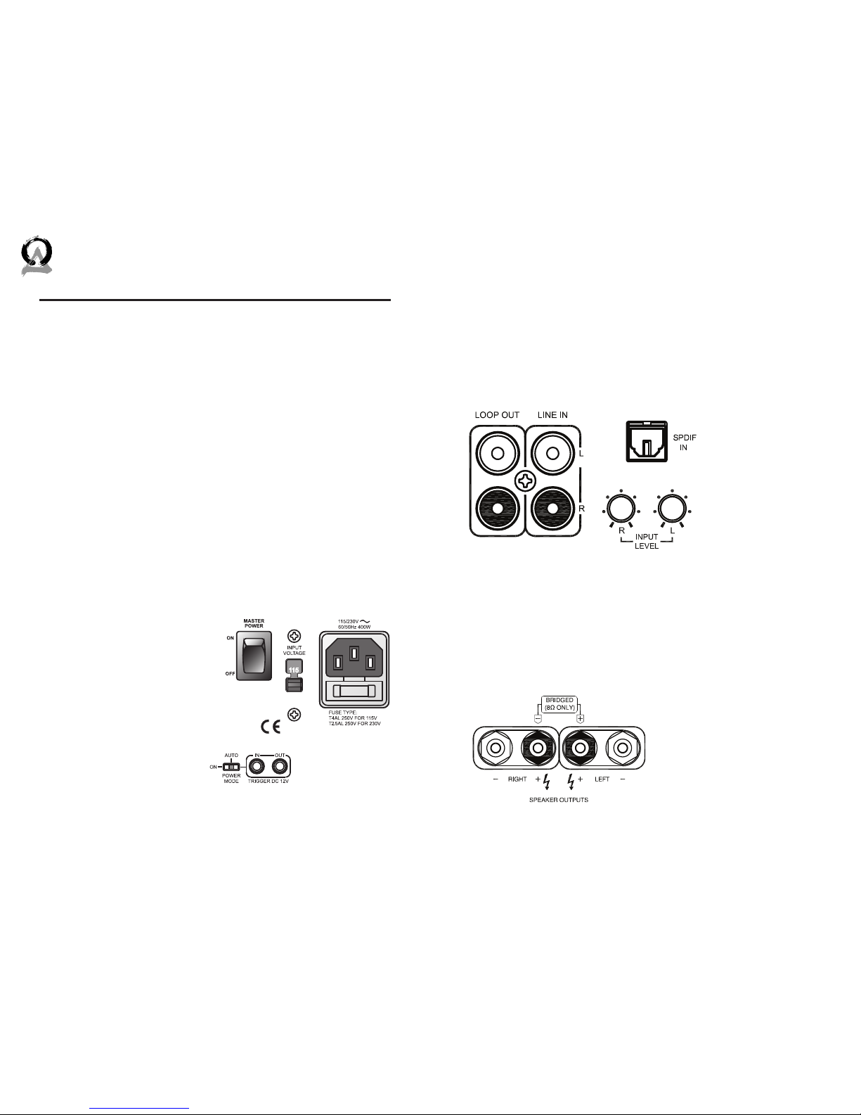
Power
Power mode switch and 12V Trigger IN/OUT
The power mode switch has three settings:
• 12V: Amplifier turns on when Trigger input is at 12V
• AUDIO: Amplifier turns on
when audio signal is received through any input.
If there is no input for a few
minutes, the amplifier will
go into standby mode.
• ON: Power is controlled by
the front power button. (If
another mode is selected,
the front power button will
be inoperative.)
Input
LINE IN
Basic input for channels 1 and 2
(le and right). If you would like
to use an S/PDIF cable, it can be
connected in the SPDIF INPUT.
LOOP OUT
If you need sound through
more speakers than this amplifier can support, you can
use the “LOOP OUT” output to
connect a second amplifier.
INPUT LEVEL
The maximum gain
can be set for each
channel.
/
BRIDGED IN
Output
SPEAKER OUTPUTS
Connect the speakers to the
outputs as labeled. (Be careful
not to switch the positive and
negative connections.)
BRIDGED Output
In some setups you may want
to power a speaker by combining the two outputs. To do
this, first unplug the power
cable. Set the bridge switch to
“BRIDGED”. Connect the speaker wires to the outputs labeled
BRIDGED. (Be careful not to
switch the positive and negative connections.) Connect the
source output to the white LINE
IN input.
/
BRIDGED IN
/
BRIDGED IN
Page 4
4 5
844·674·4461
WWW.ORIGINACOUSTICS.COM
2 CHANNEL AMPLIFIER INSTRUCTION MANUAL
Important Safety Instructions
WARNING: To reduce the risk of fire or electric shock, do not expose this apparatus to rain or moisture.
• Read these instructions.
• Keep these instructions.
• Heed all warnings.
• Follow all instructions.
• Do not use this apparatus near water.
• Clean only with dry cloth.
• Do not block any ventilation openings. Install in accordance
with the manufacturer’s instructions.
• Do not install near any heat sources such as radiators, heat
registers, stoves, or other apparatus (including amplifiers)
that produce heat.
• Do not defeat the safety purpose of the polarized or grounding-type plug. A polarized plug has two blades with one wider
than the other. A grounding type plug has two blades and a
third grounding prong. The wide blade or the third prong are
provided for your safety. If the provided plug does not fit into
your outlet, consult an electrician for replacement of the obsolete outlet.
• Protect the power cord from being walked on or pinched
particularly at plugs, convenience receptacles, and the point
where they exit from the apparatus.
• Only use attachments/accessories specified by the manufacturer.
• Use only with the cart, stand, tripod, bracket, or table specified by the manufacturer, or sold with the apparatus. When
a cart is used, use caution when moving the cart/apparatus
combination to avoid injury from tip-over.
• Unplug this apparatus during lightning storms or when unused for long periods of time.
• Refer all servicing to qualified service personnel. Servicing is
required when the apparatus has been damaged in any way,
such as power-supply cord or plug is damaged, liquid has
been spilled or objects have fallen into the apparatus, the
apparatus has been exposed to rain or moisture, does not
operate normally, or has been dropped.
• The MAINS plug or an appliance coupler is used as the disconnect device, so the disconnect device shall remain readily
operable.
• This apparatus has been designed with Class-I construction
and must be connected to a mains socket outlet with a protective earthing connection (the third grounding prong).
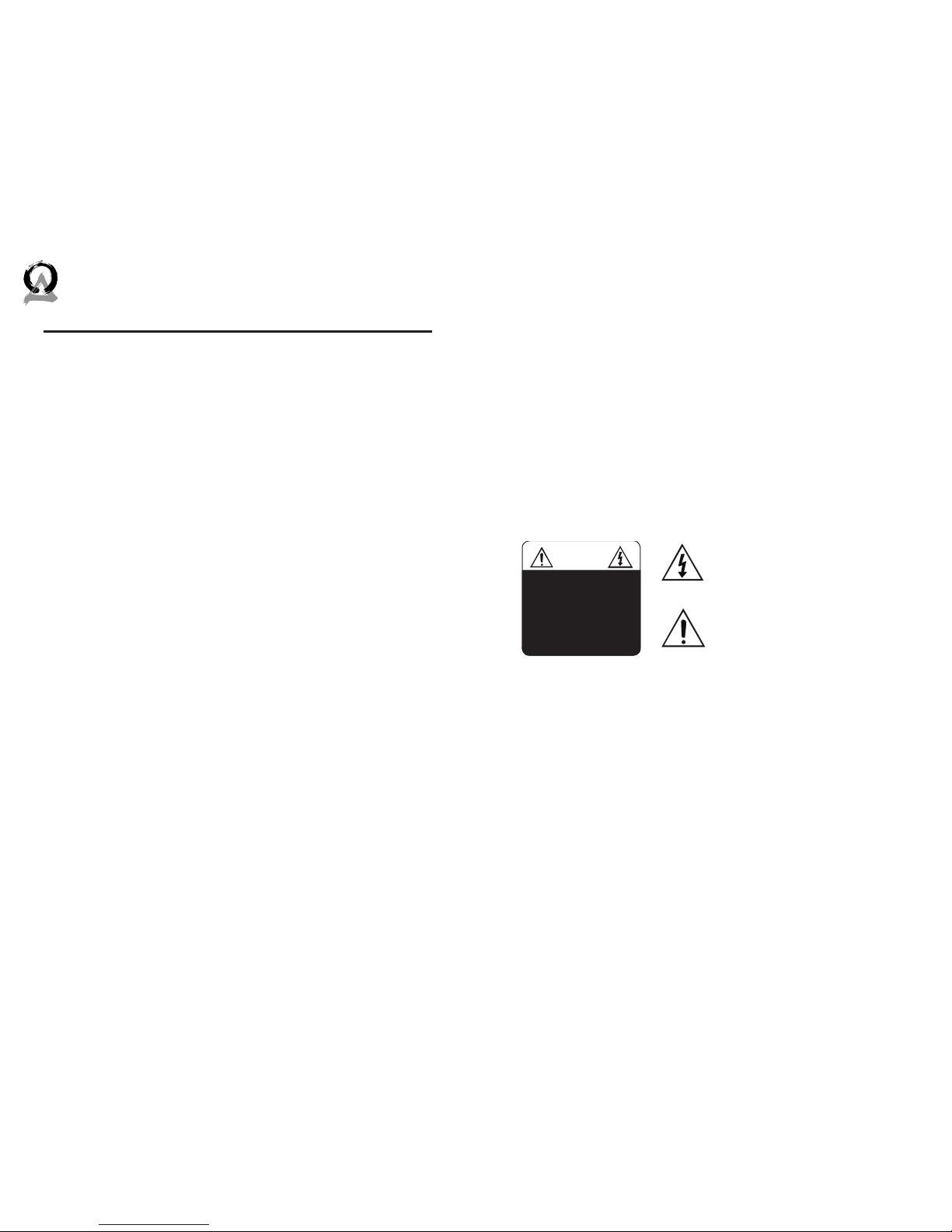
The lightning flash with arrowhead symbol, within an equilateral triangle, is intended to
alert the user to the presence of
uninsulated dangerous voltage
within the product’s enclosure
that may be of suicient magnitude to constitute a risk of
electric shock to persons.
The exclamation point within an equilateral triangle is intended
to alert the user to the presence of important operating and maintenance (servicing) instructions in the literature accompanying
the appliance.
CAUTION
CAUTION: TO REDUC E THE RISK OF
ELEC TRICAL SHOCK.
DO NOT REMOVE COVER. NO USER
SERVICEABLE PARTS INSIDE.
REFER SERVICING TO QUALIFIED
SERVICE PERSONNEL.
Page 5
6 7
844·674·4461
WWW.ORIGINACOUSTICS.COM
2 CHANNEL AMPLIFIER INSTRUCTION MANUAL
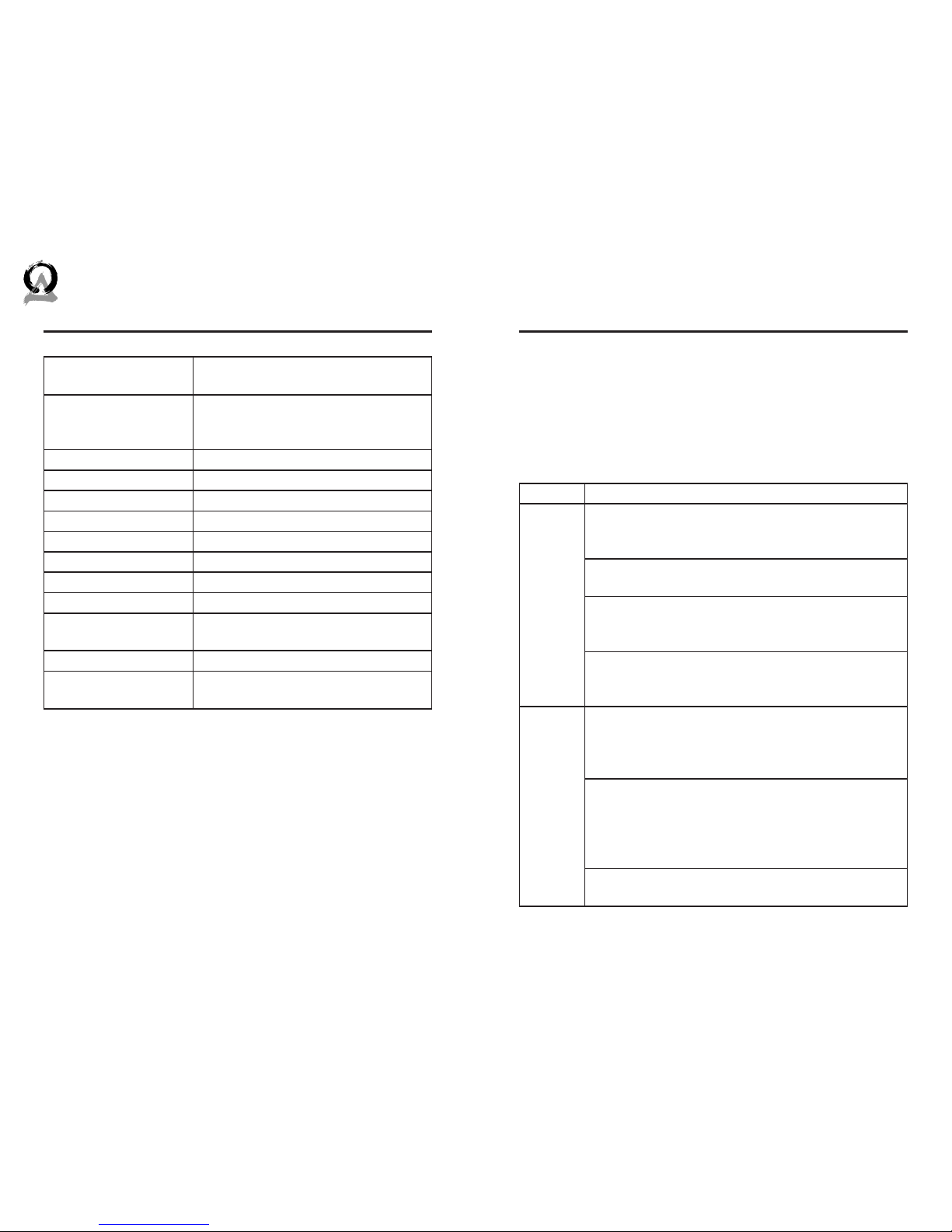
Specifications
Continuous Power
Both Channels Driven
150 watts RMS at 4 ohms, 95 watts
RMS at 8 ohms
Bridged Power Output
Both Channels Driven
280 Watts per channel RMS at 8 ohms
(Note: Maintain 8 ohm minimum
when using bridge mode)
Input Sensitivity 1000mV
Input Impedance 20,000 ohms
12 Volt Trigger Input 12V DC; 10K Ohms
12 Volt Trigger Output 12V DC; 10mA
S/N ratio 95 dB
Frequency Response 20 Hz to 20 kHz
Distortion (Un-bridged) 0.1% THD 20 Hz-20 kHz
Distortion (Bridged) 0.1% THD 20 Hz-20 kHz
Dimensions 17.7”W x 3.5”H x 13.4”D (450W x 89H x
340D mm)
Weight 13.1 lb (5.94 kg)
Certification Meets FCC Part 15, ETL Listed and
tested under UL/EN60065
Problem Possible Cause
No Sound
The volume may be turned down or muted. Check
the volume settings on both the amplifier and the
television/computer/CD player/etc.
Make sure the proper source is selected on the amplifier or receiver.
Check the cord connecting the amplifier with the
source. The cord may be damaged or plugged into
the wrong input or output.
Check the wires connecting the amplifier with the
speakers. Make sure they’re connected properly and
not damaged in any way.
Poor Sound Quality
If you hear something like static, or the sound is cutting in and out, check the audio cables. If the problem increases when a cable is being moved, then the
cable is most likely faulty or not connected properly.
Today’s audio systems may have several places to
adjust the volume, for example your MP3 player may
have a volume control, and your amplifier may also
have one. Check to be certain that the volume isn’t
turned up past 80% on any device.
Try changing sources to be certain that the selection
you’ve chosen is a good quality recording.
Troubleshooting
If possible, it’s oen good to try to isolate the problem first. For
example, if you’re playing a DVD on a television and there’s no
sound, try connecting an MP3 player to the system to see if that
works. If it does work, then the problem is with the television, DVD
player, or the cables connecting them. If it doesn’t work, the problem will be with the amplifier, speakers, or those cables.
Page 6

8 9
844·674·4461
WWW.ORIGINACOUSTICS.COM
2 CHANNEL AMPLIFIER INSTRUCTION MANUAL
Requirements and Warranty Coverage
This warranty may not be valid if the product was purchased
through an unauthorized dealer. This warranty only applies to
the individual that made the original purchase, and it cannot be
applied to other purchases. The purchaser must be prepared to
provide proof of purchase (receipt). This warranty will not be valid if the identifying number or serial number has been removed,
defaced, or altered.
This warranty does not cover the following:
• Accidental damage
• Damage caused by abuse or misuse
• Damage caused by attempted repairs/modifications by anyone other than Origin Acoustics or an authorized dealer
• Damage caused by improper installation
• Normal wear, maintenance, and environmental issues
• Damage caused by voltage inputs in excess of the rated maximum of the unit
• Damage inflicted during the return shipment
Return Process
Before making any return attempts, it is required that you first
contact Origin Acoustics. Return product to Origin Acoustics
or your dealer, either in person or by mail. It’s preferable if the
product is returned in the original packaging. If this isn’t possible,
the customer is responsible for insuring the shipment for the full
value of the product.
This warranty is in lieu of all other expressed or implied warranties.
Some states do not allow limitations on implied warranties, so this
may not apply depending on the customer’s location. (For more
information, see Magnuson-Moss Warranty Act.)
Technical Assistance
If you have any questions or concerns about installing or using
this product, you can reach us through one of the following methods:
Phone: (844) 674-4461
Hours of operation: 8:00am - 5:00pm (Pacific Time), Mon - Fri
Email: [email protected]
If you are having technical trouble, please include the model number and briefly explain what steps you took to resolve the problem
in your email, or be prepared to answer these questions over the
phone. If you are considering returning the product, it’s required
that you contact Origin Acoustics prior to any return attempts.
This way we can determine if the issue can be resolved without
returning the product, or if needed we can provide instructions
and support for the return process.
Warranty
Two-Year Warranty
Origin Acoustics warrants to the original retail purchaser only that
this Origin Acoustics product will be free from defects in materials
and workmanship, provided the speaker was purchased from an
Origin Acoustics authorized dealer.
If the product is determined to be defective, it will be repaired or
replaced at Origin Acoustics’ discretion. If the product must be
replaced yet it is no longer manufactured, it will be replaced with
a model of equal to or greater value that is the most similar to
the original. If this is the case, installing the replacement model
may require mounting modifications; Origin Acoustics will not be
responsible for any such related costs.
Page 7

©2014 Origin Acoustics. All copyrighted, trademarked and
patented elements mentioned herein are the sole property of
Origin Acoustics.
 Loading...