

Page 1

ORIENTEK T40
Optical Fiber Fusion Splicer
User
’
s Manual
Page 2

i
Safety
Safety
Safety
Safety Summary
Summary
Summary
Summary
The following general safety precautions must be observed
during all phases of operation of this instrument. Failure to
comply with these precautions or with specific warnings
elsewhere in this manual violates safety standards of design,
manufacture, and intended use of the instrument. Our company
assumes no liability for the customer’s failure to comply with
these requirements.
ENVIRONMENTAL
ENVIRONMENTAL
ENVIRONMENTAL
ENVIRONMENTAL CONDITIONS
CONDITIONS
CONDITIONS
CONDITIONS
Refer to the specifications in chapter 3 for operating and
storage environment.
BEFORE
BEFORE
BEFORE
BEFORE APPLYING
APPLYING
APPLYING
APPLYING POWER
POWER
POWER
POWER
Refer to the specifications for the voltage in chapter 3.
Verify
that the product is set to match the available voltage, and all
safety precautions are taken.
DO
DO
DO
DO NOT
NOT
NOT
NOT OPERATE
OPERATE
OPERATE
OPERATE IN
IN
IN
IN EXPLOSIVE
EXPLOSIVE
EXPLOSIVE
EXPLOSIVE ATMOSPHERE
ATMOSPHERE
ATMOSPHERE
ATMOSPHERE
Do not operate the instrument in the presence of flammable
gases or fumes.
DO
DO
DO
DO NOT
NOT
NOT
NOT REMOVE
REMOVE
REMOVE
REMOVE THE
THE
THE
THE INSTRUCTMENT
INSTRUCTMENT
INSTRUCTMENT
INSTRUCTMENT COVER
COVER
COVER
COVER
Operating personnel must not remove instrument covers, other
than as explained in this guide. Component replacement and
internal adjustments must be made only by qualified service
personnel.
Page 3

ii
General
General
General
General Safety
Safety
Safety
Safety Information
Information
Information
Information
AC/DC
AC/DC
AC/DC
AC/DC Adapter/Charger
Adapter/Charger
Adapter/Charger
Adapter/Charger
The following voltage requirements must be met : 1 2.9V to
14V
,
4 .5A, positive core. Use of higher voltages may damage the
product. The adapter accepts from 100V to 240V, 50Hz to
60Hz.
Battery
Battery
Battery
Battery
1. Use lithium battery. Use of o ther batter ies may damage the
product and compromise the user’s safety.
2.. Do not short circuit the battery by directly connecting the
metal terminals. Be certain that no metal objects such as
coins, paper clips and so on touch the terminals.
Operation
Operation
Operation
Operation of
of
of
of fiber
fiber
fiber
fiber fusion
fusion
fusion
fusion splicer
splicer
splicer
splicer
1. When the following situation happened , please turn off the
instrument and cut off the power, otherwise the instrument
would be damaged.
Liquid or eye - winker entered the instrument.
Instrument was impacted strongly.
2. There are no parts which need maintenance , don ’ t
disassembly the instrument.
Page 4

iii
Caution
Caution
Caution
Caution
AC/DC
AC/DC
AC/DC
AC/DC Adapter/Charger
Adapter/Charger
Adapter/Charger
Adapter/Charger
Please use the AC/DC adapter/charger that supplied by our
company. Use of another type of AC/DC adapter can damage
the instrument.
Battery
Battery
Battery
Battery
1. If your battery is new or has been in storage for a long time,
you may need to charge it two or three times to achieve
optimum performance levels.
2. For the best battery performance and accuracy of the fuel
gauge, completely discharge the battery, then make a
complete fast charge cycle (non-operating), and
completely discharge the battery again.
3. You must ensure that the charging cycle is not interrupted
by a battery discharge, and the discharge cycle is not
interrupted by battery charging.
4. Storage temperature range (the storage time is longer than
six months ) is: -20 ° C to 45 ° C. Storage temperature
range(the storage time is shorter than or up to six months )
is : -20 ° C to 60 ° C.
5. To insure safe charging, the temperature should keep 0 ° C ~
40 ° C inside the OFFS. If the temperature is exceeded, the
charging would be stopped.
Page 5

iv
LCD
LCD
LCD
LCD
1. Don ’ t use any sharp device to press the touch screen.
2. Don't pollute touch screen with any organic compound or
organic contaminant such as heptanes, ethanol, toluene,
cello solve acetate, hydrochloric acid, motor oil, diesel
fuel etc .
3. Clean the touch screen with a soft, non-abrasive cloth
dampened with glass cleaner.
Fiber
Fiber
Fiber
Fiber Fusion
Fusion
Fusion
Fusion Splice
Splice
Splice
Splice Use
Use
Use
Use Caution
Caution
Caution
Caution
1. This OFFS can only fusion splice quartz fiber, please don ’ t
apply it to other type fibers.
2. Please keep the shield closed in most time in dusty air to
avoid massing dust.
3. When you move to environment of high temperature,
please avoid condensing.
4. Annual maintenance is suggested to keep the performance.
5. The OFFS is fine calibrated instrument, please avoid
vibration and impact.
Page 6

v
Maintenance
Maintenance
Maintenance
Maintenance and
and
and
and Warranty
Warranty
Warranty
Warranty
Our company warrants this instrument against defects in
material and workmanship for 18 months , battery for 3 months
from the date of original shipment. From the date of original
shipment. The warranty can become null and void if:
1. The instrument has been misused, neglected, or damaged
by accident.
2. The instrument has discharged more than 3000 times. The
instrument has been tampered with, repaired, or worked
upon by unauthorized individuals.
3. Case screws or seals, other than those specified in this
guide , have been removed.
If the instrument must be returned to our company, Please pack
the equipment in its original shipping material, be sure to write
a tag showing owner, return address, telephone and the type of
service required. If you do not have the original shipping box,
you must use an appropriate shock absorbing material,
otherwise the instrument can be damaged, and the warranty can
become null and void.
Our company reserves the right to make changes in the design
or construction of any of its products at any time without
incurring any obligation to make changes whatsoever on units
purchased. Accessories, including but not limited to fuses, pilot
lamps and batteries used with this product are not covered by
this warranty.
Page 7

Contents
Contents
Contents
Contents
Safety
Safety
Safety
Safety Summary
Summary
Summary
Summary ...............................................................
...............................................................
...............................................................
............................................................... i
i
i
i
General
General
General
General Safety
Safety
Safety
Safety Information
Information
Information
Information ............................................
............................................
............................................
............................................ ii
ii
ii
ii
Caution
Caution
Caution
Caution ...........................................................................
...........................................................................
...........................................................................
........................................................................... iii
iii
iii
iii
Maintenance
Maintenance
Maintenance
Maintenance and
and
and
and Warranty
Warranty
Warranty
Warranty ............................................
............................................
............................................
............................................ v
v
v
v
Contents
Contents
Contents
Contents .........................................................................
.........................................................................
.........................................................................
......................................................................... vi
vi
vi
vi
Chapter
Chapter
Chapter
Chapter 1
1
1
1 General
General
General
General Information
Information
Information
Information ...................................
...................................
...................................
................................... 1
1
1
1
Chapter
Chapter
Chapter
Chapter 2
2
2
2 Special
Special
Special
Special Terms
Terms
Terms
Terms ..............................................
..............................................
..............................................
.............................................. 2
2
2
2
Chapter
Chapter
Chapter
Chapter 3
3
3
3 Technical
Technical
Technical
Technical Parameters
Parameters
Parameters
Parameters .................................
.................................
.................................
................................. 5
5
5
5
Chapter
Chapter
Chapter
Chapter 4
4
4
4 Configuration
Configuration
Configuration
Configuration ..............................................
..............................................
..............................................
.............................................. 7
7
7
7
Chapter
Chapter
Chapter
Chapter 5
5
5
5 Structure
Structure
Structure
Structure and
and
and
and Panel
Panel
Panel
Panel ....................................
....................................
....................................
.................................... 8
8
8
8
Chapter
Chapter
Chapter
Chapter 6
6
6
6 Installation
Installation
Installation
Installation and
and
and
and Adjustment
Adjustment
Adjustment
Adjustment .....................
.....................
.....................
..................... 14
14
14
14
Chapter
Chapter
Chapter
Chapter 7
7
7
7 Basic
Basic
Basic
Basic Operation
Operation
Operation
Operation ........................................
........................................
........................................
........................................ 16
16
16
16
Chapter
Chapter
Chapter
Chapter 8
8
8
8 Maintenance
Maintenance
Maintenance
Maintenance ..............................................
..............................................
..............................................
.............................................. 27
27
27
27
APPENDIX
APPENDIX
APPENDIX
APPENDIX A
A
A
A
Test
Test
Test
Test
and
and
and
and Adjustment
Adjustment
Adjustment
Adjustment ..........................
..........................
..........................
.......................... 31
31
31
31
APPENDIX
APPENDIX
APPENDIX
APPENDIX B
B
B
B Heat
Heat
Heat
Heat Time
Time
Time
Time Adjustment
Adjustment
Adjustment
Adjustment .......................
.......................
.......................
....................... 36
36
36
36
APPENDIX
APPENDIX
APPENDIX
APPENDIX C
C
C
C Setup
Setup
Setup
Setup ..................................................
..................................................
..................................................
.................................................. 37
37
37
37
APPENDIX
APPENDIX
APPENDIX
APPENDIX D
D
D
D Maintenance
Maintenance
Maintenance
Maintenance .......................................
.......................................
.......................................
....................................... 41
41
41
41
APPENDIX
APPENDIX
APPENDIX
APPENDIX E
E
E
E The
The
The
The Parameters
Parameters
Parameters
Parameters of
of
of
of MMF
MMF
MMF
MMF Adjust
Adjust
Adjust
Adjust .......
.......
.......
....... 44
44
44
44
APPENDIX
APPENDIX
APPENDIX
APPENDIX
F
F
F
F
Exchange
Exchange
Exchange
Exchange of
of
of
of Electrodes
Electrodes
Electrodes
Electrodes ......................
......................
......................
...................... 45
45
45
45
APPENDIX
APPENDIX
APPENDIX
APPENDIX G
G
G
G System
System
System
System Update
Update
Update
Update ...................................
...................................
...................................
................................... 46
46
46
46
APPENDIX
APPENDIX
APPENDIX
APPENDIX H
H
H
H Fiber
Fiber
Fiber
Fiber Cleaver
Cleaver
Cleaver
Cleaver ............................................ 47
Page 8

1
Chapter
Chapter
Chapter
Chapter 1
1
1
1 General
General
General
General Information
Information
Information
Information
T he Optical Fiber Fusion Splicer (OFFS) is applied to fiber
fusion splice, it can splice various types of optical fiber (core
diameter :8 0-150 μ m) including s ingle m ode fiber, m ulti -m ode
fiber, d ispersion s hifted fiber. OFFS which is a fine product
based on optical-mechanical-electrical integration should be
keep clear, and the impact and v ibration should be avoided.
Page 9
2
Chapter
Chapter
Chapter
Chapter 2
2
2
2 Special
Special
Special
Special Terms
Terms
Terms
Terms
2.1
2.1
2.1
2.1 SM
SM
SM
SM
Single Mode Fiber
2.2
2.2
2.2
2.2 MM
MM
MM
MM
Multimode Fiber
2.3
2.3
2.3
2.3 DSM
DSM
DSM
DSM
Dispersion Shifted Fiber
2.4
2.4
2.4
2.4 NZDSM
NZDSM
NZDSM
NZDSM
Non-zero Dispersion Shifted Fiber
2.5
2.5
2.5
2.5 Cleave
Cleave
Cleave
Cleave Length
Length
Length
Length
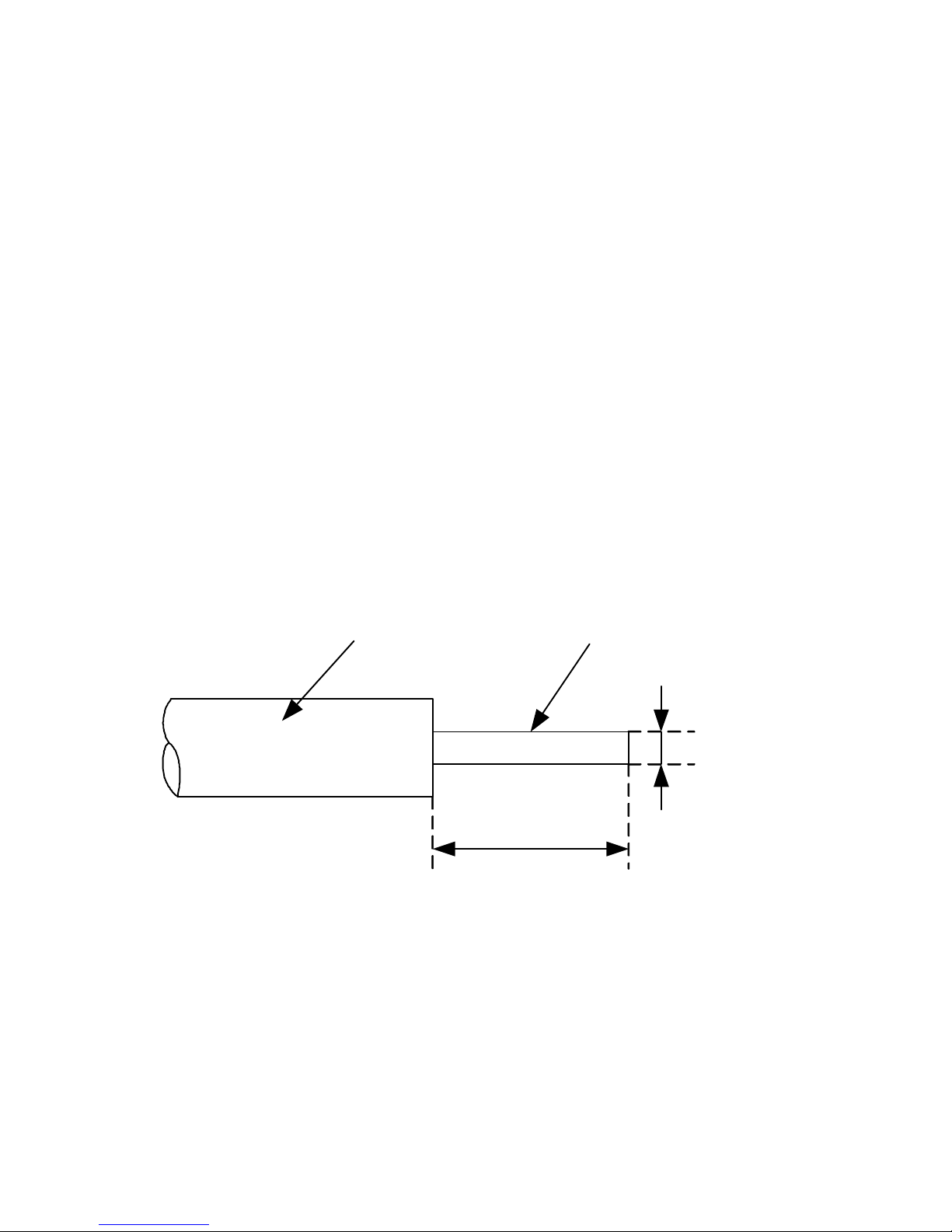
The prepared fiber as figure 2-1, refers to the bare fiber length
after cleaving. The typical value is 1 0 mm ~ 16mm.
10
-
16
mm
F
80
-
125
mm
Coating fiber
Bare fiber
Figure 2-1
2.6
2.6
2.6
2.6 Bare
Bare
Bare
Bare fiber
fiber
fiber
fiber
The Optical Fiber whose coat is removed is called Bare Fiber.
2.7
2.7
2.7
2.7 Picture
Picture
Picture
Picture
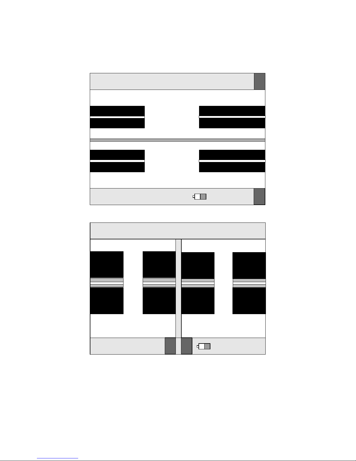
The image of fibers on screen is as figure 2-2 and figure 2-3,
the position of the two fibers is displayed by two image of fiber
Page 10
3
in vertical direction sign ed by ‘ X
’
and ‘ Y ’ . The text on the top
of the screen is the index of used fusion parameter group.
Ready SM
01
2010-02-25 19:33 24
℃
43%RH
X
Y
Figure 2-2
Ready SM
01
2010-02-25 19:33 24
℃
43%RH
X Y
Figure 2-3
2.8
2.8
2.8
2.8 RESET
RESET
RESET
RESET
The operation make s the internal execution parts and circuit
Page 11
4
parameters return to the ir initial stat us . Once reset, the Splicer
is capable of splicing again.
2.
2.
2.
2. 9
9
9
9 Alig
Alig
Alig
Alig n
n
n
n ment
ment
ment
ment
The operation is to adjust the two fibers, so that they are in the
same direction. If the y are not properly aligned, there will be
deviations in the horizontal (x-axis) and vertical (y-axis)
directions, which are called radial offset. The align ment
operation controls the radial offset within the allowable range.
2.
2.
2.
2. 10
10
10
10 Estimated
Estimated
Estimated
Estimated Splice
Splice
Splice
Splice Loss
Loss
Loss
Loss
The splicer calculates the loss at the splicing point according to
the fiber images. The results are reliable when the splic ing is
done correctly.
2.11
2.11
2.11
2.11 Fiber
Fiber
Fiber
Fiber Protection
Protection
Protection
Protection Sleeve
Sleeve
Sleeve
Sleeve
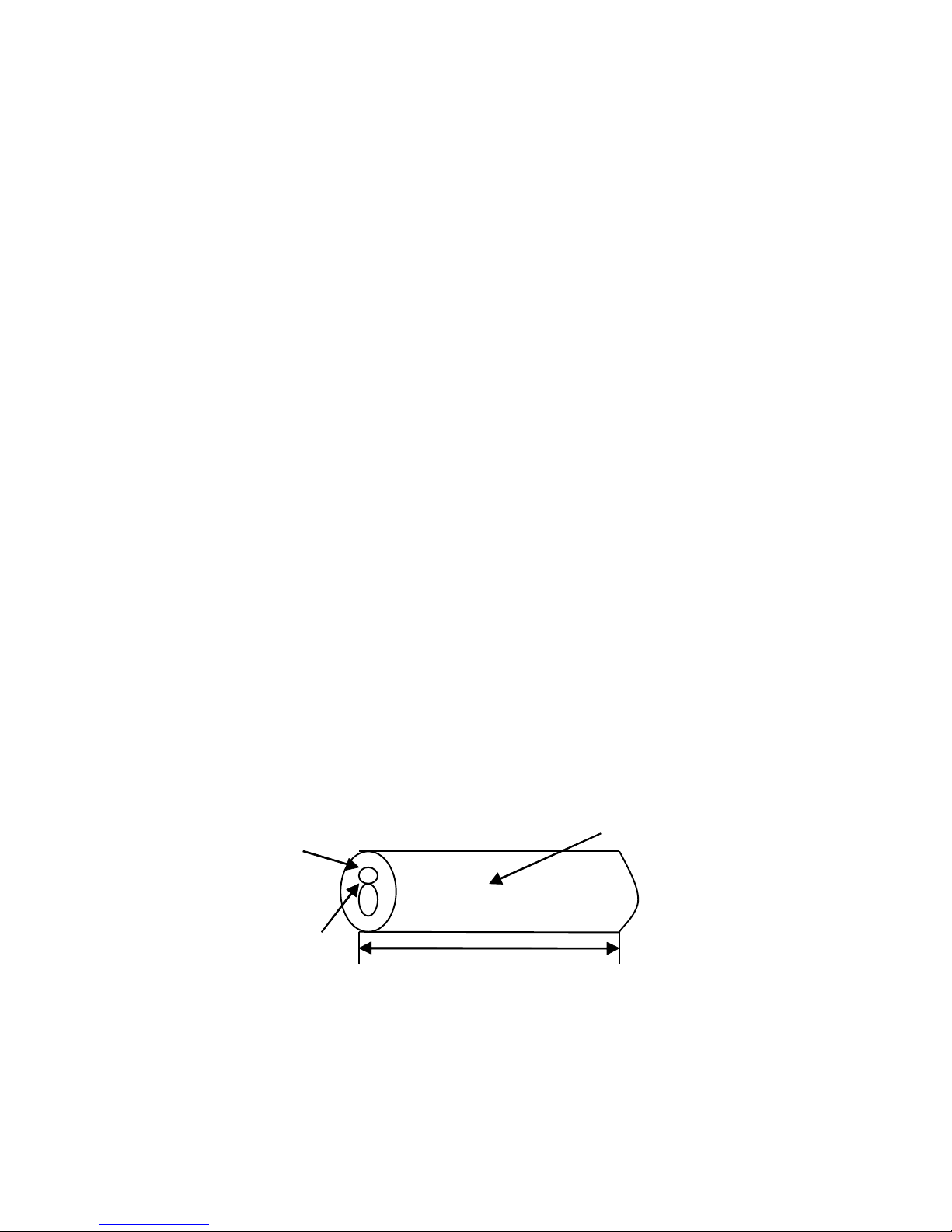
Used to protect the splicing point, as shown in the following
figure.
Figure 2-3
Heat shrink tube
Glass ceramics
Tube of hot melt
60mm
Page 12

5
Chapter
Chapter
Chapter
Chapter 3
3
3
3 Technical
Technical
Technical
Technical Parameters
Parameters
Parameters
Parameters
3.
3.
3.
3. 1
1
1
1 Fiber
Fiber
Fiber
Fiber Requirements
Requirements
Requirements
Requirements
The OFFS can splice the fibers which accord with
ITU-TG . 651 ~ G . 655 , the other quartz fiber on the following
condition can be spliced, but the index can ’ t be assured.
Fiber material: Silica glass
Fiber number: Single
Fiber type: SM, MM, DS, NZDS
Cleave length: 10mm ~ 16mm
Cladding diameter: 80 µ m ~ 150 µ m
Coat diameter: 100 µ m ~ 1000 µ m
3.
3.
3.
3. 2
2
2
2 Fiber
Fiber
Fiber
Fiber Heater
Heater
Heater
Heater
Effective heating length : <60mm
Heating time: 10 ~ 90 s , 9 options available
Typical heating time : 30s
3.
3.
3.
3. 3
3
3
3 Power
Power
Power
Power Supply
Supply
Supply
Supply
DC input: 13.5 ± 0.5
V
, 4.5A. The middle electrical
outlet is anode .
Embedded Li-Ion battery: 11.1V 10.4Ah. C harging
time is about 3.5 hours.
3.
3.
3.
3. 4
4
4
4 Size
Size
Size
Size and
and
and
and Weight
Weight
Weight
Weight
Size : 160mm(L) × 1 40mm(W) × 150mm(H)
Weight : 2.8kg
3.
3.
3.
3. 5
5
5
5 Environmental
Environmental
Environmental
Environmental Conditions
Conditions
Conditions
Conditions
Operating temperature : 0 ° C ~ +40 ° C
Page 13

6
T
emperature limits: -10 ° C ~ +50 ° C
Operating humidity : <95%RH ( no condensing )
Windy speed: <15m/s
Storage temperature : -20 ° C ~ +60 ° C
S torage humidity : no condensing
3.
3.
3.
3. 6
6
6
6 S
S
S
S plice
plice
plice
plice Loss
Loss
Loss
Loss
For those fibers recommended by ITU-T G.651 ~ G.655, the
reference splice loss es are as follows:
SM : 0.0 2 dB
MM : 0.0 1 dB
DSF : 0.04dB
NZDSF : 0.04dB
3.7
3.7
3.7
3.7 The
The
The
The others
others
others
others
Typical fusing time : 8s
Image processing mode: digital
Electrical Pole life-time : 2500 times
Tension test: 2N
5.7 inch TFT colorful LCD
USB port, through which software can be updated and
the splicing data was exported.
VGA port
Real-time display of battery capacity
Embed High light LED, convenience was provided to
night work.
Page 14
7
Chapter
Chapter
Chapter
Chapter 4
4
4
4 Configuration
Configuration
Configuration
Configuration
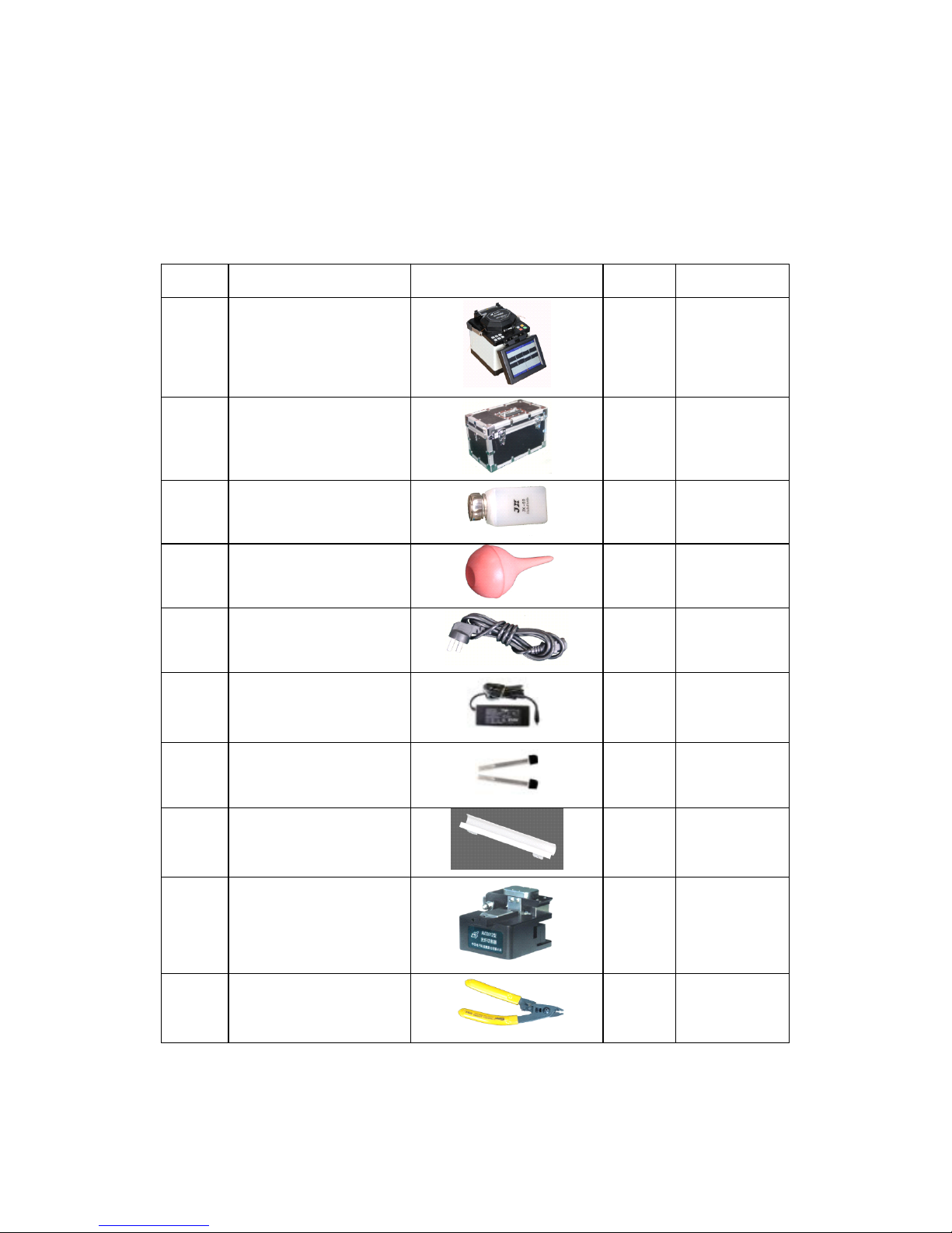
The standard configuration of the OFFS as following table.
Table 4-1
NO Name Picture QTY R emark
1
Optical Fiber
Fusion splicer
1 Host
2 Carrying case 1 Accessory
3 Pump bottle 1 Accessory
4
Blower brush
1 Accessory
5 AC current cable 1 Accessory
6 AC power adapter 1 Accessory
7 Spare electrode s 1 Accessory
8 Cooling tray 1 Accessory
9
AV33012
Fiber Cleaver
1 Optional
10 Miler clamp 1 Optional
Page 15
8
Chapter
Chapter
Chapter
Chapter 5
5
5
5 S
S
S
S tructure
tructure
tructure
tructure and
and
and
and Panel
Panel
Panel
Panel
5.1
5.1
5.1
5.1 Brief
Brief
Brief
Brief introduction
introduction
introduction
introduction of
of
of
of S
S
S
S tructure
tructure
tructure
tructure
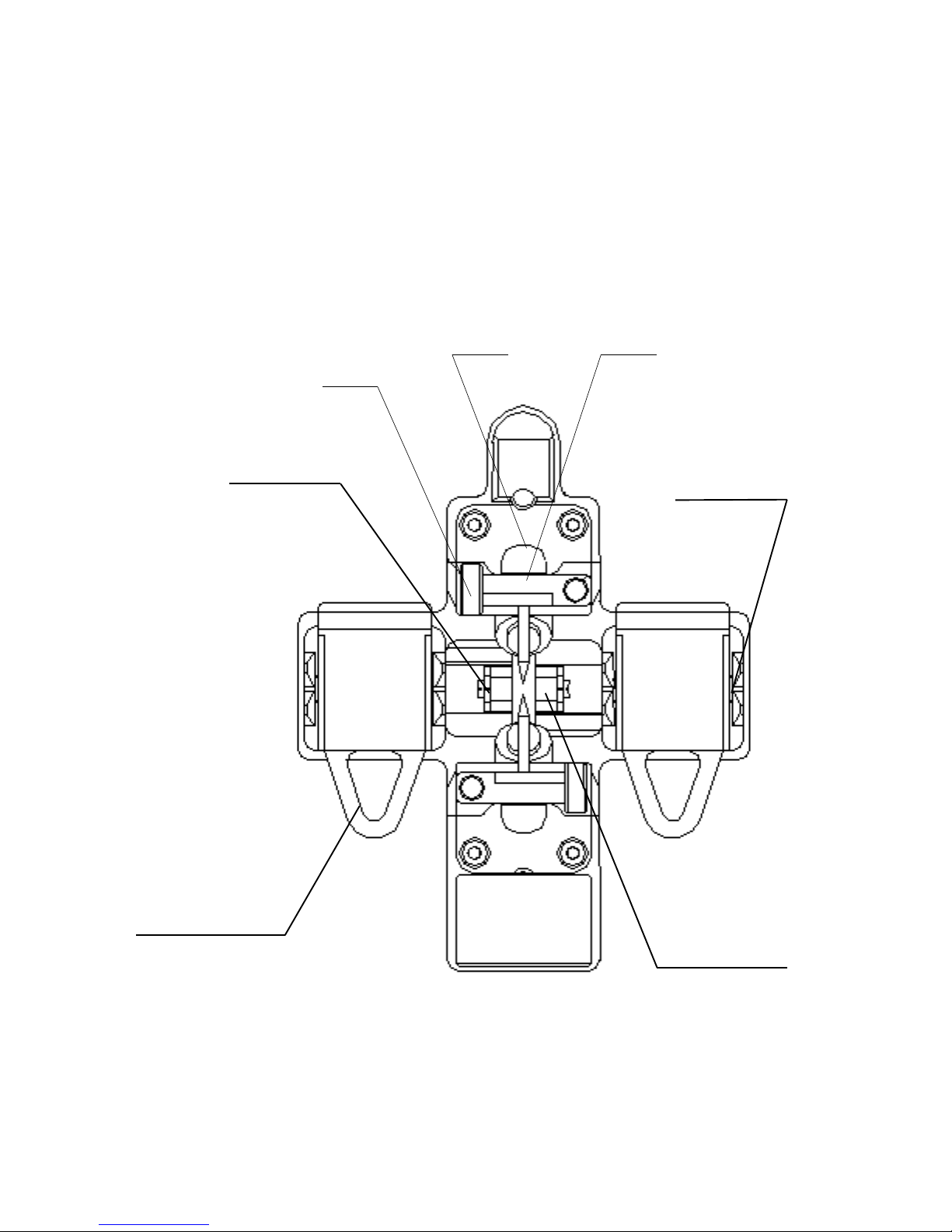
The portable fusion splicer which was specially designed is
suitable for field , lab and other situations. The Jig and Fixture is
as Figure 5-1.
Figure 5-1
Electrode HolderElectrode
Holder
Coating Fiber
Clamp Groove
Cladding Fiber
Holder Clamp Bare Fiber
Clamp Groove
Bare Fiber
Clamp Groove
Page 16

9
5.2
5.2
5.2
5.2 Introduction
Introduction
Introduction
Introduction to
to
to
to Panel
Panel
Panel
Panel
5.
5.
5.
5. 2.1
2.1
2.1
2.1 Shield
Shield
Shield
Shield
The shield is closed unless fibers are going to be put in . Close it
before any key board operation. With a viewfinder mirror and a
holding clamp for bare fiber in the V-groove, it can prevent dust
and wind and provide vertical light for the microscope.
5.2.2
5.2.2
5.2.2
5.2.2 Screen
Screen
Screen
Screen
The viewing angle of the 5.7-inch TFT-LCD can be adjusted.
But please protect its screen from hard sharp things!
5.2.3
5.2.3
5.2.3
5.2.3 Power
Power
Power
Power Supply
Supply
Supply
Supply
To provide convenience for user, the inner Li-Ion battery and
direct current was applied. The direct current was supplied by
the adapter , and the battery was charged when the adapter was
used.
5.2.4
5.2.4
5.2.4
5.2.4 Charging
Charging
Charging
Charging Indicator
Indicator
Indicator
Indicator Light
Light
Light
Light
When the adapter was plugged in, the red indicator LED was
turned on. The green led will shine after charging was
accomplished.
5.3
5.3
5.3
5.3 Introduction
Introduction
Introduction
Introduction to
to
to
to Keyboard
Keyboard
Keyboard
Keyboard
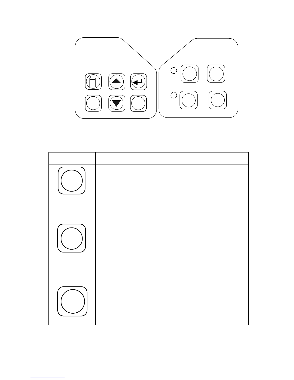
The layout of the keyboard as figure 5-2. There are two kinds
of key operation, i.e. Menu and Fusion.
POWER
,
HEAT
and
RESET
are effective in any mode, the function are listed in table 5-1.
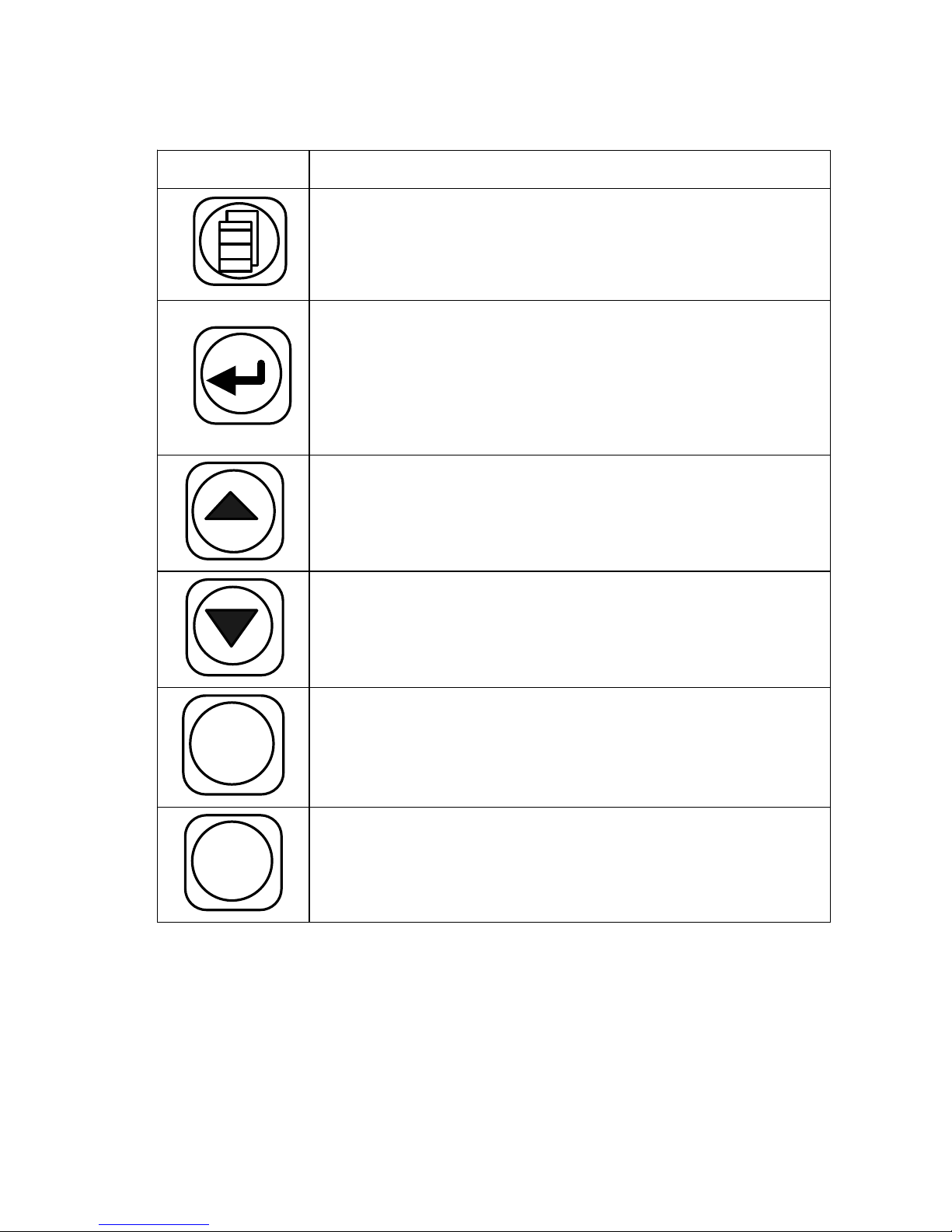
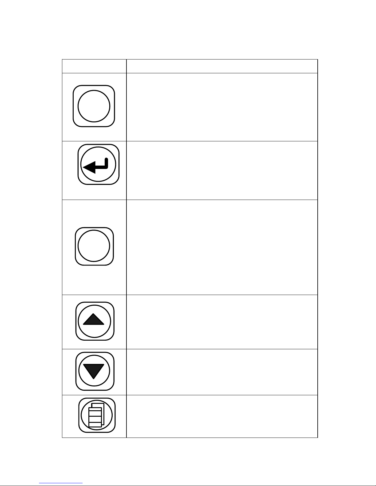
Under Menu and Splice mode, the function of key are listed in
table 5-2, table 5-3.
Page 17
10
X - Y / -
ARC
/+
POWER
RESET
HEAT
AUTO
Figure 5-2
Table 5-1
Key
Function Description
POWER
This key is power, when it was pressed for
about 0.5 second; the instrument would turn on
or turned off.
HEAT
P r ess to operate the reinforcement heater.
The red lamp is lit during operation. And
if
the
cover is covered, the heater will work also . The
heating time can be set in the menu, the
operation refer to APPENDIX B . I f the key is
pressed in the heating procedure, the heater
will stop heating.
RESET
All operations except heating would be
canceled,
if
this key was pressed, and all the
m otional p arts will be move to default position ,
and the instrument is ready for next fusion.
Page 18
11
Table 5-2
Key
Function Description
Exit the current menu and return to the upper
level or to the splicing interface (if in the main
menu currently).
Press to enter the next sub-level menu ; used to
switch between the right and left fibers when
adjusting motor, In the test menu , it confirm s the
start of a test .
Move the cursor up or increase a parameter. In
motor test menu, used to move the fiber up.
Move the cursor down or reduce a parameter. In
moto r test menu, used to move the fiber down.
X - Y / -
If the menu was pressed in menu, the parameter
value would be decreased, or the screen will be
changed.
ARC
/+
If the key was pressed in menu, the parameter
value would be increased.
Page 19
12
Table 5-3
Key Function Description
AUTO
Press this key; the splicer accomplishes
cleaning , gap adjustment, align ment, fusion
splicing and loss estimating functions. The
results will be display ed automatically on the
screen .
Press this key and the splicer will discharge
for a short time between the two electrodes .
Th is operation can get rid of the dust on the
fiber but not of the stabs on the fiber NZDS.
ARC
/+
Press this key and one round of fusion splice
will be done . T he estimated loss will be
displayed on the screen. Do not press this key
without fiber, except for cleaning the
electrodes. During discharge there is thousand
NZDS of voltage between the electrodes. So
for safety, d o n ’ t touch them.
Press this key and the splicer will adjust the
fiber to an appropriate position and clean it
for fusion. When the operation is done, t he
buzzer beeps and the screen display "OK".
Press this key, alignment will be done. When
alignment is done, t he buzzer beeps and the
screen display "OK".
P ress this key to enter the main menu .
Page 20
13
5.4
5.4
5.4
5.4 Introduction
Introduction
Introduction
Introduction to
to
to
to Port
Port
Port
Port board
board
board
board
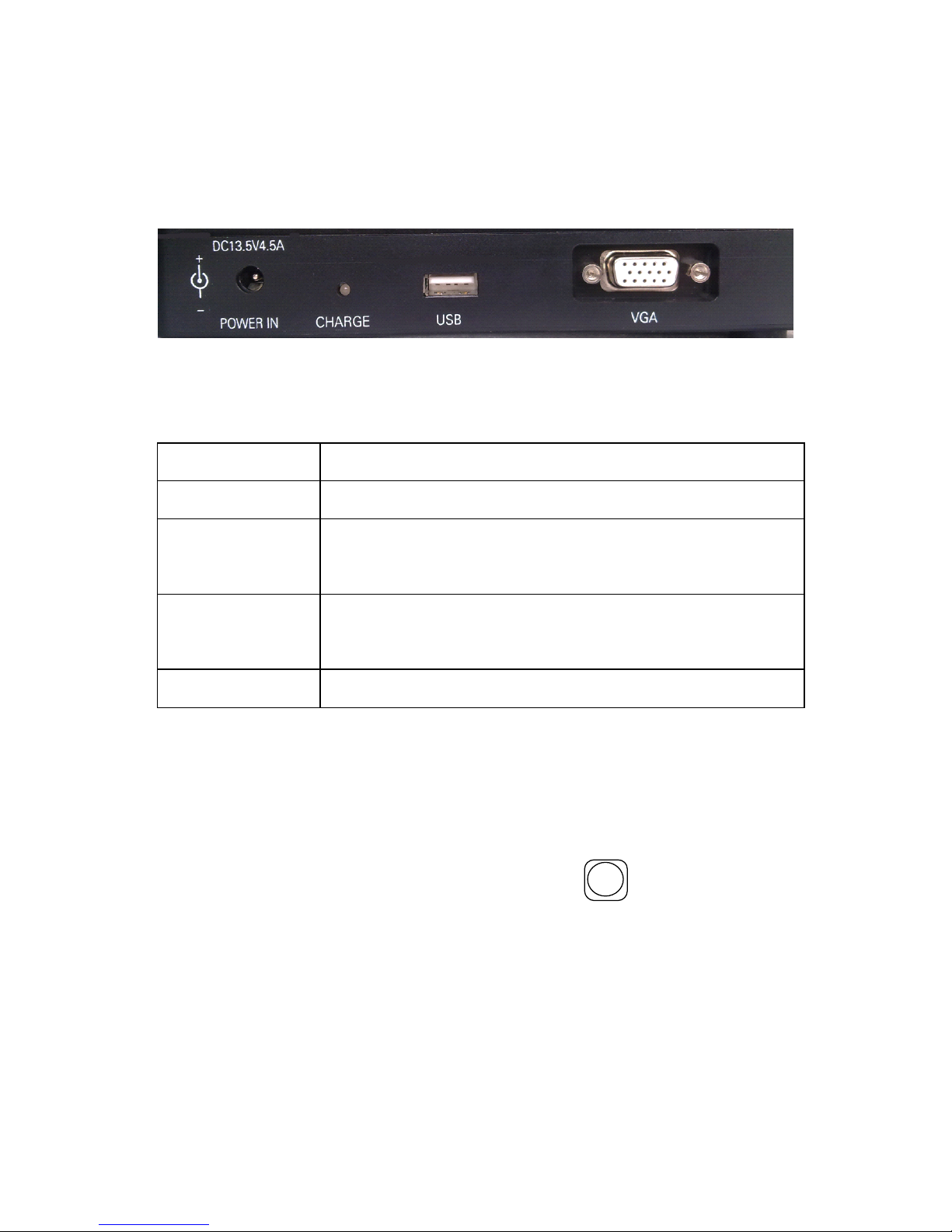
Input/Output port is on the right side of the main body, as figure
5-3 , the function are introduced in table 5-4.
Figure 5-3
Table 5-4
Name
Function Description
POWER IN
DC power input terminal,14.5V,45A.
CHARGE
W hen the lamp is red, the battery is charging .
When the lamp is off, the battery is full.
USB
Used to upgrading software and export ing
record data.
VGA
Video signal output.
5.5
5.5
5.5
5.5 Introduction
Introduction
Introduction
Introduction to
to
to
to Standby
Standby
Standby
Standby Interface
Interface
Interface
Interface
The standby interface and introduction of this OFFS is shown
in figure 2-2. And the standby interface can be switched to the
mode shown in figure 2-3 with the key
X - Y / -
. The image of
fibers, current fusion programme, battery capacity, the inner
temperature, inner humidity, the date and time are displayed on
the screen.
Page 21
14
Chapter
Chapter
Chapter
Chapter 6
6
6
6 Installation
Installation
Installation
Installation and
and
and
and A
A
A
A djustment
djustment
djustment
djustment
a) Open the shield and check whether are there dusty or the
other eye winker ( such as short fiber) in the fixture .
b ) Brush c lean the V-grooves in one direction with a n
alcohol-soaked cotton swab .
c ) Power on the OFFS, and fix the fibers following figure 6-1
and figure 2-2.The cleave length of bare fiber should be
10 mm ~ 16 mm ,and the bare fiber should be put in the V
type groove, Cladding Fiber Holder Clamp hold down the
fiber . The fiber will be seen in the middle of the screen,
don ’ t overlap.
Figure 6-1
d ) Check all the key,
if
there were any exception, please
contact us.
e ) In splice mode , use
ARC
/+
(GAP), (ALIGN) key s to
adjust the fibers to proper positions . If the screen shows
"OK", start splic ing. O therwise notice the follow ing :
Whether the fiber is clean or not? If not, clean it.
Fiber
Bare Fiber
V Type Groove
Coating Fiber
Clamp Groove
Holder Clamp
Page 22

15
Whether the V-groove is clean or not? If not, clean it.
Whether the fiber end profile is good or unqualified
?
If
unqualified, cleave the fiber again.
Whether t he fiber is a standard fiber or not? If not, replace it
with a standard one .
If the trouble is not included in the above lists . Please ask the
manufacturer for help.
f ) Press
AUTO
key , the splicer accomplishes cleaning , gap
adjustment, align ment, fusion splicing and loss estimating
functions. The results will be display ed automatically on
the screen .
Page 23

16
Chapter
Chapter
Chapter
Chapter 7
7
7
7 Basic
Basic
Basic
Basic Operation
Operation
Operation
Operation
7.1
7.1
7.1
7.1 Power
Power
Power
Power Connection
Connection
Connection
Connection
Battery power and DC power were supplied to provide
convenience , and the DC power was connected to the AC
power through an adapter, please make sure the voltage of AC
power is 110V- 240V! When the Fusion was connecting the DC
power, the battery was charged.
7.2
7.2
7.2
7.2 Splicing
Splicing
Splicing
Splicing Parameter
Parameter
Parameter
Parameter Setting
Setting
Setting
Setting
Turn on the power and then the instrument begin self-checking.
If everything was ready, splice mode would be entered, the
display on the screen is as figure 2-2.
7.2.1
7.2.1
7.2.1
7.2.1 Main
Main
Main
Main Menu
Menu
Menu
Menu
Enter
Enter
Enter
Enter The
The
The
The Main
Main
Main
Main Menu
Menu
Menu
Menu
In the splice mode, press the key and the instrument will
enter the menu mode. The screen displays the main menu as
figure 7-1.
Functions
Functions
Functions
Functions in
in
in
in the
the
the
the Main
Main
Main
Main Menu
Menu
Menu
Menu
The s ymbol is a highlight rectangle which can be moved up or
down by or key. Functions in the main menu are as
follows:
“
“
“
“ Fiber
Fiber
Fiber
Fiber Type
Type
Type
Type ”
”
”
” :
:
:
:
To select fiber type.
“
“
“
“ Para.
Para.
Para.
Para. Group
Group
Group
Group ”
”
”
” :
:
:
:
Select the discharge condition group , adjust
the discharge parameters .
“
“
“
“ H
H
H
H eat
eat
eat
eat T
T
T
T ime
ime
ime
ime ”
”
”
”
: Adjust heating time .
Page 24
17
“
“
“
“ Splice
Splice
Splice
Splice mode
mode
mode
mode ”
”
”
” :
:
:
:
Auto, semiauto, manual .
“
“
“
“ Setup
Setup
Setup
Setup ”
”
”
”
: Include CMOS setting, language selection, time
setup, tension test setting, and power save, restore factory
settings.
“
“
“
“
Test
Test
Test
Test
”
”
”
” :
:
:
:
Arc Power , Overlap Test , Bright Setup , M otor
Adjust.
“
“
“
“ M
M
M
M aintenance
aintenance
aintenance
aintenance ”
”
”
” :
:
:
:
Display the splice results or number of
discharges in the memory and clear the pole .
Menu
Para.Group
01
/(
01
-
10
)
Heat Time
30
s
/(
10
-
90
s )
Solice Mode Auto
/
semiAuto
/
Setup
Test
Maintenance
Fiber Type SM
/
MM
/
DS
/
NZDS
SM
Manual
Figure 7-1
Return
Return
Return
Return
In the main menu,
if
the key was pressed , the splice mode
would be return ed to fusion mode.
7.2.2
7.2.2
7.2.2
7.2.2 Enter
Enter
Enter
Enter into
into
into
into the
the
the
the parameter
parameter
parameter
parameter adjustment
adjustment
adjustment
adjustment sub-menu
sub-menu
sub-menu
sub-menu
After the main menu was entered , the fiber type option could be
get by
ARC
/+
or
X - Y / -
.
Page 25
18
The
The
The
The menu
menu
menu
menu as
as
as
as following:
following:
following:
following:
SM:
To save single - mode fiber splic ing parameter groups .
10 groups in total: 0 1 ~ 0 9 which can be changed.
MM:
To save multi- mode fiber splic ing parameter groups .
10 groups in total: 0 1 ~ 0 9 which can be changed.
DS:
To save dispersion shift fiber splic ing parameter groups .
10 groups in total: 0 1 ~ 0 9 which can be changed.
NZDS:
To save nonzero dispersion shift fiber splic ing
parameter groups . 10 groups in total: 0 1 ~ 0 9 which
can be changed.
Para. Group : The current fusion splice parameters group.
7.2.
7.2.
7.2.
7.2. 3
3
3
3 Switch
Switch
Switch
Switch between
between
between
between Splice
Splice
Splice
Splice Parameter
Parameter
Parameter
Parameter Groups
Groups
Groups
Groups
We give an example on how to select the SM1 splice parameter
group to clean the electrodes below .
a ) As the screen in figure 7-1, move the cursor to Fiber type
option with key or key, and select " SM "
with
ARC
/+
or
X - Y / -
.
b ) Move the cursor to "Para. Group" with key or key,
and select " 01 " by press
ARC
/+
key or
X - Y / -
key.
c ) Press to back, and all are OK.
7.2.
7.2.
7.2.
7.2. 4
4
4
4 Adjustment
Adjustment
Adjustment
Adjustment of
of
of
of Splice
Splice
Splice
Splice Parameters
Parameters
Parameters
Parameters
Entering
Entering
Entering
Entering modification
modification
modification
modification menu
menu
menu
menu
If the parameters in SM0 group need to be adjusted, please
select the " Fiber Type " option or " Para. Group " , and press
Page 26
19
to enter menu of a djustment of splice p arameters .
Specification
Specification
Specification
Specification of
of
of
of Splice
Splice
Splice
Splice Parameters
Parameters
Parameters
Parameters
All items in the parameters group as table 7-1.
Parameter Modification :
a) Use the or key to move the cursor to the item
that needs to be adjusted , and then it means this parameter
could be modified.
b) Then adjust the parameter to the ideal value with
ARC
/+
or
X - Y / -
key.
c) The other parameters can be modified in the same way.
Table 7-1
Item Range Unit Default Value
P refuse Time
00 ~ 99
10ms 05
Fuse Time
00 ~ 99
100ms 14
Prefuse Power
00 ~ 99
0.1mA 30
Fuse Power
00 ~ 99
0.1mA 30
Overlap
00 ~ 40
2 µ m 07
End Angle
0.5 ~ 2 .0 1.0 °
2.0
GAP
00 ~ 09
2 µ m 04
Page 27

20
7.3
7.3
7.3
7.3 Adjustment
Adjustment
Adjustment
Adjustment of
of
of
of Splice
Splice
Splice
Splice Power
Power
Power
Power
This part gives instructions on how to achieve low splice loss in
different environment conditions .
a) The recommended parameter group is decided according to
the fiber gap of arc test. The gap length: 015~025.
b) P arameter modification in different circumstance s.
Modify the pre-fusion c u rrent and the fusion c u rrent in the
discharge parameter group, and make the value of arc test meet
the requirements in step b , thus gaining a low loss . The
parameters will reduce at a high temperature and increase at a
low temperature.
7.4
7.4
7.4
7.4 Fiber
Fiber
Fiber
Fiber Operation
Operation
Operation
Operation
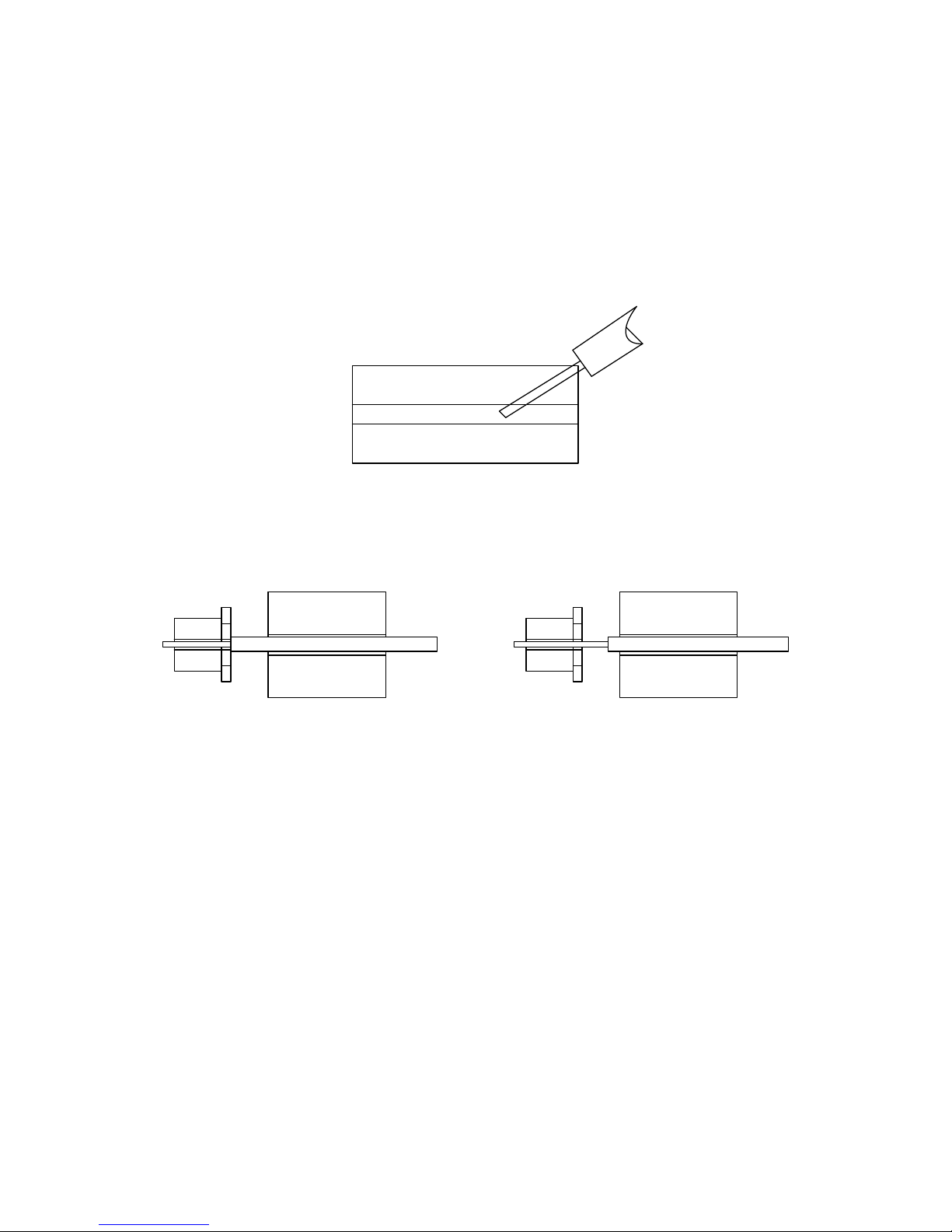
Step 1 : Before splicing, thread the fiber through the optical
fiber protection sleeve.
Step 2 : Remove fiber coating, and then brush the bare fiber
with alcohol-soaked cotton swab. The typical bare
fiber length is 20mm.The concentration of the alcohol
should heavier than 905.
Step 3 : Cut the bare fiber using the cleaver. The typical value
of the cleaver length is 10mm~16mm.
Step 4 : Open the shield and fiber holder clamp carefully. Set
the fiber in the V-groove and the fiber holder on the
holder mount. At the same time, note that the tip of
the bare fiber does not touch anything. Make sure
fiber is at the bottom of the V-groove. If not, reset the
fiber.
Page 28
21
Step 5 : Set the other fiber in the same way. Put the shield
down carefully.
Note:
Note:
Note:
Note:
a) Set the other fiber in the same way. Put the shield down
carefully.
Figure 7-7
Wrong way to install
b) The tip of the coating fiber should keep a distance from the
bare fiber mount.
Right Method
Wrong
Method
Figure 7-8
c ) To be sure the coating fiber was pressed tightly by the hold
clamp . The shield was closed, the fiber should be pressed
on the V-groove by the shield.
7.5
7.5
7.5
7.5 Arc
Arc
Arc
Arc Power
Power
Power
Power
Test
Test
Test
Test
Arc Power Test is very important for obtaining low splice loss.
So before splicing, the test should be done. See the details in
the appendix A.
Fiber
Page 29

22
7.6
7.6
7.6
7.6 Splicing
Splicing
Splicing
Splicing Operation
Operation
Operation
Operation
There are three splicing modes for selection: Manual,
Semi-auto and auto splicing mode.
7.6.1
7.6.1
7.6.1
7.6.1 M
M
M
M anual
anual
anual
anual splicing
splicing
splicing
splicing mode
mode
mode
mode
(1) Strip , clean and cleave the optical fibers.
(2) Open the shield.
(3) Lift the fiber clamps.
(4) Place the optical fibers in the V-grooves.
(5) Carefully close the V-groove clamps. Ensure the bare
fibers are seated at the position between the V-groove and
the electrodes.
(6) Carefully close the fiber clamps and then the shield.
(7) Decide
if
the end face of fibers is good or bad.
( 8 ) Press the key. The fibers move forward to their initial
gap. Do gap adjustment. If either of the two end face
angles is more than the preset value, an error occurs. Press
the
RESET
key and prepare the fiber again.
( 9 ) Press key and "ALIGN" will be displayed on the
screen and the splicer will align the fibers automatically.
The buzzer will beep and the screen will display "OK"
after the operation is done .
( 10 ) Press
ARC
/+
key to end this splicing operation . The result of
estimat ed loss is displayed on the screen .
7.6.2
7.6.2
7.6.2
7.6.2 Semi-auto
Semi-auto
Semi-auto
Semi-auto splicing
splicing
splicing
splicing mode
mode
mode
mode
The difference between s emi-auto and manual splicing mode is
Page 30
23
whether t he splicer automatically puts the two fibers end
profile s to the screen center or not. We advise the user to take
the auto and Semi-auto splicing mode except for special-type
fiber.
E
stimated
Loss
0 .
01
dB
2010-02-26 9:33 24
℃
43%RH
X
Y
Figure 7-7
Tension Passed
2010-02-26 9:33 24
℃
43%RH
X
Y
Figure 7-8
Page 31

24
7.6.3
7.6.3
7.6.3
7.6.3 Auto
Auto
Auto
Auto splicing
splicing
splicing
splicing mode
mode
mode
mode
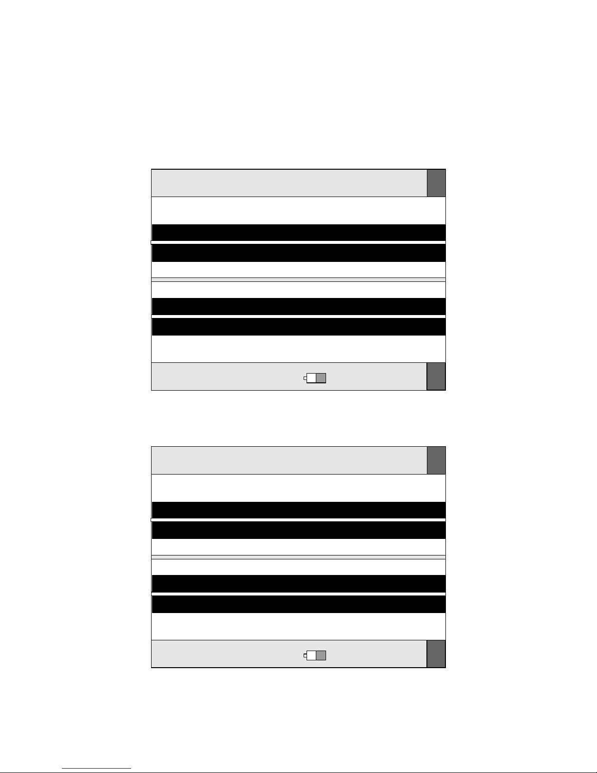
"READY" is displayed on the screen .
(1) Do the same steps as in section 7 . 6.1 : (1) , (2) , (3) , (4) , (5) ,
(6) , (7) .
(2) Close the shield and t he splicer will exercise C lean, G ap,
Align, F usion and Tension Test functions automatically .
T he result will be displayed on the screen as Figure 7-7
and Figure 7-8 .
N otes :
1. Auto splicing mode is convenient, so we advise the user to
take the auto splicing mode.
2. The splicer has the checking function of fiber cutting angle
and fiber end face, when it works in Semi-auto or a uto splicing
mode . The quality of fiber end and face has enormous impact
on the loss of the contacting point; so efforts should be mad as
possible to make the end face plane, and the angle of the place
with the fiber cross-sectional plane should be less than 1◦.
7.7
7.7
7.7
7.7 Estimated
Estimated
Estimated
Estimated Splice
Splice
Splice
Splice Loss
Loss
Loss
Loss
Splice loss could be estimated by observing the splicing
operation and the video of the spliced part. If spliced part is
abnormal (the diameter is bigger or smaller or e t c.), the fiber
should be re-spliced.
Note:
Note:
Note:
Note: When
When
When
When splicing
splicing
splicing
splicing different
different
different
different fibers
fibers
fibers
fibers or
or
or
or multi
multi
multi
multi fiber,
fiber,
fiber,
fiber, a
a
a
a black
black
black
black
line
line
line
line sometimes
sometimes
sometimes
sometimes appears
appears
appears
appears on
on
on
on the
the
the
the spliced
spliced
spliced
spliced part.
part.
part.
part. But
But
But
But it
it
it
it doe
doe
doe
doe s
s
s
s not
not
not
not
affect
affect
affect
affect the
the
the
the splice
splice
splice
splice result.
result.
result.
result.
Page 32
25
7.8
7.8
7.8
7.8 Heater
Heater
Heater
Heater Operation
Operation
Operation
Operation
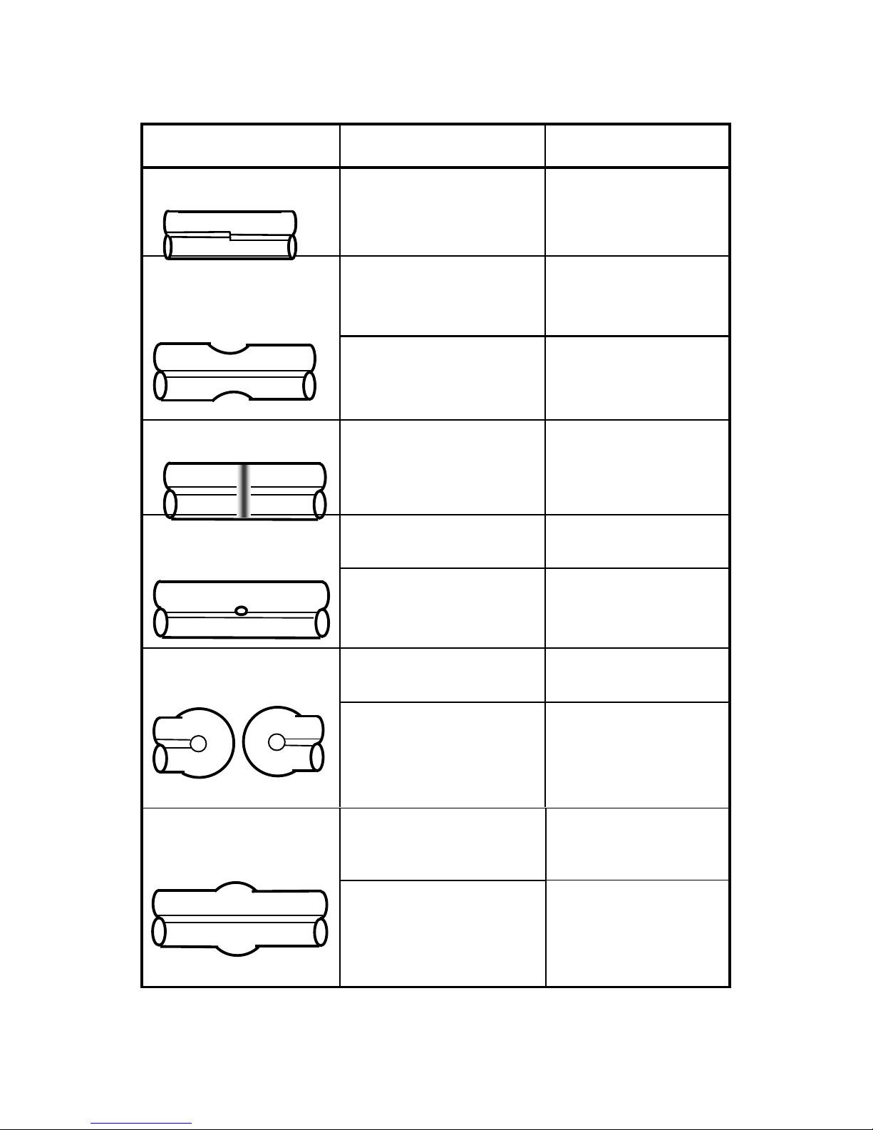
Phenomenon Reason Resolve method
Fiber Not Aligned
Dust in the
V-groove
Clean
V-groove.
Fiber Diameter
Too Small
Discharge power is
inappropriate.
Do Arc Power
test and adjust
the current.
Splice parameter is
inappropriate.
Increase
discharge time or
stuff length.
Black Line
Splice parameter is
inappropriate.
Adjust the
current and the
discharge time.
Gas The fiber end is
unqualified.
Check cleaver.
The current too
small or discharge
time too short.
Adjust the
current and the
discharge time.
Fiber Asunder The stuff length is
too small.
Do an overlap
test.
The current is too
strong
Reduce the
current value and
the discharge
time.
Fiber Diameter
too big
The stuff length is
too big.
Do a overlap test.
The current is too
strong or the
discharge time too
long.
Adjust the current
value and the
discharge time.
Page 33
26
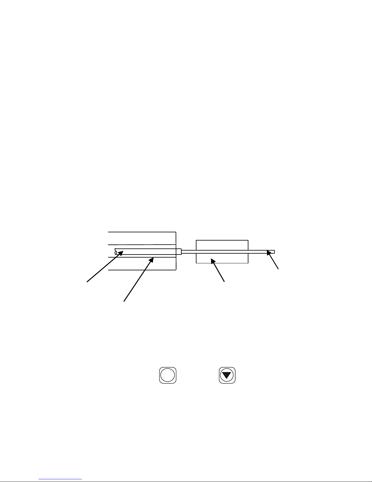
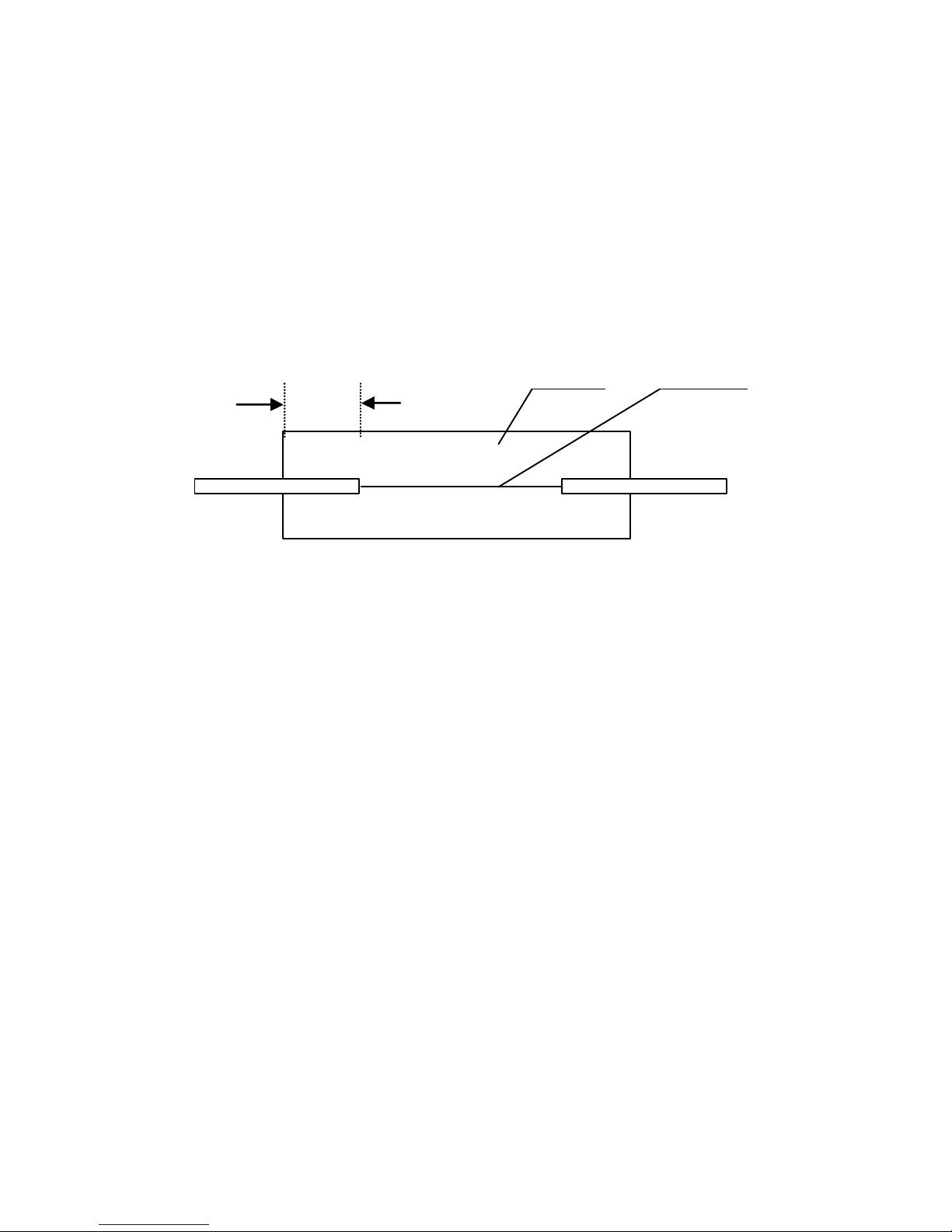
(1) Open the heater cover and the left and right fiber clamps
of heater.
(2) Move the protection sleeve to the center of the splice part.
(3) Hold the fiber, tighten it lightly and then set the splice
point in the center of the heater.
(Do not let the fiber sag)
Figure 7-8
>10mm
Protect Sleeve Bare Fiber
Page 34

27
Chapter
Chapter
Chapter
Chapter 8
8
8
8 Maintenance
Maintenance
Maintenance
Maintenance
8.1
8.1
8.1
8.1 Cleaning
Cleaning
Cleaning
Cleaning
Keep the V-groove, electrode, microscope clean. The shield
should be closed when the splicer is not used.
8.1.1
8.1.1
8.1.1
8.1.1 Cleaning
Cleaning
Cleaning
Cleaning V-groove
V-groove
V-groove
V-groove
If there is dust on the V-groove, the bare fiber alignment
operation may produce a big splice loss. Clean the V-groove in
the following steps.
(1) Open the shield .
(2) Cleave a bare fiber and push the tip of this fiber from the
V-groove’s one end to the other end.
(3) If the above method cannot clean the V-groove, you can
use an alcohol-soaked cotton swab to brush the groove to
get rid of the dust.
8.1.2
8.1.2
8.1.2
8.1.2 Clean
Clean
Clean
Clean ing
ing
ing
ing Electrodes
Electrodes
Electrodes
Electrodes
(1) If the electrodes are polluted because of long-term use ,
wipe the tip of electrodes lightly with a cotton stick dipped
in acetone or a 3 mm wide and 50 mm
l
ong grinding paper.
Pay attention to protecting the electrodes' tip and its
position during cleaning. F inally stabilize electrodes, see
Clear
Clear
Clear
Clear and
and
and
and Stabilize
Stabilize
Stabilize
Stabilize Electrodes
Electrodes
Electrodes
Electrodes
(Section D.4) for detail.
(2) Replacing electrodes is a complex techni cal job , which can
only be done by the manufacturer when the splicer is sent
back for an overhauling.
8.1.3
8.1.3
8.1.3
8.1.3 Cleaning
Cleaning
Cleaning
Cleaning the
the
the
the Objective
Objective
Objective
Objective Lens
Lens
Lens
Lens
The surface of the objective lens must be kept clean. Dust on
Page 35

28
lens can cause trouble in the image process and a big splice
loss.
(1) Turn off the power.
(2) Use a cotton swap soaked with pure alcohol to clean the
lens
’
s surface from center toward rim.
(3) Turn on power. Make sure dust cannot be seen on the LCD
screen.
8.2
8.2
8.2
8.2 Cautions
Cautions
Cautions
Cautions
(1) The splicer is designed for optical telecommunication
fiber s . Don't insert any other type of object in the fiber
clamps or arc center.
(2) Make sure the main body of the splicer is ground ed during
use.
(3) During discharge, the re is a high voltage of several
thousand voltages between the electrodes . So don ’ t touch
them . If there are drops of water on the splice’s main body,
dry it thoroughly before use.
(4) When alcohol drops (including hand grease etc) are
adhere d to the electrodes, accidental discharge might occur.
However, after discharging several times, such liquids will
disappear and normal discharge will proceed.
(5) Do not use the splicer in the environment full of
combustibles (e.g. FREON etc). Otherwise bad splice or
accidents might happen .
(6) Never use any type of solvent other than pure alcohol
when clean ing parts of the machine or fiber s . When
Page 36

29
wip ing the lens with cotton stick (hav ing be en dipped in
alcohol), move it in one direction instead of back and
forth.
(7) Keep the LCD screen away from the sun and high heat
source s .
(8) Turn off the power switch before power cable is
connected.
(9) The period between two consecutive power-on operations
should be longer than 30 seconds.
8.3
8.3
8.3
8.3 Transportation
Transportation
Transportation
Transportation and
and
and
and Storage
Storage
Storage
Storage
(1) Always use the carrying case of the fusion splicer to
prevent moisture , vibration and impact when storing and
transporting the splicer.
(2) Never store the splicer in a place where the humidity or
temperature cannot meet requirements.
Page 37

30
8.4
8.4
8.4
8.4 Alarm
Alarm
Alarm
Alarm indication
indication
indication
indication and
and
and
and abnormal
abnormal
abnormal
abnormal remedy
remedy
remedy
remedy
T
able 8.1
Message Reason and Remedy
OVER RUN
There is dust on the V-groove...
A
fiber is
detached from its V-groove.
A
fiber is dirty.
NO FIBER
The bare fiber is too short... I ncorrect
position.
L/R MOTOR
OVER
A
motor exceeding the limit position,
causing auto reset.
FAILURE
A rc power is too strong or A rc is unstable.
The gap is too big . S tuff length too small or
no stuff at all
BAD
Splice parameters are inappropriate or arc
power is unstable. Dust on fiber end
profiles . The angle of fiber end profile is
too big .
UNSTABLE
ARC
The interval between two fusion is too
short
. Electrodes need clean ing .
NO ARC
Electrodes are dirty. Worn -out electrodes.
Clean or replace electrodes
L/R -END
BAD
Left or right fiber end profile is too bad
;
cleave fiber again.
Page 38
31
APPENDIX
APPENDIX
APPENDIX
APPENDIX A
A
A
A
Test
Test
Test
Test
and
and
and
and Adjustment
Adjustment
Adjustment
Adjustment
A.
A.
A.
A. 1
1
1
1 Entering
Entering
Entering
Entering Sub-menu
Sub-menu
Sub-menu
Sub-menu
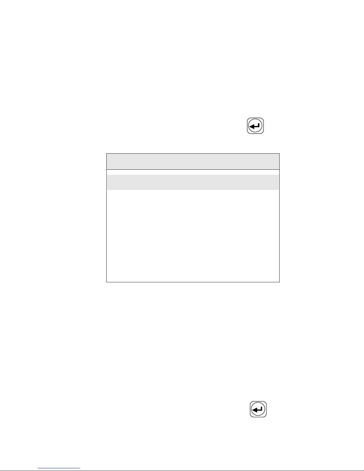
Follow the instruction of section 7.4 , locate two fibers with qualified
end profiles before operation and close the shield.
Select "T est " item in main menu and press the key to display
the test menu on the screen .
Test
Overlap Test
Motor Adjust
Arc Test
Figure A.1
A
A
A
A rc
rc
rc
rc Test:
Test:
Test:
Test: Test the position relationship between the electrodes and
fiber to decide
if
the fiber ends are at the center of the arc. A nd t est
whether the arc power is suitable for fiber splicing or not .
Overlap
Overlap
Overlap
Overlap Test:
Test:
Test:
Test: Test the stuff length of the fiber during fusion splicing.
M
M
M
M otor
otor
otor
otor A
A
A
A djust:
djust:
djust:
djust: Adjust the original location of motor with the bare
fiber clamped on the stage .
A
A
A
A .2
.2
.2
.2 A
A
A
A rc
rc
rc
rc
Test
Test
Test
Test
Select " Arc Test " item in the menu and press the key to confirm.
Page 39
32
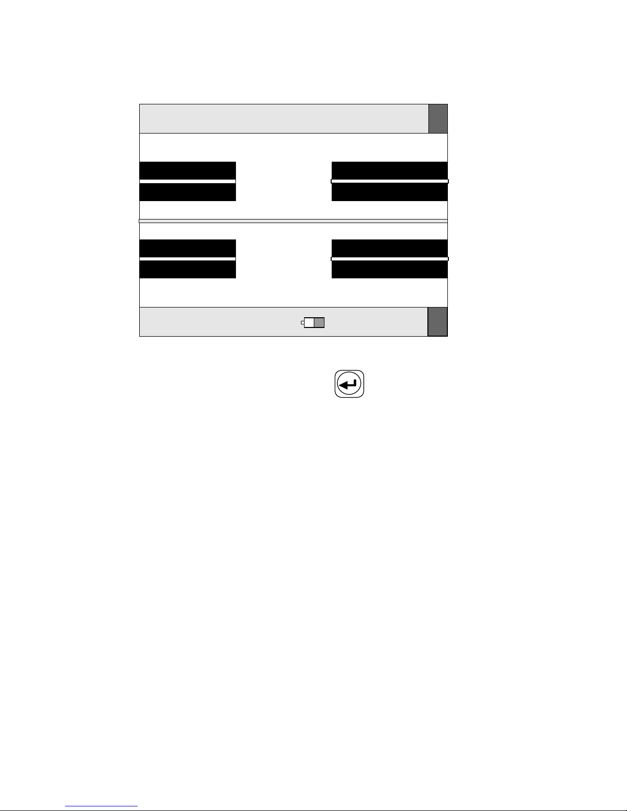
Now the screen displays as Figure A-2.
T Arc Test
2010-02-26 9:35 24
℃
43%RH
X
Y
Figure A-2
Then start the Arc
T
est by pressing the key. The process is as
follows:
a. The splicer puts the two fibers end profile s to the screen
center automatically and accomplishes gap setting and
aligning.
b. An electric al arc is produced by electrodes. Two fiber end
profile s are fused into ball shape.
c. The location of electrodes can be calculated according to the
change of fiber's shape, and displays the following
information .
If the electrode's position is on the left, the screen displays " Gap
XXX
T
o R XX X ".
If the electrode's position is to the right, the screen displays " Gap
XXX
T
o
L
XX X ".
Page 40
33
If the electrode's deviation is within 1 0, no adjustment is needed. The
electrodes location adjustment requires high skill. It should be done
by a technician. If the value of "GAP" is between 15 and 25, the arc
power is suitable for fiber splicing . I f the value of “ GAP ” is less than
this range , please increase " Prefuse Power " and " Fuse Power " ,
contrarily , decrease " Prefuse Power " and " Fuse Power " . Press
the key to return to the former operation after the test is done .
Before the Arc Power test, the electrodes should be cleaned. The test
is effective only after the arc becomes stable.
A
A
A
A .3
.3
.3
.3 Overlap
Overlap
Overlap
Overlap
Test
Test
Test
Test
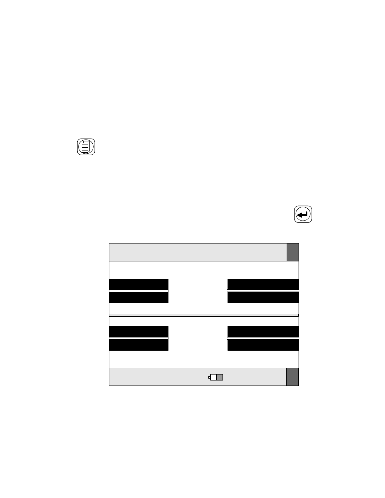
Choose the " Overlap Test " item in test menu and press key to
confirm. Now the screen displays as Figure A-3.
T Overlap Test
2010-02-26 9:35 24
℃
43
%
RH
X
Y
Figure A-3
a. Send the two end profile s of fibers to the center of the screen
automatically, and accomplish gap setting.
b. The left fiber exits from the screen, but the right fiber goes
Page 41

34
forward by "Stuff" value.
c. The amount of stuff is calculated and displayed .
The stuff length of the fiber is set by the customer according to the
arc power, fiber type and material. When it needs to be changed,
follow the adjustment method of discharge parameters. Press the
key to return after the test is done.
A.4
A.4
A.4
A.4 Adjustment
Adjustment
Adjustment
Adjustment of
of
of
of Motor
Motor
Motor
Motor
Fiber Fusion Splicer has a function to check the initial position s of
the left and right motor automatically . If the location is wrong during
self-test, the splicer will switch to motor adjustment mode
automatically. Only after the location of motor is adjusted can the
splicer do fusion splic ing . Otherwise, when the position of coated
fiber clamp is found straying from the center obviously, i.e. it is
short er or long er when the fiber stripping length should be 1 6 mm.
We can enter into the motor adjustment through the menu to adjust
the original location of the left and right motor. The operation
processes under these two conditions are as follows:
Use
Use
Use
Use the
the
the
the Menu
Menu
Menu
Menu to
to
to
to Adjust
Adjust
Adjust
Adjust
a. Locate the 1 6 mm stripping length fiber properly and close
the shield.
b. Enter the test sub-menu, choose the "M otor A djust " item and
press the key . T he splicer will enter motor adjustment
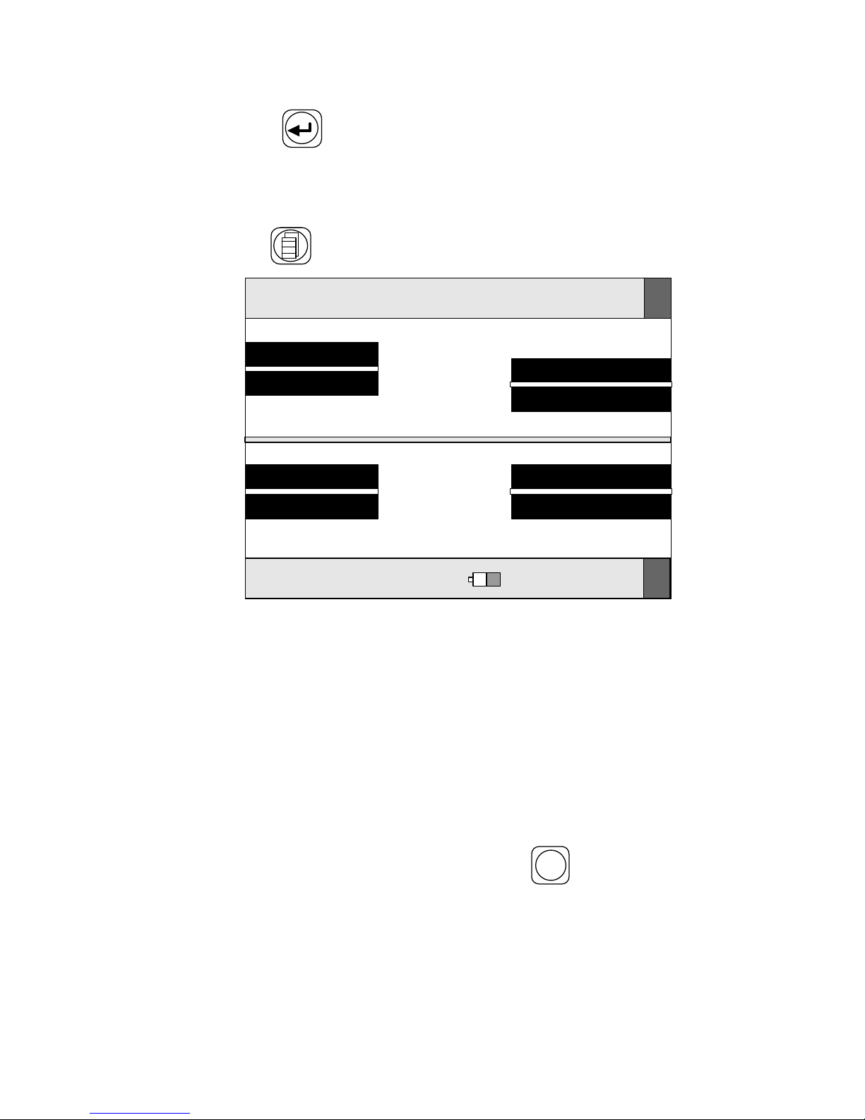
status. The screen displays as shown in Fig A-4 .
c. Use the , and key to adjust motor's location
until the fiber is displayed on the screen.
Page 42
35
d. Press key so that the buzzer beeps to indicate the new
location of the motor is accepted automatic ally by the
splicer. Th is way the adjustment is done .
e. Press key to return.
T Left Motor
2010-02-26 9:35 24
℃
43
%
RH
X
Y
Figure A-4
Note:
Note:
Note:
Note:
If the left and right motors are close to the V-grooves, the two 16 mm
stripping-length fibers may collide or one of them occupies the whole
screen. In this case , the fibers could be located after the splicer enters
the motor-adjustment status. The motors can be adjusted one after
another.
If the ground ing condition is good and the
RESET
key is pressed before
the instrument is turned off, the position of motors will need no
adjustment for quite a long time.
Page 43
36
APPENDIX
APPENDIX
APPENDIX
APPENDIX B
B
B
B H
H
H
H eat
eat
eat
eat Time
Time
Time
Time Adjustment
Adjustment
Adjustment
Adjustment
B
B
B
B .1
.1
.1
.1 Functions
Functions
Functions
Functions
The splicer has 9 types of heat time for customers to select. Heat time
can be set by menu. When a heat-shrink sleeve needs heat ing , press
the
HEAT
key and the heat oven will turn on/off (the indication light
on/off) automatically for a length of set time. When the light is on,
the
HEAT
key is void. There are no influences on other functions
when the heater is in work.
B
B
B
B .2
.2
.2
.2 Adjustment
Adjustment
Adjustment
Adjustment
Select the "H eat T ime " item in main menu and press the key to
confirm . Use the
X - Y / -
or
ARC
/+
key to re-select the heat time. Press
the key to return to the former menu; or press the
RESET
key to
return to the "READY" status. The set-time will not be lost even
if
the power turns off.
Page 44
37
APPENDIX
APPENDIX
APPENDIX
APPENDIX C
C
C
C Setup
Setup
Setup
Setup
The function of
“
Setup ” include s COMS sensor , L anguage , Data and
Time, Tension, Power Save and Restore Factory Settings. Select
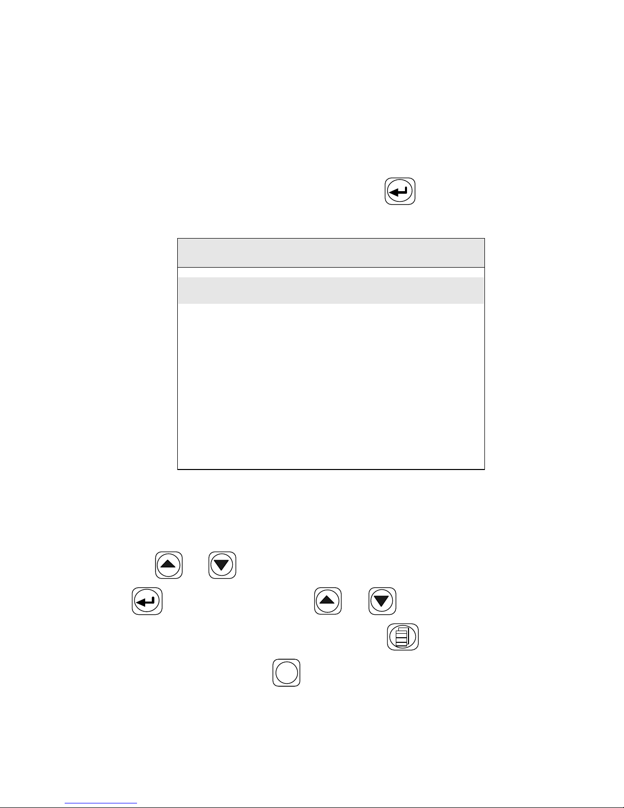
" Setup " item in main menu and press the key to confirm. The
screen displays as shown in Figure C-1.
Setup
Language
Date and Time
Tension
:
OFF
Power Save
:
OFF
Restored Factory Settings
COMS Sensor
Figure C-1
C.1
C.1
C.1
C.1 Language
Language
Language
Language
Use the or key to move the cursor to “ Language ” , and press
the key to enter. Use the or key to move the cursor
to the item which you want, and press the key to return to the
former menu; or press the
RESET
key to return to the "READY" status.
Page 45
38
C.2
C.2
C.2
C.2 Date
Date
Date
Date and
and
and
and Time
Time
Time
Time
Use the or key to move the cursor to
“
T ime Setting ” , and
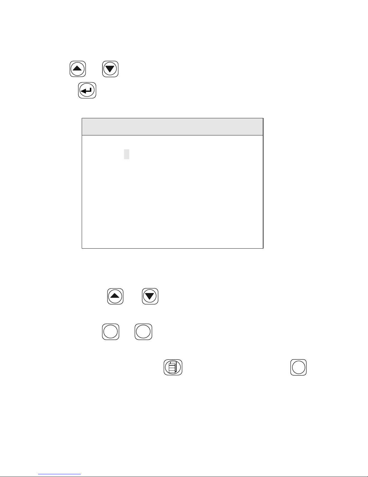
press the key to enter , t he screen displays as shown in Figure
C-2
Date and Time
20 0
–
02
–
26
11
:
41
:
43
1
Year Month Date
Hour Min Sec
Figure C-2
Set time in the following steps:
1. Use the or key to move the cursor to the item
which you want to change,
2. Use the
X - Y / -
or
ARC
/+
key to modify the number
3. After the date and time are calibrated, new time will be
remembered. Press the key to return. or press the
RESET
key to return to the "READY" status.
Page 46

39
C.3
C.3
C.3
C.3 Tension
Tension
Tension
Tension
If the function of “ Tension ” is set to “ ON ” , a proof- test ( about 2N) of
the Splice point is performed automatically upon completion of
fusion splicing. Set the function of “ Tension ” in the following steps:
1. Use the or key to move the cursor to “ Tension ” ,
2. Use the
X - Y / -
or
ARC
/+
key to switch between different mode.
C.4
C.4
C.4
C.4 Power
Power
Power
Power Save
Save
Save
Save
T he splicer will be shut down certain duration of time (about 5
minute s) to save unnecessary loss of battery capacity, when it is set to
power saving mode. Use the or key to move the cursor to
“ Power Save ” , and then u se the
X - Y / -
or
ARC
/+
key to switch between
different mode.
C.5
C.5
C.5
C.5 Restore
Restore
Restore
Restore Factory
Factory
Factory
Factory Settings
Settings
Settings
Settings
W hen the instrument is produced, there are some parameter s( such as
Fiber Type, Para. Group, Heat Time and Fusion Mode) installed 。
R estoring factory settings is set by pressing the key twice,
when the cursor is move d to “ Restore Factory Settings ” . W hen the
instrument is restored factory settings, the parameter s of F iber Type is
SM, P ara . Group is 01, the Heat Time is 50s, the Fusion Mode is
Manual, the Tension is set to “ OFF ” , the Power Saving is ON. The
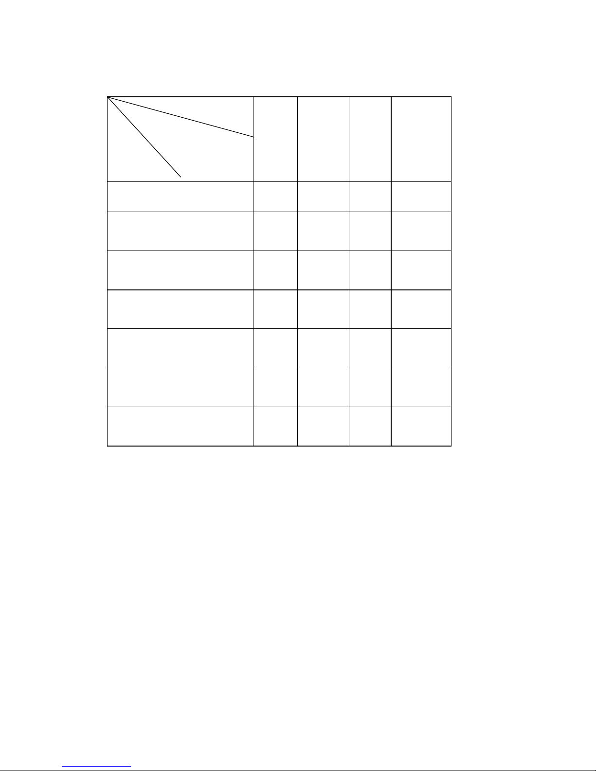
table C-1 below show s other default parameter s.
Page 47
40
Table C-1
F iber Type
V
alue
parameter
SM MM DS NZDS
Prefuse Time 08 22 08 08
Fuse Time 14 18 14 14
Prefuse Power 30 30 30 30
Fuse Power 30 30 30 30
Overlap 07 08 09 10
End Angle 2.0 2.0 2.0 2.0
Gap 04 04 04 04
Page 48
41
APPENDIX
APPENDIX
APPENDIX
APPENDIX D
D
D
D Maintenance
Maintenance
Maintenance
Maintenance
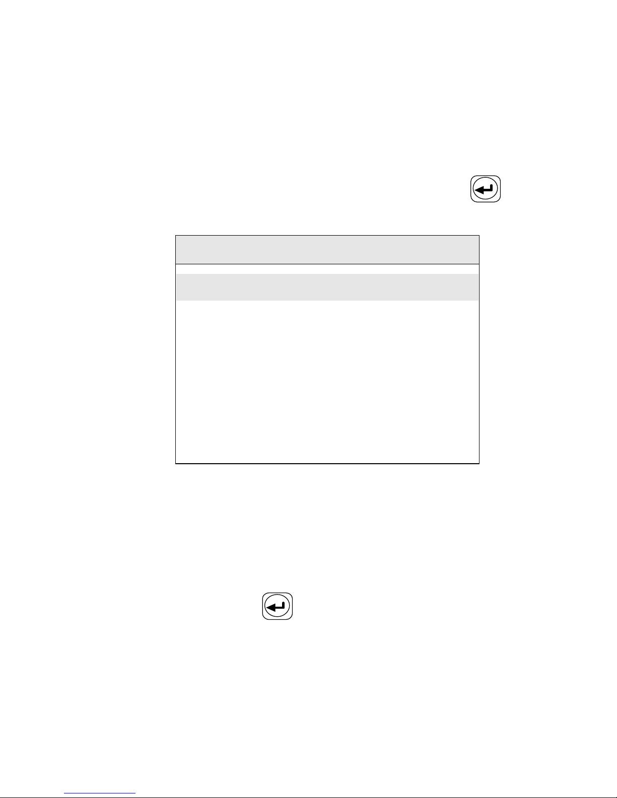
The function of Maintenance include s Fusion Record, Export
Records, Arc Count, and Clear Electrodes and stabilize Electrodes.
Select "Maintenance" item in main menu and press the key to
confirm. The screen displays as shown in Figure D-1.
Maintenance
Fusion Record
00015
Export Record
Arc Count
00020
Clear Electrode
Stablize
Electrode
Fig D-1
D.1
D.1
D.1
D.1 Fusion
Fusion
Fusion
Fusion Record
Record
Record
Record
The memory of the splicer can store 5 00 0 groups of fusion splice
results and discharge times. The failed and bad fusion splice results
are abandoned automatically. Select the
“
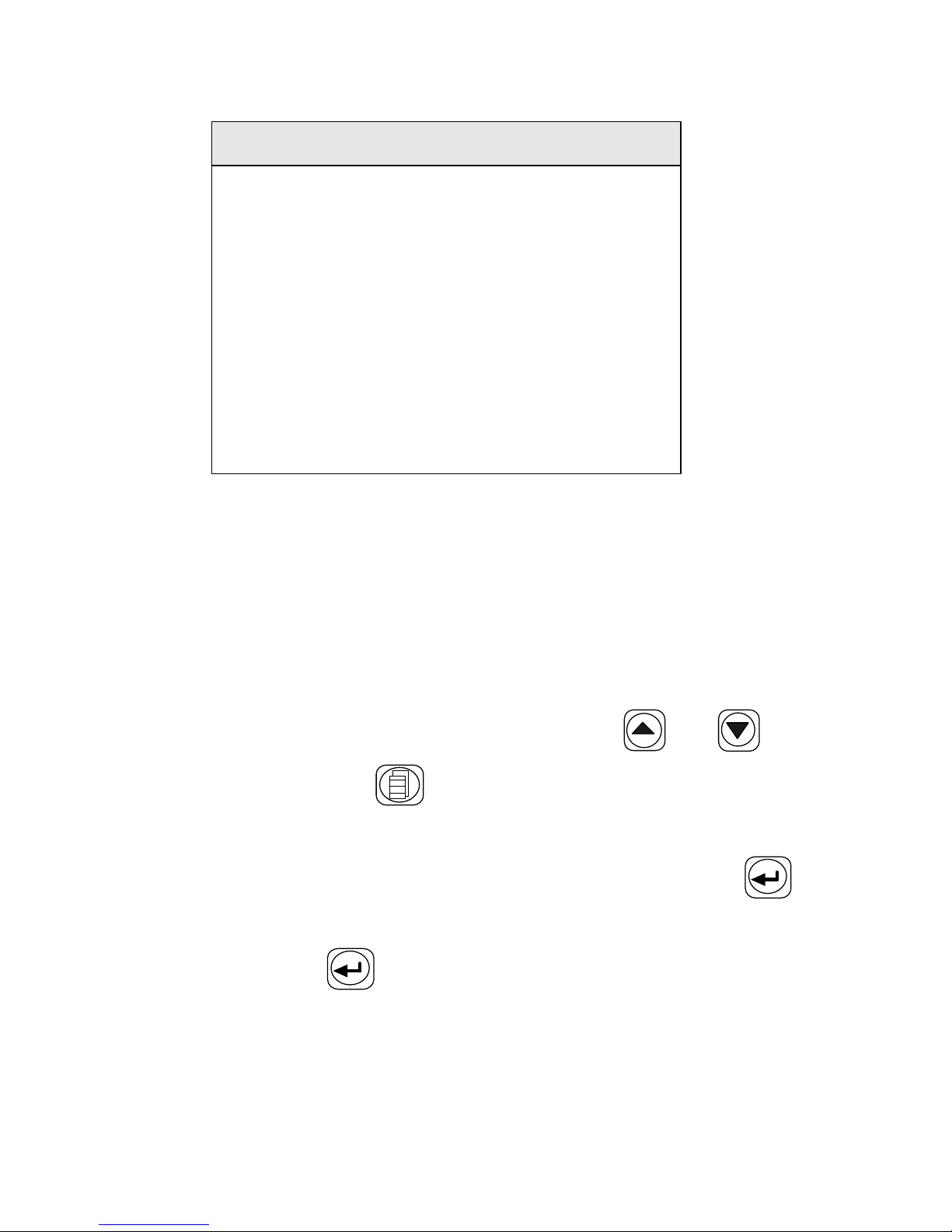
Fusion Record " item in the
sub-menu and press the key to confirm. The splicer displays as
Figure D-2.
Page 49
42
Record NO
.
00012
SM
01
Pretime
:
05
Fustime
:
14
Prearc
:
30
Fustime
:
30
Overlap
:
07
Angle
:
1
. 0 / 0 . 7
Gap
:
04
Loss
:
0
.
01
dB
2010
-
02
-
28 14
:
25
Figure D-2
This memory can store 5 0 0 0 groups of fusion splice results; the No.
(Number) is 00 00 ~ 4 99 9 , store d in turn. When the 5 00 0 groups are
full , the new data will cover the old ones in turn. The record time
refers to the end time of each splice. The displayed sequence number
is convenient for customers to inquire after any information . You can
change the sequence number in turn by pressing the or to
check all the data. Press the key to return to the former menu.
D
D
D
D .
.
.
. 2
2
2
2 Export
Export
Export
Export Record
Record
Record
Record
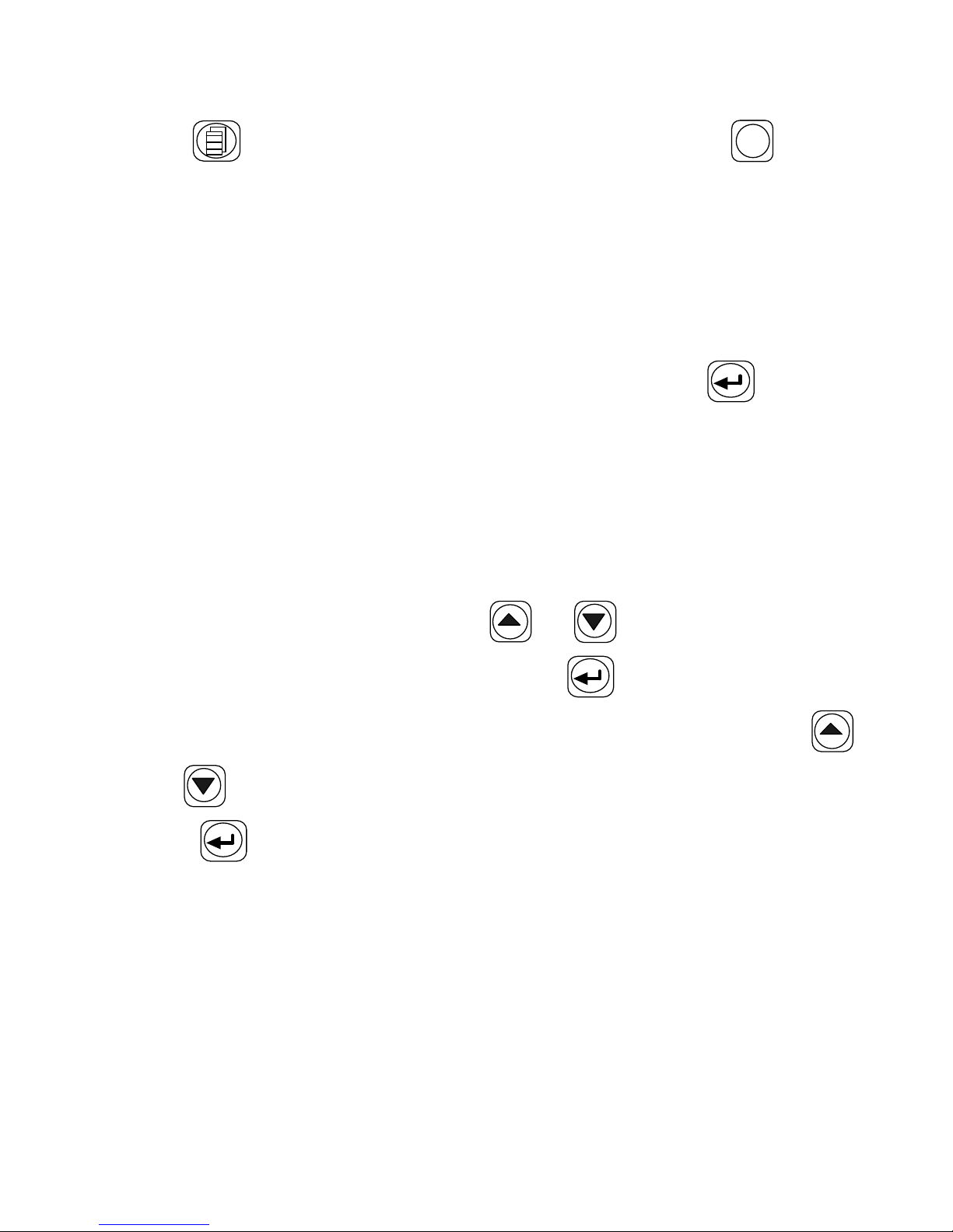
Select the " Export Record " item in the sub-menu and press the
key to confirm , the “ Please Insert U disk ” message is displayed on
the screen. P ress the key to confirm again, the data will be
exported to U disk. When the data is exported, t he “ Please pull out U
disk ” message is displayed on the screen. Pull out U disk, and p ress
Page 50
43
the key to return to the former menu , or press the
RESET
key to
return to the "READY" status.
Notes:
Notes:
Notes:
Notes: The
The
The
The format
format
format
format of
of
of
of U
U
U
U disk
disk
disk
disk must
must
must
must be
be
be
be
FAT!
FAT!
FAT!
FAT!
D
D
D
D .3
.3
.3
.3 Arc
Arc
Arc
Arc Count
Count
Count
Count
The counter can count up to 999999. Every fusion will be taken into
account , no matter the fusion splice is successful or not. Select
"Maintenance" item in main menu and press the key to
confirm. The Arc Count is displayed in sub-menu .
D.4
D.4
D.4
D.4 Clear
Clear
Clear
Clear and
and
and
and Stabilize
Stabilize
Stabilize
Stabilize Electrodes
Electrodes
Electrodes
Electrodes
Electrodes wear with use and also must be cleaned periodically due
to silica oxide buildup. It is recommended that the electrodes should
be replace 2500 arc discharges . When the electrodes are replaced, it is
necessary to stabilize it. Use the or key to move the cursor
to ” Clear Electrodes ” , and press the key to confirm , the
Electrodes will be cleaned later. I n the same way , Use the
or key to move the cursor to “ Stabilize Electrodes ” , and press
the key to confirm , the electrodes will be stabilized .
Page 51

44
APPENDIX
APPENDIX
APPENDIX
APPENDIX E
E
E
E The
The
The
The Parameters
Parameters
Parameters
Parameters of
of
of
of MMF
MMF
MMF
MMF A
A
A
A djust
djust
djust
djust
Enter the parameter adjust menu, select multi-mode fiber parameter.
The screen displays as shown in Table.E-1.The parameters in the
Table. E-1 can be as the reference.
Table. E -1
Parameters
Values
Prefuse Time 25
Fuse Time 18
Prefuse Power 22
Fuse Power 22
Overlap 07
E nd Angle 2.0
Gap 06
1. When s plic ing multi-mode fiber, gas sometimes appears on the
spliced part. Increase the ‘
Prefuse Time
’
and reduce “
Prefuse Power
” ,
“ Fuse Power ” .
2. If the line on the spliced part break off, increase the ‘
Fuse Time
’ ,
“ Prefuse Power ” , “ Fuse Power ” .
3. If the spliced part fiber diameter too small, reduce “ Prefuse
Power ” , “ Fuse Power ” .
4. The “ Fuse Power ” and
“
Prefuse Power
” must keep the same.
Note:
Note:
Note:
Note: When
When
When
When splicing
splicing
splicing
splicing multi
multi
multi
multi fiber,
fiber,
fiber,
fiber, a
a
a
a white
white
white
white or
or
or
or black
black
black
black line
line
line
line sometimes
sometimes
sometimes
sometimes
appears
appears
appears
appears on
on
on
on the
the
the
the spliced
spliced
spliced
spliced part.
part.
part.
part. But
But
But
But it
it
it
it doe
doe
doe
doe s
s
s
s not
not
not
not affect
affect
affect
affect the
the
the
the splice
splice
splice
splice result.
result.
result.
result.
Page 52
45
APPENDIX
APPENDIX
APPENDIX
APPENDIX F
F
F
F Exchange
Exchange
Exchange
Exchange of
of
of
of Electrodes
Electrodes
Electrodes
Electrodes
1. Turn power off and unplug power cord.
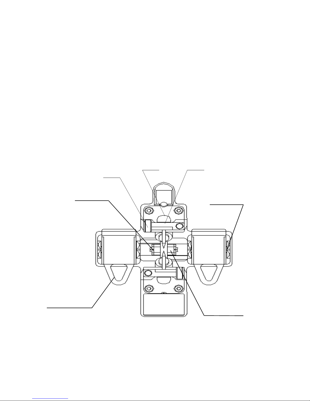
2. Open the shield . The FigureF-1 shows the structure of the
electrodes.
3. Removed electrode by loosing screw of the electrode holder.
Insert new pair of electrodes and tighten screw alternately
while pushing insulated part of the electrode.
4. Plug in the power cord, turn on the power switch, and then
stabilize electrodes.
Figure F-1
Electrode
Holder
Electrode
Holder
Coating Fiber
Clamp Groove
Cladding Fiber
Holder Clamp
Bare Fiber
Clamp Groove
Bare Fiber
Clamp Groove
Page 53

46
APPENDIX
APPENDIX
APPENDIX
APPENDIX G
G
G
G System
System
System
System Update
Update
Update
Update
1. Press the
AUTO
key, simultaneously ,
Press the
POWER
key, and
then th
e splicer return to the " Update st atus , the screen
displays as shown in Figure G-1.
System Update
Please Insert U Disk
Figure G-1
2. Insert U disk with update file, the system of the splicer is
update automatically . After update, the
“
Up update Finished.
Please pull out U disk and restart. “ Message is displayed. I f
the format of U disk which is inserted the splicer is not
FAT,
the “ Initialize failed disk not find. ” message is displayed on
the screen
;
I f the format of U disk without update file is
FAT,
the “ Update failed. Check U disk or Update file. ”
message is displayed on the screen .
W hen the system of the splicer is upgraded, please restart it.
Notes:
Notes:
Notes:
Notes:
(1) The format of U disk must be
FAT,
others
cannot be
identi fied.
(2) Keep the splicer on and do not pull out U disk
in the
process of upgrade .
(3) Power up the splicer again whether
update
is successful or
not.
Page 54

47
APPENDIX
APPENDIX
APPENDIX
APPENDIX H
H
H
H F
F
F
F iber
iber
iber
iber Cleaver
Cleaver
Cleaver
Cleaver
H.1
H.1
H.1
H.1 General
General
General
General
The cleav er is a tool used for cleaving multiple and single stand
optical fibers. Fiber requirements and specifications are as
shown in Table H. 1.
Table H. 1 Specifications
H.2
H.2
H.2
H.2 Operation(Refer
Operation(Refer
Operation(Refer
Operation(Refer to
to
to
to Figure
Figure
Figure
Figure H-
H-
H-
H- 1)
1)
1)
1)
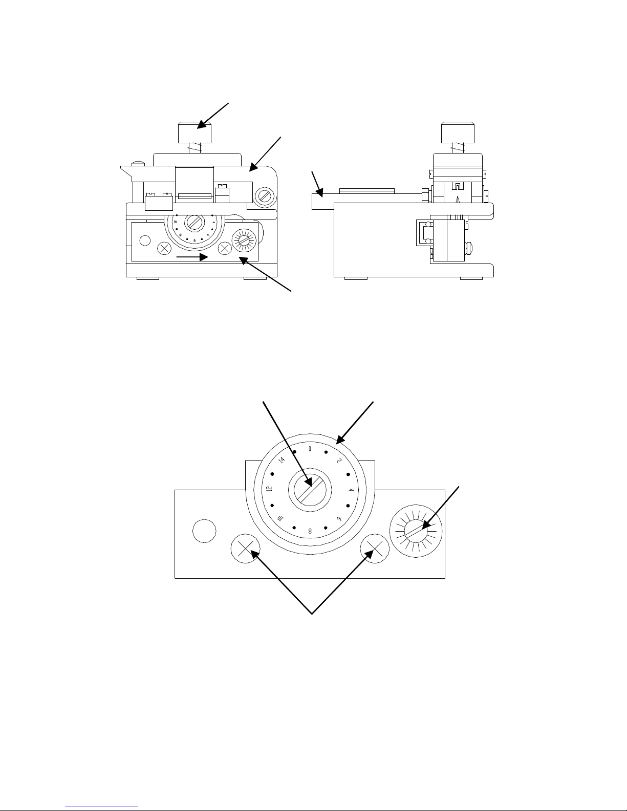
1. Open the bare fiber clamp .
2. Ensure the blade carrier is positioned towards the operator
side .
3. Set the fiber holder into the fiber holder groove .
4. Ensure the fibers do not cross one another .
5. Close the bare fiber clamp .
6. Slide the blade carrier to score the fiber(s) .
7. Press the cleaving button to cleave the fiber(s) .
8. Open the bare fiber clamp .
9. Remove the fiber holder and dispose of the scrap ends .
Fiber type :
Single fiber , 250 & 900 µ m coating
Clad diameter :
80-125 µ m
Cleave length :
10mm
Dime ns ion s :
70W × 57D × 61H , mm
Weight :
300 grams
Typical cleave angle :
1 °
Blade life :
20,000 fiber cleaving
Page 55
48
Cleaving button
Bare fiber clamp
Fiber holder groove
Blade carrier
Figure H- 1
H.3
H.3
H.3
H.3 Maintenance(Refer
Maintenance(Refer
Maintenance(Refer
Maintenance(Refer to
to
to
to Figure
Figure
Figure
Figure H-
H-
H-
H- 2)
2)
2)
2)
Blade fixing screw Blade
Blade height
adjustment screw
Blade height locking screw
Figure H- 2
If cleaving conditions become poor try the following steps.
1. Clean the upper and lower rubber surfaces of the bare fiber
clamp and blade edge using a cotton swab moistened with
Page 56
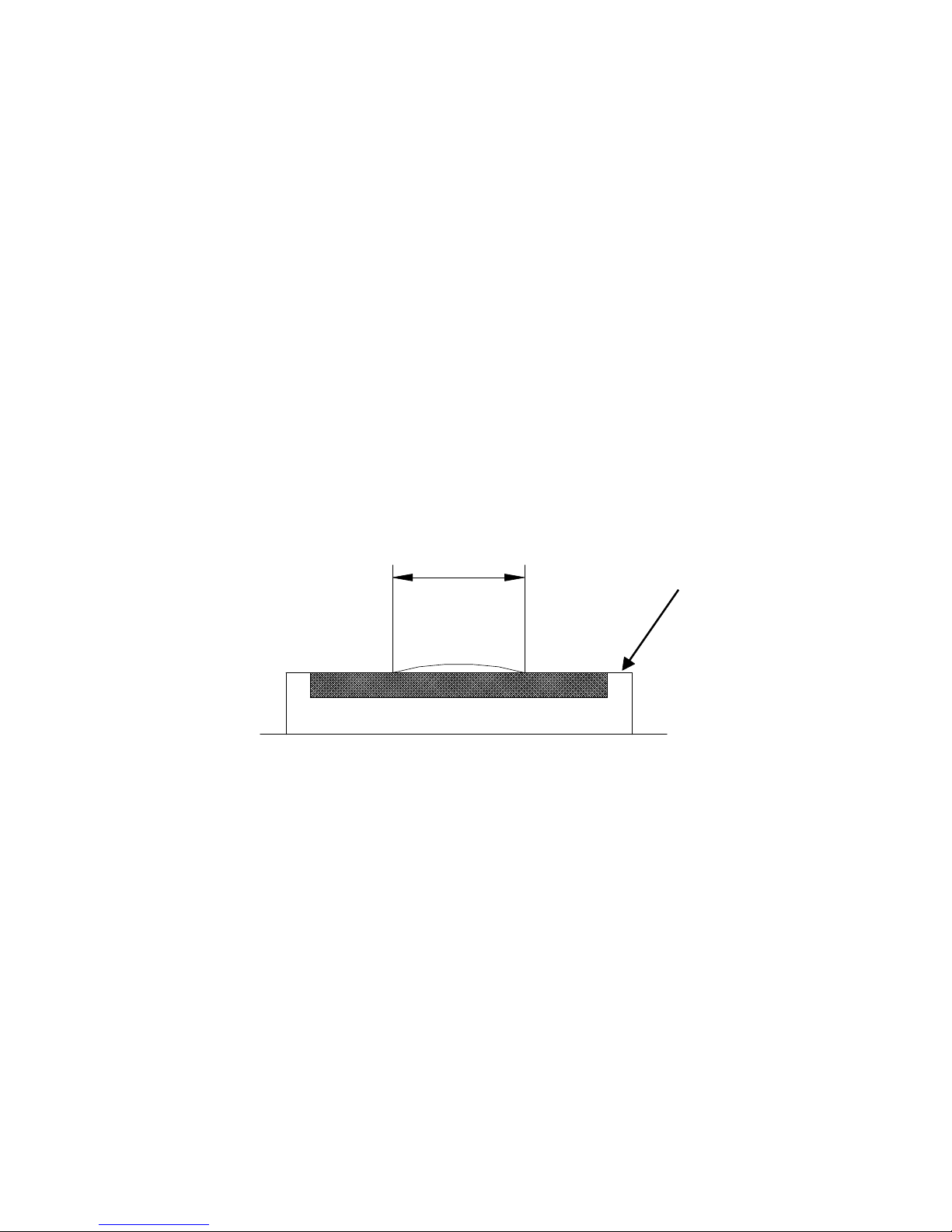
49
pure alcohol .
2. Rotate the blade position .
Loosen the fixing screw
Turn the blade to the next position as numbered
Tighten the blade fixing screw
Adjusting
Adjusting
Adjusting
Adjusting the
the
the
the blade
blade
blade
blade height
height
height
height
After all 16 blade positions have been used, the blade can then
be raised to allow for additional cleaves. This height adjustment
can be done twice providing a total of 48 usable blade positions.
To raise the blade height .
3mm
Bare fiber clamp
Figure H- 3
Loosen the blade height locking screws.
Referring to Figure H- 3, turn the blade height
adjustment screw so that the length of exposed blade
edge along the bare fiber clamp is 4 to 5mm .
Tighten the blade height locking screws.
Blade
Blade
Blade
Blade replacement
replacement
replacement
replacement
Remove the blade fixing screw and used blade
Set new blade and tighten blade fixing screw
Page 57

50
--
--
--
-- Contact
Contact
Contact
Contact us:
us:
us:
us:
Nanjing OrienTek Optical Communication Limited
Add: RedSun Building, North Bridge Road
Nanjing, Jiangsu, China
 Loading...