

Page 1
HM-60358
OPERATING MANUAL
Low-Speed Synchronous Motor
SMK
Series
Introduction
Before use
Only qualied personnel of electrical and mechanical engineering should
work with the product.
Use the product correctly after thoroughly reading the section “Safety
precautions.” In addition, be sure to observe the contents described in
warning, caution, and note in this manual.
The product described in this manual has been designed and manufactured
to be incorporated in general industrial equipment. Do not use for any other
purpose. Oriental Motor Co., Ltd. is not responsible for any damage caused
through failure to observe this warning.
Safety precautions
The precautions described below are intended to prevent danger or injury
to the user and other personnel through safe, correct use of the product.
Use the product only after carefully reading and fully understanding these
instructions.
Description of signs
Handling the product without observing the instructions
that accompany a "Warning" symbol may result in serious
injury or death.
Handling the product without observing the instructions
that accompany a “Caution” symbol may result in injury
or property damage.
The items under this heading contain important handling
instructions that the user should observe to ensure the
safe use of the product.
Description of graphic symbols
Indicates "prohibited" actions that must not be performed.
Indicates "compulsory" actions that must be performed.
yDo not use the motor in explosive or corrosive environments, in
the presence of ammable gases, locations subjected to splashing
water, or near combustibles. This may cause re or injury.
yDo not forcibly bend, pull or pinch the motor lead wires or cable.
Doing so may result in re.
yDo not disassemble or modify the motor. This may cause injury.
yBe sure to insulate the connection terminals of the capacitor and
external resistor. Failure to do so may result in electric shock.
yDo not touch the connection terminals of the motor or capacitor
immediately (within 30 seconds) after the power is turned o. The
residual voltage may cause electric shock.
yAssign qualied personnel the task of installing, wiring, operating/
controlling, inspecting and troubleshooting the motor. Failure to
do so my result in re or injury.
Thank you for purchasing an Oriental Motor product. This Operating Manual
describes product handling procedures and safety precautions.
yPlease read it thoroughly to ensure safe operation.
yAlways keep the manual where it is readily available.
yTurn o the power in the event of a power failure. Or the motor
may suddenly start when the power is restored and may cause
injury or damage to equipment.
yTake measures to keep the moving parts in position for vertical
operations such as elevator applications. Failure to do so may result
in injury or damage to equipment.
yInstall the motor in an enclosure. Failure to do so may result in
injury.
yConnect the motor securely in accordance with the connection
example. Failure to do so may result in re.
yFor a power supply for DC excitation, use a DC power supply with
reinforced insulation on its primary and secondary sides. Failure to
do so may result in electric shock.
yDo not use the motor beyond its specications. This may cause
injury or damage to equipment.
yDo not touch the motor and external resistor during operation or
immediately after stopping. This may cause a skin burn(s).
yDo not carry the motor by holding the motor output shaft, motor
lead wires or cable. Doing so may cause injury.
yDo not use the motor near ammable objects. Doing so may result
in re or a skin burn(s).
yDo not leave anything around the motor that would obstruct
ventilation. Doing so may result in damage to equipment.
yDo not touch the rotating part (output shaft) during operation.
Doing so may cause injury.
yProvide a cover over the rotating parts (output shaft) of the motor.
Failure to do so may result in injury.
yProvide an emergency stop device or emergency stop circuit
external to the equipment so that the entire equipment will
operate safely in the event of a system failure or malfunction.
Failure to do so may result in injury.
yImmediately when trouble has occurred, stop running and turn o
the driver power. Failure to do so may result in re or injury.
yThe motor surface temperature may exceed 70 °C
(158 °F) even under normal operating conditions.
If the operator is allowed to approach the running
motor, attach a warning label as shown below in a
conspicuous position. Failure to do so may result in
skin burn(s).
Warning label
Precautions for use
•Do not give any constraint to the motor shaft.
If the motor shaft is constrained with a load torque exceeding the motor
torque, the motor cannot be started and a vibrating condition will occur,
resulting in a signicant decrease in motor life. Be sure to use a load torque
that is less than the motor torque.
•Grease leakage
On rare occasions, a small amount of grease may ooze out from the geared
motor. If there is concern over possible environmental damage resulting from
the leakage of grease, check for grease stains during regular inspections.
Alternatively, install an oil pan or other device to prevent leakage from
causing further damage. Oil leakage may lead to problems in the customer's
equipment or products.
1
Page 2
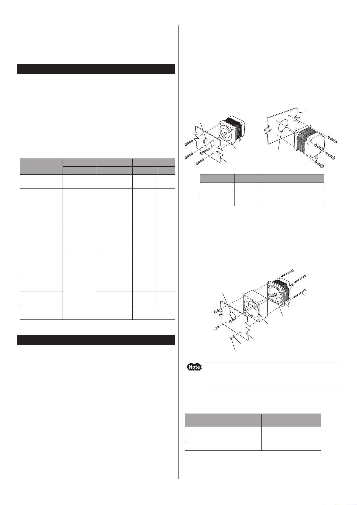
•Allowable torque
Pilot holder
Mounting plate
apped holes
P
(counterbore or
through hole)
rews
Hexagonal nuts
Boss holder
(counterbore or
through hole)
Operate the motor by making sure the sum of the acceleration/deceleration
torque at the starting/stopping of the motor and the load (friction) torque
doesn’t exceed the allowable torque. Operating the motor in excess of the
allowable torque may result in a damaged gear part.
Preparation
Checking the product
Verify that the items listed below are included. Report any missing or
damaged items to the branch or sales oce from which you purchased the
product.
yMotor ...................................... 1 unit
yMounting screw .................. 4 pcs. (Included with geared motor)
yCapacitor ................................ 1 pc.
yCapacitor cap ....................... 1 pc. *
yExternal resistor ................... 1 pc. (Included with the
yOPERATING MANUAL ........ 1 copy (this document)
* Included with the capacitor that has UL in the model name.
Motor model
SMK014K-A
SMK014K-B
SMK014A-A
SMK014A-B
SMK014MA-A
SMK014MA-B
SMK0A-A *
SMK0A-B
SMK237A-A
SMK237A-B
SMK216A-GN
SMK216A-GNB
SMK5100A-A
SMK5100A-B
SMK5160A-A
SMK5160A-B
SMK5100C-A
SMK5100C-B
SMK550A-GN
SMK550A-GNB
SMK550C-GN
SMK550C-GNB
* The box () in the model name indicates a number representing the gear ratio.
*
CH06BFAUL
CH06BUL
Capacitor External resistor
Model Capacitance (μF) Ω W
CH120
CH12UL
CH25UL
CH035B
12 − −
0.6 − −
1.2 − −
2.5 400 30
0.6 1500 30
0.6 400 30
0.35 2000 30
SMK5
types)
Installation method
Install the motor onto an appropriate at metal plate having excellent
vibration resistance and heat conductivity. When installing the motor, secure
it with screws so that there is no gap between the motor and metal plate.
zRound shaft type
Using the four mounting holes (or tapped holes) located on the motor
mounting surface, secure the motor with four screws (not included).
Fit the pilot located on the motor mounting surface into a pilot-receiving hole
having performed counterbore or through-hole machining.
type
SMK0
•
(counterbore or
through hole)
T
Motor type Screw size Tightening torque [N•m (oz-in)]
type M3 1 (142)
SMK0
type M4 2 (280)
SMK2
type M5 3 (420)
SMK5
zPinion shaft type
Assemble a gearhead with a motor. Match the pilot sections of the gearhead
and motor, and assemble them while slowly turning the gearhead clockwise/
counterclockwise.
And secure with the screw set included with the gearhead using four
mounting holes on the motor frame.
Fit the boss section on the gearhead mounting surface into a boss-receiving
hole having performed counterbore or through-hole machining.
Gearhead (sold
separately)
SMK2, SMK5
•
ilot holder
Motor
Pinion shaft
Boss
type
Mounting plate
Sc
Pilot
Installation
Location for installation
The motor has been designed and manufactured to be incorporated in
equipment. Install it in a well-ventilated location that provides easy access for
inspection. The location must also satisfy the following conditions:
2
yInside an enclosure that is installed indoors (provide vent holes)
yOperating ambient temperature −10 to +40 °C (+14 to +104 °F)
(non-freezing)
yOperating ambient humidity 85% or less (non-condensing)
yArea that is free of explosive atmosphere or toxic gas (such as sulfuric gas)
or liquid
yArea not exposed to direct sun
yArea free of excessive amount of dust, iron particles or the like
yArea not subject to splashing water (rain, water droplets), oil (oil droplets)
or other liquids
yArea free of excessive salt
yArea not subject to continuous vibration or excessive shocks
yArea free of excessive electromagnetic noise (from welders, power
machinery, etc.)
yArea free of radioactive materials, magnetic elds or vacuum
y1000 m (3300 ft.) or lower above sea level
Mounting plate
Washers
Do not assemble the motor and gearhead forcibly, nor bring the pinion
shaft into forcible contact with the gearhead’s side plate or gear. This
precaution must be observed in order to avoid abnormal noise or
reduced service life in the gearhead.
Combinations of motors and gearheads (sold separately)
Use the pinion shaft type in combination with the following gearhead:
Motor model
SMK216A-GN, SMK216A-GNB 2GNK, 2GNS
SMK550A-GN, SMK550A-GNB
SMK550C-GN, SMK550C-GNB
* The box () in the model name indicates a number representing the gear ratio.
Applicable gearhead model
(sold separately) *
5GNK, 5GNS
Page 3

zGeared motor (SMK0A type)
Cross-recessed head machine screw
with spring washer (included)
• Type with mounting leg • Type with mounting bracket
Mounting bracket
(ø0.18 in.)
Lead wires
Capacitor cap
Capacitor cap
N
CCWCW
Capacitor
CCWCW
N
Capacitor
CCWCW
Capacitor External resistor
N
Mount the motor with four screws (included) through the four tapped holes
provided on the motor mounting surface.
yScrew size: M3
yTightening torque: 1 N•m (142 oz-in)
Pilot holder
Connection
Installing the capacitor cap
If a capacitor cap is included with a capacitor, connect lead wires to the
capacitor terminals before covering with the capacitor cap.
Mounting plate
Installing the capacitor
Secure the capacitor in place using screws (not included), as shown in the
gure.
Tightening torque: 1 N•m (142 oz-in) or less
Capacitor
M4 screw
Capacitor
ø4.3 mm
(ø0.17 in.)
Mounting leg
M4 screws
5×ø4.5 mm
Installing a load
When installing a load to the motor, align the centers of the motor output
shaft and load shaft.
When installing a exible coupling or pulley on the motor output shaft, do so
without damaging the output shaft and bearings.
Permissible radial load and permissible axial load
The radial load and axial load on the motor output shaft must be kept under
the permissible values in the table.
Permissible radial load [N (lb.)]
Motor type
SMK014A
SMK014K
SMK014M
SMK0A
SMK237
SMK5100
SMK5160
* This table indicates the permissible radial load and permissible axial load of the
gearhead.
Distance from the tip of output shaft [mm (in.)]
0 (0) 5 (0.2) 10 (0.39) 15 (0.59) 20 (0.79)
20 (4.5) 25 (5.6) 34 (7.6) 52 (11.7) − 10 (2.2)
10 (2.2)
*
54 (12.1)
260 (58) 290 (65) 340 (76) 390 (87) 480 (108) 60 (13.5)
15 (3.3) 20 (4.5) 30 (6.7) − 15 (3.3)
67 (15) 89 (20) 130 (29) − 20 (4.5)
Permissible
axial load
[N (lb.)]
Connection and operation
yBe sure to connect the included capacitor as shown in the gures.
An external resistor is also included in the
ySetting the switch to the CW side rotates the motor output shaft in the
clockwise direction. Setting the switch to the CCW side rotates the motor
output shaft in the counterclockwise direction. The rotation direction of the
motor output shaft indicates as viewed from the output shaft side.
yIf the power supply is turned o, the motor stops.
yThe output shaft of the pinion motors with ratios of 25, 30 and 36
rotate in the opposite direction of the motor shaft.
yThe output shaft of the geared motors with ratios of 15, 18,
rotate in the opposite direction of the motor shaft.
120
type
SMK0
SMK2
SMK5
type
type
L
L
CW
CCW
CW
CCW
L
CW
CCW
R0C0R0
C0
R0C0R0
C0
R0C0R0
C0
type. Be sure to connect it.
SMK5
Red
White
Blue
Red
Gray
Blue
Motor
Motor
Red
Gray
Blue
Motor
100
and
Be sure to connect a circuit for surge suppression in order to protect
switches and contacts.
zAbout DC excitation
If a DC voltage is applied to the motor, a holding force larger than the holding
torque can be obtained.
For details, check on the Oriental Motor Website.
3
Page 4

T
8:30
7:30
www
Schiessstraße 44, 40549 Düsseldor
T
www
T
www
T
www
T
www
T
www
• Please contact your nearest Oriental Motor oce for further information.
4-8-1Higashiueno
Japan
T
www
Tel:+852-2427-9800
Maintenance/inspection
Inspection
It is recommended that periodic inspections would be conducted for the
items listed below after each operation of the motor. If an abnormal condition
is noted, discontinue any use and contact your nearest Oriental Motor sales
oce.
During inspection
yCheck if any of the motor mounting screws come loose.
yCheck if a bearing part (ball bearings) of the motor generates unusual
noises.
yCheck if any of the motor lead wires has a scratch or receive a stress.
yCheck if the motor output shaft and the load shaft are out of alignment.
Warranty
Check on the Oriental Motor Website or General Catalog for the product
warranty.
Disposal
Dispose the product correctly in accordance with laws and regulations, or
instructions of local governments.
Specications and general specications
Check on the Oriental Motor Website for the product specications and
general specications.
Regulations and standards
The
SMK014
the CE Marking.
UL Standards
Applicable Standards Certication Body File No.
UL 1004-1, UL 1004-2
CSA C22.2 No.77
CSA C22.2 No.100
CE Marking
Motors of AC power input type are axed the CE Marking under the Low
Voltage Directive.
zLow Voltage Directive
Applicable Standards
EN 60034-1, EN 60034-5, EN 60664-1, EN 60950-1
Installation conditions (EN Standard)
yTo be incorporated in equipment.
yOvervoltage category: II
yPollution degree: 2
yProtection against electric shock: Class I
RoHS Directive
The products do not contain the substances exceeding the restriction values
of RoHS Directive (2011/65/EU).
4
type and
type are exempt from the UL Standards and
SMK0A
UL E64199
yUnauthorized reproduction or copying of all or part of this manual is
prohibited.
yOriental Motor shall not be liable whatsoever for any problems relating
to industrial property rights arising from use of any information, circuit,
equipment or device provided or referenced in this manual.
yCharacteristics, specications and dimensions are subject to change without
notice.
yWhile we make every eort to oer accurate information in the manual,
we welcome your input. Should you nd unclear descriptions, errors or
omissions, please contact the nearest oce.
y
is a registered trademark or trademark of Oriental Motor
Co., Ltd., in Japan and other countries.
© Copyright ORIENTAL MOTOR CO., LTD. 2018
echnical Support Tel:(800)468-3982
A.M. to 5:00 P.M., P.S.T. (M-F)
A.M. to 5:00 P.M., C.S.T. (M-F)
.orientalmotor.com
el:+55-11-3266-6018
.orientalmotor.com.br
echnical Support Tel:00 800/22 55 66 22
.orientalmotor.de
el:01256-347090
.oriental-motor.co.uk
el:01 47 86 97 50
.orientalmotor.fr
el:02-93906346
.orientalmotor.it
,Taito-ku,Tokyo 110-8536
el:03-6744-0361
.orientalmotor.co.jp
f, Germany
Singapore
Tel:1800-8420280
www.orientalmotor.com.sg
Tel:1800-806161
www.orientalmotor.com.my
Tel:1800-888-881
www.orientalmotor.co.th
Tel:+91-80-41125586
www.orientalmotor.co.in
Tel:0800-060708
www.orientalmotor.com.tw
Tel:400-820-6516
www.orientalmotor.com.cn
Korea
Tel:080-777-2042
www.inaom.co.kr
Hong Kong Branch
Published in May 2018
 Loading...