

Page 1
HM-7443-7
OPERATING MANUAL
2-Phase Stepping Motor
Series
PKP
Introduction
Before use
Only qualied personnel of electrical and mechanical engineering should work with the
product.
Use the product correctly after thoroughly reading the “Safety precautions.” In addition,
be sure to observe the contents described in warning, caution, and note in this manual.
The product described in this manual has been designed and manufactured to be
incorporated in general 3industrial equipment. Do not use for any other purpose.
Oriental Motor Co., Ltd. is not responsible for any damage caused through failure to
observe this warning.
Safety precautions
The precautions described below are intended to prevent danger or injury to the user
and other personnel through safe, correct use of the product. Use the product only after
carefully reading and fully understanding these instructions.
Description of signs
Handling the product without observing the instructions that
accompany a "Warning" symbol may result in serious injury
or death.
Handling the product without observing the instructions
that accompany a “Caution” symbol may result in injury or
property damage.
The items under this heading contain important handling
instructions that the user should observe to ensure the safe
use of the product.
Description of graphic symbols
Indicates "prohibited" actions that must not be performed.
Indicates "compulsory" actions that must be performed.
yDo not use the product in explosive or corrosive environments, in the
presence of ammable gases, locations subjected to splashing water, or
near combustibles.
This may cause re or injury.
yDo not forcibly bend, pull or pinch the lead wire or cable.
This may cause re.
yDo not disassemble or modify the product.
This may cause injury.
yAssign qualied personnel the task of installing, wiring, operating/
controlling, inspecting and troubleshooting the product.
Failure to do so my result in re or injury.
yIf this product is used in a vertical application, be sure to provide a
measure for the position retention of moving parts.
Failure to do so may result in injury or damage to equipment.
yInstall the product in an enclosure.
Failure to do so may result in injury.
yConnect the cables securely according to the wiring diagram.
Failure to do so may result in re.
yFor the power supply, use a DC power supply with reinforced insulation
on its primary and secondary sides.
Failure to do so may cause electric shock.
Thank you for purchasing an Oriental Motor product.
This Operating Manual describes product handling procedures and safety precautions.
yPlease read it thoroughly to ensure safe operation.
yAlways keep the manual where it is readily available.
yDo not use the product beyond its specications.
This may cause injury or damage to equipment.
yKeep your ngers and objects out of the openings in the product.
Failure to do so may result in re or injury.
yDo not touch the product while operating or immediately after
stopping.
This may cause a skin burn(s).
yDo not carry the motor by holding the motor output shaft, lead wire or
cable.
Doing so may cause injury.
yKeep the area around the product free of combustible materials.
Failure to do so may result in re or a skin burn(s).
yLeave nothing around the product that would obstruct ventilation.
Failure to do so may result in damage to equipment.
yDo not touch the rotating part (output shaft) while operating the motor.
Doing so may result in injury.
yProvide a cover over the rotating part (output shaft) of the motor.
Failure to do so may result in injury.
yUse a motor and driver only in the specied combination.
Failure to do so may result in re.
yProvide an emergency stop device or emergency stop circuit so that the
entire equipment will operate safely in the event of a system failure or
malfunction.
Failure to do so may result in injury.
yWhen an abnormal condition has occurred, immediately stop operation
and turn o the driver power.
Failure to do so may result in re or injury.
yThe motor surface temperature may exceed 70 °C (158 °F)
even under normal operating conditions. If the operator is
allowed to approach the running motor, attach a warning
label as shown below in a conspicuous position.
Failure to do so may result in a skin burn(s).
Warning
label
Precautions for use
•When conducting the insulation resistance measurement and the
dielectric strength test, be sure to separate the connection between the
motor and the driver.
Conducting the insulation resistance test or dielectric strength test with the motor and
driver connected may result in damage to the product.
•Do not apply a radial load and axial load in excess of the specied
permissible limit
Operating the motor under an excessive radial load or axial load may damage the motor
bearings (ball bearings). Be sure to operate the motor within the specied permissible
limit of radial load and axial load.
•Motor surface temperature
The surface temperature on the motor case may exceed 100 °C (212 °F) depending on
operating conditions such as ambient temperature, operating speed, duty cycle and
others. To prevent the motor bearings (ball bearings) from reaching its usable life quickly,
use the motor in conditions where the surface temperature will not exceed 100 °C
(212 °F).
•Holding torque at standstill
The motor holding torque is reduced by the current cutback function of the driver at
motor standstill. When operating the motor, take account of the motor torque drop at
the time of stopping.
1
Page 2
Preparation
Mounting holes
Connector
Connector locks
Red
Pin No.5
• Connection cable
4/Blue5/Red
• Unipolar 5 lead wires type • Bipolar 4 lead wires type *
5/Red 4/Blue
BB
Pilot
Mounting holes
Blue
• Connection cable
Red2/White1/Blue
• Unipolar 6 lead wires type
• Bipolar 4 lead wires type *
Checking the product
Verify that the items listed below are included. Report any missing or damaged items to
the branch or sales oce from which you purchased the product.
yMotor .............................................. 1 unit
yConnenction cable ..................... 1 pc. [0.6 m (2 ft.)] *
yOPERATING MANUAL ................1 copy (this manual)
* Supplied with the
How to identify the product model
Check the model number of the motor against the number shown on the nameplate.
types and the connector type motor and driver packages
PKP2-L
Applicable connector/lead wire
Type Model
Connector housing MDF97-5S-3.5C (HIROSE ELECTRIC CO., LTD.)
Contact MDF97-22SC (HIROSE ELECTRIC CO., LTD.)
Designated crimping tool HT801/MDF97-22S (HIROSE ELECTRIC CO., LTD.)
− AWG22 (0.3 mm
Applicable lead wire
− Outer sheath diameter:
ø1.2 to 1.5 mm (ø0.047 to 0.059 in.)
− Strip length of the insulation cover:
1.8 to 2.3 mm (0.071 to 0.091 in.)
2
)
zMotors of Model B (connector type)
PKP2
*1 Motor frame size 28 mm (1.10 in.)
*2 Motor frame size 35 mm (1.38 in.), 42 mm (1.65 in.), 56.4 mm (2.22 in.)
1 2 3 4 5 6 7 8 9
1 Motor frame size
2 Motor length
3 Motor type
4 Number of lead wire
Motor winding
5
specication
6 Shape
7 Output shaft diameter
8 Motor identication
9 Connection cable
D
: 20 mm (0.79 in.)
1
: 28 mm (1.10 in.)
2
: 35 mm (1.38 in.)
3
None: Standard type
: High-resolution type
M
: 4 pcs.
D
: 5 pcs. or 6 pcs.
U
Representative example
: Rated current 0.5 A/phase
05
: Rated current 2.8 A/phase
28
: Single shaft
A
: Double shaft
B
: With electromagnetic brake
M
: Imperial
A
None: Metric
: Model A, Model B *1
2
None: Model B *2, Model C
: Supplied with a connection cable
-L
None: Without connection cable
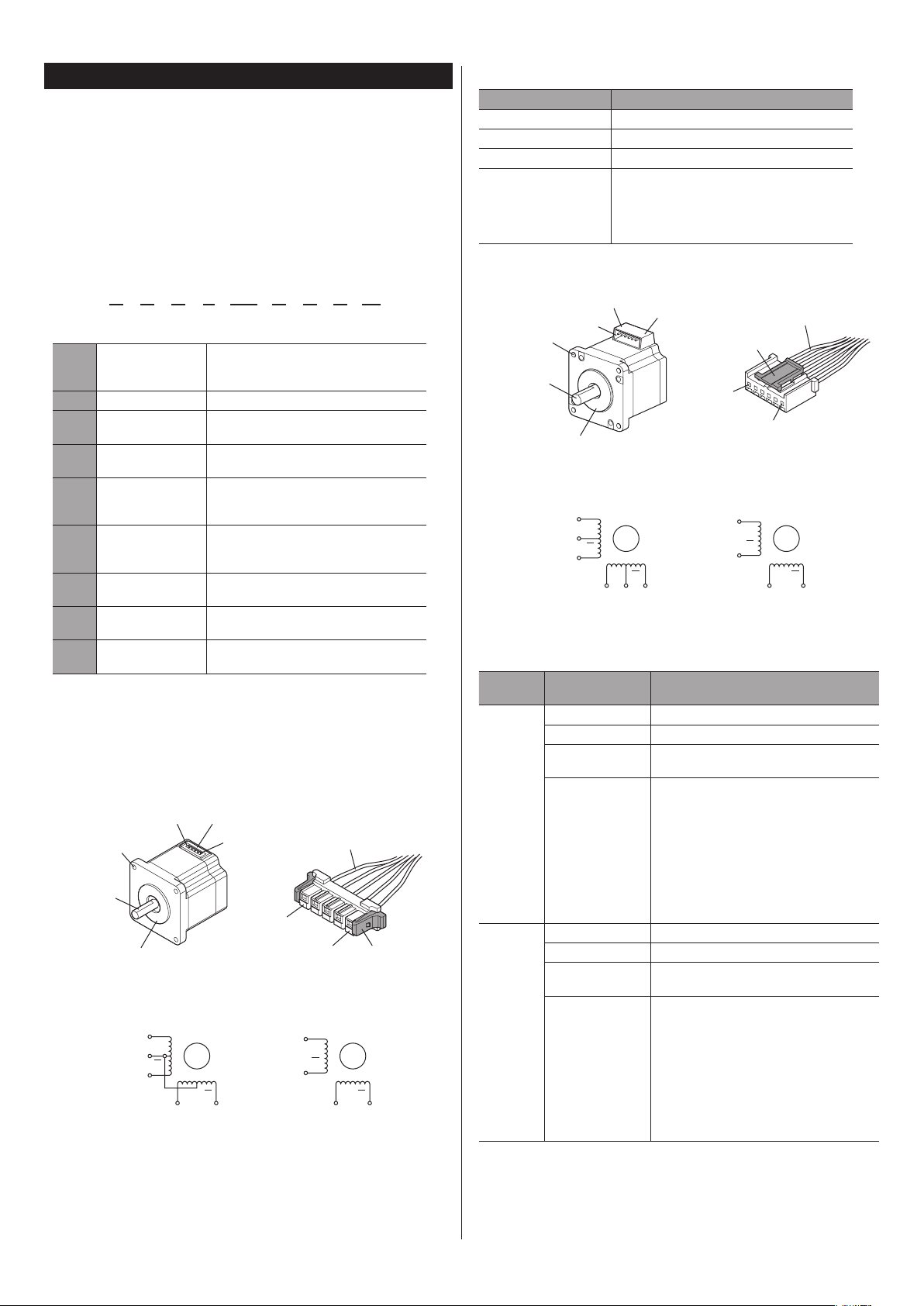
Names of parts
The pin numbers as well as the colors of lead wires are shown in the gures.
The connection diagrams show the supplied or accessory connection cable.
zMotors of Model A (connector type)
(4 places)
Output shaft
Pilot
Wiring connection diagram
1/Black
A
3/White
A
2/Green
Pin No.1
Pin No.1
Black
1/Black
2/Green
B B
* The pin No.3 is not used for the 4 lead wires type.
: 42 mm (1.65 in.)
4
: 56.4 mm (2.22 in.)
6
: 85 mm (3.35 in.)
9
Motor lead wires
Pin No.5
A
A
- L
Connector
Pin No.1
Connector
(4 places)
Output shaft
Wiring connection diagram
4/Black
5/Yellow
6/Green
A
A
B
B
3/
* The pin Nos.2 and 5 are not used for the 4 lead wires type.
Applicable connector/lead wire
Motor
model
PKP22
PKP23
PKP24
Type Model
Connector housing 51065-0600 (Molex)
Contact 50212-8XXX (Molex)
Designated crimping
tool
Applicable lead wire
Connector housing 51103-0600 (Molex)
Contact 50351-8XXX (Molex)
Designated crimping
tool
Applicable lead wire
Pin No.6
Connector lock
Pin No.6
Green
4/Black
6/Green
63819-0500 (Molex)
yWhen the current value is less than
1 A/phase: AWG28 to 24 (0.08 to 0.2 mm
yWhen the current value is 1 A/phase or more:
AWG26 to 24 (0.14 to 0.2 mm
yWhen the current value is 1.5 A/phase or more:
AWG24 (0.2 mm
− Outer sheath diameter:
ø0.8 to 1.4 mm (ø0.031 to 0.055 in.)
− Strip length of the insulation cover:
1.3 to 1.8 mm (0.051 to 0.071 in.)
63811-8100 (Molex)
yWhen the current value is less than
1.5 A/phase: AWG28 to 22 (0.08 to 0.3 mm
yWhen the current value is 1.5 A/phase or more:
AWG26 to 22 (0.14 to 0.3 mm
yWhen the current value is 2 A/phase or more:
AWG24 to 22 (0.2 to 0.3 mm
− Outer sheath diameter:
ø1.15 to 1.8 mm (ø0.045 to 0.071 in.)
− Strip length of the insulation cover:
2.3 to 2.8 mm (0.091 to 0.11 in.)
Pin No.1
A
A
3/Red 1/Blue
2
)
Motor lead wires
Connector
B
B
2
)
2
)
2
)
2
)
2
)
2
Page 3
Motor model Type Model
Motor lead wires
Mounting holes
Red Blue
BB
• Unipolar
• Bipolar
Red Blue
RedWhite Blue
• Unipolar
Bend excessively
More than 4 times
• Installation method 1 • Installation method 2
Connector housing 51067-0600 (Molex)
Contact 50217-9XXX (Molex)
Designated crimping tool 63811-8300 (Molex)
PKP26
Applicable lead wire
− AWG24 to 18 (0.2 to 0.75 mm
− Outer sheath diameter:
ø1.4 to 3 mm (ø0.055 to 0.118 in.)
− Strip length of the insulation cover:
3 to 3.5 mm (0.118 to 0.138 in.)
zMotors of Model C (lead wire type)
(4 places)
Output shaft
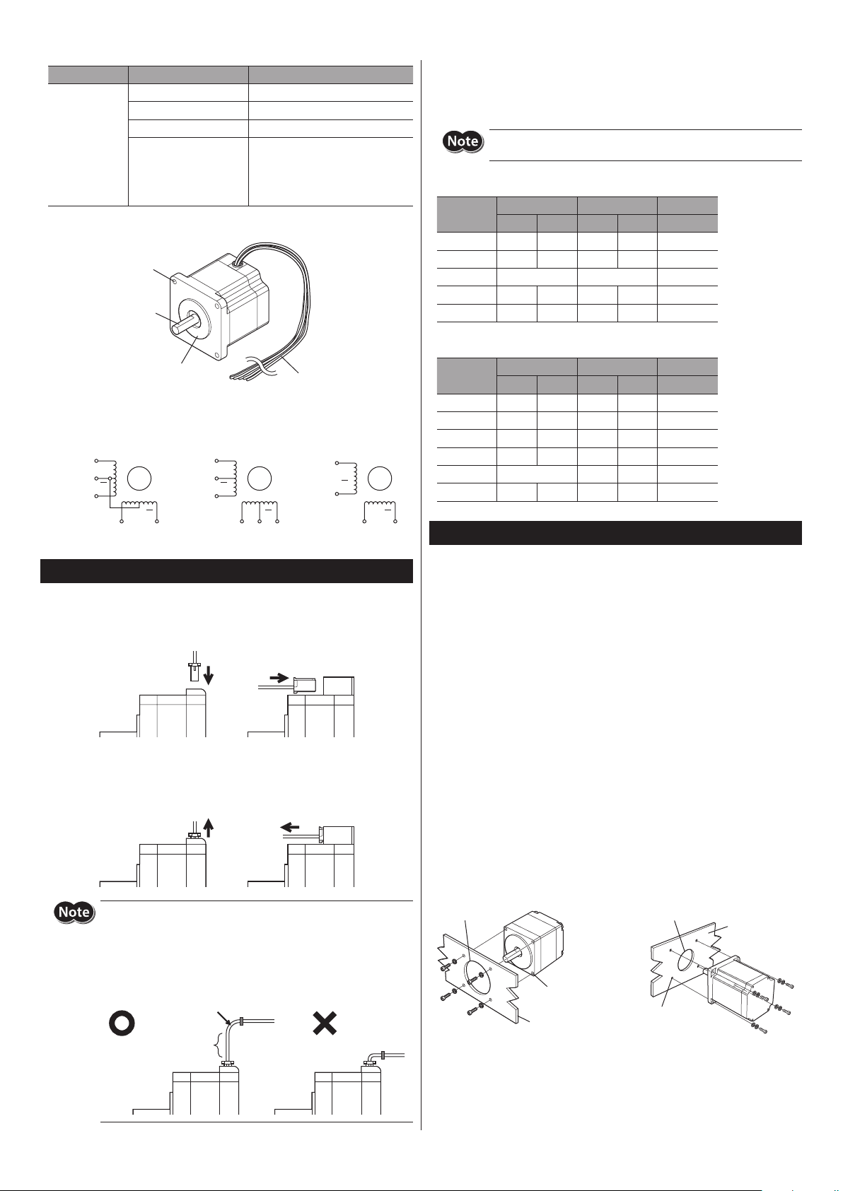
Connection with the drivers of Oriental Motor
Refer to the following table when connecting with the drivers of Oriental Motor.
“Color” in the table represents the colors of lead wires of the connection cable (supplied
or accessory).
2
)
•Connection with the
CN2 Pin No.
The motors of the model A and model B are dierent in pin assignments.
Wrong connection will not cause the motor to operate properly.
driver
CVD
Driver
1 4 Blue 1 Blue Blue
2 5 Red 3 Red Red
3 − − −
4 2 Green 6 Green Green
5 1 Black 4 Black Black
Model A Model B Model C
Pin No. Color Pin No. Color Color
Pilot
Wiring connection diagram
5 lead wires type
Black
A
Orange
A
Green
6 lead wires type
Black
Yellow
Green
B
A
A
B
4 lead wires type
Black
Green
B
A
A
B
Connection
•When inserting the connector
Hold the connector main body, and insert it in straight securely. Inserting the connector
in an inclined state may result in damage to connector or a connection failure.
•When pulling out the connector
Pull out the connector in straight while releasing the lock part of the connector. Having
the motor lead wires or pulling out the connector in a state of being locked may damage
the connector.
•Connection with the
Driver
CN3 Pin No.
1 4 Blue 1 Blue Blue
2 3 White 2 White White
3 5 Red 3 Red Red
4 1 Black 4 Black Black
5 − 5 Yellow Yellow
6 2 Green 6 Green Green
Model A Model B Model C
Pin No. Color Pin No. Color Color
CMD
driver
Installation
Location for installation
The motor is designed and manufactured for installation in equipment.
Install it in a well-ventilated location that provides easy access for inspection.
The location must also satisfy the following conditions:
yInside an enclosure that is installed indoors (provide vent holes)
yOperating ambient temperature −10 to +50 °C (+14 to +122 °F) (non-freezing)
yOperating ambient humidity 85% or less (non-condensing)
yArea that is free of explosive atmosphere or toxic gas (such as sulfuric gas) or liquid
yArea not exposed to direct sun
yArea free of excessive amount of dust, iron particles or the like
yArea not subject to splashing water (rain, water droplets), oil (oil droplets) or other
liquids
yArea free of excessive salt
yArea not subject to continuous vibration or excessive shocks
yArea free of excessive electromagnetic noise (from welders, power machinery, etc.)
yArea free of radioactive materials, magnetic elds or vacuum
y1,000 m (3,300 ft.) or lower above sea level
Installation method
Install the motor onto an appropriate at metal plate having excellent vibration
resistance and heat conductivity. When installing the motor, secure it with four bolts (not
supplied) through the four mounting holes provided. Do not leave a gap between the
motor and metal plate.
Secure the lead wires at the connection part to prevent the connection
part from receiving stress due to the exing of the lead wires or the lead
wires’ own mass. Also, do not excessively bend the lead wires near the
connection part of the connector. Applying stress on the motor lead wires
may cause poor contact or disconnection, leading to malfunction or heat
generation.
of the diameter of
the lead wires.
Have length allowances
Pilot holder
Mounting
holes
Metal plate
Mounting
holes
Pilot holder
Metal plate
3
Page 4
T
8:30
7:30
www
Schiessstraße 44, 40549 Düsseldor
T
www
T
www
T
www
T
www
T
www
• Please contact your nearest Oriental Motor oce for further information.
4-8-1Higashiueno
Japan
T
www
Tel:+852-2427-9800
Motor type Nominal size
PKP21
PKP22
PKP23
PKP24
PKP26
PKP29
M2 P0.4 0.25 (2.2) 2.5 (0.1)
M2.5 P0.45 0.5 (4.4) 2.5 (0.1)
M3 P0.5 1 (8.8) 4.5 (0.18)
M4 2 (17.7)
M5 3 (26.6)
Tightening
torque
[N·m (lb-in)]
Eective depth
of screw thread
[mm (in.)]
− 2
Installation
method
1
Installing a load
When connecting a load to the motor, align the centers of the motor output shaft and
load shaft. Be careful not to damage the output shaft or bearings when installing a
coupling or pulley to the motor output shaft.
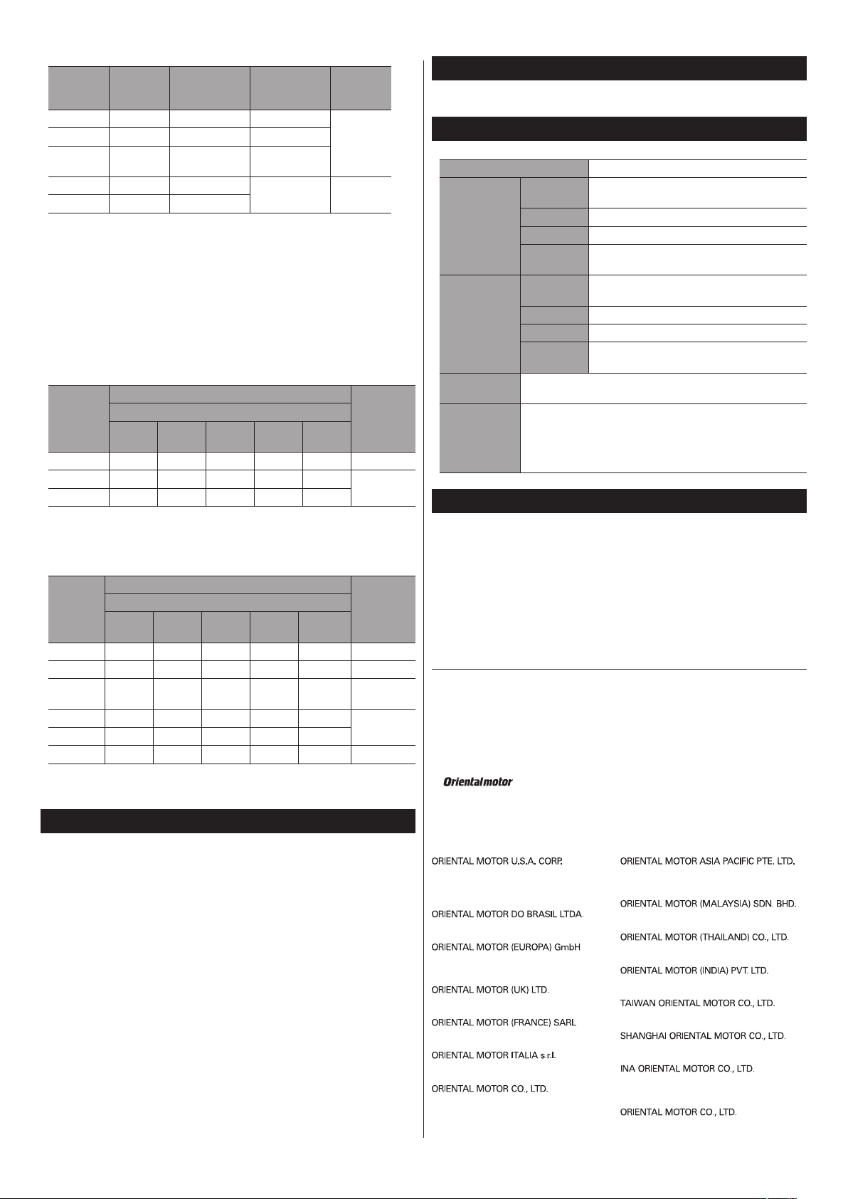
Permissible radial load and permissible axial load
The radial load and axial load on the motor output shaft must be kept the permissible
values listed in the table below.
zMotors of Model A
Permissible radial load [N (lb.)]
Motor type
PKP24
*1 61 (13.7) 73 (16.4) 90 (20) 140 (31) −
PKP26
*2 90 (20) 100 (22) 130 (29) 180 (40) 270 (60)
PKP26
*1 Output shaft diameter ø6.35 mm (ø0.25 in.)
*2 Output shaft diameter ø8 mm (ø0.31 in.)
Distance from the tip of motor output shaft
0 mm
(0 in.)
35 (7.8) 44 (9.9) 58 (13) 85 (19.1) − 15 (3.3)
5 mm
(0.20 in.)
10 mm
(0.39 in.)
15 mm
(0.59 in.)
20 mm
(0.79 in.)
Permissible
axial load
[N (lb.)]
30 (6.7)
zMotors of Model B and C
Permissible radial load [N (lb.)]
Motor type
PKP21
PKP22
PKP23
PKP24
*1 49 (11) 60 (13.5) 79 (17.7) 110 (24) −
PKP26
*2 61 (13.7) 73 (16.4) 90 (20) 110 (24) 160 (36)
PKP26
PKP29
*1 Output shaft diameter ø6.35 mm (ø0.25 in.)
*2 Output shaft diameter ø8 mm (ø0.31 in.)
Distance from the tip of motor output shaft
0 mm
(0 in.)
12 (2.7) 15 (3.3) − − − 3 (0.67)
25 (5.6) 34 (7.6) 52 (11.7) − − 5 (1.12)
20 (4.5) 25 (5.6) 34 (7.6) 52 (11.7) − 10 (2.2)
260 (58) 290 (65) 340 (76) 390 (87) 480 (108) 60 (13.5)
5 mm
(0.20 in.)
10 mm
(0.39 in.)
15 mm
(0.59 in.)
20 mm
(0.79 in.)
Permissible
axial load
[N (lb.)]
20 (4.5)
Maintenance/inspection
Specications
Check on the Oriental Motor Website for the product specications.
General specications
Degree of protection IP20
Operation
environment
Storage
environment,
Shipping
environment
Insulation
resistance
Dielectric
strength
Ambient
temperature
Humidity 85% or less (non-condensing)
Altitude Up to 1,000 m (3,300 ft.) above sea level
Surrounding
atmosphere
Ambient
temperature
Humidity 85% or less (non-condensing)
Altitude Up to 3,000 m (10,000 ft.) above sea level
Surrounding
atmosphere
100 MΩ or more when 500 VDC megger is applied between the
case and motor windings.
Sucient to withstand the following conditions applied between
the winding and the case for 1 minute:
PKP21, PKP22, PKP23, PKP24
•
PKP26
•
PKP29
•
−10 to +50 °C (+14 to +122 °F) (non-freezing)
No corrosive gas, dust, water or oil
−20 to +60 °C (−4 to +140 °F) (non-freezing)
No corrosive gas, dust, water or oil
: 0.5 kVAC 50/60 Hz
: 1.0 kVAC 50/60 Hz
: 1.5 kVAC 50/60 Hz
Regulations and standards
RoHS Directive
The products do not contain the substances exceeding the restriction values of RoHS
Directive (2011/65/EU).
yUnauthorized reproduction or copying of all or part of this manual is prohibited.
yOriental Motor shall not be liable whatsoever for any problems relating to industrial
property rights arising from use of any information, circuit, equipment or device
provided or referenced in this manual.
yCharacteristics, specications and dimensions are subject to change without notice.
yWhile we make every eort to oer accurate information in the manual, we welcome
your input. Should you nd unclear descriptions, errors or omissions, please contact the
nearest oce.
y
Japan and other countries.
© Copyright ORIENTAL MOTOR CO., LTD. 2012
is a registered trademark or trademark of Oriental Motor Co., Ltd., in
Published in February 2018
Inspection
It is recommended that periodic inspections are conducted for the items listed below
after each operation of the motor. If an abnormal condition is noted, discontinue any use
and contact your nearest Oriental Motor sales oce.
During inspection
yAre any of motor mounting screws loose?
yAre there any abnormal noises in the motor bearings (ball bearings) or other moving
parts?
yAre there any scratches, signs of stress in the motor lead wires?
yAre there any loose connections on the connector or driver?
yAre the motor’s output shaft and load shaft out of alignment?
Warranty
Check on the Oriental Motor Website or General Catalog for the product warranty.
Disposal
Dispose the product correctly in accordance with laws and regulations, or instructions of
local governments.
4
echnical Support Tel:(800)468-3982
A.M. to 5:00 P.M., P.S.T. (M-F)
A.M. to 5:00 P.M., C.S.T. (M-F)
.orientalmotor.com
el:+55-11-3266-6018
.orientalmotor.com.br
echnical Support Tel:00 800/22 55 66 22
.orientalmotor.de
el:01256-347090
.oriental-motor.co.uk
el:01 47 86 97 50
.orientalmotor.fr
el:02-93906346
.orientalmotor.it
,Taito-ku,Tokyo 110-8536
el:03-6744-0361
.orientalmotor.co.jp
f, Germany
Singapore
Tel:1800-8420280
www.orientalmotor.com.sg
Tel:1800-806161
www.orientalmotor.com.my
Tel:1800-888-881
www.orientalmotor.co.th
Tel:+91-80-41125586
www.orientalmotor.co.in
Tel:0800-060708
www.orientalmotor.com.tw
Tel:400-820-6516
www.orientalmotor.com.cn
Korea
Tel:080-777-2042
www.inaom.co.kr
Hong Kong Branch
 Loading...