

Page 1
HM-40002-2
OPERATING MANUAL
2-phase Stepping Motor
PK Series Standard Type
IP65 rated motor
PK29□EAT
Thank you for purchasing an Oriental Motor product.
This Operating Manual describes product handling procedures and safety
precautions.
・Please read it thoroughly to ensure safe operation.
・Always keep the manual where it is readily available.
Introduction
Before use
This product must be handled by qualified personnel
with expert knowledge of electrical and mechanical
engineering. Use the product correctly after thoroughly
reading the section “Safety precautions.”
This product is designed for use as an internal
component for general industrial equipment. Do not use
the product for any other purpose. Oriental Motor shall
not be liable whatsoever for any damage arising from
the failure to observe this warning.
Product overview
This product is a 2-phase stepping motor employing a
terminal-block connection method.
This product is recognized by UL and certified by CSA,
and bears the CE Marking (Low Voltage Directive) in
compliance with the EN Standards.
Applicable Standards
Certification
Body
Standards
File No.
UL 1004, UL 2111
CSA C22.2 No.100
CSA C22.2 No.77
UL E64199
EN 60950, EN 60034-1,
EN 60034-5, IEC 60664-1
Conforming to the
respective standards.
Degree of protection
IP65 (Excluding the gap between the shaft and
the flange)
Operating environment
Ambient
temperature
−10 to +50 °C (+14 to +122 °F)
(non-freezing)
Humidity 85% or less (non-condensing)
Altitude
Up to 1000 m (3300 ft.) above sea
level
Ambient
atmosphere
Free from corrosive gases
Installation conditions
Built-in component
Overvoltage category: II
Pollution degree: Class 3 (excluding installation
surface)
Protection against electric shock: Class I
equipment
The user is responsible for confirming the EMC
compatibility of the final equipment incorporating the
motor.
Hazardous substances
RoHS (Directive 2002/95/EC 27Jan.2003) compliant
Checking the product
Open the package and confirm that all of the following
items are available. Should you find any item missing or
damaged, contact the Oriental Motor sales office where
you purchased the product. Check the model of the
motor against the model number shown on the
nameplate.
• Motor 1 unit
• Short bars 4pcs. (packed in a plastic bag)
• OPERATING MANUAL 1 copy
• Model number
Motor frame size 9: 85 mm (3.35 in.)
E: 8 terminals
Motor identification
A: Single shaft
PK 2 9 6 E A T
PK series
Motor case length
2: 2-phase
• Product types
PK296EAT PK299EAT PK2913EAT
The connection methods and rated currents are listed
below.
Bipolar connection
Model
Unipolar
connection
Parallel Series
PK296
PK299
4.5 A/phase 6.3 A/ phase 3.18 A/ phase
PK2913 4.0 A/ phase 5.6 A/ phase 2.8 A/ phase
Safety precautions
The motor is designed for incorporation into industrial
equipment. Touching the motor during operation may
result in bodily injury or property damage, since the
output shaft is rotating and the surface remains very hot.
To prevent injury or damage to the motor, be sure the
motor is handled and operated only by qualified
personnel familiar with operations involving electronic
equipment.
Warning
Handling the product without observing the instructions
that accompany a “Warning” symbol may result in death
or serious bodily injury.
• Do not use the motor in explosive or corrosive
environments, in the presence of flammable gases,
near combustible materials, or locations subjected to
the splashing of oil or other hazardous liquids. Doing
so may result in fire, electric shock or injury.
• Turn off the power before working on the product.
Failure to do so may result in electric shock.
• Provide a measure to retain the position of the
movable part of the equipment when the product is
used in a vertical application. The motor loses its
holding torque when the power is cut off. Without
appropriate measures the movable part will descend,
resulting in injury or damage to the equipment.
• Install the motor in the enclosure to avoid contact with
the hands, or provide sufficient earthing. Failure to do
so may result in electric shock.
• Connect the product correctly and securely according
to the wiring diagram. Failure to do so may result in
fire or electric shock.
• After connecting the cable, securely fix and tighten
the terminal box and cable clamp. Failure to do so
may result in fire or electric shock.
• Turn off the power in case of a power failure. Failure
to do so may result in injury or damage to the
equipment when the motor starts suddenly upon the
recovery of power.
• Do not disassemble or modify the motor. This may
cause electric shock or injury.
Caution
Handling the product without observing the instructions
that accompany a “Caution” symbol may result in bodily
injury or property damage.
• Do not use the motor beyond its specifications. Doing
so may result in electric shock, injury or damage to
the equipment.
• Do not touch the motor while the motor is conducting
current. Doing so may result in burns.
• When connecting the terminal block or protective earth
terminal, use a round terminal with insulated coating.
Failure to do so may result in fire or electric shock.
• Do not carry the motor by its output shaft. Doing so
may result in injury.
• Securely fix the motor to an appropriate metal plate.
Failure to do so may result in injury or damage to the
equipment.
• Protect the rotating part of the motor (output shaft )
with a cover. Failure to do so may result in injury.
• Conduct the insulation resistance measurement or
withstand voltage test separately on the motor and
the driver. Failure to do so may result in damage to
equipment.
• Immediately when trouble has occurred, stop running
and turn off the power. Failure to do so may result in
fire, electric shock or injury.
• To dispose of the motor, disassemble it into parts and
components as much as possible and dispose of
individual parts/components as industrial waste.
• Provide an emergency-stop device or
emergency-stop circuit external to the equipment so
that the entire equipment will operate safely in the
event of a system failure or malfunction. Failure to do
so may result in injury.
Precautions for use
• Drive unit
Use a motor driver unit appropriate for the method of
motor connection.
• Connecting the motor
Use a multi-core cable of AWG22 to 16 (0.3 to
1.25 mm
2
) [7 to 13 mm (0.28 to 0.51 in.) in outer
diameter] for motor connection. Motor cable (with
protective earth conductor) is available as an option
(sold separately). For details, contact your nearest
Oriental Motor office.
Strip away 40 to 50 mm (1.57 to 1.97 in.) of sheath from
the end of the cable. Stripping the cable sheath by more
than 50 mm (1.97 in.) will reduce the sealing effect of
the cable clamp.
• Cable clamp
“Cable clamp” is a section through which a cable
passes. The cable clamp conforms to the IP65
specification and consists of the cap, gasket and
receptacle. To ensure watertightness at the cable clamp,
tighten the cap after confirming that the cover of the
connection cable is securely sealed by the gasket.
• Motor case temperature
The motor is designed to the class B insulation
specification. When operating the motor, keep the motor
case temperature to 100 °C (212 °F) or below.
Operating the motor at temperatures above 100 °C
(212 °F) will shorten the life of the motor coil and ball
bearing. [The maximum temperature is 75 °C (167 °F) if
the equipment is to receive UL/CSA certification,
because the motor must conform to the class A
insulation requirement.]
Installation
Installation requirements
The motor is designed to be a built-in component. It
must be used in an environment conforming to
overvoltage category II, pollution degree of class 3 and
protection against electric shock of class I equipment.
Degree of protection: IP65 (Excluding the gap between
the shaft and the flange)
Install the motor in a well-ventilated location that
provides easy access for inspection. The locaton must
also satisfy the following conditions:
• Inside an enclosure that is installed indoors (provide
vent holes)
• Operating ambient temperature: −10 to +50 °C (+14
to +122 °F) (non-freezing)
• Operating ambient humidity: 85% or less
(non-condensing)
• Area that is free of explosive atmosphere or toxic gas
(such as sulfuric gas) or liquid
• Area not exposed to direct sun
• Area free of excessive salt
• Area not subject to continuous vibration or excessive
shocks
• Area free of excessive electromagnetic noise (from
welders, power machinery, etc.)
• Area free of radioactive materials, magnetic fields or
vacuum
Page 2
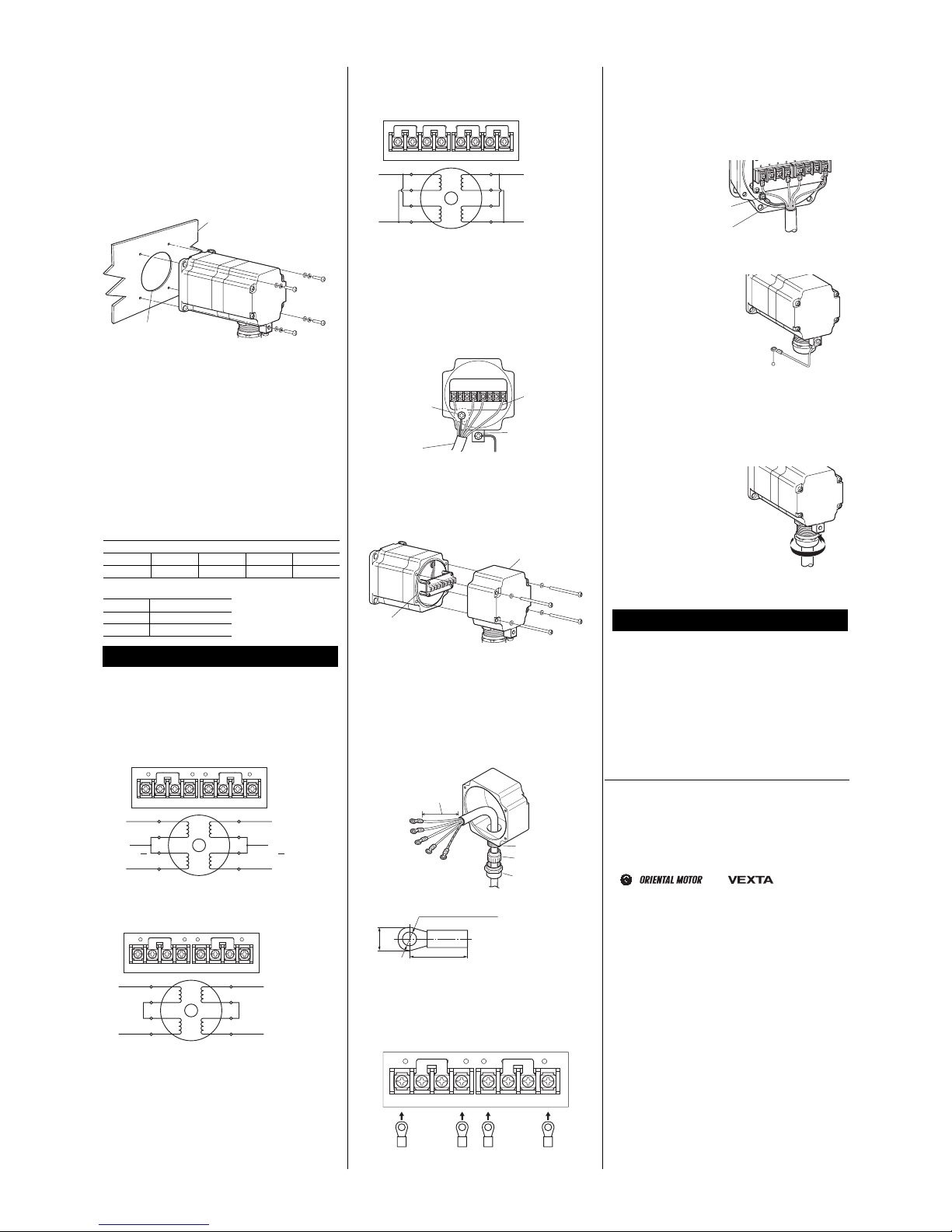
Installation method
Mount the motor on the smooth surface of a metal plate.
When installing the motor, secure it with four bolts (not
supplied) through the four mounting holes provided in
the motor’s installation surface, so as to leave no gaps
between the installation surface and metal plate.
Bolt size: M5
Tightening torque: 3 N·m (420 oz-in)
Insert the pilot located on the motor’s installation
surface into the mounting plate’s countersunk or
through hole.
Metal plate
Pilot holder
(countersunk or through hole)
Installing the load
When installing a load to the motor, align the centers of
the motor’s output shaft and load shaft.
Be careful not to damage the output shaft or bearings
within when installing a flexible coupling or pulley to the
motor’s output shaft.
Permissible overhung load and
permissible thrust load
The overhang load of the motor’s output shaft must not
exceed the permissible values shown in the table below.
The thrust value must be kept at or below the mass (
∗
)
of the motor.
• Permissible overhung load [N (lb.)]
Distance from the tip of motor’s output shaft [mm (in.)]
0 (0) 5 (0.20) 10 (0.39) 15 (0.59) 20 (0.79)
260 (58) 290 (65) 340 (76) 390 (87) 480 (108)
• Permissible thrust load [kg (lb.)]
PK296 2.1 (4.62)∗
PK299 3.2 (7.04)∗
PK2913 4.3 (9.46)∗
Connection
Use the supplied shorting bars to provide a connection
of the desired method.
Wiring diagrams
• Unipolar connection
Connect the supplied shorting bars (two pieces) as
shown in the figure:
1234 5678
1
3
2
+COM
Phase A Phase B
+COM
4
5
7
6
8
Phase A
Phase B
• Series bipolar connection
Connect the supplied shorting bars (two pieces) as
shown in the figure:
1234 5678
1
3
2
Phase A Phase B
4
5
7
6
8
• Parallel bipolar connection
Connect the supplied shorting bars (four pieces) as
shown in the figure:
1234 5678
1
3
2
Phase A Phase B
4
5
7
6
8
Connection method
Connect the respective wires as illustrated below.
Connect either the internal protective earth terminal or
external protective earth terminal to the ground. Use the
internal protective earth terminal in a corrosive
environment. If the wiring distance between the motor
and driver is long, use the external protective earth
terminal. Use a earthing conductor thicker than AWG18
(0.75 mm
2
).
Protective earth
conductor for external
protective earth
terminal
(AWG18 or more)
Motor lead wires
(AWG22 to 16)
Protective earth
conductor for internal
protective earth
terminal
(AWG18 or more)
Multi-core cable
[Outer diameter: 7 to 13 mm
(0.28 to 0.51 in.)]
1. Remove the terminal box
Loosen the mounting screws (M3) for securing the
terminal box, then remove the terminal box from the
motor.
Terminal box
O-ring
2. Repair the connection cable
• Stripping the cable sheath by more than 50 mm
(1.97 in.) from the end of the cable will reduce the
sealing effect of the cable clamp.
• Crimp a round crimp terminal with insulated coating
(M3) to the motor lead wire.
• When using the internal protective earth terminal,
crimp a round terminal with insulated coating (M4) to
the protective earth conductor.
40 to 50 mm
(1.57 to 1.97 in.)
Receptacle
Gasket
Cap
Ø3.2 mm (Ø0.13 in.)
or more
9 mm (0.35 in.)
or more
6.2 mm (0.24 in.)
or less
Tightening torque:
0.8 N·m (113 oz-in)
3. Connect the terminal block
Connect the motor lead wires to the terminal block and
tighten the screws.
Connect the motor lead wires to the short bars in the
direction shown below.
1234 5678
4. Connect the protective earth terminal
Connect to the minimum distance.
• Using the internal protective earth terminal
Connect the protective earth conductor to the protective
earth terminal.
Tightening torque: 1.2 N·m (170 oz-in)
Protective earth terminal
Protective earth conductor
(AWG18 or more)
• Using the external protective earth terminal
Two screw holes are
provided for connecting the
protective earth terminal.
Use a round terminal with
insulated coating (M4) to
connect one of the two
points to the ground.
Tightening torque:
1.2 N·m (170 oz-in)
PE
5. Install the terminal box
Confirm that an O-ring is set in the groove, align the
motor case and terminal cover, then tighten the
mounting screws (M3) for securing the terminal cover.
Tightening torque: 0.5 N·m (71 oz-in)
6. Tighten the cable cap
Place the gasket on the
receptacle and tighten the
cap. Before tightening the
cap, confirm that the
sheath of the cable is
sealed by the gasket.
Tightening torque:
4.0 to 5.0 N·m (560 to
710 oz-in)
Adjust the tightening torque
depending on the diameter
and material of the cable.
Inspection
It is recommended that the following items be checked
regularly after the motor has been operated. Should any
abnormality be found, stop using the motor and contact
your nearest Oriental Motor office.
• Is there any abnormal noise coming from the motor’s
bearings (ball bearings) or other parts?
• Is there a loose terminal box or cable cap?
• Is there any scratch or sign of stress on the
connection cable?
• Are the output shaft and load shaft properly aligned at
their centers?
• Unauthorized reproduction or copying of all or part of
this Operating Manual is prohibited.
• Characteristics, specifications and dimensions are
subject to change without notice.
• While we make every effort to offer accurate
information in the manual, we welcome your input.
Should you find unclear descriptions, errors or
omissions, please contact the nearest office.
•
, and are trademarks
of Oriental Motor Co., Ltd., and are registered in
Japan and other countries.
© Copyright ORIENTAL MOTOR CO., LTD. 2006
Printed on Recycled Paper
ORIENTAL MOTOR U.S.A. CORP.
Technical Support Line Tel:(800)468-3982
A
vailable from 7:30 AM to 5:00 PM, P.S.T.
E-mail: [email protected]
ORIENTAL MOTOR (EUROPA) GmbH
Headquarters and Düsseldorf Office
Tel:0211-5206700
ORIENTAL MOTOR (UK) LTD. Tel:01256-347090
ORIENTAL MOTOR (FRANCE) SARL Tel:01 47 86 97 50
ORIENTAL MOTOR ITALIA s.r.l. Tel:02-93906346
TAIWAN ORIENTAL MOTOR CO., LTD.
Tel:(02)8228-0707
SINGAPORE ORIENTAL MOTOR PTE. LTD.
Tel:(6745)7344
ORIENTAL MOTOR (MALAYSIA) SDN. BHD.
Tel:(03)79545778
INA ORIENTAL MOTOR CO., LTD. KOREA
Tel:(032)822-2042~3
ORIENTAL MOTOR CO., LTD.
Headquarters Tokyo, Japan Tel:(03)3835-0684
· Please contact your nearest Oriental Motor office for further
information.
Page 3
HM-40002-2
取扱説明書
2 相ステッピングモーター
PK シリーズ 標準タイプ 保護等級 IP65 仕様
PK29□EAT
お買い上げいただきありがとうございます。
この取扱説明書には、製品の取り扱いかたや安全上の注意事項を示しています。
・取扱説明書をよくお読みになり、製品を安全にお使いください。
・お読みになったあとは、いつでも見られるところに必ず保管してください。
はじめに
お使いになる前に
製品の取り扱いは、適切な資格を有する人が行なっ
てください。お使いになる前に、「安全上のご注意」を
よくお読みのうえ、正しくお使いください。
この製品は、一般的な産業機器の機器組み込み用と
して設計されています。その他の用途には使用しな
いでください。この警告を無視した結果生じた損害の
補償については、当社は一切その責任を負いません
ので、あらかじめご了承ください。
製品の概要
この製品は、端子台接続方式を採用した2 相ステッピ
ングモーターです。
この製品は、UL 規格、CSA 規格の認定を取得し、
EN 規格にもとづいて CE マーキング(低電圧指令)を
実施しています。
適用規格 認定機関 規格ファイル No.
UL 1004、UL 2111
CSA C22.2 No.100
CSA C22.2 No.77
UL E64199
EN 60950、EN 60034-1、
EN 60034-5、IEC 60664-1
規格対応品
保護等級 IP65(モーターシャフト貫通部を除く)
周囲温度 −10~+50 °C(凍結しないこと)
湿 度 85%以下(結露しないこと)
高 度 海抜 1000 m 以下
使用環境
雰囲気 腐食性ガスがないこと
設置条件 機器組み込み
過電圧カテゴリー:Ⅱ
汚染度:クラス 3(取付面を除く)
感電保護:クラスⅠ機器
EMC の適合性は、お客様の責任で確認していただく
必要があります。
有害物質
RoHS(EU 指令 2002/95/EC 27Jan.2003)適合
製品の確認
パッケージを開封し、次の付属品がすべて揃っている
ことを確認してください。不足したり、破損しているとき
は、お買い求めの支店または営業所までご連絡くだ
さい。モーターの品名は、銘板に記載された品名で確
認してください。
モーター 1 台
ショートバー 4 個(袋詰め)
取扱説明書 1 部
• 品名の見方
䊝䊷䉺䊷⼂
A䋺 ゲ
PK 2 9 6 E A T
PK䉲䊥䊷䉵
䊝䊷䉺䊷ขઃⷺኸᴺ 9䋺85 mm
䊝䊷䉺䊷䉬䊷䉴㐳䈘
E䋺8┵ሶ
2䋺2⋧
• 製品の種類
PK296EAT PK299EAT PK2913EAT
結線方式と定格電流は、次のとおりです。
バイポーラ結線
品 名 ユニポーラ結線
パラレル シリーズ
PK296
PK299
4.5 A/相 6.3 A/相 3.18 A/相
PK2913 4.0 A/相 5.6 A/相 2.8 A/相
安全上のご注意
モーターは、産業機器への組み込み用に設計されて
います。運転中は、出力軸が回転し、表面が高温に
なるため、身体への危険、または物的損害が発生す
る可能性があります。けがやモーターの損害を防止し、
回避するため、電子機器の作業に精通した有資格者
のみがモーターの取り扱い・操作を行なってください。
この警告事項に反した取り扱いをすると、死亡または
重傷を負う場合がある内容を示しています。
• 爆発性雰囲気、引火性ガスの雰囲気、腐食性の雰
囲気、可燃物のそば、および油などの有害な液体
がかかる場所では使用しないでください。火災・感
電・けがの原因になります。
• 作業をするときは、電源を切ってから行なってくださ
い。感電の原因になります。
• 昇降装置に使用するときは、可動部の位置保持対
策を行なってください。モーターは電源オフ時に、保
持力がなくなります。可動部が落下して、けが・装置
破損の原因になります。
• 設置するときは、モーターに手が触れないようにす
るか、接地してください。感電の原因になります。
• 接続は接続図にもとづき、確実に行なってください。
火災・感電の原因になります。
• ケーブル接続後は、端子箱、ケーブルクランプを確
実に固定、締め付けてください。火災・感電の原因
になります。
• 停電したときは、電源を切ってください。停電復旧時
にモーターが突然起動して、けが・装置破損の原因
になります。
• モーターは、分解・改造しないでください。感電・け
がの原因になります。
この注意事項に反した取り扱いをすると、傷害を負う
または、物的損害が発生する場合がある内容を示し
ています。
• モーターの仕様値を超えて使用しないでください。
感電・けが・装置破損の原因になります。
• モーターに通電中は、モーターに触れないでくださ
い。やけどの原因になります。
• 端子台や保護接地端子と接続するときは、絶縁被
覆付き丸型端子を使用してください。火災・感電の
原因になります。
• 持ち運ぶときは、モーターの出力軸を持たないでく
ださい。けがの原因になります。
• モーターは、金属板に確実に固定してください。け
が・装置破損の原因になります。
• モーターの回転部(出力軸)に、カバーを設けてくだ
さい。けがの原因になります。
• 絶縁抵抗測定、絶縁耐圧試験は、モーターとドライ
バそれぞれで行なってください。製品破損の原因に
なります。
• 異常が発生したときは、ただちに運転を停止して、
電源を切ってください。火災・感電・けがの原因にな
ります。
• モーターを廃棄するときは、できるだけ分解し、産業
廃棄物として処理してください。
• 装置の故障や動作の異常が発生したときは、装置
全体が安全な方向へはたらくよう非常停止装置、ま
たは非常停止回路を外部に設置してください。けが
の原因になります。
使用上のご注意
• 駆動装置
モーターの結線方式に合った駆動装置を使用してく
ださい。
• モーターの接続
モーターの接続は AWG22~16(0.3~1.25 mm2)の
多心ケーブル(外径 7~13 mm)を使用してください。
オプション(別売)でモーター接続用ケーブル(保護接
地線付)を用意しています。詳しくは、最寄りのお客様
ご相談センターにお問い合わせください。
ケーブル先端の被覆は、40~50 mm 剥いてください。
50 mm 以上剥くと、ケーブルクランプのシール効果が
失われます。
• ケーブルクランプ
ケーブルクランプとは、IP65 仕様に対応したケーブル
貫通部のことで、キャップ、ガスケット、およびレセプタ
クルで構成されています。ケーブルクランプの防水性
を確保するため、ガスケットで多心ケーブルの被覆が
確実にシールされていることを確認してから、キャップ
を締め付けてください。
• モーターケース温度
モーターの絶縁階級は B 種絶縁です。モーターを運
転するときは、モーターケースの温度を 100 °C 以下
に抑えてください。100 °C を超えて運転すると、モー
ターの巻線やボールベアリングの寿命が短くなります。
(UL/CSA 規格取得時は、モーター部 A 種絶縁のた
め、75 ºC 以下となります)
設 置
必要条件
モーターは、機器組み込み、過電圧カテゴリー:Ⅱ、
汚染度:クラス 3、感電保護:クラスⅠ機器の環境で
使用するよう設計されています。
保護等級 IP65(モーターシャフト貫通部を除く)
モーターは、風通しがよく、点検が容易な、次の場所
に設置してください。
• 屋内に設置された筐体内(換気口を設けてくだ さい)
• 使用周囲温度 −10~+50 ºC(凍結しないこと)
• 使用周囲湿度 85%以下(結露しないこと)
• 爆発性雰囲気、有害なガス(硫化ガスなど)、および
液体のないところ
• 直射日光が当たらないところ
• 塩分の少ないところ
• 連続的な振動や過度の衝撃が加わらないところ
• 電磁ノイズ(溶接機、動力機器など)が少ないところ
• 放射性物質や磁場がなく、真空でないところ
Page 4
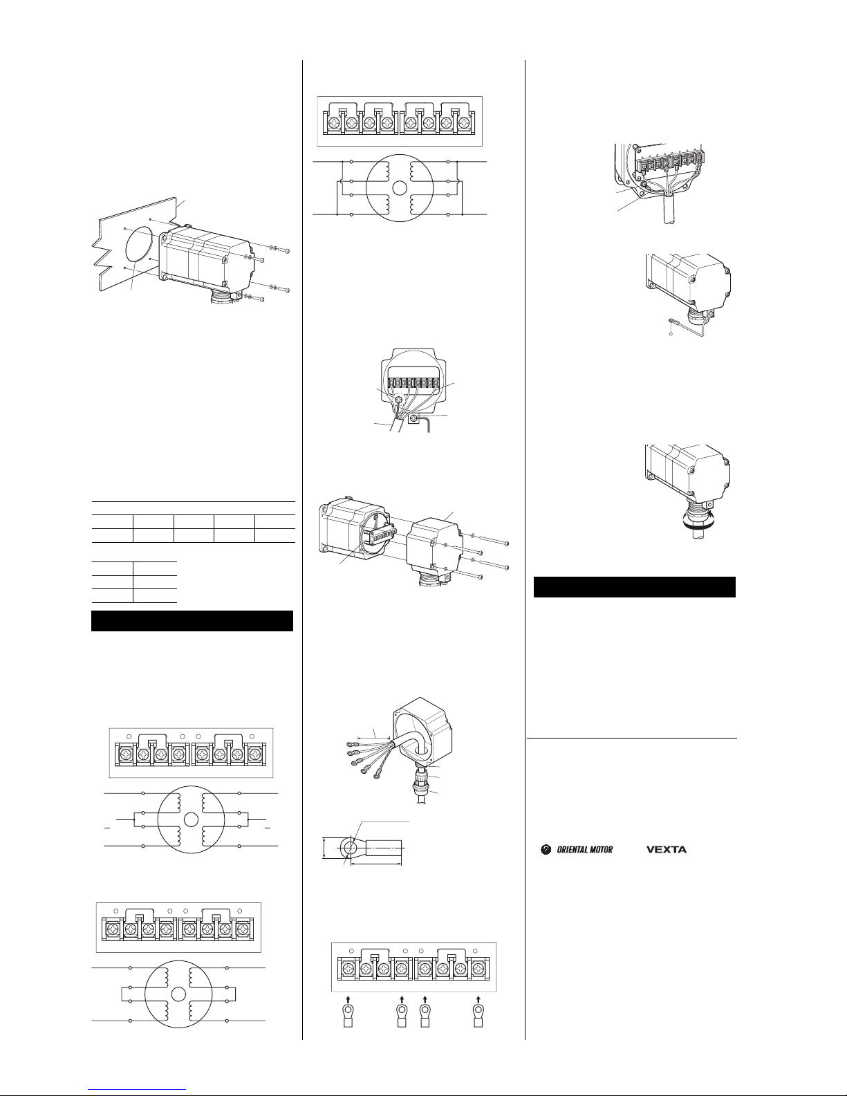
設置方法
モーターは、平滑な金属板に設置してください。
モーター取付面にある 4 か所の取付穴を使用して、
金属板との間にすき間ができないように、4 本のボル
ト(付属していません)で固定してください。
ボルトの呼び:M5
締付トルク:3 N·m
モーター取付面にあるインローは、座ぐりまたは貫通
加工されたインロー受けにはめこんでください。
㊄ዻ᧼
䉟䊮䊨䊷ฃ䈔
䋨ᐳ䈓䉍䉁䈢䈲⽾ㅢⓣ䋩
負荷の取り付け
モーターに負荷を取り付けるときは、モーター出力軸
と負荷の軸中心線を揃えてください。
フレキシブルカップリングやプーリーをモーター出力
軸に取り付けるときは、出力軸や軸受けに損傷を与
えないでください。
許容オーバーハング荷重と許容スラ
スト荷重
モーター出力軸のオーバーハング荷重は、表の値以
下にしてください。
∗
印はモーター質量(kg)です。スラ
スト荷重は、モーター自重以下にしてください。
• 許容オーバーハング荷重(N)
モーター出力軸先端からの距離(mm)
0 5 10 15 20
260 290 340 390 480
• 許容スラスト荷重
PK296 2.1∗
PK299 3.2∗
PK2913 4.3∗
接 続
付属のショートバーを使用して、結線方式を選択して
ください。
接続図
• ユニポーラ結線
ショートバー(2 個)を図のように接続してください。
1234 5678
1
3
2
+COM
A⋧ B⋧
+COM
4
5
7
6
8
A⋧ B⋧
• シリーズバイポーラ結線
ショートバー(2 個)を図のように接続してください。
1234 5678
1
3
2
A
⋧ B⋧
4
5
7
6
8
• パラレルバイポーラ結線
ショートバー(4 個)を図のように接続してください。
1234 5678
1
3
2
A
⋧ B⋧
4
5
7
6
8
接続方法
図のように接続してください。
内部保護接地端子と外部保護接地端子のどちらかを
接地してください。腐食の可能性がある使用環境では、
内部保護接地端子をお使いください。また、モーター
とドライバの配線距離が長い場合は、外部保護接地
端子をお使いください。接地線は、AWG18
(0.75 mm
2
)より太いものを使用してください。
ᄙᔃ䉬䊷䊑䊦
䋨ᄖᓘ7䌾13 mm䋩
ᄖㇱ⼔ធ┵ሶ
⼔ធ✢
䋨AWG18 એ䋩
䊝䊷䉺䊷✢
䋨AWG22 䌾16䋩
ౝㇱ⼔ធ┵ሶ
⼔ធ✢
䋨AWG18 એ䋩
1. 端子箱の取り外し
端子箱取付ねじ(M3)を緩め、端子箱をモーター部か
ら取り外します。
┵ሶ▫
O䊥䊮䉫
2. 接続ケーブルの加工
• ケーブル先端の被覆を 50 mm 以上剥くと、ケーブ
ルクランプのシール効果が失われます。
• 絶縁被覆付き丸型圧着端子(M3)をモーター線に
圧着します。
• 内部で接地するときは、絶縁被覆付き丸型端子
(M4)を保護接地線に圧着します。
40䌾50 mm
䊧䉶䊒䉺䉪䊦
䉧䉴䉬䉾䊃
䉨䊞䉾䊒
Ø3.2 mmએ
9 mmએ
6.2 mmએ
締付トルク:0.8 N·m
3. 端子台への接続
モーター線を端子台に接続し、ねじを締め付けます。
ショートバーとモーター線は、図に示した向きで接続し
てください。
1234 5678
4. 保護接地端子への接続
最短距離で接地してください。
• 内部保護接地端子を使う場合
保護接地線を保護接地端子に接続します。
締付トルク:1.2 N·m
⼔ធ✢
䋨AWG18 એ䋩
⼔ធ┵ሶ
• 外部保護接地端子を使う場合
保護接地端子のねじ穴
は 2 か所あります。絶縁
被覆付き丸型端子(M4)
を使用して、どちらかを接
地してください。
締付トルク:1.2 N·m
PE
5. 端子箱の取り付け
O リングが溝に装着されていることを確認し、端子箱
の向きをモーターケースに合わせて、端子箱取付ね
じ(M3)を締め付けます。
締付トルク:0.5 N·m
6. キャップの締め付け
ガスケットをレセプタクル
にはめ込み、多心ケーブ
ルの被覆がガスケットで
確実にシールされている
ことを確認してから、
キャップを締め付けます。
締付トルク: 4.0~5.0 N·m
締付トルクは、ケーブル
径・材質により調整してく
ださい。
点 検
モーターの運転後は、定期的に次の項目について点
検することをおすすめします。異常があるときは使用
を中止し、お客様ご相談センターにお問い合わせくだ
さい。
• モーターの軸受部(ボールベアリング)などから異
常な音が発生していないか。
• 端子箱やキャップに緩みがないか。
• 多心ケーブルに傷やストレスがないか。
• 出力軸と負荷軸に心ズレが出ていないか。
• この取扱説明書の一部または全部を無断で転載、複
製することは、禁止されています。
• 製品の性能、仕様および外観は改良のため予告なく変
更することがありますのでご了承ください。
• 取扱説明書には正確な情報を記載するよう努めていま
すが、万一ご不審な点や誤り、記載もれなどにお気づ
きの点がありましたら、最寄りのお客様ご相談センター
までご連絡ください。
•
、 、および は、日本そ
の他の国で登録されたオリエンタルモーター株式会社
の商標です。
© Copyright ORIENTAL MOTOR CO., LTD. 2006
䈖䈱ขᛒ⺑ᦠ䈲ౣ↢⚕䉕↪䈚䈩䈇䉁䈜䇯
䉥䊥䉣䊮䉺䊦䊝䊷䉺䊷ᩣᑼળ␠
http://www.orientalmotor.co.jp/
䃂㩷ຠ䈮䈧䈇䈩䈱䈗⾰䇮䈗⋧⺣䈲䈍ቴ᭽䈗⋧⺣䉶䊮䉺䊷䈻
㩷 䈍䈇ว䉒䈞䈒䈣䈘䈇䇯
㩷 䊐䊥䊷䉮䊷䊦䋨ήᢱ䋩䈪䈜䇯៤Ꮺ㔚䊶PHS䈭䈬䈪䉅䈗↪䈏
㩷 น⢻䈪䈜䇯
㩷 ฃઃᤨ㑆㩷㩷㩷ᐔᣣ㩷9:00䌾18:30 ᦐᣣ㩷9:00䌾17:30
᧲㩷 㩷 TEL 0120-925-410 FAX 0120-925-601
ฬฎ㩷ደ㩷 TEL 0120-925-420 FAX 0120-925-602
ᄢ㩷 㒋㩷 TEL 0120-925-430 FAX 0120-925-603
 Loading...