

Oriental motor PK264-E2.0B, PK266-E2.0A, PK264M-E2.0A, PK264M-E2.08, PK266M-E2.0A Operating Manual
...Page 1
1
HP-4169-2
Introduction
Before using the driver
Only qualified personnel should work with the product.
Use the product correctly after thoroughly reading the section “Safety
precautions.”
The product described in this manual has been designed and
manufactured for use in general industrial machinery, and must not be
used for any other purpose. For the power supply use a DC power
supply with reinforced insulation on its primary and secondary sides.
Oriental Motor Co., Ltd. is not responsible for any damage caused
through failure to observe this warning.
OPERATING MANUAL
Microstep Driver for 2-Phase
Stepping Motor
Thank you for purchasing an Oriental Motor product.
This Operating Manual describes product handling procedures and
safety precautions.
• Please read it thoroughly to ensure safe operation.
• Always keep the manual where it is readily available.
Caution
• Do not use the driver beyond its specification, or injury or damage
to equipment may result.
• Do not touch the driver’s heat sink during operation or immediately
after stopping. The surface is hot and may cause a burn.
• Keep the area around the driver free of combustible materials in
order to prevent fire or a burn.
• To prevent the risk of damage to equipment, leave nothing around
the driver that would obstruct ventilation.
• Use a motor and driver only in the specified combination. An
incorrect combination may cause a fire.
• To avoid injury, remain alert during operation so that the motor can
be stopped immediately in an emergency.
• Before supplying power to the driver, turn all input signals to the
driver to “OFF”. Otherwise, the motor may start suddenly and
cause injury or damage to equipment.
• When an abnormality is noted, stop the operation immediately, or
fire or injury may occur.
• When disposing of the driver, treat it as industrial waste.
Precaution
Checking the product
Upon opening the package, verify that the items listed below are
included.
Report any missing or damaged items to the branch or sales office
from which you purchased the product.
• Driver 1 unit
• Operating manual 1 copy
Overview of the product
This is a 2-phase microstep driver for use with a 2-phase stepping
motors. The use of a microstep drive, which electrically divides the
basic step angle of a 2-phase motor, offers reduced vibration and
noise in the low-speed range compared with the levels in full-step
mode.
• Do not turn the C.OFF (All windings off) input to “ON” while the
motor is operating. The motor will stop and lose its holding ability,
which may result in injury or damage to the equipment.
• Do not disassemble or modify the driver. This may cause injury.
Refer all such internal inspections and repairs to the branch or sales
office from which you purchased the product.
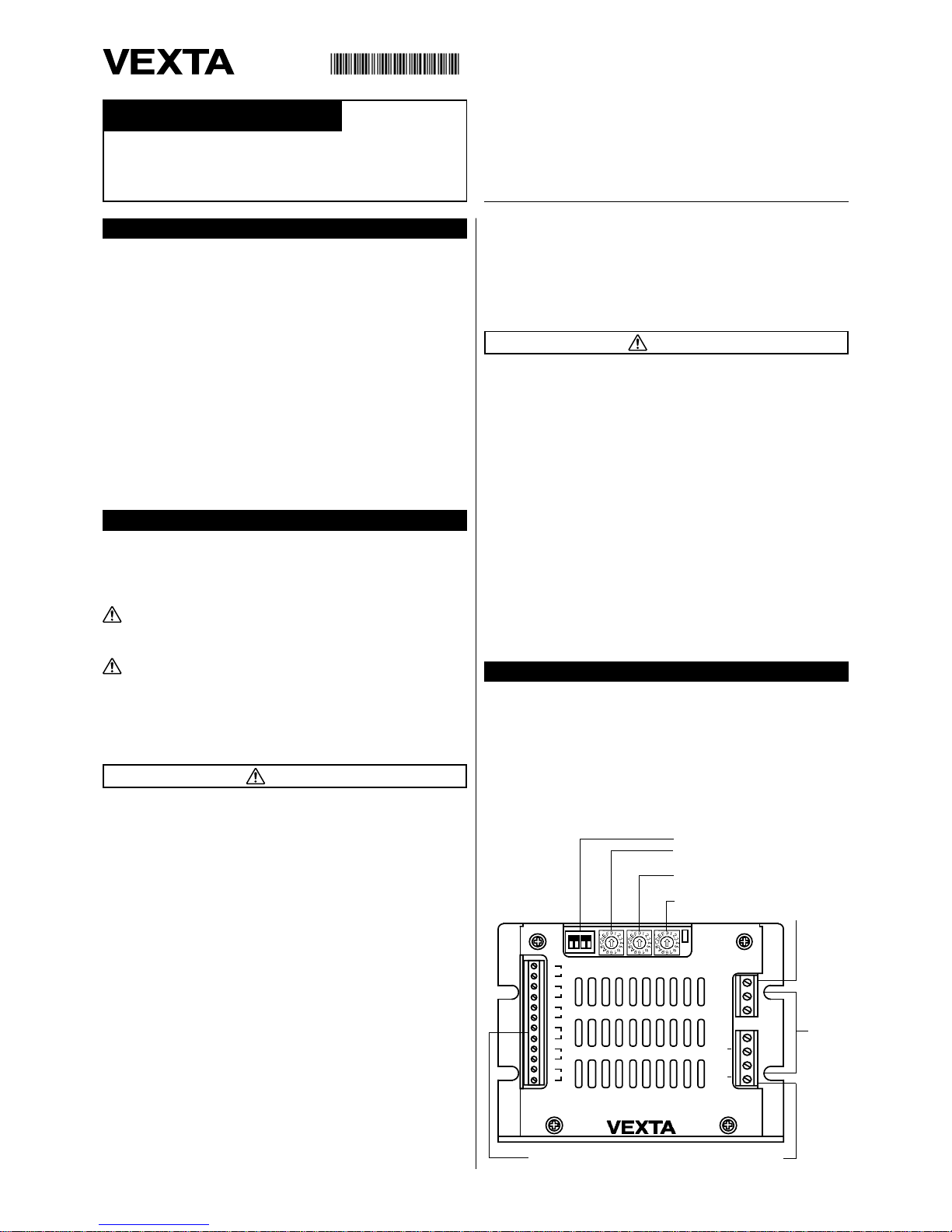
Names of parts
DC+
GND
A
A
B
B
FG
FUNCTION
STOP
POWER
1
4
RUN RES.
+
‑
STEP
+
‑
DIR.
+
‑
C.OFF
+
‑
RESET
+
‑
+
‑
ERR.
TIM.
2−PHASE DRIVER
D2D2043−S
2
3
Function selector switch (FUNCTION)
Motor standstill current
adjustment switch (STOP)
Motor running current
adjustment switch (RUN)
Step resolution switch (RES.)
I/O terminal block (TB1) Motor terminal block (TB3)
Mounting
cutouts
Power terminal block (TB2)
Safety precautions
The precautions described below are intended to prevent danger or
injury to the user and other personnel through safe, correct use of the
product. Use the product only after carefully reading and fully
understanding these instructions.
Warning
• Do not use the product in explosive or corrosive environments, in
the presence of flammable gases, locations subjected to splashing
water, or near combustibles.
• Assign qualified personnel the task of installing, wiring, operating/
controlling, inspecting and troubleshooting the product. Failure to
do so may result in fire or injury.
• Install the driver in an enclosure in order to prevent injury.
• Keep the driver’s input-power voltage within the specified range to
avoid fire.
• For the driver’s power supply, use a DC power supply with
reinforced insulation on its primary and secondary sides. Failure to
do so may result in electric shock.
• Connect the cables securely according to the wiring diagram in
order to prevent fire.
• Do not forcibly bend, pull or pinch the power cable or motor lead
wire. Doing so may result in fire.
• Turn off the driver power in the event of a power failure, or the motor
may suddenly start when the power is restored and may cause
injury or damage to equipment.
• If this product is used in an vertical application, be sure to provide a
measure for the position retention of moving parts. The motor loses
its holding torque when the power is turned off. Failure to provide
such a measure may cause the moving parts to fall, resulting in
injury or damage to the equipment.
Handling the product without observing the
instructions that accompany a “Warning” symbol may
result in serious injury or death.
Handling the product without observing the
instructions that accompany a “Caution” symbol may
result in injury or property damage.
Caution
Warning
Note
The items under this heading contain important
handling instructions that the user should observe to
ensure safe use of the product.
Page 2
2
Driver
Connection
Power source connection
The power-supply input voltage is 24VDC
-
40VDC±10%. Use a power source that can supply the following current capacity.
Applicable lead wire diameter: AWG26 ~ 16 (0.14 ~ 1.5mm2)
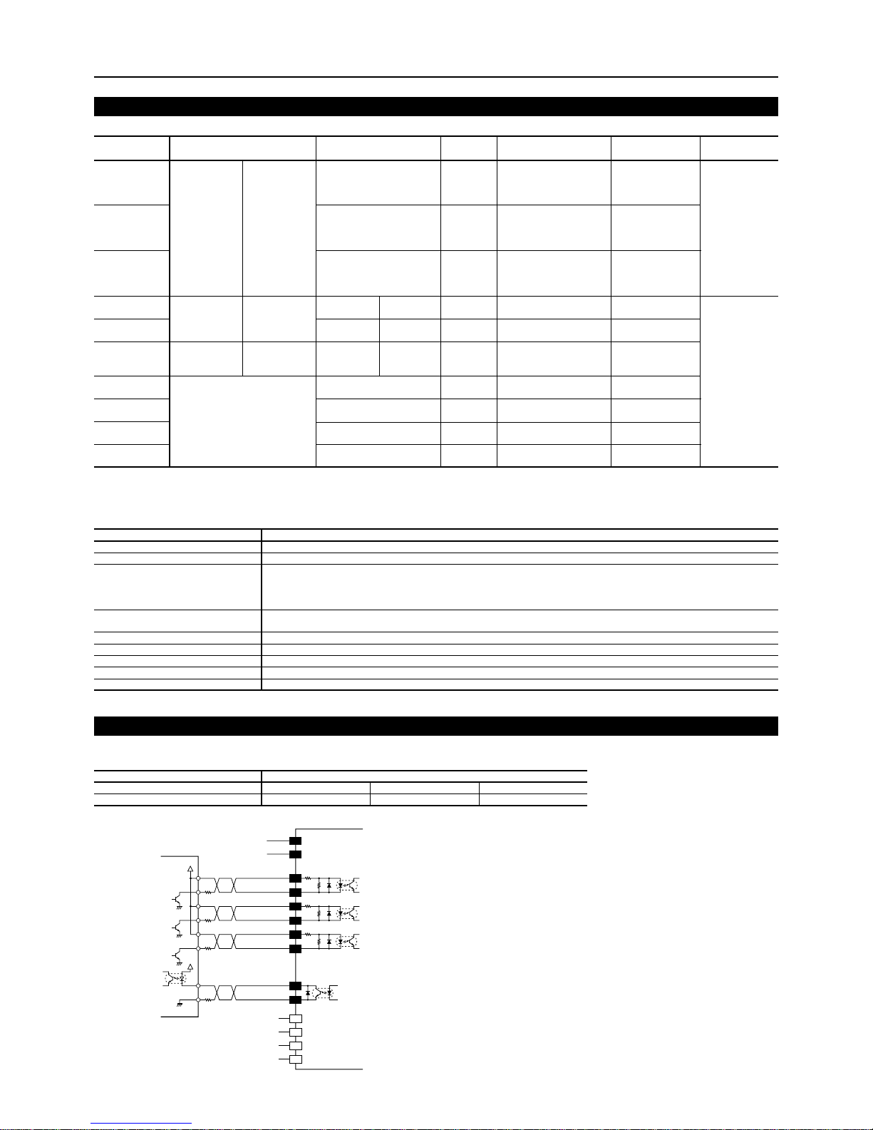
Note
• Make the input-signal voltage 5VDC minimum and 24VDC maximum. When
the input-signal voltage is 5VDC, external resistor R1 is not necessary. If the
input-signal voltage is greater than 5VDC, connect external resistor R1, to
restrict the input current as follows:
PLS: 7mA ~ 14mA
DIR./C.OFF: 10mA ~ 14mA
• Use an output-signal voltage of 5VDC minimum and 30VDC maximum, and
use output-signal current of 5mA max. If the output-signal current is greater
than 5mA, connect external resistor R2, to restrict the current to no more than
5mA.
TB3
1
2
3
4
+5V
330Ω
R
1
R
1
R
1
R
2
330Ω
330Ω
24VDC
-
40VDC
GND
TB2
TB1
1
2
+5V
Controller
STEP input
DIR. input
C.OFF input
TI M. output
1
3
5
7
2
4
6
8
+
-
+
+
-
+
-
1kΩ
1kΩ
1kΩ
8 lead wire type
1: Black/Orange
2: Green/Yellow
3: Red/Brown
4: Blue/White
Motor lead wire
4 lead wire type
1: Black
2: Green
3: Red
4: Blue
D2D2043-S
24VDC-40VDC±10% 5.3A
Microstep
Photocoupler input 5VDC, 14mA maximum, Input resistance 330Ω
Signal voltage Photocoupler ON: +4.2 ~ +6.0V
Photocoupler OFF: 0 ~ +0.7V
PLS, DIR, C.OFF, RESET
Photocoupler Open-collector output
Excitation monitor, Error: 30VDC maximum, 5mA maximum
Automatic current cutback, Overcurrent protection, Voltage-drop protection, Regenerative protection, Overheat protection
500
Natural ventilation
8.8 (0.25)
+32°F ~ +104°F (0°C ~ +40°C)
Driver model
Power input voltage
Excitation mode
Input signal
Output signal
Function
Maximum response pulse rate kHz
Driver cooling method
Mass oz (kg)
Ambient temperature range
• The input-power current supplied to the driver represents the maximum input value (which varies with pulse speed).
Example of connection
∗1 S: Bipolar series P: Bipolar parallel
∗2 Specifications for the PK26M
• Set the current motor standstill so that it will be a maximum of 50% of the motor’s running current.
Motor model
PK264-E2.0A
PK264M-E2.0A
PK264-E2.0B
PK264M-E2.0B
PK266-E2.0A
PK266M-E2.0A
PK266-E2.0B
PK266M-E2.0B
PK268-E2.0A
PK268M-E2.0A
PK268-E2.0B
PK268M-E2.0B
PK296-F4.5A
PK296-F4.5B
PK299-F4.5A
PK299-F4.5B
PK2913-F4.0A
PK2913-F4.0B
PV264-D2.8AA
PV264-D2.8BA
PV266-D2.8AA
PV266-D2.8BA
PV267-D2.8AA
PV267-D2.8BA
PV269-D2.8AA
PV269-D2.8BA
Rated current ∗1 A/phase
Motor running current adjustment
Maximum holding torque ∗1
oz-in (N·m)
75 (0.55)
170 (1.25)
270 (1.9)
150 (1.06)
248 (1.75)
312 (2.2)
440 (3.1)
Voltage ∗1
VDC
S: 4.0
P: 2.0
S: 5.1
P: 2.6
S: 6.4
P: 3.2
S: 2.8
P: 1.4
S: 3.9
P: 1.9
S: 5.3
P: 2.6
2.1
2.8
3.4
4.2
Resistance per phase ∗1
Ω/phase
S: 2.8
P: 0.7
S: 3.6
P: 0.9
S: 4.5
P: 1.13
S: 0.96
P: 0.24
S: 1.32
P: 0.33
S: 1.94
P: 0.49
0.73
1
1.2
1.49
Rotor inertia
oz-in
2
(kg·m2)
0.657 (120 × 10
-7
)
1.65 (300× 10
-7
)
2.63 (480× 10
-7
)
7.66 (1400 × 10
-7
)
14.8 (2700 × 10
-7
)
21.9 (4000 × 10
-7
)
1.54 (280 × 10
-7
)
2.47 (450 × 10
-7
)
3.12 (570 × 10
-7
)
4.93 (900 × 10
-7
)
Basic step angle
deg
1.8 [0.9] ∗2
1.8
2.8
Switch 2: ON
RUN: 4
P: 2.8
Switch 2: ON
RUN: 4
P: 4.38
Switch 2: ON
RUN: F
P: 4.38
Switch 2: ON
RUN: F
S: 1.4
Switch 2: OFF
RUN: A
S: 3.1
Switch 2: ON
RUN: 6
S: 2.8
Switch 2: ON
RUN: 4
S: 420 (3.0)
S: 850 (6.0)
S: 1320 (9.3)
P: 290 (2.1)
P: 600 (4.2)
P: 900 (6.4)
Main specifications
Motor (specifications of applicable motor)
Driver model
Motor type
Power-supply current capacity
PK26 type
2.7A minimum
D2D2043-S
PV26 type
3.2A minimum
PK29 type
5.3A minimum
Page 3

3
Connector configuration
Description
Frame GND
Power input
A phase output
A phase output
B phase output
B phase output
Pulse (CW pulse) input
Rotation direction (CCW pulse) input
ON: CW OFF: CCW
All windings off input
The excitation sequence is not reset.
Reset input
All windings off Excitation sequence reset, Error output reset
Excitation timing output
It is turned on when the excitation state indicates the excitation
home position.
Error output
In the following cases, it is turned on.
• When overcurrent protection function is active
• When voltage-drop protection function is active (18VDC maximum)
• When the regeneration protection function is active
Regenerative voltage: 56VDC minimum/Internal temperature of
driver: 75°C minimum
Terminal block
POWER
MOTOR
I/O
Terminal block No.
TB2
TB3
TB1
Pin No.
1
2
3
1
2
3
4
1
2
3
4
5
6
7
8
9
10
11
12
Input/output
Input
Output
Input
Output
Signal
FG
DC+
GND
A
A
B
B
STEP+
STEP
-
DIR.+
DIR.
C.OFF+
C.OFF
RESET+
RESET
-
TIM.+
TIM.
-
ERR+
ERR
-
Timing chart
∗1 When switching the power back again, wait at least 5sec.
∗2 When switching the C.OFF input to “ON,” the motor excitation ends and the holding-torque is removed.
∗3 The duration here may vary, depending on the motor’s size, running speed and the load’s moment of inertia.
The section indicates that the photocoupler diode is emitting light.
All windings off
1ms min.
1µs min.
100ms
min.
100ms min.
2-pulse input
*
2
*
3
CW
CW input
C.OFF input
CCW input
ON
OFF
ON
OFF
ON
OFF
Power input
CCW
Motor
*
1
1µs min.
All windings off
1ms min.
1-pulse input
*
2
100ms min.
100ms
min.
*
3
CW CW
0s min.
CCW
CW
STEP input
C.OFF input
DIR input
ON
OFF
ON
OFF
ON
OFF
Power input
CCW
Motor
*
1
Function selector switch description
Function
Motor standstill current selector
Motor running current selector
Pulse-input mode selector
All windings off
Switch: ON
2.26 ~ 4.38A/phase
2.26 ~ 4.38A/phase
1-pulse input mode
L level: excitation OFF
Switch: OFF
0 ~ 2.12A/phase
0 ~ 2.12A/phase
2-pulse input mode
H level: excitation OFF
Factory setting
OFF
OFF
ON
OFF
Switch No.
1
2
3
4
Page 4

4
Pulse waveform diagram
ON
OFF
STEP input
5µs
min.
5µs
min.
2µs
max.
2µs
max.
90%
10%
• When pulses are input, the motor rotates one step as the pulses
start (pulse fall).
• The voltage of the pulse signal is ON: +4.5 to +5.5V, OFF: 0 to
+0.7V. Input-pulse signals should have a pulse width exceeding
1µsec, pulse rise/fall below 1µsec, and a pulse duty of less than
50%.
Driving motor current
The D2D2043-S can drive motors with a rated current of up to
4.38A/phase. However, we recommend you follow the drive
conditions below in view of the rating of internal heat generation
(which affects product life).
(Running current)2 × X + (Standstill current)2 × (1 - X) < 7.5
X: Motor’s operating duty relative to operation time
Example) If the motor is used at an operating duty of 100% or
standstill current of 100%, the running current will be
2.12A/phase or less.
Setting
Step resolution
Use this function when you want to reduce vibration and noise, or to
change the motor speed or feed rate without changing the input pulse
speed.
Factory setting
Step resolution switch: 0
Motor current
Set the motor current in accordance with the motor’s rated current.
Factory setting
Motor running current adjustment switch: 0
Function selector switch
Switch 1: OFF
Switch 2: OFF
ORIENTAL MOTOR U.S.A. CORP.
Technical Support Line Tel:(800)468-3982
Available from 7:30 AM to 5:00 PM, P.S.T.
E-mail: techsupport@orientalmotor.com
www.orientalmotor.com
ORIENTAL MOTOR CO., LTD.
Headquarters Tokyo, Japan
Tel:(03)3835-0684 Fax:(03)3835-1890
• Please contact your nearest ORIENTAL MOTOR office for further information.
Printed on Recycled Paper
Setting value
0
1
2
3
4
5
6
7
8
9
A
B
C
D
E
F
Nos. of division
1
2
4
5
8
10
16
20
25
32
40
50
64
80
100
128
Step angle
1.8°
0.9°
0.45°
0.36°
0.225°
0.18°
0.1125°
0.09°
0.072°
0.05625°
0.045°
0.036°
0.028125°
0.0225°
0.018°
0.0140625°
• Set the current motor standstill so that it will be maximum 50% of
the motor’s running current.
Motor current setting (representative values)
Output current
setting
Motor current
adjustment switch
Setting
0
1
2
3
4
5
6
7
8
9
A
B
C
D
E
F
Switch 1:
OFF
0
0.14
0.28
0.42
0.57
0.71
0.85
0.99
1.13
1.27
1.41
1.56
1.70
1.84
1.98
2.12
Switch 1:
ON
2.26
2.40
2.55
2.69
2.83
2.97
3.11
3.25
3.39
3.54
3.68
3.82
3.96
4.10
4.24
4.38
Switch 2:
OFF
0
0.14
0.28
0.42
0.57
0.71
0.85
0.99
1.13
1.27
1.41
1.56
1.70
1.84
1.98
2.12
Switch 2:
ON
2.26
2.40
2.55
2.69
2.83
2.97
3.11
3.25
3.39
3.54
3.68
3.82
3.96
4.10
4.24
4.38
Function selector switch
Motor standstill
current value
A/phase
Motor running
current value
A/phase
=
 Loading...