

Page 1
HF-3027-3
© Copyright ORIENTAL MOTOR CO.,LTD. 1999
Thank you for purchasing ORIENTAL MOTOR products.
Please read this operating manual thoroughly before
installing and operating the fan, and always keep the
manual where it is readily accessible.
1. Precautions
1.1 Precautions for Installation
●Do not use in a place where there is flammable gas and/or corrosive gas.
●Fans for use only in equipment of protection class Ⅰ.
Lüfter zur Verwendung in Geräten der Schutzklasse Ⅰ.
●Connect the ground wire to the ground terminal inside the terminal box.
Das Erdungskabel wird an dem als Erde gekennzeichneten Pol im Anschluβkasten angeklemmt.
●When installing the fan into your equipment, ensure that the motor lead wires are fixed and do not move.
In addition, do not apply any pressure to these lead wires.
●Installation must be performed by a qualified installer.
1.2 Precautions for Operation
●Always turn off power to thermally protected fan before conducting checks or performing work on the fan.
These types of fans will restart automatically when fan temperature falls below a certain level.
●The enclosure temperature of this fan can exceed 70℃ (depending on operation conditions).
In case fan is accessible during operation, please attach the following warning label so that it is clearly visible. Warning label
●Do not touch the fan blades when the fan is in operation.
The use of the optional fingerguard is recommended to ensure protection.
Wegen der Verletzungsgefahr dürfen die Lüfterflügel bei Ventilatorbetrieb nicht berührt werden.
Der Gebrauch des als Sonderzubehör erhältlichen Fingerschutzes ist empfehlenswert, um erhöhte Sicherheit zu gewährleisten.
<Table of Contents>
1. Precautions
...........................................Page 1 4. Installation...........................................Page 2
2. Checking the Package Contents
...........Page 1 5. Noise Protection..................................Page 4
3. Connection
............................................Page 2 6. Overheat Protection............................Page 4
2. Checking the Package Contents
2.1 Checking the contents
Please make sure that the package contains all of the items listed below.
Contact your nearest ORIENTAL MOTOR office if any of these items are not included or are defective.
・Fan............................................................................................1 piece
・Variable resistor (with adjustment knob and dial plate).............1 set
・Operating manual (this manual)................................................1 piece
2.2 Checking the model name
This manual covers the products specified below.
Please make sure that the model, voltage, current as you ordered by the nameplate.
MRS18V2-B, MRS18V2-D
Fans are recognized by UL and certified by DEMKO.
・ Standards UL507, UL1917, CAN/CSA C22.2 No.113, EN60950
・ Installation Conditions for EN standards Installation categoryⅡ, Pollution degree 2, ClassⅠequipment
1
Varioflow Fans MRS18V2 type
OPERATING MANUAL
C
Page 2
2
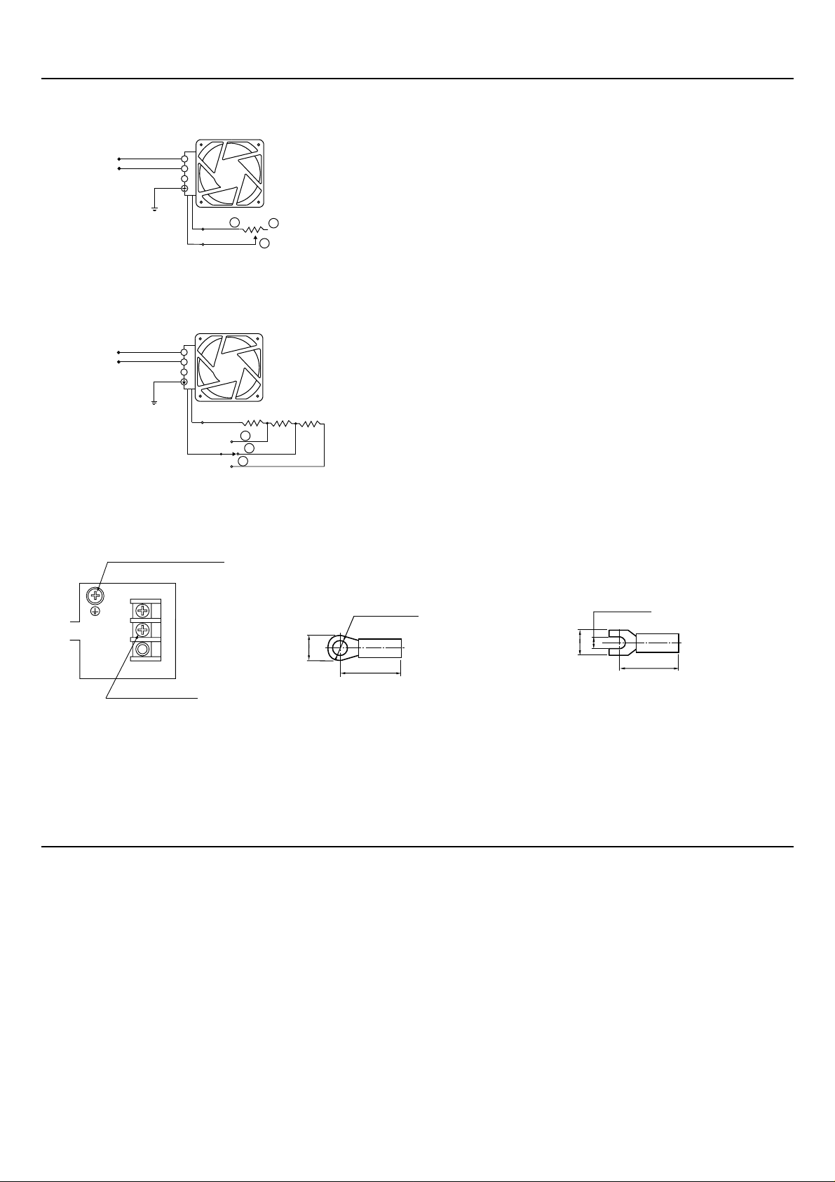
3. Connection
3.1 Connecting Diagrams
■ Using a variable resistor
①~③ indicate terminal numbers for variable resistors.
Turn the knob right to increase air flow-static pressure.
Variable resistor : 200kΩ 1/4W
with a linear resistance vs. angle curve
■ Using a fixed resistor
Fixed resistors that use relays or the like can also be switched.
R1+R2+R3=200kΩ (max.) 1/4W (min.)
3.2 Inside the terminal box
The recommended tightening torque for the terminal screws is 1.4N・m (14kgcm).
Recommended lead diameter
Power supply: AWG20 (0.5mm
2
), Ground: AWG18 (0.75mm2) min.
<Crimp style terminals that can be used>
●Round terminal type with insulation ●U-shaped terminal type with insulation
V1.25-4 AV1.25YS4A
(JAPAN SOLDERLESS TERMINAL MFG. CO., LTD.) (JAPAN SOLDERLESS TERMINAL MFG. CO., LTD.)
or other equivalent product or other equivalent product
4. Installation
Install the fan in locations that meet the following conditions.
・Indoors (the product is designed and manufactured to be mounted in a machine.)
・Ambient temperature −10℃(14°F)〜+60℃(140°F) (Non-freezing)
・Ambient humidity 0〜85% (Non-condensing)
・No explosive, flammable, and/or corrosive gas.
・No exposure to direct sunlight.
・No splashing of water, or exposure to dust or debris.
・No oil or grease, organic solvents, acid or alkaline chemicals.
・No continuous vibration or excessive shock.
・Insert a noise filter when there is a big noise source.
・Installation categoryⅡ, Pollution degree 2, ClassⅠequipment (EN standard).
Line
Ground
Blue
Lead for connecting
variable resistor
Line
1
2
Blue V.R.
1
2
3
1
2
Ground
Blue
Blue
Lead for connecting
variable resistor
Ground terminal (green)
M4×8
123
1
2
3
Terminal screws
2-M4×12
V.R.
R3
R2
R1
1
2
3
φ
4.3mm (min.)
8mm(max.)
9mm(min.)
4.3mm(min.)
8mm(max.)
9mm(min.)
Page 3

4.2 Soldering the Variable Resistor Terminals
Do the following to solder leads into place on the variable resistor terminals.
①Pass the leads through the terminal hole and wrap around two to three times.
②Solder the lead wire to the terminal.
③Cover the soldered area with a heat shrink tube.
4.3 Installing the Variable Resistor
①Insert the Variable resistor into the Mounting panel (insulation material) as shown in the figure below.
②Put on the scale plate and inner clip washer and fasten with the Nut. (Tightening torque: 0.45N・m [4.5kgcm] max.)
③Mount the Knob and fix it in place with the Stop screw M4. (Tightening torque: 0.4N・m [4kgcm] max.)
Note: Do not run a series of fans off a single Variable resistor. Circuit damage may result.
Example of Variable Resistor Installation
3
4.1 Mounting the fan
To mount the fan, drill holes in the machinery in which it will be installed referring to Panel-Cut-Out (see General Catalog)
and then fasten the fan with screws (these must be furnished by the user).
Use screws of M5 to install the fan.
The recommended tightening torque for mounting is 1.2N
・m (12 kgcm).
The direction of airflow is indicated by the AIRFLOW mark on the side of the fan frame.
The arrow points in the direction of the outlet. The rotation arrow indicates the direction of rotation.
Variable resistor unit
Soldered terminal
Lead wire
Heat shrink tube
Lead wire
Solder (wrap lead around
two to three times)
Enlargement of Circular Area
Variable resistor
Insulation sheet
20
Mounting panel
60
50
70
40
30
10
80
90
100
0
Scale plate
Crown washer
Nut
Knob
7.5±0.4
Stop screw
φ3
φ10
Panel Cut-Out drawing
Page 4

6. Overheat Protection
To prevent burning out the windings as a result of overheating, MRS18V2 type fans have been designed with a protector
explained below.
Thermal protector ; Automatic return type
Operating temperature of thermal protectors
Open : 120℃±5℃(248°F±9°F)
Close : 77℃±15℃(170°F±27°F)
4
5. Noise Protection
5.1 Protection from noise coming in from the power line
The MRS18V2 type do not have filters against power line noise.
When fans are used in noisy environments caused by high-output control and switching, the fan rpm will become unreliable.
Common causes of noise include high-output motors, solenoids, high-frequency power supplies and electric welders.
Commercial LC filters are very effective against external noise.
For a noise filter, we recommend the ORIENTAL MOTOR ZCB2203-11S (sold separately)
5.2 Preventing noise from being discharged externally from the power line
The MRS18V2 type use triacs for phase control, which can cause noise that affects other equipment.
A commercial LC filter is an effective way of reducing that noise.
●Characteristics, specifications and dimensions are subject to change without notice.
●Please contact your nearest ORIENTAL MOTOR office for further information.
ORIENTAL MOTOR CO.,LTD.
Headquarters
Tel:(03)3835-0684 Fax:(03)3835-1890
ORIENTAL MOTOR (EUROPA) GmbH
Headquarters and Düsseldorf Office
Tel:02131-95280 Fax:02131-952899
Munich Office
Tel:08131-59880 Fax:08131-598888
Hamburg Office
Tel:04076-910443 Fax:04076-910445
ORIENTAL MOTOR (UK) LTD.
Tel:01252-519809 Fax:01252-547086
ORIENTAL MOTOR (FRANCE) SARL
Tel:01 47 86 97 50 Fax:01 47 82 45 16
ORIENTAL MOTOR ITALIA s.r.l
Tel:02-3390541 Fax:02-33910033
ORIENTAL MOTOR U.S.A. CORP.
Los Angeles Office Tel:(310)784-8200 Fax:(310)325-1076
San Jose Office Tel:(408)358-6900 Fax:(408)358-8200
Chicago Office Tel:(847)240-2649 Fax:(847)240-2753
Cincinnati Office Tel:(513)563-2722 Fax:(513)956-3183
Austin Office Tel:(512)918-9438 Fax:(512)335-5983
New York Office Tel:(973)359-1100 Fax:(973)359-1090
Boston Office Tel:(781)848-2426 Fax:(781)848-2617
Atlanta Office Tel:(770)716-2800 Fax:(770)719-8515
Canada Office Tel:(905)502-5333 Fax:(905)502-5444
Technical Support Line:(800)468-3982
Available from 8:30 AM to 8:00 PM, Eastern Time
Using a variable resistor
Fan(MRS18V2)
Variable resistor
2
1
3
E
4
Noise filter
2
1
Circuit
breaker
SW1
Line
Using a variable resistor
Fan(MRS18V2)
Variable resistor
1
Noise filter
Circuit
breaker
SW1
4
E
Line
2
1
2
3
 Loading...