

Page 1
HM-60190-7
Closed Loop Stepping Motor and Driver Package
AR Series
DC power input Built-in Controller Type
USER MANUAL
Thank you for purchasing an Oriental Motor product.
This Operating Manual describes product handling procedures and safety precautions.
•Please read it thoroughly to ensure safe operation.
•Always keep the manual where it is readily available.
Page 2

1 Introduction
1 Introduction ................................................... 8
2 Operating Manuals for the AR Series .......... 9
3 Overview of the product ............................. 10
4 System conguration .................................. 12
5 Safety precautions ...................................... 13
6 Precautions for use ..................................... 16
7 General specications ................................ 18
8 CE Marking ................................................... 19
9 Preparation .................................................. 20
9.1 Checkingtheproduct................................... 20
9.2 Howtoidentifytheproductmodel............... 20
9.3 Combinationsofmotorsanddrivers............ 21
9.4 Namesandfunctionsofparts...................... 22
2 Installationand
connection
1 Installation ................................................... 26
1.1 Locationforinstallation................................ 26
1.2 Installingthemotor...................................... 26
1.3 Installingaload............................................ 27
1.4 Permissibleradialloadand
permissibleaxialload.................................. 28
1.5 Installingthedriver...................................... 29
1.6 Installingthebattery.................................... 30
1.7 Installingandwiringincompliancewith
EMCDirective.............................................. 30
2 Connection ................................................... 32
2.1 Connectionexample
(electromagneticbrakemotor)..................... 32
2.2 Groundingthemotoranddriver................... 36
2.3 Connectingthedatasetter.......................... 36
2.4 ConnectingtheRS-485communication
cable............................................................ 37
2.5 Connectingandchargingthebattery........... 38
3 Explanation of I/O signals .......................... 39
3.1 AssignmentofdirectI/O.............................. 39
Assignmenttotheinputterminals.....................39
Changingthelogiclevelsettingofinput
signals...............................................................40
Assignmenttotheoutputterminals...................41
3.2 AssignmentofnetworkI/O.......................... 43
Assignmentofinputsignals...............................43
Assignmenttotheoutputterminals...................45
3.3 Inputsignals................................................ 47
3.4 Outputsignals.............................................. 52
3.5 Sensorinput................................................ 56
3.6 Generalsignals(R0toR15)........................ 57
3 Operationtypeandsetting
1 Adjustment and setting .............................. 60
1.1 Resolution.................................................... 60
1.2 Operatingcurrent......................................... 61
1.3 Standstillcurrent.......................................... 61
1.4 Acceleration/decelerationrateand
acceleration/decelerationtime..................... 61
1.5 Smoothdrive............................................... 62
1.6 Speedlter.................................................. 62
1.7 Movingaveragelter................................... 63
1.8 Speederrorgain.......................................... 63
1.9 Controlmode............................................... 63
1.10 Positionloopgain,speedloopgain,
speedloopintegraltimeconstant................ 64
1.11 Absolute-positionbackupsystem................ 64
2 Operation ..................................................... 65
2.1 Positioningoperation................................... 66
Operationdata...................................................66
Startingmethodofpositioningoperation...........67
Operationfunction;Single-motion.....................71
Operationfunction;Linked-motionoperation.....72
Operationfunction;Linked-motionoperation2...73
Operationfunction;Push-motionoperation.......75
2.2 Return-to-homeoperation........................... 79
Additionalfunction.............................................79
Parametersrelatedtoreturn-to-home
operation............................................................80
Operationsequence..........................................81
Positionpreset...................................................86
2.3 Continuousoperation.................................. 86
Operationdata...................................................86
Startingmethodofcontinuousoperation...........87
Variablespeedoperation...................................89
2.4 Otheroperation............................................ 91
JOGoperation...................................................91
Testoperation....................................................92
Automaticreturnoperation................................92
Stopoperation...................................................93
Positioncoordinatemanagement......................93
Wrapfunction....................................................94
3 Operation data ............................................. 96
4 Parameter ..................................................... 97
4.1 Parameterlist.............................................. 97
4.2 I/Oparameter.............................................. 98
4.3 Motorparameter.......................................... 99
4.4 Operationparameter................................. 100
4.5 Return-to-homeparameter........................ 100
4.6 Alarm/warningparameter.......................... 101
4.7 Coordinationparameter............................. 101
4.8 Commonparameter................................... 101
4.9 I/Ofunctionparameter............................... 102
4.10 I/Ofunction[RS-485]parameter............... 103
4.11 Communicationparameter........................ 104
−2−
Page 3

4 MethodofcontrolviaI/O
1 Guidance .................................................... 106
2 Operation data ........................................... 108
3 Parameter ................................................... 109
3.1 Parameterlist............................................ 109
3.2 I/Oparameter............................................ 110
3.3 Motorparameter........................................ 110
3.4 Operationparameter..................................111
3.5 Return-to-homeparameter.........................111
3.6 Alarm/warningparameter.......................... 112
3.7 Coordinationparameter............................. 112
3.8 Commonparameter................................... 112
3.9 Communicationparameter........................ 112
3.10 I/Ofunctionparameter............................... 113
3.11 I/Ofunction[RS-485]parameter................ 114
4 Timing charts ............................................. 115
5 Methodofcontrolvia
ModbusRTU(RS-485
communication)
1 Guidance .................................................... 128
2 Communication specications ................ 130
3 Setting the switches .................................. 131
4 Setting the RS-485 communication ......... 133
5 Communication mode and
communication timing .............................. 134
5.1 Communicationmode................................ 134
5.2 Communicationtiming............................... 134
6 Message ..................................................... 135
6.1 Query......................................................... 135
6.2 Response.................................................. 137
7 Function code ............................................ 139
7.1 Readingfromaholdingregister(s)............ 139
7.2 Writingtoaholdingregister....................... 140
7.3 Diagnosis................................................... 141
7.4 Writingtomultipleholdingregisters........... 142
8 Register address list ................................. 143
8.1 Operationcommands................................ 143
8.2 Maintenancecommands........................... 144
8.3 Monitorcommands.................................... 145
8.4 ParameterR/Wcommands....................... 148
Operationdata.................................................148
Userparameters..............................................149
9 Group send ................................................ 158
10 Detection of communication errors ........ 160
10.1 Communicationerrors.............................. 160
10.2 Alarmsandwarnings................................ 160
11 Timing charts ............................................ 161
6 Methodofcontrolvia
industrialnetwork
1 Method of control via CC-Link
communication .......................................... 164
1.1 Guidance................................................... 164
1.2 Settingtheswitches................................... 167
1.3 Remoteregisterlist.................................... 168
1.4 AssignmentforremoteI/Oof6axes
connectionmode....................................... 168
AssignmentlistofremoteI/O..........................168
Input/outputofremoteI/O................................169
DetailsofremoteI/Oassignment....................170
1.5 AssignmentforremoteI/Oof12axes
connectionmode....................................... 171
AssignmentlistofremoteI/O..........................171
Input/outputofremoteI/O................................172
DetailsofremoteI/Oassignment....................174
2 Method of control via MECHATROLINK
communication .......................................... 176
2.1 Guidance................................................... 176
2.2 Settingtheswitches................................... 179
2.3 I/Oeldmapforthe
2.4 I/Oeldmapforthe
2.5 Communicationformat.............................. 182
RemoteI/Oinput.............................................182
RemoteI/Ooutput...........................................182
Remoteregisterinput......................................182
Remoteregisteroutput....................................183
3 Details of remote I/O ................................. 184
3.1 Inputsignalstothedriver.......................... 184
3.2 Outputsignalsfromthedriver................... 185
4 Command code list ................................... 186
4.1 Groupfunction........................................... 186
4.2 Maintenancecommand............................. 187
4.3 Monitorcommand...................................... 188
4.4 Operationdata........................................... 189
4.5 Userparameters........................................ 190
I/Oparameter..................................................190
Motorparameter..............................................191
Operationparameter.......................................191
Return-to-homeparameter..............................192
Alarm/warningparameter................................192
Coordinationparameter...................................192
Commonparameter.........................................193
I/Ofunctionparameter.....................................193
I/Ofunction[RS-485]parameter......................194
Communicationparameter..............................195
NETC01-M2
NETC01-M3
............. 180
............. 181
−3−
Page 4

7 Inspection,
troubleshootingand
remedialactions
1 Inspection .................................................. 198
2 Alarms and warnings ................................ 199
2.1 Alarms....................................................... 199
Alarmreset......................................................199
Alarmrecords..................................................199
Alarmlist..........................................................200
2.2 Warnings................................................... 204
Warningrecords..............................................204
Warninglist......................................................204
2.3 Communicationerrors............................... 205
Communicationerrorrecords..........................205
Communicationerrorlist..................................205
3 Troubleshooting and remedial actions ... 206
8 Appendix
1 Accessories (sold separately) .................. 208
Motorcable......................................................208
Datasetter.......................................................210
Communicationcableforthedatasetting
software...........................................................210
RS-485communicationcable..........................210
Batteryset.......................................................210
−4−
Page 5
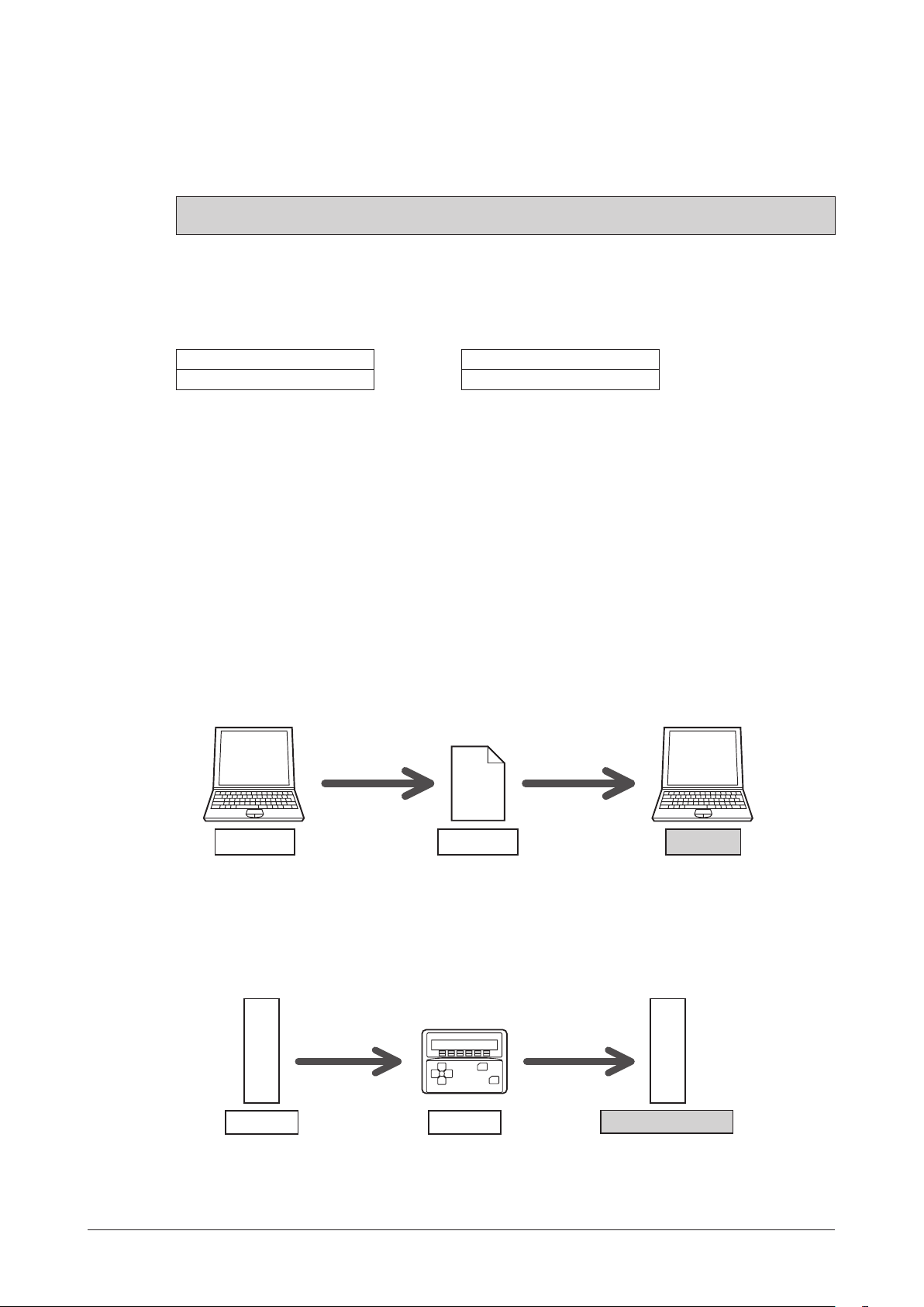
Specication Change of Driver
MEXE02 Version 3.00 or later MEXE02 older than Version 3.00
Driver after the specification change Driver before the specification change
Some specifications have been changed in this product. There are differences in data setting range, etc. between the
product after the change and before the change. For the driver before the specification change, contact your nearest
Oriental Motor sales office.
This manual describes contents of the driver which is after the specification change.
When using the driver which is before the specification change, take note of the following points.
1.Somesettingitemshavebeenchanged
Push current
Before the specification change
0 to 500 (1=0.1%) 0 to 1000 (1=0.1%)
NET-IN input function
The following input signals can be assigned in the product after the specification change.
•24: ALM-RST
•25: P-PRESET
•26: P-CLR
After the specification change
Pay attention to the data update
•When the data is set using the
MEXE02
If the
is older version than 3.00, the value after the specification change can not be set.
MEXE02
, use the
•When the following data passing is performed, the most recent value will not be effective
1) When the
using the older
If the data is opened by the older
2) When the
MEXE02
Latest value Latest value
OPX-2A
data which has set the value after the specification change is opened
MEXE02
than the Version 3.00
MEXE02
Saves the data Opens the data
than the Version 3.00, the data will be changed to the initial value.
Data file
data which has set the value after the specification change is downloaded
to the driver that is before the specification change
The value which is after the specification change will not be updated to the driver which is before the specification
change, and the value presently set is kept.
MEXE02
which software version is 3.00 or later
Initial value
OPX-2A
Uploads the data Downloads the data
Latest valueLatest value
Value before the change
−5−
Page 6

2.Theupperlimitofthealarmoutputhasbeenchanged
The maximum speed for push-motion operation has been changed. If push-motion operation is started after setting
higher speed than 30 r/min in the driver which is before the specification change, an operation data error alarm will
generate.
•Maximum speed for push-motion operation
Before the specification change
30 r/min 500 r/min
After the specification change
−6−
Page 7

1 Introduction
This part explains the composition of the operating manuals, the product overview, specifications and safety
standards as well as the name and function of each part and others.
Table of contents
1 Introduction ........................................ 8
2 Operating Manuals for the
AR Series ............................................. 9
3 Overview of the product .................. 10
4 System conguration ....................... 12
5 Safety precautions ........................... 13
6 Precautions for use .......................... 16
7 General specications ..................... 18
8 CE Marking ........................................ 19
9 Preparation ....................................... 20
9.1 Checking the product ............................20
9.2 How to identify the product model .........20
9.3 Combinations of motors and drivers .....21
9.4 Names and functions of parts .........
......2
2
Page 8

Introduction
1 Introduction
Before use
Only qualified personnel should work with the product.
Use the product correctly after thoroughly reading the section "5 Safety precautions" on p.13.
The product described in this manual has been designed and manufactured for use in general industrial equipment.
Do not use for any other purpose. Oriental Motor Co., Ltd. is not responsible for any damage caused through failure
to observe this warn
Hazardous substances
The products do not contain the substances exceeding the restriction values of RoHS Directive (2011/65/EU).
Notation rules
The following term is used in explanation of this manual.
Term Description
Master controller
ing.
This is a generic name for a programmable controller, master module,
pulse generator and so on.
−8−
1Introduction
Page 9

Operating Manuals for the AR Series
2 Operating Manuals for the AR Series
Operating manuals for the AR Series FLEX DC power input built-in controller type are listed below.
The "USER MANUAL" does not come with the product. For details, contact your nearest Oriental Motor sales office
or download from Oriental Motor website download page.
After reading these manuals, keep them in a convenient place so that you can reference them at any time.
Applicable product Type of operating manual Description of operating manual
Motor
OPERATING MANUAL
(Supplied with motor)
AR
Series FLEX
DC power input
Built-in controller type
Data setting software
MEXE02
Data setter
Network converter
OPX-2A
Driver
OPERATING MANUAL
(Supplied with driver)
USER MANUAL (this document)
OPERATING MANUAL
OPERATING MANUAL
CC-Link compatible
NETC01-CC
USER MANUAL
MECHATROLINK-Ⅱ compatible
NETC01-M2
USER MANUAL
MECHATROLINK-Ⅲ compatible
NETC01-M3
USER MANUAL
EtherCAT compatible
NETC01-ECT
OPERATING MANUAL
With regard to the information required to be certified under the UL Standard, refer to the "APPENDIX UL Standards
for AR Series DC power input type" (the paper is supplied with the product).
This manual explains the functions as well as the
installation method and others for the motor.
This manual explains the functions as well as the
installation method and others for t
This manual explains the functions, installation/
connection method and data setting method as well
as the operating method and others for the motor and
driver.
This manual explains how to set data using the
accessory
This manual explains the functions and installation/
connection method as well as data setting method and
o
thers for the accessory
This manual explains the functions and installation/
connection method as well as the operating method
for the network converter.
MEXE02
.
OPX-2A
ver.
he dri
(sold separately).
1Introduction
−9−
Page 10

Overview of the product
3 Overview of the product
This product is a motor and driver package product consisting of a high-efficiency stepping motor equipped with a
rotor position detection sensor, and a driver with built-in controller function.
This product can be controlled via I/O, Modbus RTU (RS-485 communication) or industrial network communication
using the network converter.
The operation data and parameters can be set using the accessory
485 communication.
Main features
•Introducing closed loop control
The AR Series can continue its operation even upon encountering quick acceleration or an abrupt change in load.
Monitoring the speed and amount of rotation while the motor is running, the AR Series performs the closed-loop
control under overload and similar conditions to continue its operation at the peak torque.
hree operating patterns
•T
You can perform positioning operation, return-to-home operation and continuous operation.
Up to 64 operation data points can be set, and multi-point positioning is also possible.
•Compatible with Modbus RTU (RS-485 communication)
You can set operation data and parameters or issue operation start/stop commands from the master controller.
Up to 31 drivers can be connected to one master.
OPX-2A
(sold separately) or
MEXE02
or via RS-
,
•Absolute-position backup system
When connecting an accessory battery set
backup system. Positions will be retained in the event of a power outage or after turning off the driver power.
BAT01B
(sold separately), this product can be used in the absolute-position
•Automatic control of the electromagnetic brake
This driver controls the electromagnetic brake automatically. The control signal input or the troublesome ladder logic
design can be saved.
•Energy-saving
Motor and driver losses have been substantially reduced to achieve low heat generation and save energy.
Since the motor and driver generate much less heat, they can now be operated for longer hours at high speed, which
was not possible with conventional motors/drivers.
•Alarm and warning functions
The driver provides alarms that are designed to protect the driver from overheating, poor connection, error in
operation, etc. (protective functions), as well as warnings that are output before the corresponding alarms generate
(warning functions).
Accessories
The operation data and parameters can be set using the accessory
485 communication. Provide the
OPX-2A
MEXE02
or
as necessary.
OPX-2A
(sold separately) or
MEXE02
, or via RS-
Related products
The AR Series FLEX DC power input built-in controller type can be used via various network when connecting to a
network converter.
−10−
Network converter Supported network
NETC01-CC
NETC01-M2
NETC01-M3
NETC01-ECT
CC-Link communication
MECHATROLINK-Ⅱ communication
MECHATROLINK-Ⅲ communication
EtherCAT communication
1Introduction
Page 11

Function list
Main functions
Overview of the product
Return-to-home operation
[Setting by parameters]
Motor operation
[Setting by operation data
and parameters]
Other operations
[Setting by parameters]
Support functions
• 2-sensor mode
• 3-sensor mode
• Push-mode
• Data setting mode (Position preset)
• Positioning operation
Operation function
Single-motion operation
Linked-motion operation
Linked-motion operation 2
Push-motion
• Continuous operation
• JOG operation
• Automatic return operation
Starting method
Data number selecting operation
+
Direct positioning operation
Sequential positioning operation
[Setting by parameters]
External interface
Data setter
RS-485 communication
• Protective function
Alarm detection
Warning detection
• I/O function
Input function selection
Output function selection
Input logic level setting
• Coordination setting
Resolution (Electronic gear)
Wrap function
Motor rotation direction
• Monitor function
• Operation data setting
• Parameter setting
• Operation start
• Operation data setting
• Parameter setting
• Return-to-home function
Home position offset
External sensor signal detection
• Stop operation
STOP input action
Hardware overtravel
Software overtravel
• Motor function setting
Operating current
Standstill current
Speed filter
Moving average filter
• Data storing
• Download/Upload
• Data initialization
• Test function
Test operation
Teaching
I/O test
• Monitor function
• Maintenance function
1Introduction
−11−
Page 12
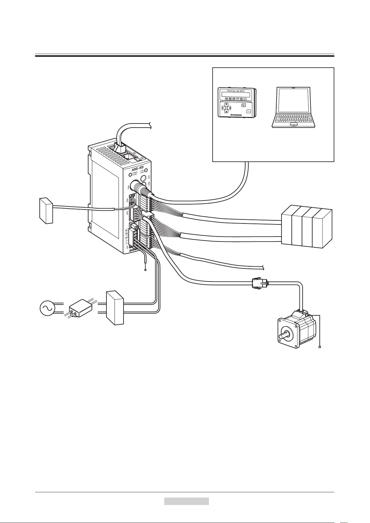
System configuration
4 System conguration
Connect to
CN4
Battery
This battery is an accessory
BAT01B (sold separately).
Connect this battery if you
want to operate the driver
in the absolute system.
AC power
supply
Noise filter
Use a noise filter to
eliminate noise.
It has the effect of
reducing noise generated
from the power supply
and driver.
Connect to CN6 or CN7
FG
24 VDC
or
48 VDC
GND
Connect to CN1
DC power
supply
Master controller
Connect when controlling
the system via RS-485
communication.
Connect to CN3
Output signals: Connect to CN9
Input signals: Connect to CN8
Connect to CN2
Cable for motor
This cable is used to connect
the motor and driver.
OPX-2A
(sold separately)
Connect to CN5
PC in which the MEXE02
has been installed
Or
The PC must be supplied by the
customer. Use the communication
cable for the data setting software
CC05IF-USB when connecting
the PC and driver.
Master controller
Sensor
Motor
PE
−12−
1Introduction
Page 13

5 Safety precautions
The precautions described below are intended to prevent danger or injury to the user and other personnel through safe,
correct use of the product. Use the product only after carefully reading and fully understanding these instructions.
Handling the product without observing the instructions that accompany a "Warning"
symbol may result in serious injury or death.
Handling the product without observing the instructions that accompany a “Caution”
symbol may result in injury or property damage.
The items under this heading contain important handling instructions that the user should
observe to ensure safe use of the product.
General
•Do not use the product in explosive or corrosive environments, in the presence of flammable gases, locations
subjected to splashing water, or near combustibles. Doing so may result in fire or injury.
•Assign qualified personnel the task of installing, wiring, operating/controlling, inspecting and troubleshooting the
product. Failure to do so may result in fire, injury or damage to equipment.
ke measures to keep the moving parts in position for vertical operations such as elevator applications. The motor
Ta
•
loses holding torque when the power is shut off, allowing the moving parts to fall and possibly cause injury or
damage to equipment.
•The brake mechanism of an electromagnetic brake motor is used to keep the moving part and motor in position. Do
not use it as a deceleration/safety b
•When the driver generates an alarm (any of the driver's protective functions is triggered), take measures to hold
the moving part in place since the motor stops and loses its holding torque. Failure to do so may result in injury or
damage to equipment.
•When the driver generates an alarm (any of the driver's protective functions is t
then clear the protection function. Continuing the operation without removing the cause of the problem may cause
malfunction of the motor and driver, leading to injury or damage to equipment.
rake
. Doing so may result in injury or damage to the equipment.
Safety precautions
riggered), first remove
the cause and
Installation
•Install the motor and driver in the enclosure in order to prevent injury.
Connection
•Keep the driver's input power voltage within the specified range. Failure to do so may result in fire.
•For the driver’s power supply, use a DC power supply with reinforced insulation on its primary and secondary
sides. Failure to do so may result in electric shock.
•Connect the cables securely according to the wiring diagram. Failure to do so may result in fire.
•Do not forcibly bend, pull or pinch the cable. Doing so may cause fire.
•Turn off the power to both the PC and
electric shock.
drive
r before connecting your PC to the driver. Failure to do so may cause
Operation
•Turn off the driver power in the event of a power failure. Or the motor may suddenly start when the power is
restored and may cause injury or damage to equipment.
•Do not turn the FREE input to ON while the motor is operating. The motor will stop and lose its holding power.
Doing so may result in
injury or damage to equipment.
Repair, disassembly and modification
•Do not disassemble or modify the motor and driver. Doing so may cause injury. Refer all such internal inspections
and repairs to the branch or sales office from which you purchased the product.
1Introduction
−13−
Page 14

Safety precautions
General
Transportation
Installation
Connection
•Do not use the motor and driver beyond its specifications. Doing so may result in injury or damage to equipment.
•Keep your fingers and objects out of the openings in the motor and driver. Failure to do so may result in fire or
injury.
•Do not touch the motor and driver during operation or immediately after stopping. The surface is hot and may
cause a skin burn(s).
BA
•Do not use other batterie
injury or damage to equipment.
•Do not carry the motor by holding the motor output shaft or motor cable. Doing so may cause injury.
•Provide a cover over the rotating parts (output shaft) of the motor. Failure to do so may result in injury.
•Do not leave anything around the motor and driver that wo
to equipment.
•The power supply connector (CN1), data edit connector (CN3) and RS-485 communication connector (CN6/
CN7) of the driver are not electrically insulated. When grounding the positive terminal of the power supply, do not
connect any equipment (PC, etc.) whose negative terminal is grounded. Doing so may cause the drive
equipment to short, damaging both.
•When connecting, check the silk screen of the driver and pay attention to the polarity of the power supply. Reversepolarity connection may cause damage to the driver. The power-supply circuit and the RS-485 communication
circuit are not insulated. Reverse-polarity connection may cause damage to the driver.
s than the accessory dedicated battery
T01B
(sold separately). Doing so may result in
uld obstruct ventilation. Doing so may result in damage
r and these
Operation
•Use a motor and driver only in the specified combination. An incorrect combination may cause a fire.
•Do not touch the rotating part (output shaft) during operation. Doing so may cause injury.
•Provide an emergency stop device or emergency stop circuit external to the equipment so that the entire equipment
will operate safely in the event of a system failure or malfunction. Failure to do so may result in injury.
•For the power s
and secondary sides. Failure to do so may result in electric shock.
•Before supplying power to the driver, turn all input signals to the driver OFF. Otherwise, the motor may start
suddenly at power ON and cause injury or damage to equipment.
•Before moving the motor directly with the hands, confirm t
result in injury.
•Immediately when trouble has occurred, stop running and turn off the driver power. Failure to do so may result in
fire or injury.
upply to the electromagnetic brake
, use a DC power supply with reinforced insulation on its primary
hat the FREE input turns ON. Fa
ilure to do so may
Maintenance and inspection
•To prevent the risk of electric shock, do not touch the terminals while performing the insulation resistance test or
dielectric strength test.
Disposal
•To dispose of the motor and driver, disassemble it into parts and components as much as possible and dispose of
individual parts/components as industrial waste.
−14−
1Introduction
Page 15

Safety precautions
Handling the battery
Be sure to observe the following instructions when using the accessory battery (sold separately). Handling the battery
without observing the instructions may cause the liquid leakage, heat generation and explosion, etc., which may result
in injury or damage to equipment.
•Do not heat the battery or throw it into a fire.
•Never short-circuit the battery or connect the positive and negative terminals in reverse.
•When carrying/storing the battery, do not place it together with metal necklaces, hairpins, coins, keys or other
conductive objects. When storing the battery, store it away from direct sunlight in a place not subject to high
temperature or high humidity.
•D
o not disassemble or modify the battery.
•D
o not apply solder directly to the battery.
•Use a dedicated driver to charge the battery.
•The battery has a vent structure for the release of internal gas. Do not apply a strong force to the battery, since it
may cause this structure to deform.
•When installing the battery into the machine, never place it inside a sealed structure. The battery sometimes
g
enerates gas, which, if trapped, may cause a burst or an explosion due to ignition.
•The battery contains an alkali solution. If the alkali solution comes in contact with the skin or clothes, flush the area
thoroughly with clean water. If the alkali solution gets into the eyes, do not rub. Flush the eyes thoroughly with
clean water and seek immediate medical attention.
•Do not use the battery if
•D
o not immerse the battery in water or seawater, nor allow it to become wet. Doing so may cause the battery to
generate heat or rust.
•Do not scratch the battery and battery cable. A scratched battery easily causes shorting, resulting in leakage, heat
generation or bursting.
•The battery is connected to the primary circuit, so d
•Do not forcibly bend, pull or pinch the cable. Also, do not bend and flex the cable repeatedly.
•Do not make a continuous vibration or excessive impact.
Note
•Always charge the battery connecting to the driver before use. Refer to p.38 for charging method.
•Nickel-metal-hydride cell is used in this battery. Disposal of the used batteries is
subject to each country's regulations on environmental control. Contact your nearest
Oriental Motor office if you have any questions.
there is leakage, discoloration, deformation or another abnormality.
o not touch the battery while the pow
er is on.
1Introduction
−15−
Page 16

Precautions for use
6 Precautions for use
This section covers limitations and requirements the user should consider when using the product.
•Always use the cable (supplied or accessory) to connect the motor and driver.
Be sure to use the cable (supplied or accessory) to connect the motor and driver.
In the following condition, an appropriate accessory cable must be purchased separately. Refer to p.208 for details.
•If a flexible cable is to be used.
•I
f a cable of 3 m (9.8 ft.) or longer is to be used.
•If a motor and driver package without a cable was purchased.
•Perform the insulation resistance test or dielectric strength test separately on the motor and the
driver.
Performing the insulation resistance test or dielectric strength test with the motor and driver connected may result in
damage to the product.
•Do not apply a radial load and axial load in excess of the specified permissible limit
Operating the motor under an excessive radial load or axial load may damage the motor bearings (ball bearings). Be
sure to operate the motor within the specified permissible limit of radial load and axial load. Refer to p.28 for details.
•Use the motor in conditions where its surface temperature will not exceed 100 °C (212 °F).
The driver has an overheat protection function, but the motor has no such feature. The motor surface temperature may
exceed 100 °C (212 °F) under certain conditions (ambient temperature, operating speed, duty cycle, etc.). To prevent
the motor bearings (ball bearings) from reaching its usable life quickly, use the motor in conditions where the surface
temperature will not exceed 100 °C (212 °F).
Use the gea
prevent deterioration of grease and parts in the gear case.
If the motor is to be operated continuously, install the motor in a location where heat dissipation capacity equivalent
to a level achieved with a heat sink [made of aluminum, 250×250×6 mm (9.84×9.84×0.24 in.)] is ensured.
red type motor in a condition where the gear case temperature does not ex
ceed 70 °C (158 °F), in order to
•Holding torque at standstill
The motor holding torque is reduced by the current cutback function of the driver at motor standstill. When selecting
a motor for your application, consider the fact that the holding torque will be reduced at motor standstill.
•Do not use the electromagnetic brake to reduce speed or as a safety brake.
Do not use the electromagnetic brake as a means to decelerate and stop the motor. The brake hub of the
electromagnetic brake will wear significantly and the braking force will drop.
Since the power off activated type electromagnetic brake is equipped, it helps maintain the position of the load when
the power is cut off, but this brake cannot securely hold the load in place. Accordingly, do not use the electromagnetic
brake as a safety brake.
To use the electromagnetic brake to ho
ld the load in place, do so after the motor has stopped.
•Double shaft type motor
Do not apply load torque, radial load or axial load to the output shaft on the opposite side of the motor output shaft.
•Preventing electrical noise
See "1.7 Installing and wiring in compliance with EMC Directive" on p.30 for measures with regard to noise.
•Peak torque of geared type motor
Always operate the geared type motor under a load not exceeding the peak torque. If the load exceeds the peak torque,
the gear will be damaged.
•Grease of geared type motor
On rare occasions, a small amount of grease may ooze out from the geared type motor. If there is concern over
possible environmental damage resulting from the leakage of grease, check for grease stains during regular
inspections. Alternatively, install an oil pan or other dev
leakage may lead to problems in the customer’s equipment or products.
ice to prevent leakage from causing further damage. Oil
−16−
1Introduction
Page 17

Precautions for use
•Rotation direction of the gear output shaft
The relationship between the rotation direction of the motor shaft and that of the gear output shaft changes as follows,
depending on the gear type and gear ratio.
Type of gear Gear ratio
TH
geared
PS
geared
PN
geared
Harmonic geared All gear ratios Opposite direction
3.6, 7.2, 10 Same direction
20, 30 Opposite direction
All gear ratios Same direction
(relative to the motor rotation direction)
Rotation direction
•Do not perform push-motion operation with geared types.
Doing so may cause damage to the motor or gear part.
•Saving data to the non-volatile memory
Do not turn off the power supply while writing the data to the non-volatile memory and 5 seconds after the
completion of writing the data. Doing so may abort writing the data and cause a EEPROM error alarm to generate.
The non-volatile memory can be rewritten approximately 100,000 times.
•Motor excitation at power ON
The motor is excited when the power is on. If the motor is required to be in non-excitation status when turning on the
power, assign the C-ON input to the direct I/O or network I/O.
•Overvoltage alarm by regeneration energy
The overvoltage alarm will generate depending on the operating condition. When an alarm is generated, review the
operating conditions.
•Note on connecting a power supply whose positive terminal is grounded
The power supply connector (CN1), data edit connector (CN3) and RS-485 communication connector (CN6/CN7)
of the driver are not electrically insulated. When grounding the positive terminal of the power supply, do not connect
any equipment (PC, etc.) whose negative terminal is grounded. Doing so may cause the driver and these equipment to
short, damaging both. Use the
OPX-2A
to set data, etc.
1Introduction
−17−
Page 18

General specifications
7 General specications
Motor Driver
IP65 (Excluding the motor mounting
surface and connectors)
Degree of protection
Ambient
temperature
Operation
environment
Storage
environment
Shipping
en
vironment
Insulation resistance
Dielectric strength
*1 When installing a motor to a heat sink of a capacity at least equivalent to an aluminum plate [100×100 mm
(3.94×3.94 in.), thickness 6 mm (0.24 in.)].
*2 0.5 kVAC for the
Humidity 85% or less
A
ltitude Up to 1000 m (3300 ft.) above sea level
Surrounding
atmosphere
Ambient
temperature
Humidity 85% or less (non-condensing)
Altitude Up to 3000 m (10000 ft.) above sea level
Surrounding
atmosphere
mbient
A
temperature
Humidity 85% or less (non-condensing)
Altitude Up to 3000 m (10000 ft.) above sea level
Surrounding
atmosphere
ARM14, ARM15, ARM24
IP20 (Double shaft type, models
including "S" in the motor identification
of motor name.)
−
10 to +50 °C (+14 to +122 °F)
(non-freezing)
Harmonic geared type: 0 to +40 °C
(+32 to +104 °F) (non-freezing)
No corrosive gas, dust, water or oil
−
20 to +60 °C (−4 to +140 °F)
(non-freezing)
No corrosive gas, dust, water or oil
−
20 to +60 °C (−4 to +140 °F)
(non-freezing)
No corrosive gas, dust, water or oil
100 MΩ or more when 500 VDC megger
is applied between the following places:
· Case - Motor windings and sensor
windings
·
Case - Electromagnetic brake windings
Sufficient to withstand 1.0 kVAC at
50 Hz or 60 Hz applied between the
following places for 1 minute:
· Case - Motor windings and sensor
windings
· Case - Electromagnetic brake
windings"
1
∗
(non-condensing)
ARM26
and
types
IP10
0 to +50 °C (+32 to +122 °F)
(non-freezing)
1
∗
−
25 to +70 °C (−13 to +158 °F)
(non-freezing)
−
25 to +70 °C (−13 to +158 °F)
(non-freezing)
100 MΩ or more when 500 VDC megger
is applied between the following places:
· FG terminal - Power supply terminal
2
∗
Sufficient to withstand 500 VAC at
50 Hz o
r 60 Hz applied betwe
following places for 1 minute:
· FG terminal - Power supply terminal
en the
−18−
1Introduction
Page 19

8 CE Marking
Low Voltage Directives
Because the input power supply voltage of this product is 24 VDC/48 VDC, it is not subject to the Low Voltage
Directive but install and connect this product as follows.
This product is designed and manufactured to be installed within another device. Install the product in an enclosure.
For the driver power supply, use a DC power supply with reinforced insulation on its primary and secondary sid
EMC Directive
This product has received EMC compliance under the conditions specified in "Example of motor and driver
installation and wiring" on p.31. Since the compliance of the final machinery with the EMC Directive will depend on
such factors as the configuration, wiring, layout and risk involved in the control-system equipment and electrical
parts, it therefore must be verified through EMC measures by th
Applicable Standards
EMI
EMS
EN 61000-6-4
EN 61800-3
EN 55011 group 1 class A
EN 61000-6-2
EN 61800-3
CE Marking
es.
e customer of the machinery.
1Introduction
−19−
Page 20

Preparation
AR 2 4 S A K D - H 50 - 3
9 Preparation
This chapter explains the items you should check, as well as the name and function of each part.
9.1 Checking the product
Verify that the items listed below are included. Report any missing or damaged items to the branch or sales office
from which you purchased the product.
Verify the model number of the purchased product against the number shown on the package label.
Check the model number of the motor and driver against
motor and driver combinations are shown on p.22.
•Motor .................................................1 unit
•Parallel key ........................................1 pc. (Supplied with geared types; except for the
•Cable for motor .................................1 pc. (Supplied with a motor and driver package)
•Cable for electromag
•Driver ................................................1 unit
•CN1 connector ..................................1 pc. (for power supply input terminals; 5 pins)
•CN5 connector ..................................1 pc. (for sensor signals; 5 pins)
•CN8 connector ..................................1 pc. (for inpu
N9 connector ..................................1 pc. (for output signals; 7 pins)
•C
•Motor OPERATING MANUAL .......1 copy
•Driver OPERATING MANUAL .......1 copy
netic brake
the number show
AR66TH
.......1 pc. (Supplied with an electromagnetic brake motor and driver package)
)
t signals; 9 pins)
n on the nameplate. Model names for
AR24, AR46TH
and
9.2 How to identify the product model
Motor size 1: 20 mm (0.79 in.)
2: 28 mm (1.10 in.) [30 mm (1.18 in.) for Harmonic geared type]
4: 42 mm (1.65 in.)
6: 60 mm (2.36 in.)
9: 85 mm (3.35 in.) [90 mm (3.54 in) for geared types]
Series name AR Series
* The model name is "7" for the gear ratio "7.2" of the PS geared type.
Gear ratio
T: TH geared type㻌 H: Harmonic geared type
PS: PS geared type㻌 Blank: Standard type
N: PN geared type
Driver type D: Built-in Controller Type
Power input K: 24 VDC/48 VDC
Motor type A: Single shaft
B: Double shaft
M: With electromagnetic brake
Motor identification
Motor length
Number: Length of supplied connection cable (m)
None: Without connection cable
∗
−20−
1Introduction
Page 21

9.3 Combinations of motors and drivers
indicates A (single shaft), B (double shaft) or M (with electromagnetic brake).
••
AR14S
For
For geared type, indicates A (single shaft) or M (with electromagnetic brake).
•When a connection cable is included, in the model names indicates a number (-1, -2, -3) representing the cable
length.
in the model names indicates a number representi
••
Standard type
TH
geared type
PS
geared type
PN
geared type
Harmonic geared type
AR15S
and
, indicates A (single shaft) or B (double shaft).
ng the gear ratio.
Type Model Motor model Driver model
AR14SKD
AR15SKD
AR24SKD
AR26SKD
AR46SKD
AR46KD
AR66SKD
AR66KD
AR69SKD
AR69KD
AR98SKD
AR98KD
AR24SKD-T
AR46SKD-T
AR46KD-T
AR66SKD-T
AR66KD-T
AR98SKD-T
AR98KD-T
AR24SAKD-PS
AR46SKD-PS
AR46KD-PS
AR66SKD-PS
AR66KD-PS
AR98SKD-PS
AR98KD-PS
AR24SAKD-N
AR46SKD-N
AR46KD-N
AR66SKD-N
AR66KD-N
AR98SKD-N
AR98KD-N
AR24SKD-H
AR46SKD-H
AR46KD-H
AR66SKD-H
AR66KD-H
AR98SKD-H
AR98KD-H
ARM14SK
ARM15SK
ARM24SK
ARM26SK
ARM46SK
ARM46K
ARM66SK
ARM66K
ARM69SK
ARM69K
ARM98SK
ARM98K
ARM24SK-T
ARM46SK-T
ARM46K-T
ARM66SK-T
ARM66K-T
ARM98SK-T
ARM98K-T
ARM24SAK-PS
ARM46SK-PS
ARM46K-PS
ARM66SK-PS
ARM66K-PS
ARM98SK-PS
ARM98K-PS
ARM24SAK-N
ARM46SK-N
ARM46K-N
ARM66SK-N
ARM66K-N
ARM98SK-N
ARM98K-N
ARM24SK-H
ARM46SK-H
ARM46K-H
ARM66SK-H
ARM66K-H
ARM98SK-H
ARM98K-H
Preparation
ARD-KD
ARD-KD
ARD-KD
ARD-KD
ARD-KD
1Introduction
−21−
Page 22
Preparation
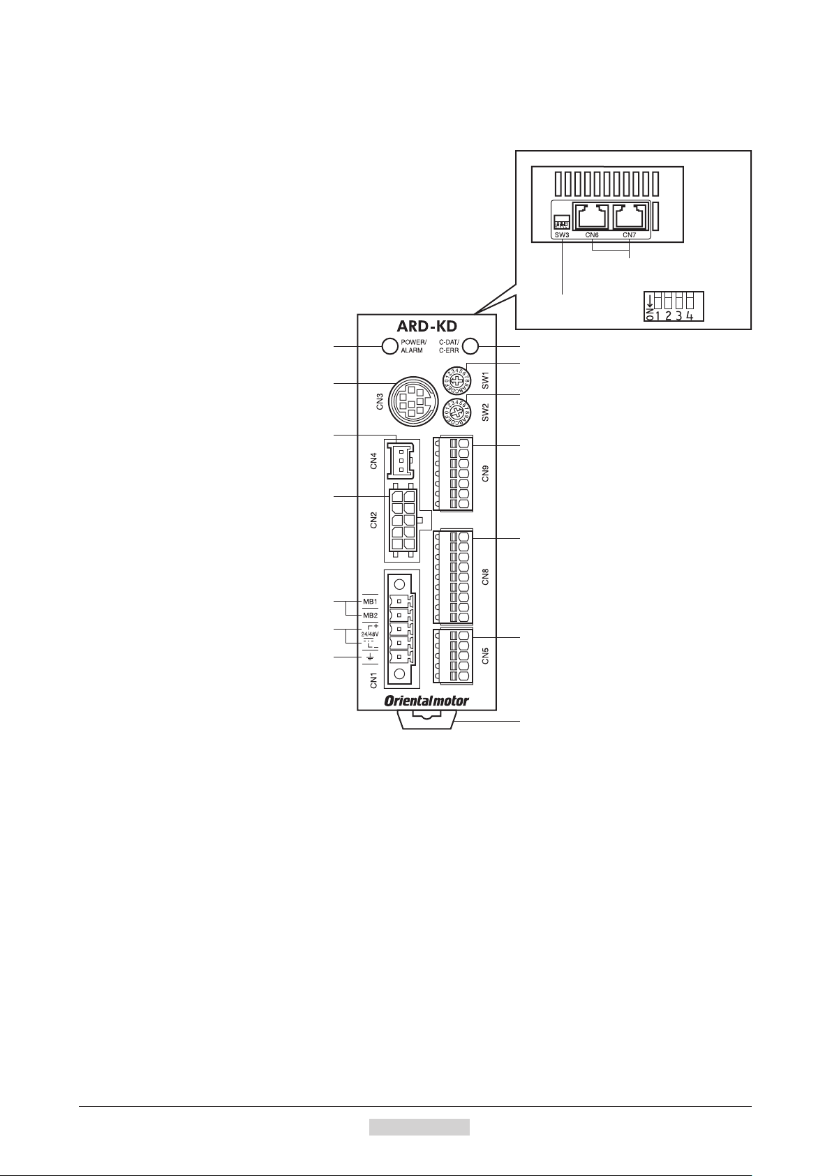
9.4 Names and functions of parts
Driver
POWER/ALARM LED C-DAT/C-ERR LED
Data edit connector (CN3)
RS-485 communication
connectors (CN6/CN7)
Function setting
switches (SW3)
Address number setting switch (SW1)
Transmission rate setting switch (SW2)
Battery connector (CN4)
Motor connector (CN2)
Electromagnetic brake terminals (CN1)
Power supply input terminals (CN1)
Frame Ground Terminal (CN1)
Output signal connector (CN9)
Input signal connector (CN8)
Sensor signal connector (CN5)
DIN lever
−22−
1Introduction
Page 23

Preparation
Name Description Page
POWER LED (Green) This LED is lit while the power is input.
ALARM LED (Red)
C-DAT LED (Green)
C-ERR LED (Red
)
Address number setting switch
(SW1)
Transmission rate setting switch
(SW2)
This LED will blink when an alarm generates. It is possible to check the generated
alarm by counting the number of times the LED blinks.
This LED will blink or illuminate steadily when the driver is communicating with
the master station properly via RS-485 communication.
T
his LED will illuminate when a RS-485 communication error occurs with the
master station.
Use this switch when controlling the system via RS-485 communication. Use this
switch and SW3-No.1 of the function setting switch, to set the address number
(slave address) of RS-485 communication. (Factory setting: 0)
Use this sw
itch when controlling the system via RS-485 communication. Set the
transmission rate of RS-485 communication. (Factory setting: 7)
Use this switch when controlling the system via RS-485 communication.
No.1: Using this switch and the address number setting switch (SW1), set the
address number (slave address) of RS-485 communication.
Function setting switches (SW3)
(Factory setting: OFF
N
o.2: Set the protocol of RS-485 communication. (Factory setting: OFF)
)
−
p.199
−
−
p.131
p.167
p.179
No.3: Not used.
No.4: Set the termination resistor (120 Ω) of RS-485 communication.
(Factory setting: OFF)
Electromagnetic brake terminals
(CN1-MB1/MB2)
Power supply input terminals
(CN1)
Frame Ground Terminal (CN1) Ground using a wire of AWG24 to 16 (0.2 to 1.25 mm
Connect the lead wires from the electromagnetic brake.
MB1: Electromagnetic brake − (black)
MB2: Electromagnetic brake + (white)
Connect th
r supply of the driver.
e powe
+: +24 VDC/48 VDC power supply input
−
: power supply GND
2
p.32
). p.36
Motor connector (CN2) Connect the motor cable or flexible motor cable to connect the motor. p.32
Data edit connector (CN3) Connect a PC in which the
MEXE02
Battery connector (CN4) Connect the accessory batter
has been installed, or the
y (sold separa
tely). p.38
OPX-2A
. p.36
Sensor signal connector (CN5) Connects the limit sensor. p.32
RS-485 communication
connectors (CN6/CN7)
Input signal connector (CN8) Connect the input signals cable.
Output signal connector (CN9) Connect the output signals cable.
Connect the RS-485 communication cable. p.37
p.32
1Introduction
−23−
Page 24
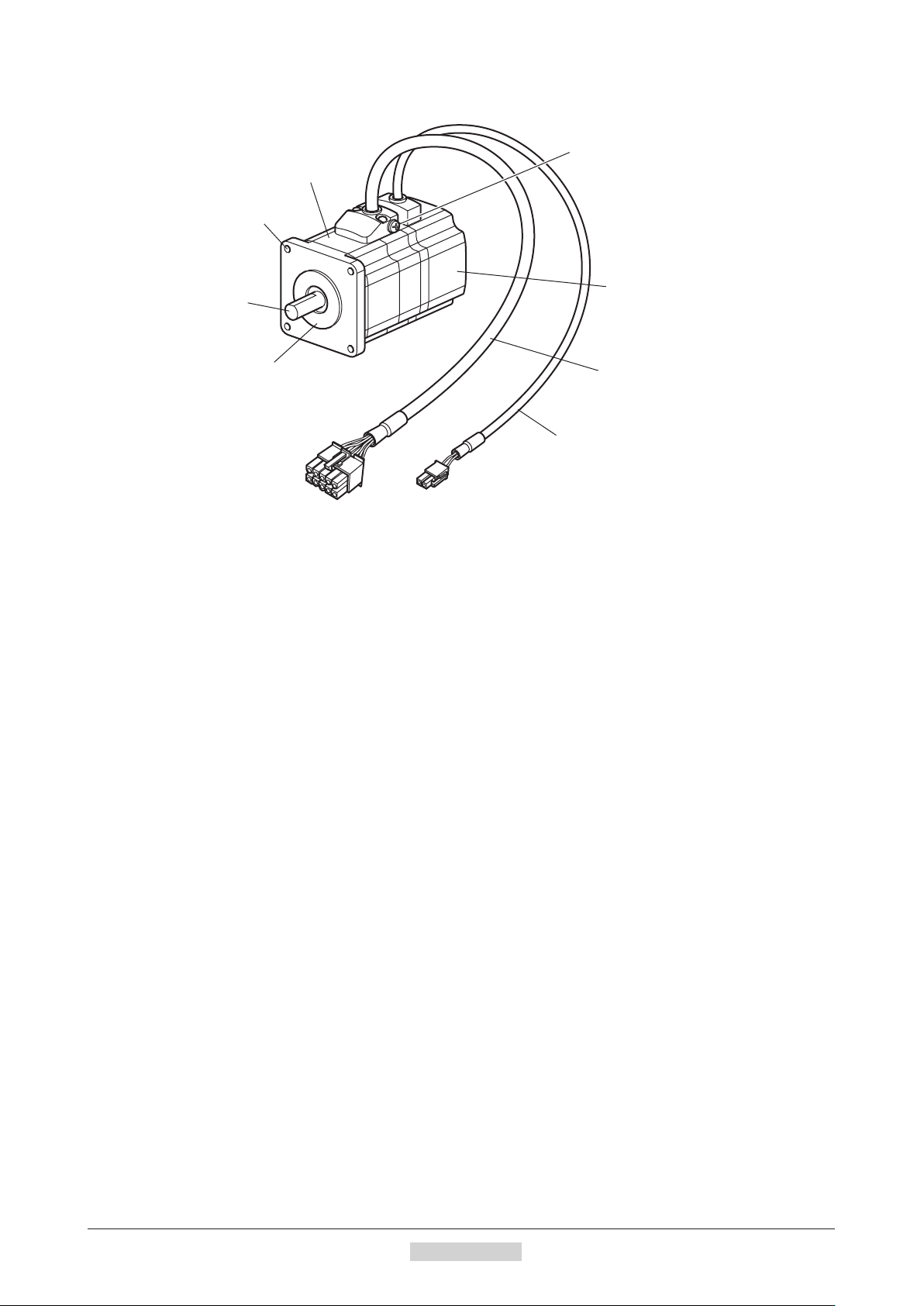
Preparation
Motor (Example: ARM66SMK)
Protective Earth Terminal (M4)
Motor
Mounting holes
(4 locations)
Output shaft
Pilot
Electromagnetic brake cable
Electromagnetic brake
Motor cable
−24−
1Introduction
Page 25

2 Installation and
connection
This part explains the installation method of the product, the mounting method of a load and the connection
method as well as I/O signals.
Table of contents
1 Installation ........................................ 26
1.1 Location for installation ..........................26
1.2 Installing the motor ................................26
1.3 Installing a load .....................................27
1.4 Permissible radial load and
permissible axial load .....................
1.5 Installing the driver ................................ 29
1.6 Installing the battery .............................. 30
1.7 Installing and wiring in compliance
with EMC Directive ................................ 30
.......2
2 Connection ........................................ 32
2.1 Connection example
(electromagnetic brake motor) ..............32
2.2 Grounding the motor and driver ............36
2.3 Connecting the data setter .................... 36
2.4
C
onnecting the RS-485 communication
cable ......................................................37
2.5 Connecting and charging the battery ....38
3 Explanation of I/O signals ............... 39
3.1 Assignment of direct I/O ........................39
Assignment to the input terminals ....................39
Changing the logic level setting of input
signals ...............................................................40
Assignment to the o
8
3.2 Assignment of network I/O .................... 43
Assignment of input signals ..............................43
Assignment to the output terminals ..................45
3.3 Input signals .......................................... 47
3.4 Output signals .......................................52
3.5 Sensor input .......................................... 56
3.6 Genera
l signals (R0 to R15) .
utput terminals .
.................57
.................41
Page 26
Installation
Metal plate
1 Installation
This chapter explains the installation location and installation methods of the motor and driver, along with load
installation. The installation and wiring methods in compliance with the EMC Directive are also explained.
1.1 Location for installation
The motor and driver has been designed and manufactured to be installed within another device. Install them in a
well-ventilated location that provides easy access for inspection.
T
he location must also satisfy the following conditions:
•Inside an enclosure that is installed indoors (provide vent holes)
•Operating ambient temperature
Motor: −10 to +50 °C (+14 to +122 °F) (non-freezing)
Harmonic geared type: 0 to +40 °C (+32 to +104 °F) (non-freezing)
Driver: 0 to +50 °C (+32 to +122 °F) (non-freezing)
•Operating ambient humidity 85% or less (non-condensing)
•Area that is f
•Area not exposed to direct sun
•Area free of excessive amount of dust, iron particles or the like
•Area not subject to splashing water (rain, water droplets), oil (oil droplets) or other liquids
•Area free of excessive salt
•Area not subject to continuous vibration or excessive shocks
•Area free of excessive electromagnetic
•Area free of radioactive materials, magnetic fields or vacuum
•1000 m (3300 ft.) or lower above sea level
ree of ex
plosive atmosphere or toxic gas (such as sulfuric gas) or liquid
noise (from welders, pow
er machinery, etc.)
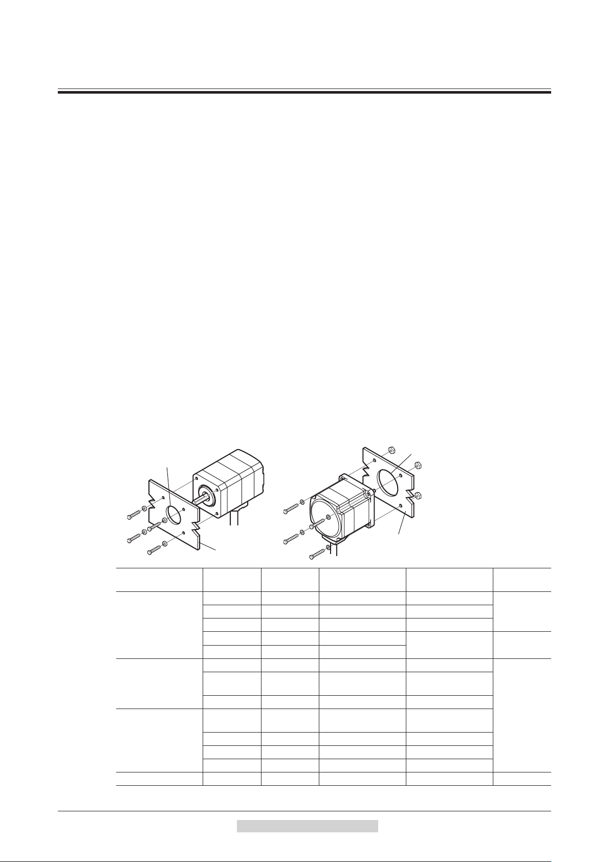
1.2 Installing the motor
The motor can be installed in any direction.
To allow for heat dissipation and prevent vibration, install the motor on a metal surface of sufficient strength.
•Installation method A
Pilot
Type
Standard
TH
geared
PS
geared
PN
geared
Harmonic geared ∗1
Harmonic geared ∗2 90 (3.54) M8 4 (560)
AR24, AR46
*3
*4
AR98
and
type only.
Frame size
[mm (in.)]
20 (0.79) M2 0.25 (35) 2.5 (0.098)
42 (1.65) M3 1 (142) 4.5 (0.177)
60 (2.36) M4 2 (280)
85 (3.35) M6 3 (420)
28 (1.10) M2.5 0.5 (71) 4 (0.157)
42 (1.65)
60 (2.36)
90 (3.54) M8 4 (560) 15 (0.591)
28
3
42 (1.65) M4 2 (280) 8 (0.315)
60 (2.36) M5 2.5 (350) 10 (0.394)
90 (3.54) M8 4 (560) 15 (0.591)
AR66
(1.10)
0 (1.18)
type only.
•Installation method B
Pilot
Metal plate
Nominal size
M4 2 (280) 8 (0.315)
M3 1 (142) 6 (0.236)
Tightening torque
[N·m (oz-in)]
Effective depth of
bolt [mm (in.)]
−
−
Installation
method
A28 (1.10) M2.5 0.5 (71) 2.5 (0.098)
B
A
B
−26−
2Installationandconnection
Page 27
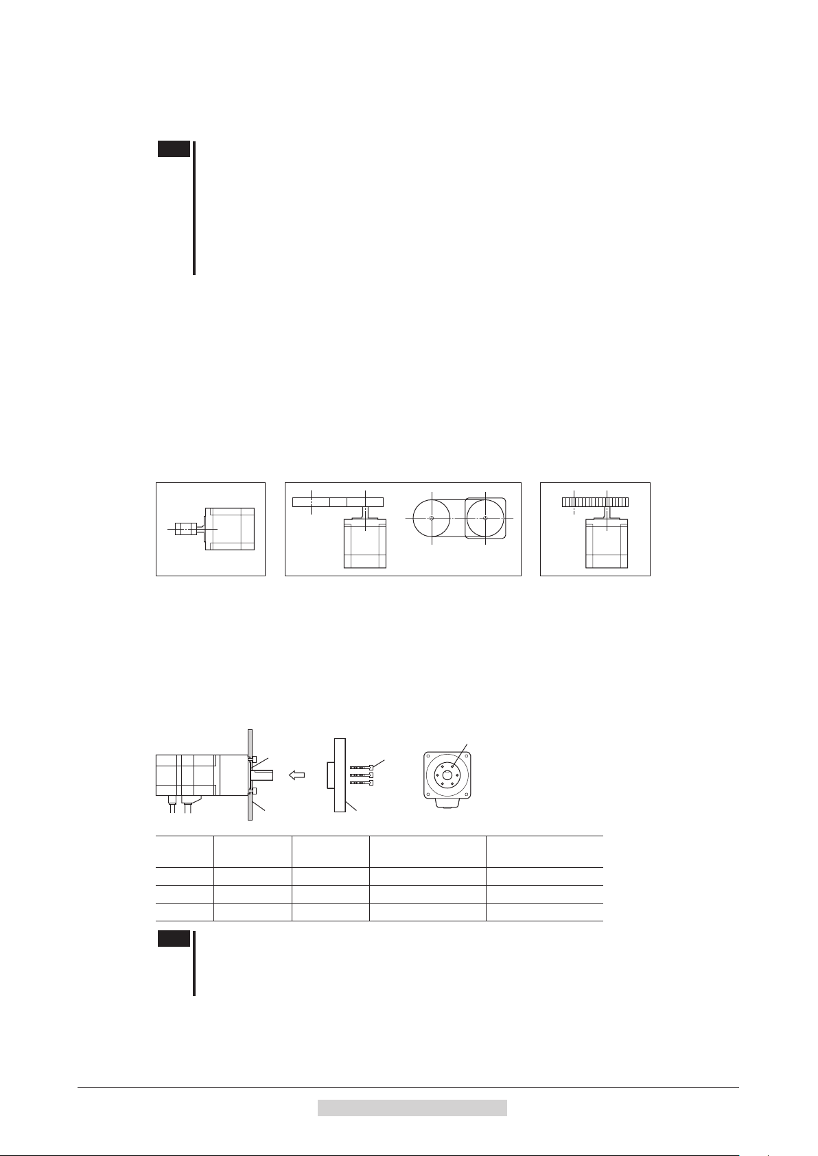
1.3 Installing a load
When connecting a load to the motor, align the centers of the motor output shaft and load shaft.
Flexible couplings are available as accessories.
Note
Using a coupling
Align the centers of the motor output shaft and load shaft in a straight line.
Using a belt drive
Align the motor output shaft and load shaft in parallel with each other, and position both pulleys so that the line
connecting their centers is at a right angle to the shafts.
Using a gear drive
Align the motor output shaft and gear shaft in parallel with each other, and let the gears mesh at the center of the tooth
widths.
•When coupling the load to the motor, pay attention to the centering of the shafts, belt tension,
parallelism of the pulleys, and so on. Securely tighten the coupling and pulley set screws.
•Be careful not to damage the output shaft or bearings when installing a coupling or pulley to the
motor output shaft.
•Do not modify or machine the motor output shaft. Doing so may damage the bearings and
de
stroy
the motor.
•Do not apply strong force using hammer or other tools when removing the parallel key. Doing so
may damage the motor output shaft and bearings (ball bearings).
Installation
• Using a coupling • Using a belt drive • Using a gear drive
Using a parallel key (geared motor)
When connecting the load and gear output shaft with a key slot, secure the load using the key supplied with the gear
output shaft after machining the key slot on the load.
Installing on the ange surface (Harmonic geared type)
With a Harmonic geared type (excluding
holes provided on the flange surface.
Flange
Metal plate
Model Nominal size
AR24
AR46
AR66
M3 4 1.4 (198) 4 (0.157)
M3 6 1.4 (198) 5 (0.2)
M4 6 2.5 (350) 6 (0.24)
Number of
bolts
AR98
), a load can be installed directly to the gear using the load mounting
Load mounting holes
Bolts
Load
Tightening torque
[N·m (oz-in)]
Effective depth of
bolt [mm (in.)]
Note
•When installing a load on the flange surface, the load cannot be mounted using the key slot in
the output shaft.
•Design an appropriate installation layout so that the load will not contact the metal plate or bolts
used for installing the motor.
2Installationandconnection
−27−
Page 28

Installation
1.4 Permissible radial load and permissible axial load
Note
•If the radial load or axial load exceeds the specified allowable value, repeated load applications
may cause the bearing (ball bearings) or output shaft of the motor to undergo a fatigue failure.
•With a double shaft type, do not apply load torque, radial load or axial load to the output shaft on
the opposite side of the motor output shaft.
Type Model Gear ratio
AR14
AR15
AR24
AR26
Standard
TH
geared
PS
geared
PN
geared
AR46
AR66
AR69
AR98
AR24
AR46
AR66
AR98
AR24
AR46
AR66
AR98
AR24
AR46
AR66
AR98
Permissible radial load [N (lb.)]
Distance from the tip of motor output shaft [mm (in.)]
0 (0) 5 (0.2) 10 (0.39) 15 (0.59) 20 (0.79)
12 (2.7) 15 (3.3)
25 (5.6) 34 (7.6) 52 (11.7)
−
−
−
5
7.2
10
5
2
36
50
5 200 (45) 220 (49) 250 (56) 280 (63) 320 (72)
7.2
10
25
36
50
5
7.2
10
25 850 (191) 940 (210) 1050 (230) 1190 (260) 1380 (310)
36 930 (200) 1030 (230) 1150 (250) 1310 (290) 1520 (340)
50 1050 (230) 1160 (260) 1300 (290) 1480 (330)
−
5 200 (45) 220 (49) 250 (56) 280 (63) 320 (72)
7.2
10
25
36
50
5 480 (108) 520 (117) 550 (123) 580 (130) 620 (139)
7.2
10
25 850 (191) 940 (210) 1050 (230) 1110 (240) 1190 (260)
36
50 1050 (230) 1160 (260) 1300 (290) 1380 (310) 1490 (330)
35 (7.8) 44 (9.9) 58 (13) 85 (19.1)
90 (20) 100 (22) 130 (29) 180 (40) 270
260 (58) 290 (65) 340 (76) 390 (87) 480 (108)
15 (3.3) 17 (3.8) 20 (4.5) 23 (5.1)
10 (2.2) 14 (3.1) 20 (4.5) 30 (6.7)
70 (15.7) 80 (18) 100 (22) 120 (27) 150 (33) 40 (9)
220 (49) 250 (56) 300 (67) 350 (78) 400 (90) 100 (22)
45 (10.1) 60 (13.5) 80 (18) 100 (22)
73 (16.4) 84 (18.9) 100 (22) 123 (27)
109 (24) 127 (28) 150 (33) 184 (41)
250 (56) 270 (60) 300 (67) 340 (76) 390 (87)
330 (74) 360 (81) 400 (90) 450 (101) 520 (117)
480 (108) 540 (121) 600 (135) 680 (153) 790 (177)
45 (10.1) 60 (13.5) 80 (18) 100 (22)
100 (22) 120 (27) 150 (33) 190 (42)
250 (56) 270 (60) 300 (67) 340 (76) 390 (87)
330 (74) 360 (81) 400 (90) 450 (101) 520 (117)
480 (108) 540 (121) 600 (135) 680 (153) 790 (177)
930 (200) 1
030 (230) 1150 (250) 1220 (270) 1300 (290)
* The brackets < > indicate the value for the electromagnetic brake type.
− − −
− −
−
(60)
−
−
−
−
−
1710 (380)
−
−
Permissible axial
load [N (lb.)]
0.7 (0.157)
0.9 (0.2)
1.5 (0.33)
<2.1 (0.47)>
2.2 (0.49)
<2.7 (0.6)>
4.6 (1.03)
<6.1 (1.37)>
.8 (1.98)
8
<11.8 (2.6)>
13.7 (3)
<16.7 (3.7)>
18 (4)
<24 (5.4)>
10 (2.2)
15 (3.3)
20 (4.5)
0 (11.2)
5
100 (22)
300 (67)
20 (4.5)
100 (22)
300 (67)
∗
∗
∗
∗
∗
∗
−28−
2Installationandconnection
Page 29

Installation
35 mm
50 mm or more
100 mm
Type Model Gear ratio
AR24
Harmonic
geared
AR46
AR66
AR98
−
1090 (240) 1150 (250) 1230 (270) 1310 (290) 1410 (310) 1300 (290)
Permissible moment load of the Harmonic geared type
When installing an arm or table on the flange surface, calculate the moment load using the formula below if the flange
surface receives any eccentric load. The moment load should not exceed the permissible value specified in the table.
Moment load: M [N·m (oz-in)] = F × L
Model
AR24
AR46
AR66
Permissible moment load
[N·m (oz-in)]
2.9 (410)
5.6 (790)
11.6 (1640)
1.5 Installing the driver
Installation method
Mount the driver to a 35 mm (1.38 in.) width DIN rail.
When installing two or more drivers in parallel, it is possible to install them closely
in the horizontal direction.
Provide a minimum clearance of 50 mm (1.97 in.) in the vertical direction.
When installing three or more drivers closely, the heat generation of the inside drivers
become high. Install the less frequently used drivers toward the in
U
se the "overheat warning" parameter to check the inside temperature of the driver.
Note
•Install the driver in an enclosure whose pollution degree is 2
or better environment, or whose degree of protection is IP54
minimum.
•Do not install any equipment that generates a large amount of heat
or noise near the driver.
•Do not install the driver underneath the controller or other
equipment vulnerable to heat.
•If the ambient temperature of the driver exceeds 50 °C (122 °F),
improve the
ve
by using fans or creating spaces between the drivers.
•Be sure to install the driver vertically (vertical position).
Permissible radial load [N (lb.)]
Distance from the tip of motor output shaft [mm (in.)]
0 (0) 5 (0.2) 10 (0.39) 15 (0.59) 20 (0.79)
100 (22) 135 (30) 175 (39) 250 (56)
180 (40) 220 (49) 270 (60) 360 (81) 510 (114) 220 (49)
320 (72) 370 (83) 440 (99) 550 (123) 720 (162) 450 (101)
L
F
−
Permissible axial
load [N (lb.)]
140 (31)
side.
ntilation condition such as providing forced cooling
Pull down the driver's DIN lever and lock it. Hang the hook at the rear to the DIN rail, and push in the driver.
After installation, secure the both sides of the driver with the end plate.
Hook
DIN rail
DIN lever
2Installationandconnection
End plate
−29−
Page 30
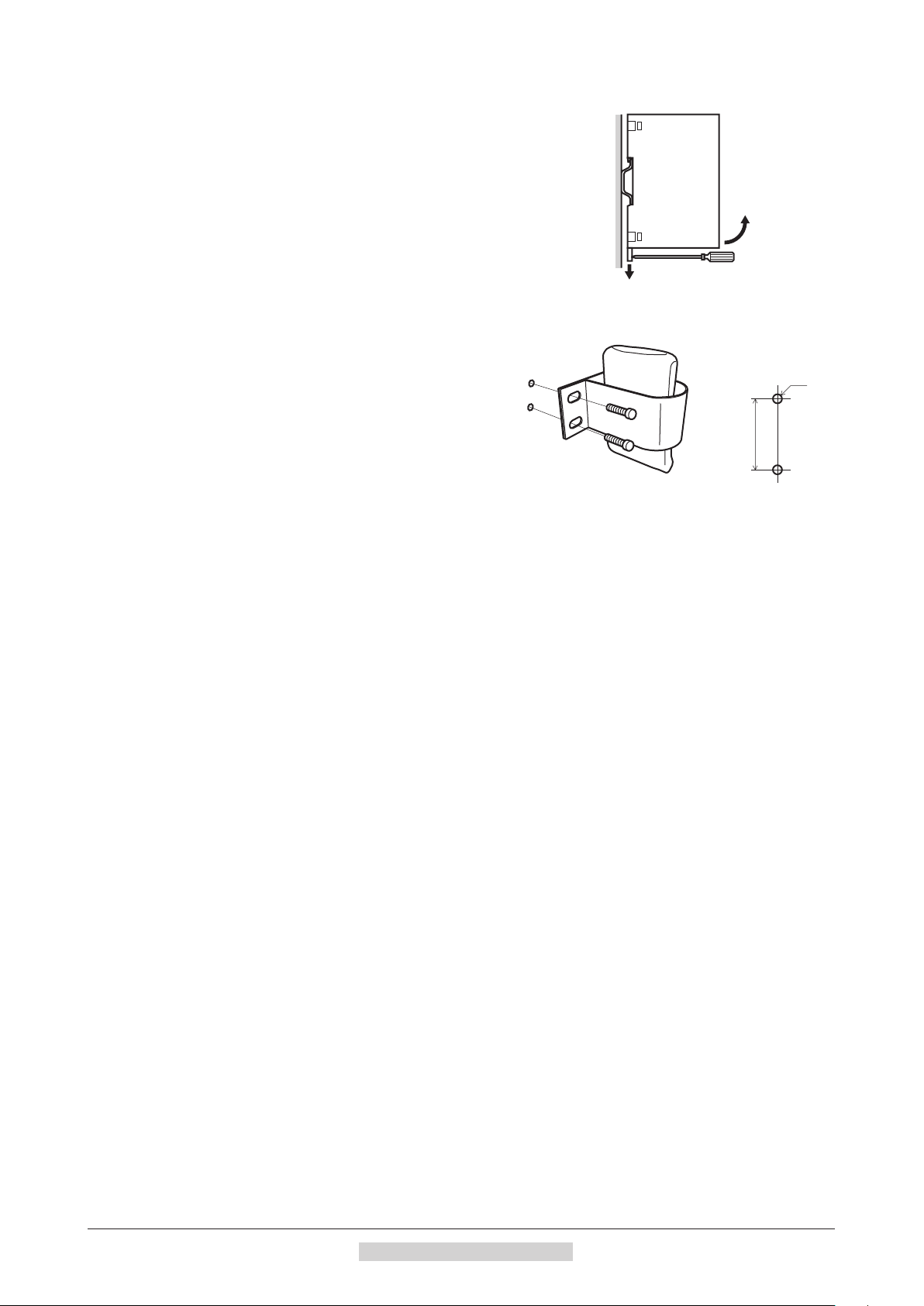
Installation
•
Removing from DIN rail
Pull the DIN lever down until it locks using a flat tip screwdriver, and lift the
bottom of the driver to remove it from the rail.
Use force of about 10 to 20 N (2.2 to 4.5 lb.) to pull the DIN lever to lock it.
Excessive force may damage the DIN lever.
1.6 Installing the battery
A battery and battery holder are included in an accessory
battery set
Use the battery holder to secure the battery.
See p.210 for accessory.
BAT01B
(sold separately).
Battery installation
dimensions
M4
13±0.3 mm
(0.51±0.012 in.)
1.7 Installing and wiring in compliance with EMC Directive
Effective measures must be taken against the EMI that the motor and driver may give to adjacent control-system
equipment, as well as the EMS of the motor and driver itself, in order to prevent a serious functional impediment
in the machinery. The use of the following installation and wiring methods will enable the motor and driver to be
compliant with the EMC directive. Refer to "8 CE Marking" o
riental Motor conducts EMC measurements on its motors and drivers in accordance with "Example of motor and
O
driver installation and wiring" on p.31. The user is responsible for ensuring the machine's compliance with the EMC
Directive, based on the installation and wiring explained below.
Connecting the power supply
Use a DC power supply compliant with the EMC Directive.
Use a shielded cable for wiring and wire/ground the pow
Refer to "Wiring the power supply cable and I/O signal cable" for how to ground the shielded cable.
Connecting noise lter for power supply line
•Connect a noise filter in the DC power supply input to prevent the noise generated in the driver from propagating
externally through the power supply line.
•When using a power supply transformer, be sure to connect a noise filter to the AC
transformer.
•For a noise filter, use HF2010A (SOSHIN ELECTRIC CO.,LTD), FN2070-10-06 (Schaffner EMC) or equivalent
product.
•Install the noise filter as close to the AC input terminal of DC power supply as possible. Use cable clamps and other
means to secure the AC input cables (AWG18: 0.75 mm
firmly to the surface of the enclosure.
•Connect the ground terminal of the noise filter to the grounding point, using as thick and short a wire as possible.
•Do not place the AC input cable parallel with the noise filter output cable. Parallel placement will reduce noise
filter effectiveness if the enclosure's internal noise is directly coupled to the power supply cable by means of stray
capacita
nce.
n p.19 for the applicable standards.
er supply over the shortest possible distance.
input side of the power supply
2
or more) and output cables (AWG18: 0.75 mm2 or more)
−30−
How to ground
The cable used to ground the driver and noise filter must be as thick and short as possible so that no potential
difference is generated. Choose a large, thick and uniformly conductive surface for the grounding point.
•Grounding the motor
Be sure to ground the Protective Earth Terminal of the motor. Refer to p.36 for grounding method.
•Grounding the driver
Refer to p.36 for grounding method.
2Installationandconnection
Page 31

Installation
A: Cable cramp
PE
Wiring the power supply cable and I/O signal cable
Use a shielded cable for the power supply cable and I/O signal cable, and keep it as short as possible.
To ground a shielded cable, use a metal cable clamp or similar
device that will maintain contact with the entire circumference
of the cable. Attach a cable clamp as close to the end of the
Shielded cable
Cable clamp
cable as possible, and connect it as shown in the figure.
Notes about installation and wiring
•Connect the motor, driver and other peripheral control equipment directly to the grounding point so as to prevent a
potential difference from developing between grounds.
•When relays or electromagnetic switches are used together with the system, use noise filters and CR circuits to
suppress surges generated by them.
•Keep cables as short as possible without coiling and bundling extra lengths.
lace the power cables such as the motor and power supply cables as far apart [200 mm (7.87 in.)] as possible from
P
•
the signal cables. If the power cables and signal cables have to cross, cross them at a right angle. Place the AC input
cable and output cable of a noise filter separately from each other.
•When extending the distance between the motor and driver, it is recommended that an accessory m
s
eparately) should be used. The EMC measures are conducted using the Oriental Motor extension cable.
otor cable (sold
Example of motor and driver installation and wiring
RS-485 communication cable
OPX-2A
Motor
Controller
PE
Motor cable
(Shielded cable)
AC
Noise
Filter
DC power
supply
PEPE
Shielded
cable
BAT01B
A
FG
Driver
FG
Shielded
cable
A
FG
Grounded panel
Sensor
Shielded cable
Precautions about static electricity
Static electricity may cause the driver to malfunction or suffer damage. While the driver is receiving power, handle
the driver with care and do not come near or touch the driver.
Always use an insulated screwdriver to adjust the driver's switches.
Note
The driver uses parts that are sensitive to electrostatic charge. Before touching the driver, turn off
the power to prevent electrostatic charge from generating. If an electrostatic charge is impressed
on the driver, the driver may be damaged.
2Installationandconnection
−31−
Page 32

Connection
2 Connection
This chapter explains how to connect the motor, I/O signals and power supply to the driver, as well as grounding
method.
2.1 Connection example (electromagnetic brake motor)
Wiring the CN5/CN8/CN9 connector
Button of the orange color
Lead wire
Cable for motorMotor cable
Connect to CN2
∗
Insert the lead wire
while pushing the
button of the orange
color with a screwdriver.
Output signals
Connect to CN9
Electromagnetic
brake cable
DC power supply
24 VDC±5%
or 48 VDC±5%
Wiring the CN1 connector
Screwdriver
(connector screw size: M2)
Tightening torque:
0.22 to 0.25 N·m
(31 to 35 oz-in)
Lead wire
Note
•Have the connector plugged in securely. Insecure connections may cause malfunction or damage to the motor
or driver.
•When unplugging the connector, do so while pressing the latches on the connector.
•When plugging/unplugging the connector, turn off the power and wait for the POWER LED to turn off before
doing so.
•When connecting, check the silk screen of the driver and pay attention to the po
Reverse-polarity connection may cause damage to the driver. The power-supply circuit and the RS485 communication circuit are not insulated. Therefore, when controlling multiple drivers via RS-485
communication, the reverse polarity of the power supply will cause a short circuit and may result in damage to
the drivers.
•The lead wires of the "cable for electromagnetic b
polarities. If the lead wires are connected with their polarities reversed, the electromagnetic brake will not
operate properly.
•If the distance between the motor and driver is extended to 20 m (65.6 ft.) or longer, use a power supply of
24 VDC±4%.
•When installing the motor to a moving part, use an accessory flexible cable offering excellent
flexible motor cable, refer to p.208.
•Do not wire the power supply cable of the driver in the same cable duct with other power lines or motor cables.
Doing so may cause malfunction due to noise.
Cable for electromagnetic brake
Connect to CN1
+24 V (+48 V)
GND
Pay attention to the
polarity of the power
supply.
+24 VDC
GND
Input signals
Black
∗
White
FG
Screwdriver
(connector screw size: M2.5)
Tightening torque: 0.4 N·m (56 oz-in)
* Keep 30 m (98.4 ft.) or less for the wiring distance between the motor and driver.
Connect to CN8
Sensor signals
Connect to CN5
larity of the power supply.
ra
ke" have polarities, so connect them in the correct
flex
ibility. For the
−32−
2Installationandconnection
Page 33

Power supply current capacity
5
Model
AR14
AR15
AR24
AR26
AR46
AR66
AR69
AR98
Input power
supply voltage
24 VDC±5%
24 VDC±5%
48 VDC±5%
Standard type Electromagnetic brake type
0.4 A or more
0.5 A or more
1.3 A or more 1.37 A or more
1.72 A or more 1.8 A or more
3.55 A or more 3.8 A or more
3.45 A or more 3.7 A or more
2.85 A or more 3.1 A or more
Pin assignment list
•CN1
Pin No. Signal name Description
1 MB1 Electromagnetic brake − (Black)
2 MB2 Electromagnetic brake + (White)
3 + 24 VDC/48 VDC power supply
4
5 FG Frame Ground
−
Power supply ground
Power supply current capacity
−
−
1
•
•
•
5
Connection
•Applicable lead wire:
AWG24 to 16 (0.2 to 1.25 mm
•Length of the insulation cover
which can be peeled:
7 mm (0.28 in.)
2
)
•CN5
Pin No. Signal name Description
1 +LS Limit sensor input +
2
−
LS Limit sensor input
3 HOMES Mechanical home sensor input
4 SLIT Slit sensor input
5 IN-COM2 Sensor common input
•CN8
Pin No. Signal name Description
1 IN0 Control input 0 [HOME]
2 IN1 Control input 1 [START]
3 IN2 Control input 2 [M0]
4 IN3 Control input 3 [M1]
5 IN4 Control input 4 [M2]
6 IN5 Control input 5 [FREE]
7 IN6 Control input 6 [STOP]
8 IN7 Control input 7 [ALM-RST]
9 IN-COM1 Input signal common
* [ ]: Initial value
•CN9
Pin No. Signal name Description
1 OUT0 Control output 0 [HOME-P]
2 OUT1 Control output 1 [END]
3 OUT2 Control output 2 [AREA1]
4 OUT3 Control output 3 [READY]
5 OUT4 Control output 4 [WNG]
6 OUT5 Control output 5 [ALM]
7 OUT-COM Output signal common
* [ ]: Initial value
•Applicable lead wire:
1
AWG26 to 20 (0.14 to 0.5 mm
−
•
•
•Length of the insulation cover
•
which can be peeled:
2
)
8 mm (0.31 in.)
1
•Applicable lead wire:
•
AWG26 to 20 (0.14 to 0.5 mm
•
•
•Length of the insulation cover
•
•
which can be peeled:
8 mm (0.31 in.)
9
1
•Applicable lead wire:
•
AWG26 to 20 (0.14 to 0.5 mm
•
•
•Length of the insulation cover
•
•
which can be peeled:
8 mm (0.31 in.)
7
2
)
2
)
2Installationandconnection
−33−
Page 34

Connection
Connecting to a current sink output circuit (NPN specications)
DriverController
12 to 24 VDC
0
R
10 mA or less
OUT0
CN9
R0
R0
R0
OUT1
OUT2
OUT3
Output saturated
voltage
3 V max.
R0
0
R
0 V
24 VDC
0 V
OUT4
OUT5
OUT-COM
IN0
IN1
IN2
IN3
IN4
IN5
IN6
IN7
IN-COM1
CN8
4.4 kΩ
4.4 kΩ
4.4 kΩ
4.4 kΩ
4.4 kΩ
4.4 kΩ
4.4 kΩ
4.4 kΩ
1 kΩ
1 kΩ
1 kΩ
1 kΩ
1 kΩ
1 kΩ
1 kΩ
1 kΩ
−34−
Note
NPN sensor
0 V
24 VDC
+LS
-
LS
HOMES
SLIT
IN-COM2
CN5
4.4 kΩ
1 kΩ
4.4 kΩ
1 kΩ
4.4 kΩ
1 kΩ
4.4 kΩ
1 kΩ
•Use input signals at 24 VDC.
•Use output signals at 24 VDC 10 mA or less. If the current exceeds 10 mA, connect an external
resistor R0.
•The saturated voltage of the output signal is 3 VDC maximum.
2Installationandconnection
Page 35

Connecting to a current source output circuit (PNP specications)
DriverController
Connection
12 to 24 VDC
R
R0
R0
R
0
0
10 mA or less
OUT0
OUT1
OUT2
OUT3
CN9
Output saturated
voltage
3 V max.
R0
R0
0 V
24 VDC
0 V
OUT4
OUT5
OUT-COM
IN0
IN1
IN2
IN3
IN4
IN5
IN6
IN7
IN-COM1
CN8
4.4 kΩ
4.4 kΩ
4.4 kΩ
4.4 kΩ
4.4 kΩ
4.4 kΩ
4.4 kΩ
4.4 kΩ
1 kΩ
1 kΩ
1 kΩ
1 kΩ
1 kΩ
1 kΩ
1 kΩ
1 kΩ
Note
PNP sensor
0 V
24 VDC
+LS
-
LS
HOMES
SLIT
IN-COM2
CN5
4.4 kΩ
1 kΩ
4.4 kΩ
1 kΩ
4.4 kΩ
1 kΩ
4.4 kΩ
1 kΩ
•Use input signals at 24 VDC.
•Use output signals at 24 VDC 10 mA or less. If the current exceeds 10 mA, connect an external
resistor R0.
•The saturated voltage of the output signal is 3 VDC maximum.
2Installationandconnection
−35−
Page 36

Connection
PE
2.2 Grounding the motor and driver
Grounding the motor
Be sure to ground the Protective Earth Terminal of the motor. (It is no need to ground
when the driver power supply voltage is 24 VDC.)
Grounding wire: AWG18 (0.75 mm
Tightening torque: 1.2 N·m (170 oz-in)
When grounding, use a round terminal and secure it with a mounting screw with a
washer. Ground wires and crimp terminals are not supplied.
Grounding the driver
Ground the FG terminal of power supply connector
(CN1) as necessary. Ground using a wire of AWG24
to 16 (0.2 to 1.25 mm
protective earth terminal with a welder or any other
power equipment.
2
), and do not share the
2
) or more
+24 VDC
GND
Connect to
CN1
FG
2.3 Connecting the data setter
Connect the
setting software to the data edit connector (CN3) on the driver.
OPX-2A
cable or communication cable for the data
The power supply connector (CN1), data edit connector (CN3) and RS-485
communication connectors (CN6/CN7) of the driver are not electrically insulated. When
grounding the positive terminal of the power supply, do not connect any equipment (PC,
etc.) whose negative terminal is grounded. Doing so may cause the driver and these
equipment to short, damaging both.
OPX-2A cable or communication
cable for the data setting software
−36−
2Installationandconnection
Page 37

2.4 Connecting the RS-485 communication cable
0 V
Connect this cable if you want to control your product via RS-485 communication. Connect the RS-485
communication cable to CN6 or CN7 on the driver.
You can use the vacant connectors to connect a different driver. A driver link cable is available as an accessory (sold
separately). See p.210. You can also use a commercial LAN cable to link drivers.
Drivers can be linked.
Connection
RS-485 communication
connectors (CN6/CN7)
Function setting switches (SW3)
CN6/CN7 pin assignments
Pin No. Signal name Description
1 N.C. Not used
2 GND GND
3 TR+ RS-485 communication signal (+)
4 N.C. Not used
5 N.C. Not used
1 N.C.
2 GND
3 TR+
4 N.C.
5 N.C.
6 TR
7 N.C.
8 N.C.
−
RS-485 communication signal (−)
-
6 TR
7 N.C. Not used
8 N.C. Not used
1 N.C.
2 GND
3 TR+
4 N.C.
5 N.C.
6 TR
7 N.C.
8 N.C.
SW3-No.4
120 Ω
-
∗
* The GND line is used in common with CN1 (not insulated).
2Installationandconnection
−37−
Page 38

Connection
2.5 Connecting and charging the battery
Connect an accessory battery set
When the battery is connected to the battery connector (CN4) of the driver
and the power is turned on, the battery will start charging.
It takes approximately 32 hours to fully charge the battery [at an ambient
temperature of 20 °C (68 °F)]. See p.210 for accessories.
Battery specifications
Battery type Sealed nickel-metal hydride battery
Nominal voltage 2.4 V
Rated capacity 1900 mAh
Mass 0.10 kg
Expected life Approximately 4 years ∗1
Charging time 32 hours ∗1
Data retention period Approximately 360 hours (Approximately 15 days) ∗1∗2
Ambient temperature 0 to +40 °C (+32 to +104 °F) (non-freezing)
Humidity 45 to 85% (non-condensing)
*1 At an ambient temperature of 20 °C (68 °F)
*2 After the power is cut
off
BAT01B
with the battery fully charged
(sold separately) for the absolute-position backup system.
Battery power supply GND
Battery power supply input
Not used
−38−
2Installationandconnection
Page 39

3 Explanation of I/O signals
In this manual, I/O signals are described as follows.
•Direct I/O: I/O signals accessed via input signal connector (CN8) and output signal connector (CN9)
•Network I/O: I/O signals accessed via RS-485 communication
Set the following parameters using the
3.1 Assignment of direct I/O
Assignment to the input terminals
The input signals shown below can be assigned to the input terminals IN0 to IN7 of CN8 by setting parameters.
For details on input signals, refer to p.47.
Direct I/O signal name Initial value Direct I/O signal name Initial value
IN0 3: HOME IN4 50: M2
IN1 4: START IN5 16: FREE
IN2 48: M0 IN6 18: STOP
IN3 49: M1 IN7 24: ALM-RST
Assignment No. Signal name Function
0 Not used Set when the input terminal is not used.
1 FWD Continuous operation in the positive direction.
2 RVS Continuous operation in the negative direction.
3 HOME Return-to-home operation.
4 START Positioning operation.
5 SSTART Sequential positioning operation.
6 +JOG JOG operation in the positive direction.
7
8 MS0
9 M
10 MS2
11 MS3
12 MS4
13 MS5
16 FREE Stop the motor excitation and release the electromagnetic brake.
17 C-ON Motor excitation switching between excitation and non-excitation.
18 STOP Stop of the motor operation.
24 ALM-RST Reset of the current alarm.
25 P-PRESET Position preset.
26 P-CLR Reset of the absolute position error alarm.
27 HMI Release of the function limitation of the
32 R0
33 R1
34 R2
35 R3
36 R4
37 R5
38 R6
39 R7
40 R8
41 R9
42 R10
43 R11
44 R12
45 R13
−
JOG JOG operation in the negative direction.
S1
OPX-2A, MEXE02
Direct positioning opera
General signals. Use these
ia RS-485 communication.
v
or RS-485 communication.
tion.
signals when controlling the system
OPX-2A
Explanation of I/O signals
MEXE02
or
.
2Installationandconnection
−39−
Page 40

Explanation of I/O signals
Assignment No. Signal name Function
Related parameters
IN0 input function selection
IN1 input function selection 4: START
IN2 input function selection 48: M0
IN3 input function selection 49: M1
IN4 input function selection 50: M2
IN5 input function selection 16: FREE
IN6 input function selection 18: STOP
IN7 input function selection 24: ALM-RST
46 R14
47 R15
48 M0
49 M1
50 M2
51 M3
52 M4
53 M5
Parameter name Description Initial value
General signals. Use these signals when controlling the system
via RS-485 communication.
Select the operation data No. using these six bits.
3: HOME
Assigns the following input signals to
IN0 to IN7 of the input terminals.
0: Not used
1: FWD
2: RVS
3: HOME
4: START
5: SSTART
6: +JOG
7: −JOG
Note
•Do not assign the same input signal to multiple input terminals. When the same input signal
8: MS0
9: MS1
10: MS2
11: MS3
12: MS4
13: MS5
16: FREE
17: C-ON
18: STOP
24: ALM-RST
25: P-PRESET
26: P-CLR
27: HMI
32: R0
33: R1
34: R2
35: R3
36: R4
37: R5
38: R6
39: R7
40: R8
41: R9
42: R10
43: R11
44: R12
45: R13
46: R14
47: R15
48: M0
49: M1
50: M2
is assigned to multiple input terminals, the function will be executed if any of the terminals
becomes active.
•The ALM-RST input and P-CLR input will be executed when turning from ON to OFF.
The P-PRESET input will be executed when turning from OFF to ON.
•When the C-ON input and HMI input are not assig
ned to the input term
always be set to ON. When assigning to both direct I/O and network I/O, the function will be
executed when both of them are set to ON.
Changing the logic level setting of input signals
You can change the logic level setting for input terminals IN0 to IN7 using the parameter.
Related parameters
Parameter name Description Setting range Initial value
IN0 input logic level setting
IN1 input logic level setting
IN2 input logic level setting
IN3 input logic level setting
IN4 input logic level setting
IN5 input logic level setting
IN6 input logic level setting
IN7 input logic level setting
Changes the logic level setting for
input terminals IN0 to IN7.
0: Normally open
1: Normally closed
51: M3
52: M4
53: M5
inals, these inputs will
0
−40−
2Installationandconnection
Page 41

Explanation of I/O signals
Assignment to the output terminals
The output signals shown below can be assigned to the output terminals OUT0 to OUT5 of CN9 by setting
parameters. For details on output signals, refer to p.52.
Direct I/O signal name Initial value Direct I/O signal name Initial value
OUT0 70: HOME-P OUT3 67: READY
OUT1 69: END OUT4 66: WNG
OUT2 73: AREA1 OUT5 65: ALM
Assignment No. Signal name Function
0 Not used Set when the output terminal is not used.
1 FWD_R Output in response to the FWD input.
2 RVS_R Output in response to the RVS input.
3 HOME_R Output in response to the HOME input.
4 START_R Output in response to the START input.
5 SSTART_R Output in response to the SSTART input.
6 +JOG_R Output in response to the +JOG input.
7
8 MS0_R
9 M
10 MS2_R
11 MS3_R
12 MS4_R
13 MS5_R
16 FREE_R Output in response to the FREE input.
17 C-ON_R Output in response to the C-ON input.
18 STOP_R Output in response to the STOP input.
32 R0
33 R1
34 R2
35 R3
36 R4
37 R5
38 R6
39 R7
40 R8
41 R9
42 R10
43 R11
44 R12
45 R13
46 R14
47 R15
48 M0_R
49 M1_R
50 M2_R
51 M3_R
52 M4_R
53 M5_R
60 +
61
62 HOMES_R Output in response to the HOME input.
63 SLIT_R Output in response to the SLIT input.
65 ALM Output the alarm status of the driver (normally closed).
66 WNG Output the warning status of the driver.
67 READY Output when the driver is ready.
−
JOG_R Output in response to the −JOG input.
S1_R
utput in response to the MS0 to MS5 input.
O
Output in response to the R0 to R15 input.
Output in response to the M0 to M5 input.
LS_R Output in response to the +LS input.
−
LS_R Output in response to the −LS input.
2Installationandconnection
−41−
Page 42

Explanation of I/O signals
Assignment No. Signal name Function
Related parameters
OUT0 output function selection
OUT1 output function selection 69: END
OUT2 output function selection 73: AREA1
OUT3 output function selection 67: READY
OUT4 output function selection 66: WNG
OUT5 output function selection 65: ALM
0: Not used
1: FWD_R
2: RVS_R
3: HOME_R
4: START_R
5: SSTART_R
6: +JOG_R
7: −JOG_R
8: MS0_R
68 MOVE Output when the motor operates.
69 END Output when the positioning operation is completed.
70 HOME-P Output when the motor is in home position.
71 TLC Output when the load is outside of the motor torque range.
72 TIM Output once every 7.2° rotation of the motor output shaft.
73 AREA1 Output when the motor is within the area 1.
74 AREA2 Output when the motor is within the area
7
5 AREA3 Output when the motor is within the area 3.
80 S-BSY Output when the driver is in internal processing state.
Parameter name Description Initial value
Assigns the following output signals to
OUT0 to OUT5 of the output terminals.
9: MS1_R
10: MS2_R
11: MS3_R
12: MS4_R
13: MS5_R
16: FREE_R
17: C-ON_R
18: STOP_R
32: R0
33: R1
34: R2
35: R3
36: R4
37: R5
38: R6
39: R7
40: R8
41: R9
42: R10
43: R11
44: R12
45: R13
46: R14
47: R15
48: M0_R
49: M1_R
50: M2_R
2.
70: HOME-P
51: M3_R
52: M4_R
53: M5_R
60: +LS_R
61: −LS_R
62: HOMES_R
63: SLIT_R
65: ALM
66: WNG
67
READY
:
68: MOVE
69: END
70: HOME-P
71: TLC
72: TIM
73: AREA1
74: AREA2
75: AREA3
80: S-BSY
−42−
2Installationandconnection
Page 43

3.2 Assignment of network I/O
Assign the I/O function via RS-485 communication.
Assignment of input signals
The input signals shown below can be assigned to the NET-IN0 to NET-IN15 of the network I/O by setting
parameters. See each command description for the assignment of the NET-IN0 to NET-IN15.
Assignment No. Signal name Function Setting range
0 Not used Set when the input terminal is not used.
1 FWD
2 RVS
3 HOME Return-to-home operation.
4 START Positioning operation.
5 SSTART Sequential positioning operation.
6 +JOG JOG operation in the positive di
7
8 MS0
9 MS1
10 MS2
11 MS3
12 MS4
13 MS5
16 FREE
17 C-ON
18 STOP Stop of the motor operation.
24 ALM-RST ∗Reset of the current alarm.
25 P-PRESET ∗Position preset.
26 P-CLR ∗Reset of the absolute position error alarm.
27 HMI
2 R0
3
33 R1
34 R2
35 R3
36 R4
37 R5
38 R6
39 R7
40 R8
41 R9
42 R10
43 R11
44 R12
45 R13
46 R14
47 R15
* These three signals cannot be set in the driver which is before the specification change. Refer to p.5 for details.
−
JOG JOG operation in the negative direction.
Continuous operation in the positive
direction.
Continuous operation in the negative
direction.
Perform direct positioning operation of the
operation data No. set by the I/O parameter.
Stop the motor excitation and release the
electromagnetic brake.
Motor excitation switching between
excitation and non-excitation.
Release of the function limitation of the
OPX-2A
General signals.
Use these signals when controlling the
system via RS-485 communication.
MEXE02
or
Explanation of I/O signals
−
0: Deceleration stop
1: Operation
rection.
0: No operation
1: Start operation
0: No operation
1: Electromagnetic brake
release+motor non-excitation
0: Motor non-excita
1
: Motor excitation
0: No operation
1: Stop operation
0: No operation
1: Reset alarm
0: No operation
1: Execute preset
0: No operation
1: Reset alarm
.
0: Function limitation
1: Function limitation release
0: OFF
1: ON
tion
2Installationandconnection
−43−
Page 44

Explanation of I/O signals
Assignment No. Signal name Function Setting range
Related parameters
NET-IN0 input function selection
NET-IN1 input function selection 49: M1
NET-IN2 input function selection 50: M2
NET-IN3 input function selection 4: START
NET-IN4 input function selection 3: HOME
NET-IN5 input function selection 18: STOP
NET-IN6 input function selection 16: FREE
NET-IN7 input function selecti
NET-IN8 input function selection 8: MS0
NET-IN9 input function selection 9: MS1
NET-IN10 input function selection 10: MS2
NET-IN11 input function selection 5: SSTART
NET-IN12 input function selection 6: +JOG
NET-IN13 input function selection 7: −JOG
NET-IN14 input function selection 1: FWD
NET-IN15 input function selection 2: RVS
48 M0
49 M1
50 M2
51 M3
52 M4
53 M5
Parameter name Description Initial value
Select the operation data No. using
these six bits. See p.48 for details on the
combination.
on 0
Assigns the following input signals to
NET-IN0 to NET-IN15.
0: OFF
1: ON
(Operation data No.0 to 63 can
be selected.)
48: M0
: Not used
0: Not used
1: FWD
2: RVS
3: HOME
4: START
5: SSTART
6: +JOG
7: −JOG
* These three signals cannot be set in the driver which is
Note
•Do not assign the same input signal to multiple input terminals. When the same input signal
8: MS0
9: MS1
10: MS2
11: MS3
12: MS4
13: MS5
16: FREE
17: C-ON
18: STOP
24: ALM-RST
25: P-PRESET
26: P-CLR
27: HMI
32: R0
33: R1
34: R2
∗
is assigned to multiple input terminals, the function will be executed if any of the terminals
becomes active.
•When the C-ON input and HMI input are not assigned to the input terminals, these inputs will
always be set to ON. When assigning to both direct I/O and network I/O, the function will be
execute
d when both of them are set to ON.
35: R3
36: R4
∗
37: R5
∗
38: R6
39: R7
40: R8
41: R9
42: R10
before the specification change. Refer to p.5 for details
43: R11
44: R12
45: R13
46: R14
47: R15
48: M0
49: M1
50: M2
51: M3
52: M4
53: M5
−44−
2Installationandconnection
Page 45

Explanation of I/O signals
Assignment to the output terminals
The output signals shown below can be assigned to the NET-OUT0 to NET-OUT15 of the network I/O by setting
parameters. See each command description for the assignment of the NET-OUT0 to NET-OUT15.
Assignment No. Signal name Function Data read
0 Not used Set when the output terminal is not used.
1 FWD_R Output in response to the FWD input.
2 RVS_R Output in response to the RVS input.
3 HOME_R Output in response to the HOME input.
4 START_R Output in response to the START input.
5 SSTART_R Output in response to the SSTART input.
6 +JOG_R Output in response to the +JOG input.
OG input.
7
8 MS0_R
9 MS1_R
10 MS2_R
11 MS3_R
12 MS4_R
13 MS5_R
16 FREE_R Output in response to the FREE input.
17 C-ON_R Output in response to the C-ON input.
18 STOP_R Output in response to the STOP input.
32 R0
33 R1
34 R2
35 R3
36 R4
37 R5
38 R6
39 R7
40 R8
41 R9
42 R10
43 R11
44 R12
45 R13
46 R14
47 R15
48 M0_R
4
9 M1_R
50 M2_R
51 M3_R
52 M4_R
53 M5_R
60 +LS_R Output in response to the +LS input.
61 LS_R Output in response to the −LS input.
62 HOMES_R Output in response to the HOMES input.
63 SLIT_R Output in response to the SLIT input.
65 ALM Output the alarm of the driver (normally open).
66 WNG Output the warning of the driver.
67 READY Output when the d
68 MOVE Output when the motor operates.
−
JOG_R Output in response to
Output in response to the MS0 to MS5 input.
Output the status of the general signal R0 to
R15.
Output in response to the M0 to M5 inputs
the −J
ri
ver is ready.
.
0: OFF
1: ON
0: Alarm not present
1: Alarm present
0: Warning not present
1: Warning present
0: Not ready
1: Ready
0: Motor stopped
1: Motor operating
−
2Installationandconnection
−45−
Page 46

Explanation of I/O signals
Assignment No. Signal name Function Data read
Related parameters
NET-OUT0 output function selection
NET-OUT1 output function selection 49: M1_R
NET-OUT2 output function selection 50: M2_R
NET-OUT3 output function selection 4: START_R
NET-OUT4 output function selection 70: HOME-P
NET-OUT5 output function selection 67: READY
NET-OUT6 output function selection 66: WNG
OUT7 output function selection 65: ALM
T-
NE
NET-OUT8 output function selection 80: S-BSY
NET-OUT9 output function selection 73: AREA1
NET-OUT10 output function selection 74: AREA2
NET-OUT11 output function selection 75: AREA3
NET-OUT12 output function selection 72: TIM
NET-OUT13 output function selection 68: MOVE
NET-OUT14 output function selection 69: END
NET-OUT15 output function selection 71: TLC
69 END
70 HOME-P Output when the motor is in home position.
71 TLC
72 TIM
73 AREA1 Output when the motor is within the area 1.
74 AREA2 Output when the motor is within the area 2.
75 AREA3 Output when the motor is within the area 3.
80 S-BSY
Parameter name Description Initial value
Output when the positioning operation is
completed.
Output when the load is outside of the motor
torque range.
Output once every 7.2° rotation of the motor
output
shaft.
Output when the driver is in internal processing
status.
Assigns the following output signals to
NET-OUT0 to NET-OUT15.
0: Motor operating
1: Motor operating
completion
0: Not home position
1: Home position
0: Inside torque range
1: Outside torque range
: OFF
0
1: ON
0: Outside area
1: Inside area
0: OFF
1: ON
48: M0_R
0: Not used
1: FWD_R
2: RVS_R
3: HOME_R
4: START_R
5: SSTART_R
6: +JOG_R
7: −JOG_R
8: MS0_R
9: MS1_R
10: MS2_R
11: MS3_R
12: MS4_R
13: MS5_R
16: FREE_R
17: C-ON_R
18: STOP_R
32: R0
33: R1
34: R2
35: R3
36: R4
37: R5
38: R6
39: R7
40: R8
41: R9
42: R10
43: R11
44: R12
45: R13
46: R14
47: R15
48: M0_R
49: M1_R
50: M2_R
51: M3_R
52: M4_R
53: M5_R
60: +LS_R
61: −LS_R
62: HOMES_R
63: SLIT_R
65: ALM
66: WNG
6
7:
READY
68: MOVE
69: END
70: HOME-P
71: TLC
72: TIM
73: AREA1
74: AREA2
75: AREA3
80: S-BSY
−46−
2Installationandconnection
Page 47

3.3 Input signals
IN-COM1
The input signals of the driver are photocoupler inputs.
•Direct I/O ..........I/O for normally open: "ON: Current-carrying", "OFF: Not current-carrying"
•Network I/O ......"ON: 1", "OFF: 0"
Internal input circuit
Explanation of I/O signals
I/O for normally closed: "ON: Not current-carrying", "OFF: Current-carrying"
IN0 input
IN1 input
IN2 input
IN3 input
IN4 input
IN5 input
IN6 input
IN7 input
4.4 kΩ
1 kΩ
4.4 kΩ
1 kΩ
4.4 kΩ
1 kΩ
4.4 kΩ
1 kΩ
4.4 kΩ
1 kΩ
4.4 kΩ
1 kΩ
4.4 kΩ
1 kΩ
4.4 kΩ
1 kΩ
2Installationandconnection
−47−
Page 48

Explanation of I/O signals
M0 to M5 input
Select a desired operation data number for positioning operation or continuous operation based on the combination of
ON/OFF states of the M0 to M5 inputs.
Operation
data No.
0 OFF OFF OFF OFF OFF OFF 32
1 OFF OFF OFF OFF OFF
2 OFF OFF OFF OFF
3 OFF OFF OFF OFF
4 OFF OFF OFF
5 OFF OFF OFF
6 OFF OFF OFF
7 OFF OFF OFF
8 OFF OFF
9 OFF OFF
10 OFF OFF
11
12 OFF OFF
13 OFF OFF
14 OFF OFF
15 OFF OFF
16 OFF
17 OFF
18 OFF
19 OFF
20 OFF
21 OFF
22 OFF
23 OFF
24 OFF
25 OFF
26 OFF
27 OFF
28 OFF
29 OFF
30 OFF
31 OFF
M5 M4 M3 M2 M1 M0
ON
OFF 34
ON ON
ON
OFF OFF 36
ON
OFF
OFF O
ON ON
ON ON ON
ON
OFF OFF OFF 40
ON
OFF OFF
ON
OFF
ON
FF
ON
ON
ON
ON
ON
ON
ON
ON
ON ON
ON ON
ON ON
ON ON
ON ON ON
ON ON ON
ON ON ON ON
ON ON ON ON ON
OFF
ON ON
ON ON
ON ON ON
ON ON ON ON
OFF OFF OFF OFF 48
OFF OFF OFF
OFF OFF
OFF OFF
OFF
OFF
OFF
OFF
ON
ON
ON ON
ON ON ON
OFF OFF OFF 56
OFF OFF
OFF
OFF
OFF 38
ON
OFF 42
ON ON
OFF OFF 44
OFF
OFF 46
ON
OFF 50
ON ON
OFF OFF 52
OFF
OFF 54
ON
OFF 58
ON ON
OFF OFF 60
OFF
OFF 62
ON
ON
ON
ON
ON
ON
ON
ON
Operation
data No.
33
35
37
39
41
43
45
47
49
51
53
55
57
59
61
63
M5 M4 M3 M2 M1 M0
ON
OFF OFF OFF OFF OFF
ON
OFF OFF OFF OFF
ON
OFF OFF OFF
ON
OFF OFF OFF
ON
OFF OFF
ON
OFF OFF
ON
OFF OFF
ON
OFF OFF
ON
OFF
ON
OFF
ON
OFF
ON
OFF
ON
OFF
ON
OFF
ON
OFF
ON
OFF
ON ON
ON ON
ON ON
ON ON
ON ON
ON ON
ON ON
ON ON
ON ON ON
ON ON
ON ON ON
ON ON ON
ON ON ON ON
ON ON ON ON
ON ON ON ON ON
ON ON ON ON ON ON
ON
OFF OFF
ON
OFF
ON ON
ON ON ON
ON
OFF OFF OFF
ON
OFF OFF
ON
OFF
ON
OFF
ON ON
ON ON
ON ON ON
ON ON ON ON
OFF OFF OFF OFF
OFF OFF OFF
OFF OFF
OFF OFF
OFF
OFF
OFF
OFF
ON
OFF OFF
OFF
ON
OFF OFF
ON
OFF
ON ON
ON ON ON
OFF OFF OFF
FF OFF
O
OFF
OFF
OFF OFF
OFF
ON
ON
OFF
ON ON
ON
OFF
ON
ON
OFF
ON ON
ON
OFF
ON
ON
OFF
ON ON
ON
OFF
ON
ON
OFF
ON ON
ON
OFF
−48−
START input
This signal starts the positioning operation.
Select the operation data No. and turn the START input to ON to start positioning operation.
Related parameters
Parameter name Description Setting range Initial value
Return-to-home
incomplete alarm
Note
When the "return-to-home incomplete alarm" parameter is set to "enable", the return-to-home
incomplete alarm will generate if the positioning operation is started while the position origin has
not been set.
Sets the alarm signal status: When the positioning
operation is started while the position origin has not
been set, selects whether the alarm generates or not.
2Installationandconnection
0: Disable
1: Enable
0
Page 49

Explanation of I/O signals
SSTART input
This signal starts the sequential positioning operation.
Positioning operation based on the next operation data No. will be performed every time the SSTART input turns ON.
This function is useful when multiple positioning operations must be performed sequentially, because there is no need
to repeatedly select each operation data No. See p.69 for sequential positioning operation.
Related parameters
Parameter name Description Setting range Initial value
Return-to-home
incomplete alarm
Note
When the "return-to-home incomplete alarm" parameter is set to "enable", the return-to-home
incomplete alarm will generate if the positioning operation is started while the position origin has
not been set.
Sets the alarm signal status: When the positioning
operation is started while the position origin has not
been set, selects whether the alarm generates or not.
0: Disable
1: Enable
0
MS0 to MS5 input
This signal starts the direct positioning operation.
When any of the MS0 to MS5 inputs is turned ON, the positioning operation corresponding to the input data No. will
be performed. Since the positioning operation is enabled by turning any
the steps of selecting the operation data No. See p.68 for direct positioning operation.
Related parameters
Parameter name Description Setting range Initial value
Sets the alarm signal status: When the
Return-to-home incomplete alarm
MS0 operation data No. selection
MS1 operation data No.
M
S2 operation data No. selection 2
MS3 operation data No. selection 3
MS4 operation data No. selection 4
MS5 operation data No. selection 5
selection 1
positioning operation is started while the
position origin has not been set, selects
whether the alarm generates or not.
Sets operation data No. corresponding
to MS0 to MS5 input.
of the MS0 to MS5 inputs ON, you can save
0: Disable
1: Enable
Operation data
No.0 to 63
0
0
Note
When the "return-to-home incomplete alarm" parameter is set to "enable", the return-to-home
incomplete alarm will generate if the positioning operation is started while the position origin has
not been set.
HOME input
This signal starts the return-to-home operation.
Turn the HOME input ON to start return-to-home operation. When the return-to-home operation is completed and the
motor stops, the HOME-P output turns ON. See p.79 for return-to-home operation.
Related parameters
Parameter name Description Setting range Initial value
0: 2-sensor mode
1: 3-sensor mode
2: Push mode
1 to 1,000,000 Hz 1000
1 to 1,000,00
(
1=0.001 ms/kHz or
1=0.001 s)
1 to 1,000,000 Hz 500
−
8,388,608 to 8,388,607
step
0: Negative direction
1: Positive direction
0
1
1000
0
1
Home-seeking mode
Operating speed of homeseeking
Acceleration/deceleration
rate of home-seeking
Starting speed of homeseeking
Position offset of homeseeking
Starting direction of homeseeking
Sets the mode for return-to-home
operation.
Sets the operating speed for return-tohome operation.
Sets the acceleration/deceleration rate
or time for return-to-home operation.
Sets the starting speed for return-tohome operation.
Sets the offset amount from mechanical
home.
Sets the starting direction for home
detection.
2Installationandconnection
−49−
Page 50

Explanation of I/O signals
Parameter name Description Setting range Initial value
SLIT detection with homeseeking
TIM signal detection with
home-seeking
Operating current of pushmotion home-seeking
FWD input, RVS input
These signals start the continuous operation.
Operation is performed based on the FWD or RVS input and the operating speed corresponding to the selected
operation data No. Turn the FWD signal to ON, to perform continuous operation in the positive direction.
Turn the RVS signal to ON, to perform continuous operat
If the signal of the same direction is turned ON again during deceleration, the motor will accelerate and continue
operating.
If the FWD and RVS inputs are turned ON simultaneously, the motor will decelerate to a stop.
When the operation data No. is changed during continuous operation, the speed will change to the one specified for
the new operation data No.
See p.86 for
+JOG input, −JOG input
These signals start the JOG operation.
Turn the +JOG signal to ON, to perform JOG operation in the positive direction.
Turn the −JOG signal to ON, to perform JOG operation in the negative direction.
See p.91 for JOG operation.
continuous operation.
Sets whether or not to concurrently
use the SLIT input for return-to-home
operation.
Sets whether or not to concurrently
use the TIM signal for return-to-home
operation.
Sets the operating current, based on
the rat
ed current being 100%, fo
motion return-to-home operation.
r push-
ion in the nega
0
0: Disable
1: Enable
0
0 to 1000 (1=0.1%) 1000
tive direction.
Related parameters
Parameter name Description Setting range Initial value
JOG travel amount Sets the travel amount for JOG operation. 1 to 8,388,607 step 1
JOG operating speed Sets the operating speed for JOG operation. 1 to 1,000,000 Hz 1000
Acceleration/
deceleration of JOG
JOG starting speed Sets the starting speed fo
Sets the acceleration/deceleration rate or
time for JOG operation.
r JOG operation. 0 to 1,000,000 Hz 500
1 to 1,000,000
(1=0.001 ms/kHz or
1=0.001 s)
1000
STOP input
When the STOP input turns ON, the motor will stop. When the STOP input turns ON while a positioning operation is
being performed, the balance of the travel amount will be cleared. See p.93 for stop action.
Related parameters
Parameter name Description Setting range Initial value
0: Immediate stop
STOP input action
Sets how the motor should stop
when a STOP input is turned ON.
1: Deceleration stop
2: Immediate stop+current OFF
3: Deceleration stop+current OFF
1
C-ON input
This signal is used to excite the motor. The motor will be excited when the C-ON input is ON, while the motor will
become non-excitation status when the C-ON input is OFF.
W
hen an electromagnetic brake motor is used, the electromagnetic brake will be released after the motor is excited.
Note
When the C-ON input is not assigned to the direct I/O or network I/O, this input will always be set
to ON. When assigning to both direct I/O and network I/O, the function will be executed when both
of them are set to ON.
−50−
2Installationandconnection
Page 51

Explanation of I/O signals
FREE input
When the FREE input is turned ON, the motor current will be cut off. The motor will lose its holding torque, and the
output shaft can be turned manually. When an electromagnetic brake motor is used, the electromagnetic brake will be
released.
Note
Do not turn the FREE input ON when driving a vertical load. Since the motor loses its holding
torque, the load may drop.
P-PRESET input
This signal is used to set the command position (current position) to the preset position. When the P-PRESET input
is turned ON, the command position is set as the value of the "preset position" parameter. (This signal will become
effective when turning from OFF to ON) However,
•When an alarm is present
•When the motor is operating
the preset will not execute in the following conditions.
Related parameters
Parameter name Description Setting range Initial value
Preset position Sets the preset position.
−
8,388,608 to 8,388,607 step 0
ALM-RST input
When an alarm generates, the motor will stop. When the ALM-RST input is turned from ON to OFF, the alarm will
be reset. (The alarm will be reset at the OFF edge of the ALM-RST input.) Always reset an alarm after removing the
cause of the alarm and after ensuring safety.
Note th
at some alarms cannot be reset with the A
LM-RST input. See p.199 for alarm descriptions.
P-CLR input
If the P-CLR input is turned from ON to OFF while an absolute position error alarm is generated, the alarm will be
reset (The alarm will be reset at the OFF edge of the P-CLR input).
The P-CLR input can reset the absolute position error alarm only.
HMI input
This signal is used to release the function limitation of the
When the HMI input is turned ON, the function limitation of the
When the HMI input is turned OFF, the function limitation will be imposed.
The following functions will be limited to execute.
•I/O test
•Test operation
•Teaching
•Writing, downloading and initializing parameters
Note
When the HMI input is not assigned to the input terminal, this input will always be set to ON. When
assigning to both direct I/O and network I/O, the function will be executed when both of them are
set to ON.
OPX-2A
MEXE02
or
OPX-2A
MEXE02
or
.
will be released.
2Installationandconnection
−51−
Page 52

Explanation of I/O signals
OUT-COM
3.4 Output signals
The output signals of the driver are photocoupler/open-collector output.
•Direct I/O ..........I/O for normally open: "ON: Current-carrying", "OFF: Not current-carrying"
•Network I/O ......"ON: 1", "OFF: 0"
I/O for normally closed: "ON: Not current-carrying", "OFF: Current-carrying"
Internal output circuit
ALM output
See p.199 for alarm.
OUT0
OUT1
OUT2
OUT3
OUT4
OUT5
•Direct I/O
When an alarm generates, the ALM output will turn OFF. At the same time, the ALARM LED of the driver will blink
and the motor current will be cut off and the motor will stop. The ALM output is normally closed.
•Network I/O
When an alarm generates, the ALM output will turn ON. At the same time, the ALARM LED of the driver will blink
and the motor current will be cut off
and the motor will stop. The ALM output is normally open.
Related parameters
Parameter name Description Setting range Initial value
Overload alarm
Overflow rotation alarm
during current ON
Return-to-home
incomplete alarm
Overflow rotation alarm
during current OFF
Communication timeout
Communication error
alarm
Sets the condition in which the overload alarm
generates.
Sets the condition under which an excessive
position deviation alarm generates when the
motor is excited.
Sets the alarm signal status: When the
positioning opera
position origin has not been set, selects
whether the alarm generates or not.
Sets the condition under which an excessive
position deviation alarm generates when the
motor is in a state of current OFF.
Sets the condition in which a communication
timeout occurs in R
It is not monitored when the set value is 0.
Sets the condition in which a RS-485
communication error alarm generates. A
communication error alarm generates after a
RS-485 communication error has occurred by
the number of times set here.
tion is start
S-485 commu
ed while the
nication.
1 to 300 (1=0.1 s) 50
1 to 30000
(1=0.01 rev)
0: Disable
1: Enable
1 to 30000
(1=0.01 rev)
0 to 10000 ms 0
1 to 10 times 3
300
10000
0
−52−
2Installationandconnection
Page 53

Explanation of I/O signals
WNG output
When a warning generates, the WNG output turns ON. See p.204 for warning.
Related parameters
Parameter name Description Setting range Initial value
Overheat warning
Overload warning
Overspeed warning
Overvoltage warning
Undervoltage warning
Overflow rotation warning
during current ON
Sets the temperature at which a main circuit
overheat warning generates.
Sets the condition in which an overload
warning generates.
Sets the condition at which an overspeed
warning generates.
Sets the voltage at which an ove
warning generates.
Sets the voltage at which an undervoltage
warning generates.
Sets the condition under which an excessive
position deviation warning generates when
the motor is in a state of current ON.
rvoltage
40 to 85 °C
(104 to 185 °F)
1 to 300 (1=0.1 s) 50
1 to 5000 r/min 4500
150 to 630 (1=0.1 V)
1 to 30000
(1=0.01 rev)
85
630
180
300
READY output
When the driver becomes ready, the READY output turns ON. Input operating commands to the driver after the
READY output has turned ON.
The READY output turns ON when all of the following conditions are satisfied.
•The driver main power supply is turned ON.
•All inputs which start operation are OFF
•The FREE input is OFF
•The C-ON input is ON (When the C-ON input is assigned)
•The STOP input is OFF
•An alarm is not present.
•The motor is not operating.
•Test opera
•Test function, downloading or teaching function was not performed using the
tion, dow
nloading, initializing or teaching function was not performed using the
MEXE02
•Configuration commands, all data initialization commands and batch non-volatile memory read commands are not
executed via RS-485 communication.
.
OPX-2A
.
HOME-P output
The HOME-P output turns ON corresponding to the setting of the "HOME-P function selection" parameter.
•When "HOME-P function selection" parameter is set to "home output":
When the command position of the driver is in the home-position while the MOVE output is OFF, the HOME-P
output will turn ON. However, the HOME-P output remains OFF when the position origin for the driver has not been
set.
•When "HOME-P function selection" parameter is set to "return-to-home complete output":
Regardless of the command position by the driver, if the position origin for the driver is set, the HOME-P output will
turn ON. Therefore, it turns ON after completing the return-to-home operation or preset. Once the HOME-P output
turns ON, it will not turn OFF until the motor has moved from the position origin.
See p.93 for setting the position origin.
•Related parameters
Parameter name Description Setting range Initial value
HOME-P function selection Selects the HOME-P output function.
0: Home output
1: Return-to-home
complete output
0
MOVE output
The MOVE output turns ON while the motor is operating.
Related parameters
Parameter name Description Setting range Initial value
Minimum ON time for MOVE output
Sets the minimum ON time for MOVE
output.
0 to 255 ms 0
2Installationandconnection
−53−
Page 54

Explanation of I/O signals
direction position
direction position
direction position
direction position
END output
When the motor has completed its movement, the END output will turn ON. When the motor was converged in a
position of the "position completion signal range" parameter against the command position while the MOVE output is
in an OFF status, the END output turns ON.
Related parameters
Parameter name Description Setting range Initial value
Positioning completion signal
range
Positioning completion signal
offset
TLC output
When the load exceeds the motor torque range, the TLC output will turn ON.
When performing push-motion operation, if the load exceeds the torque range calculated from the current ratio of
push-motion operation, the TLC output will turn ON.
This output can be used for the completion signal of the push-motion operation.
AREA1 to AREA3 output
The AREA output turns ON when the motor is inside the area set by the parameters.
It turns ON when the motor is inside the area even when the motor stops.
Sets the output range of the END signal
(the motor operation converges within this
angular range).
Sets the offset for the END signal (the offset
for converging angular range).
0 to 180 (1=0.1°) 18
−
18 to 18 (1=0.1°) 0
•When the "AREA positive direction position" parameter < "AREA negative direction position"
parameter
To turn the AREA output ON:
Motor position ≤ AREA positive direction position, or
Motor position ≥ AREA negative direction position
AREA output
ON
OFF
AREA positive
AREA negative
•When the "AREA positive direction position" parameter > "AREA negative direction position"
parameter
To turn the AREA output ON:
AREA negative direction position ≤ Motor position ≤
AREA positive direction position
AREA output
ON
OFF
AREA negative
AREA positive
•When the "AREA positive direction position" parameter = "AREA negative direction position"
parameter
To turn the AREA output ON: Motor position = AREA negative direction position = AREA positive direction position
Note
When using AREA1 to AREA3 output to confirm the motor position, you can use two types - the
command position and the feedback position.
AREA1 and AREA2: Command position
AREA3: Feedback position (Actual motor position)
•Related parameters
Parameter name Description Setting range Initial value
AREA1 positive direction
position
AREA1 negative direction
position
AREA2 positive direction
position
AREA2 negative direction
position
AREA3 positive direction
osition
p
AREA3 negative direction
position
Sets the AREA1 positive direction
position.
Sets the AREA1 negative direction
position.
Sets the AREA2 positive direction
position.
Sets the AREA2 negative direction
position.
Sets the AREA3 positive direction
position.
Sets the AREA3 negative direction
position.
− 8,388,608 to 8,388,607
step
0
−54−
2Installationandconnection
Page 55

Explanation of I/O signals
TIM output
The TIM output will turn ON every time the motor output shaft rotates by 7.2°. If the command speed is faster than
30 r/min, TIM output will not be output correctly.
Pulse
ON
OFF
1 20 40
When the resolution is
set to 1000 P/R
TIM output
Motor operation
Note
ON
OFF
The TIM output is a signal that is output for 50 times per revolution of the motor output shaft.
Motor output shaft
rotation by 7.2°
When the TIM output is used, set the "electronic gear" parameters to be an integral multiple of 50.
S-BSY output
The S-BSY output turns ON while internal processing of the driver is being executed.
In the following condition, the driver will be in an internal processing status.
•Issuing maintenance commands via RS-485 communication
Response output
The response output is the output signal that shows the ON/OFF status corresponding to the input signals.
The following tables show the correspondence between the input signals and output signals.
Input signal Output signal Input signal Output signal Input signal Output signal
FWD FWD_R MS2 MS2_R M2 M2_R
RVS RVS_R MS3 MS3_R M3 M3_R
HOME HOME_R MS4 MS4_R M4 M4_R
START START_R MS5 MS5_R M5 M5_R
SSTART SSTART_R FREE FREE_R +LS +LS_R
+JOG +JOG_R C-ON C-ON_R
−
JOG
MS0 MS0_R M0 M0_R SLIT SLIT_R
MS1 MS1_R M1 M1_R
−
JOG_R STOP STOP_R HOMES HOMES_R
−
LS
−
LS_R
Note
The response output is the output signal to return the status of the input signal. Therefore, the
output signals corresponding to the input signals for motor operation (START_R output etc.) do
not show the movement of the motor itself.
2Installationandconnection
−55−
Page 56

Explanation of I/O signals
IN-COM2
3.5 Sensor input
Internal input circuit
+LS input
-
LS input
HOMES input
SLIT input
4.4 kΩ
1 kΩ
4.4 kΩ
1 kΩ
4.4 kΩ
1 kΩ
4.4 kΩ
1 kΩ
+LS input, −LS input
These signals are input from the applicable limit sensors. The +LS input is for the +side sensor and the −LS input is
for the −side sensor.
•Return-to-home operation ....When the +LS or −LS input is detected, perform the return-to-home operation
according to the setting of the "Home-seeking mode" parameter.
•Any other operation .............Detect the hardware over
Related parameters
Parameter name Description Setting range Initial value
Hardware overtravel
Overtravel action
LS contact setting Sets the ±LS input logics.
Sets whether to enable or disable hardware
overtravel detection using ±LS inputs.
Sets the motor stop action to take place upon
the occurrence of overtravel.
l and stop the motor. See p.93 for hardware overtravel.
trave
0: Disable
1: Enable
0: Immediate stop
1: Deceleration stop
0: Normally open
1: Normally closed
1
0
0
HOMES input
The HOMES input is the input for the mechanical home sensor when setting the "Home-seeking mode" parameter to
the 3-sensor mode. See p.79 for return-to-home operation.
Related parameters
Parameter name Description Setting range Initial value
HOMES logic level setting Sets the HOMES input logic.
0: Normally open
1: Normally closed
0
SLIT input
Connect the SLIT input when using motorized linear slides equipped with a slit.
When detecting the home, use of the SLIT input in addition to the HOMES will increase the accuracy of home
detection. See p.79 for return-to-home operation.
Related parameters
Parameter name Description Setting range Initial value
SLIT logic level setting Sets the SLIT input logic.
0: Normally open
1: Normally closed
0
−56−
2Installationandconnection
Page 57

3.6 General signals (R0 to R15)
R0 to R15 are general signals that enable control via RS-485 communication.
Using R0 to R15, I/O signals for the external device can be controlled by the master controller via the driver.
The direct I/O of the driver can be used as an I/O unit.
See the following example for setting of the general signals.
•When outputting the signals from the master controller to the external device
Assign the general signal R0 to the OUT0 output and NET-IN0.
When setting the NET-IN0 to 1, the OUT0 output turns ON. When setting the NET-IN0 to 0, the OUT0 output turns
OFF.
•When inputting the output of the external device to the master controller
Assign the general signal R1 to the IN7 input and NET-OUT15.
When turning the IN7 input ON by the external device, the NET-OUT15 becomes 1. When turning the IN7 input OFF,
the NET-OUT15 becomes 0. The logic level of the IN7 input can be set using "IN7 logic level setting" parameter.
Explanation of I/O signals
RS-485 communicationDirect I/O
I/O
Driver
Switch
Sensor
etc.
R0 (OUT0)
I/O
R1 (IN7)
RS-485 communication
R0 (NET-IN0)
Master controller
RS-485 communication
R1 (NET-OUT15)
2Installationandconnection
−57−
Page 58

−58−
2Installationandconnection
Page 59

3 Operation type and
setting
This part explains the operation functions and the details of parameters.
Table of contents
1 Adjustment and setting ................... 60
1.1 Resolution .............................................60
1.2 Operating current ..................................61
1.3 Standstill current ...................................61
1.4 Acceleration/deceleration rate and
acceleration/deceleration time...............61
1.5 Smooth drive .....................................
1.6 Speed filter ............................................ 62
1.7 Moving average filter .............................63
1.8 Speed error gain ...................................63
1.9 Control mode .........................................63
1.10 Position loop gain, speed loop gain,
speed loop integral time constant..........64
1.11 Absolute-position backup system ..........64
....6
2 Operation .......................................... 65
2.1 Positioning operation .............................66
Operation data ...................................................66
Starting method of positioning operation .........67
Operation function; Single-motion ...................71
Operation function; Linked-motion
operation ...........................................................72
Operation function; Linked-motion
operation2 ........................
Operation function; Push-motion operation ......75
2.2 Return-to-home operation ..................... 79
Additional function ...........................................79
Parameters related to return-to-home
operation ...........................................................80
.................................7
Operation sequence ...........................................81
Position preset
2.3 Continuous operation ............................ 86
Operation data ...................................................86
Starting method of continuous operation ..........87
Variable speed operation ...................................89
2.4 Other operation .....................................91
2
JOG operation ...................................................91
Test operation ....................................................92
Automatic return operation ...............................92
Stop operation ...................................................93
Position coordinate management ......................93
Wrap function ...................................................94
..................................................86
.
3 Operation data .................................. 96
4 Parameter .......................................... 97
4.1 Parameter list ........................................ 97
4.2 I/O parameter ........................................ 98
4.3 Motor parameter ....................................99
4.4 Operation parameter ........................... 100
4.5 Return-to-home parameter ..................100
4.6 Alarm/warning parameter ....................101
4.7 Coordination parameter ......................101
3
4.8 Common parameter ............................101
4.
4.10 I/O function [RS-485] parameter ........103
4.11 Communication parameter .................. 104
/O function parameter ........................102
9 I
Page 60

Adjustment and setting
1 Adjustment and setting
This chapter explains how to adjust/set the motor and driver functions.
When a parameter is changed, the timing the new value becomes effective varies depending on the parameter. See p.97
for details.
1.1 Resolution
When the "electronic gear A" and "electronic gear B" parameters are set, the resolution per one rotation of the motor
output shaft can be set. Note that the calculated value must fall within the setting range specified below
Resolution setting range: 100 to 10000 P/R
:
Resolution = 1000 ×
Electronic gear B
Electronic gear A
Related parameters
Parameter name Description Setting range Initial value
Electronic gear A Sets the denominator of electric gear
Electronic gear B Sets the numerator of electric gear
Note
•If the value outside of the setting range is set, the "electronic gear setting error warning" will
generate. If the power is cycled or the configuration is executed while the "electronic gear setting
error warning" is present, an "electronic gear setting error alarm" will generate.
•If the resolution was changed while the absolute-position backup system was in enable status,
perform the return-t
•When the TIM output is used, set the “electronic gear” parameters to be an integral multiple of
50.
o-home opera
tion or P-PRESET input.
1 to 65535 1
Calculation of electronic gear A and B
Calculation of electronic gear A and B is explained with examples of a ball screw and rotary table.
•Example: Ball screw
Ball screw lead: 12 mm (0.47 in.)
Minimum travel amount: 0.01 mm (0.000394 in.)
Gear ratio: 1 (No speed reduction mechanism between the motor and ball screw
Resolution = 1000 ×
In this example: 1000 ×
Result:
Electronic gear B
Electronic gear A
Electronic gear B
Electronic gear A
Electronic gear B
Electronic gear A
12
=
10
Ball screw lead
=
Minimum travel amount
12 mm
=
0.01 mm
× 1
× Gear ratio
)
−60−
Therefore, the electronic gear A and B are 10 and 12 respectively, and the resolution will be 1200 P/R.
•Example: Rotary table
Step angle per one rotation: 360
Minimum step angle: 0.01
Gear ratio: 10 [Using the geared motor (gear ratio 10:1)]
Resolution = 1000 ×
Result:
Therefore, the electronic gear A and B are 10 and 36 respectively, and the resolution will be 3600 P/R.
Electronic gear B
Electronic gear A
Electronic gear B
Electronic gear A
°
°
Electronic gear B
Electronic gear A
36
=
10
Minimum step angle
=
Step angle per one rotation
360˚
=
0.01˚
1
×In this example: 1000 ×
10
× Gear ratio
3Operationtypeandsetting
Page 61

1.2 Operating current
The maximum driver operating current can be changed using the "RUN current" parameter. If the load is small and
there is an ample allowance for torque, the motor temperature rise can be suppressed by setting a lower operating
current.
Related parameters
Parameter name Description Setting range Initial value
RUN current
Note
Excessively low operating current may cause a problem in starting the motor or holding the load in
position. Do not lower the operating current more than necessary.
Sets the motor operating current based on the rated
current being 100%.
1.3 Standstill current
When the motor stops, the current cutback function will be actuated to lower the motor current to the standstill
current. The standstill current is a value in which the set value of the "STOP current" is multiplied by the rated current
(
100%). The standstill current does not change even when the "RUN current" parameter has been changed.
Related parameters
Parameter name Description Setting range Initial value
STOP current
Sets the motor standstill current as a percentage of the
rated current, based on the rated current being 100%.
Adjustment and setting
0 to 1000 (1=0.1%) 1000
0 to 500 (1=0.1%) 500
1.4 Acceleration/deceleration rate and acceleration/deceleration time
Acceleration/deceleration unit
Set the acceleration/deceleration unit using the "acceleration/deceleration unit" parameter.
Acceleration/deceleration rate (ms/kHz) or acceleration/deceleration time (s) can be set.
• When setting with [ms/kHz] • When setting with [s]
Speed [Hz] Speed [Hz]
VR
TA TD
VS
Time [s] Time [s]
VR
VS
TA TD
Related parameter
Parameter name Description Setting range Initial value
Acceleration/deceleration unit Sets the acceleration/deceleration unit.
0: ms/kHz
1: s
Common setting and separate setting of the acceleration/deceleration
The acceleration/deceleration for positioning operation or continuous operation can be set as follows using the
"acceleration/deceleration type" parameter:
Separate: The acceleration/deceleration set under the applicable operation data No. will be followed.
Commo
Note
he setting of the "common acceleration" and "common deceleration" parameter will be followed.
n: T
•When performing linked operation, the acceleration/deceleration for the starting linked
operation data No. is applied even when the "acceleration/deceleration type" parameter is set to
"separate".
•See p.89 for the acceleration/deceleration when performing variable speed operation.
VS: Starting speed
VR: Operating speed
TA: Acceleration
TD: Deceleration
0
Related parameter
Parameter name Description Setting range Initial value
Acceleration/
deceleration type
Sets whether to use the common acceleration/
deceleration or the acceleration/deceleration specified
for the operation data.
0: Common
1: Separate
3Operationtypeandsetting
1
−61−
Page 62

Adjustment and setting
1.5 Smooth drive
You can achieve lower vibration and smoother movement using the smooth drive function.
You may feel vibration in the low speed range when this function is set to "disable." Set the function to "enable"
under normal conditions of use.
Related parameter
Parameter name Description Setting range Initial value
Smooth drive Sets whether to enable or disable smooth drive.
1.6 Speed lter
The motor response can be adjusted by setting the "speed filter" parameter when selecting the "speed filter" with the
"filter selection" parameter.
When the speed filter level is raised, vibration can be suppressed during low-speed operation, and starting/stopping of
the
motor will become smooth. Note, how
with commands. Set an appropriate value according to the specific load and purpose.
Related parameter
Parameter name Description Setting range Initial value
Filter selection
Speed filter Adjusts the motor response. 0 to 200 ms 1
ever, that an excessively high filter level will result in lower synchronicity
Sets the filter function to adjust the motor
response.
0: Disable
1: Enable
0: Speed filter
1: Moving average filter
1
0
• When the "speed filter" parameter
is set to 0 ms.
Setting speed
Note
When setting the value of the "speed filter" parameter to "0," this function will be invalid.
Motor speed
MOVE output
END output
• When the "speed filter" parameter
is set to 200 ms.
Setting speed
Motor speed
MOVE output
END output
−62−
3Operationtypeandsetting
Page 63

1.7 Moving average lter
The motor response can be adjusted when setting the "Filter selection" parameter to "moving average filter" and
setting the value for the "moving average time" parameter. The positioning time can be shortened by suppressing the
residual vibration for the positioning operation.
Optimum value for the "moving average time" parameter varies depending on the load or operation condition.
Set a suitable
Related parameter
Parameter name Description Setting range Initial value
Filter selection
Moving average time
lue based on the load or application.
va
Sets the filter function to adjust the motor
response.
Sets the time constant for the moving
average filter.
Adjustment and setting
0: Speed filter
1: Moving average filter
1 to 200 ms 1
0
When the "moving average time"
parameter is not used.
Setting speed
Rectangular
operation
Trapezoidal
operation
Motor speed
MOVE output
END output END output
Setting speed
Motor speed
MOVE output
END output END output
When the "moving average time"
parameter is set to 200 ms.
Setting speed
Motor speed
MOVE output
200 ms200 ms
Setting speed
Motor speed
MOVE output
200 ms200 ms
1.8 Speed error gain
The speed error gain is used to suppress vibration while the motor is operating or accelerating/decelerating.
Related parameter
Parameter name Description Setting range Initial value
Speed error gain 1 Adjusts vibration during constant speed operation.
Speed error gain 2 Adjusts vibration during acceleration/deceleration.
1.9 Control mode
The driver operates in one of two control modes: the normal mode, and the current control mode. If noise is heard
during high-speed operation or there is notable vibration, it may be effective to switch to the current control mode.
N
ote, however, that a slight delay may occur in the current control mode, compared to the normal mode, depending
on the condition of the load. Keep the driver in the normal mode during normal conditions of use.
Related parameter
Parameter name Description Setting range Initial value
Control mode Sets the control mode.
0: Normal mode
1: Current control mode
3Operationtypeandsetting
0 to 500 45
0
−63−
Page 64

Adjustment and setting
1.10 Position loop gain, speed loop gain, speed loop integral time constant
These items are effective in the current control mode.
Vibration that occurs while the motor is accelerating/decelerating or at standstill can be adjusted to an optimal value.
(The optimal value varies depending on the equipment and operating conditions.)
Related parameter
Parameter name Description Setting range Initial value
This adjusts the motor response in reaction to the
position deviation. When this value is increased, the
Position loop gain
Speed loop gain
Speed loop integral
time constant
deviation between the command position and actual
position will be small. An excessively high value may
increase the motor overshooting or cause motor
hunting.
This adjusts the motor response in reaction
peed deviation. When this value is increased, the
s
deviation between the command speed and actual
speed will be small. An excessively high value may
increase the motor overshooting or cause motor
hunting.
This decreases the deviation that cannot be adjusted
with the speed loop gain. An excessively high value
may slow the motor response. On the ot
cessively low value may cause motor hunting.
ex
to the
her hand, an
1 to 50 10
10 to 200 180
100 to 2000
(1=0.1 ms)
1000
1.11 Absolute-position backup system
This product can be used in the absolute-position backup mode when connecting an accessory battery set
(sold separately). Since the absolute position can be kept during an electrical outage or after turning off the power, the
return-to-home operation is not required when the power is turned on. Refer to p.9-4 for accessory.
Related parameter
Parameter name Description Setting range Initial value
Absolute-position backup
system
Setting of the absolute-position backup system
1. Turn off the driver power, and then connect the battery to the battery connector (CN4).
2. Turn on the driver power.
3. Set the "absolute-position backup system" parameter to "enable."
4. Turn off the driver power, and then turn
5. Since the "absolute position error alarm" generates at this time, reset the alarm with reference to p.201.
6. Perform the return-to-home operation or P-PRESET input.
Note
•Do not turn off the driver power before the return-to-home operation or P-PRESET input is
completed. The "absolute position error alarm" may generate when turning on the power next
time.
•Even when the absolute-position backup system is used, the absolute position may be lost if the
motor cable is disconnected. If this occurs, turn off the power and disconnect the battery, and
then set up again
Sets whether to enable or disable the absoluteposition backup system.
on again.
fo
llowing above steps.
0: Disable
1: Enable
BAT01B
0
−64−
Specication of the absolute-position backup system
Data retention period
Charging time 32 hours [At an ambient temperature of 20 °C (68 °F)]
Operation range of multi-rotation
15 days [At an ambient temperature of 20 °C (68 °F),
fully charged, motor standstill]
−
167,772 to +167,772 revolutions
3Operationtypeandsetting
Page 65

2 Operation
This chapter explains the types of operation and timing charts.
Operation
[Setting by operation data and parameters]
Operating function
• Single-motion operation
Speed
Operation
data No.0
Starting
command
• Linked-motion operation 2
Speed
Operation
data No.0
Starting
command
Operation
data No.1
Dwell time
Operation
data No.1
Positioning operation
• Linked-motion operation
Speed
Time
Time
Starting
command
• Push-motion operation
Speed
Starting
command
Operation
data No.0
Operation data No.0
Operation
data No.1
Time
Time
Starting method
• Data number selecting
operation
+
• Direct positioning operation
• Sequential positioning
operation
Operation
• 3-sensor mode
-
LS +LSHOMES
Motor operation
M0 to M5 input
FWD input
RVS input
Function
[Setting by parameters]
• I/O
Input logic level
STOP input action
Overtravel action
• I/O function
Input function
Input logic level
Output function
Return-to-home operation
• 2-sensor mode
-
LS +LS
• Push mode • Position preset
-
side
mechanical end
+ side
mechanical end
Continuous operation Other operations
• JOG operation
• Automatic return operation
• Return-to-home function
Home position offset
External sensor signal detection
Return-to-home speed
Return-to-home starting direction
• Coordination setting
Resolution (Electronic gear)
Wrap function
Motor rotation direction
• Motor function
Operating current
Standstill current
Speed filter
Moving average filter
• I/O function (RS-485)
Input function
Output function
Time
• Operation function
Acceleration/deceleration type
Acceleration/deceleration unit
JOG operation
Automatic return operation
• Alarm/warning
Alarm detection
Warning detection
3Operationtypeandsetting
−65−
Page 66

Operation
Time
Time
2.1 Positioning operation
Positioning operation is one in which motor operating speed, position (travel amount) and other items are set as
operation data and then executed. When the positioning operation is executed, the motor begins at the starting
speed and accelerates until the operating speed is reached. Then, once the operating speed is reached, that speed is
maintained. The motor decelerates when the stopping posi
he operation function can also be set in operation data. The operation function is how to operate consecutive
T
operation data (example: operation data No.0, No.1, No.2).
Operation data
The following data are the operation data for positioning operation.
Name Description Setting range Initial value
Position
Operating speed
Acceleration
Deceleration
Operation mode
Operation function
Dwell time
Push current
Sequential positioning
* For the driver which is before the specification change, the setting range is 0 to 500 (1=0.1%). Refer to p.5 for details.
•Position, operating speed, acceleration, deceleration
The acceleration/deceleration for positioning operation can be set as follows using the "acceleration/deceleration
type" parameter:
Separate: The acceleration/deceleration set under the applicable operation data No. will be followed.
(Each 64 data for acceleration and deceleration)
Common: The setting of the "common acceleration" and "common deceleration" parameter will be followed.
(Each 1 data for acceleration and deceleration)
Sets the position (distance) for positioning
operation.
Sets the operating speed in positioning
operation.
Sets the acceleration rate or time in
positioning operation.
Sets the deceleration rate or time in
positioni
Selects how to specify the position (travel
amount) in positioning operation.
Selects how to operate consecutive
operation data.
Sets the dwell time to be used in linkedmotion operation2.
Sets the current
operation.
Sets whether to enable or disable sequential
positioning operation.
ng opera
tion approaches, and finally comes to a stop.
tion.
lue of push-motion
va
−
8,388,608 to
+8,388,607 step
0 to 1,000,000 Hz 1000
1 to 1,000,000
(1=0.001 ms/kHz or
1=0.001 s)
0: Incremental (INC)
1: Absolute (ABS)
0: Single-motion
1: Linked-motion
2: Linked-motion 2
3: Push-motion
0 to 50000 (1=0.001 s) 0
0 to 1000 (1=0.1%)
0: Disable
1: Enable
∗
0
1000
0
0
200
0
−66−
When the starting speed < operating speed
When the starting speed ≥ operating speed
3Operationtypeandsetting
Speed
Operating speed
Starting speed
Speed
Starting speed
Operating speed
Acceleration
rate
Deceleration
Travel amount
Travel amount
rate
Page 67

•Operation modes
The following two operation modes are available:
Absolute (ABS) mode
The position (distance) from home is set [Absolute
positioning].
Example: When positioning operation is performed with
setting the starting point to 1000 and setting the destination to
+3000 and −3000
-
3000
Home
0
Travel amount
-
4000
Starting point
1000
Travel amount
2000
Incremental (INC) mode
Each motor destination becomes the starting point for the
next movement. This mode is suitable when the same position
(distance) is repeatedly used [Incremental positioning].
Example: When positioning operation is performed with
setting the starting point to 1000 and setting the destination to
+3000 and −3000
-
2000
Home
0
Travel amount
-
3000
Starting point
1000
Travel amount
3000
•Operation function, Dwell time
The following four operation function are available:
Name Description Ref.
Single-motion A single operation data set is executed. p.71
Linked-motion
Linked-motion2
Push-motion
Multiple sets of operation data are linked to perform multi-variable speed
operation
Dwell time (stop waiting time) can be set between operation data. Operation data
whose rotation direction is different can also be linked.
This is an operation of continuously applying pressure o
a
gainst the load during positioning operation.
n the load when pressing
Operation
3000
4000
p.72
p.73
p.75
Starting method of positioning operation
The following three types are available in the starting method.
Name Description
Data number selecting
operation
Direct positioning
operation
Sequential positioning
operation
•Data number selecting operation
Select an operation data based on a
combination of ON/OFF status of the M0 to
M5 inputs. See p.48 for details.
When the START input is turned ON with selecting the operation data No. by a
combination of the M0 to M5 inputs, the positioning operation will perform.
When any of the MS0 to MS5 inputs is turned ON, the positioning operation
corresponding to the input data No. will perform.
Positioning operation is perfo
SSTART input signal is input.
Operation data No. M5 M4 M3 M2 M1 M0
rmed to the next operation data No. every time a
0 OFF OFF OFF OFF OFF OFF
1 OFF OFF OFF OFF OFF
2 OFF OFF OFF OFF
·
·
·
61
62
63
ON
ON
OFF
·
·
·
·
·
·
·
ON ON ON ON
ON ON ON ON ON
ON ON ON ON ON ON
·
·
·
·
·
·
·
·
OFF
ON
OFF
·
·
·
3Operationtypeandsetting
−67−
Page 68

Operation
Operating method
1) Check the READY output is ON.
2) Select the operation data No. by a combination of the M0 to M5 inputs and turn the START input ON.
3) The motor starts positioning operation.
4) Check that the READY output has been turned OFF and turn the START input OFF.
5) When the positioning operation is completed, the READY output will be turned ON.
No.1
Motor operation
ON
M0 to M5 input
START input
READY output
MOVE output
END output
∗
No.0 No.1
OFF
ON
∗
OFF
ON
OFF
ON
OFF
ON
OFF
2
1
3
4
5
* In direct I/O, turn the START input ON after setting the M0 to M5 inputs. In network I/O, the operation will be performed
even when turning the M0 to M5 inputs and the START input ON simultaneously.
•Direct positioning operation
When any of the MS0 to MS5 inputs is turned ON, the positioning operation corresponding to the input data No. will
perform. Since the positioning operation is enabled by turning any
of the MS0 to MS5 inputs ON, you can save the
step of selecting the operation data No.
The operation data assigning to the MS0 to MS5 inputs will be set by parameters.
Related parameters
Parameter name Description Setting range Initial value
MS0 operation No. selection
0
MS1 operation No. selection 1
MS2 operation No. selection 2
MS3 operation No. selection 3
Sets the operation data No.
corresponding to MS0 to MS5 input.
0 to 63
MS4 operation No. selection 4
MS5 operation No. selection 5
Operating method
1) Check the READY output is ON.
2) Turn the MS0 input ON.
3) The motor starts positioning operation.
4
) Check that the READY output has been turned OFF and turn the MS0 input OFF.
5) When the positioning operation is completed, the READY output will be turned ON.
−68−
Motor operation
MS0 input
READY output
MOVE output
END output
ON
OFF
ON
OFF
ON
OFF
ON
OFF
Operation data No.
corresponding to the MS0 input
2
1
4
3
3Operationtypeandsetting
5
Page 69

Operation
•Sequential positioning operation
In sequential positioning operation, whenever turning the SSTART input ON, the positioning operation for the
following operation data No. will be performed. This function is useful when multiple positioning operations must be
performed sequentially, because there is no need to select each data number.
When the “sequential positioning” of operation data is executed
eturns to the original data No. that was selected before starting the sequential positioning operation. And the
r
up to the data No. set to "disable", the operation
sequential positioning operation will start again.
If the starting point for the sequential positioning operation is changed using the M0 to M5 inputs or the MS0 to MS5
inputs, multiple sequential positioning operations can be set. It i
nient for setting a different operating pattern
s conve
for each component or each process of works.
When the operating pattern is one type
1) The positioning operation for the operation data No.0 is performed by turning the SSTART input ON.
2) After the operation 1) is completed, when turning the SSTART input ON again, the positioning operation
for the operation data No.1 will be performed.
3) After t
he opera
for the operation data No.2 will be performed.
4) After the operation 3) is completed, when turning the SSTART input ON again, the positioning operation
will be performed by returning to the operation data No.0 because the sequential positioning for the
operation data No.3 has been set to "disable."
•Setting example
Operation data Sequential positioning
tion 2) is completed, when turning the SSTART input ON again, the positioning operation
No.0
EnableNo.1
No.2
No.3 Disable
1
SSTART
=ON
Operation
data No.0
2
SSTART
=ON
Operation
data No.1
3
SSTART
=ON
Operation
data No.2
4
SSTART
=ON
3Operationtypeandsetting
−69−
Page 70

Operation
When the operating patterns are multiple
1) After selecting the operation data No.3 that is the starting point for the sequential positioning operation,
the positioning operation will be performed by turning the START input ON.
2) After the operation 1) is completed, when turning the SSTART input ON again, the positioning operation
for the operation data No.4 will be performed.
3) After the operatio
for the operation data No.5 will be performed.
4) After the operation 3) is completed, when turning the SSTART input ON again, the positioning operation
will be performed by returning to the operation data No.3 because the sequential positioning for the
operation data No.6 has been set to "disable."
5) After the ope
ra
No.7 and turning the START input ON.
6) The operation data No.7 becomes a starting point for a new sequential positioning operation.
7) After the operation 5) is completed, when turning the SSTART input ON again, the positioning operation
for the operation data No.8 will be performed.
8) When turning the SSTART
will be performed by returning to the operation data No.7 because the sequential positioning for the
operation data No.9 has been set to "disable."
•Setting example
Operation data Sequential positioning
No.3
No.5
No.6 Disable
No.7
No.8
No.9 Disable
is completed, when turning the SSTART input ON again, the positioning operation
n 2)
tion 4) is completed, the positioning operation is performed by selecting the operation
input ON again after the opera
tion 6) is completed, the positioning operation
EnableNo.4
Enable
1
M0, M1=ON
START=ON
Operation
data No.3
2
SSTART
=ON
5
Operation
data No.7
Operation
data No.4
M0, M1, M2=ON
START=ON
6
SSTART
=ON
3
SSTART
=ON
Operation
data No.8
7
SSTART
=ON
Operation
data No.5
4
SSTART
=ON
•Operating method
1) Check the READY output is ON.
2) Turn the SSTART input ON.
3) The motor starts positioning operation.
4) Check that the READY output has been turned OFF and turn the SSTART input OFF.
5) When the positioning operation is completed, the READY output will be turned ON.
Motor operation
SSTART input
READY output
MOVE output
END output
ON
OFF
ON
OFF
ON
OFF
ON
OFF
2
1
3
4
5
−70−
3Operationtypeandsetting
Page 71

Key points about sequential positioning operation
Position50000
When performing any of the following operations while sequential positioning operation is performed, the starting
point for sequential positioning will be changed to the operation data No.0. And the current operation data No. is set
to "−1".
•When the power supply is turned ON
•When operations other than the positioning operation are performed (ret
peration, etc.)
o
•When an alarm is generated and reset
•When the STOP input is turned ON
•When the command turning the excitation OFF is input (When the FREE input is turned ON or the C-ON input is
turned OFF)
•When the P-PRESET is executed
•When a configuration is executed
Note
Set "enable" the "sequential positioning" even when sequential positioning is performed by the
operation data being set to "Linked-motion" or "Linked-motion2" in the "operation function."
Operation function; Single-motion
The positioning operation is performed only once using a single operation data set.
Example of single-motion operation
Operation
data
Position
No.1 5000 5000 1000 1000 INC
Operating
speed
Acceleration Deceleration
Operation
mode
urn-to home operation, continuous
Operation
function
Single-
motion
Dwell
time
Push
current
Not used Not used Not used
Operation
Sequential
positioning
Operation example
Speed
Operating speed of No.1: 5000
Operation data
Starting speed: 500
No.1
Operating method
1) Check the READY output is ON.
2) Select the operation data No.1 by turning the M0 input ON, and turn the START input ON.
3) The motor starts positioning operation of the operation data No.1.
4) Check that the READY output has been turned OFF and turn the START input OFF.
5) When the positioning operation is completed, the READY output will be turned ON.
No.1
Motor operation
ON
M0 to M5 input
START input
READY output
MOVE output
END output
∗
No.0 No.1
OFF
ON
∗
OFF
ON
OFF
ON
OFF
ON
OFF
2
1
3
4
5
* In direct I/O, turn the START input ON after setting the M0 to M5 inputs. In network I/O, the operation will be performed
even when turning the M0 to M5 inputs and the START input ON simultaneously.
3Operationtypeandsetting
−71−
Page 72

Operation
Position5000 200000
Operation function; Linked-motion operation
When the “operation function” is set to “linked-motion” using operation data, positioning operation based on the next
data number will be performed without stopping the motor.
If operation data includes data for which “single-motion” or “push-motion” is set, the motor will stop after the
positioning with respect to the “single” or “push-motion” operation data is completed.
A maximum of 4 operati
Note
•Multiple operation data of different directions cannot be linked. An operation data error alarm will
on data can be linke
generate during operation.
•Up to four sets of operation data can be linked. When combining the linked-motion operation
and the linked-motion operation2, make sure the total number of linked operation data sets does
not exceed four. When linked-motion operation is performed with five or more sets
data linked together, an operation data error alarm will generate upon start of operation.
•No.0 will not be linked even when “linked-motion” is set for data No.63, because the operation
pertaining to No.63 will be processed independently.
•The acceleration/deceleration in linked-motion operation corresponds to the acceleration/
deceleration specified for the operation data No. with w
started.
•When the operation data being set to "push-motion" is linked, the push-motion operation is
performed at starting speed.
Example of linked-motion operation
Operation
data
No.1 5000 5000 1000 1000 INC
No.2 20000 10000 Not used Not used INC
Position
Operating
speed
Acceleration Deceleration
d. Note that only operation data of the same direction can be linked.
Operation
mode
hich the linke
Operation
function
Linked-
motion
Single-
motion
of opera
tion
d-motion operation is
Dwell
time
Not used Not used Not used
Not used Not used Not used
Push
current
Sequential
positioning
Operation example
Speed
Operating speed of No.2: 10000
Operating speed of No.1: 5000
Starting speed: 500
No.1 No.2
−72−
3Operationtypeandsetting
Page 73

Operating method
1) Check the READY output is ON.
2) Select the operation data No.1 by turning the M0 input ON and turn the START input ON.
3) The motor starts the positioning operation in which the operation data No.1 and No.2 are linked.
4) Check that the READY output has been turned OFF and turn the START input OFF.
5) When the positioning operation is completed, the READY output will be turned ON.
Operation
Motor operation
M0 to M5 input
START input
READY output
MOVE output
END output
ON
∗
No.0 No.1
OFF
ON
∗
OFF
ON
OFF
ON
OFF
ON
OFF
2
1
3
No.1 No.2
4
5
* In direct I/O, turn the START input ON after setting the M0 to M5 inputs. In network I/O, the operation will be performed
even when turning the M0 to M5 inputs and the START input ON simultaneously.
Operation function; Linked-motion operation2
By setting the “operation function” of operation data to “Linked-motion2,” an operation data whose rotation direction
is different can be linked. In this case, the system stops for the dwell time after each positioning operation, and then
p
erforms operation according to the next operation data. If operation data includes data for which “single-motion” or
“push-motion” is set, the motor will stop after the positioning with respect to the “single” or “push-motion” operation
data is completed.
Note
•Up to four sets of operation data can be linked. When combining the linked-motion operation
and the linked-motion operation2, make sure the total number of linked operation data sets does
not exceed four. When linked-motion operation is performed with five or more sets of operation
data linked together, an operation data error alarm will generate upon start of operation.
•No.0 will not be linked
n when “linked-motion2” is set for data No.63, because the operation
eve
pertaining to No.63 will be processed independently.
Example of linked-motion operation2
Operation
data
Position
No.1 5000 5000 1000 1000 INC
No.2
−
3000 3000 1000 1000 INC
Operating
speed
Acceleration Deceleration
Operation example
Speed
Operating speed of No.1: 5000
Operation data
Operating speed of No.2:
Starting speed: 500
-
3000
0
No.1
2000
Operation data
No.2
3Operationtypeandsetting
Operation
mode
Stop for 1000 ms
Operation
function
Linked-
motion2
Single-
motion
Position5000
Dwell
time
Push
current
Sequential
positioning
1000 Not used Not used
0 Not used Not used
−73−
Page 74

Operation
Operating method
1) Check the READY output is ON.
2) Select the operation data No.1 by turning the M0 input ON and turn the START input ON.
3) The motor starts the positioning operation for the operation data No.1.
4) Check that the READY output has been turned OFF and turn the START input OFF.
5) When the positioning operation 3) is completed, the MOVE output will be turned OFF.
6) When the dwell time
has passed, the positioning opera
start. At the same time, the MOVE output will be turned ON.
7) When the positioning operation for the operation data No.2 is completed, the READY output will be
turned ON.
No.1
Motor operation
ON
M0 to M5 input
START input
READY output
MOVE output
END output
∗
No.0 No.1
OFF
ON
∗
OFF
ON
OFF
ON
OFF
ON
OFF
2
1
4
3
tion for the operation data No.2 will automatically
Dwell time
1000 ms
No.2
7
5 6
* In direct I/O, turn the START input ON after setting the M0 to M5 inputs. In network I/O, the operation will be performed
even when turning the M0 to M5 inputs and the START input ON simultaneously.
Example of linked-motion operation2;
When combining the linked-motion operation and the linked-motion operation2
Operation
data
Position
No.1 5000 3000 1000 1000 INC
No.2 10000 5000 Not used Not used INC
No.3 25000 7000 Not used Not used INC
No.4 0 7000 1000 1000 ABS
Operating
speed
Acceleration Deceleration
Operation
mode
Operation
function
Linked-
motion
Linked-
motion
Linked-
motion2
Singlemotion
Operation example
Speed
Operating speed of No.3: 7000
Operating speed of No.2: 5000
Operating speed of No.1: 3000
Starting speed: 500
No.1 No.2 No.3
Dwell
time
Push
current
Sequential
positioning
Not used Not used Not used
Not used Not used Not used
1000 Not used Not used
Not used Not used Not used
Stop for 1000 ms
Position5000 40000150000
−74−
Operating speed of No.4:
-
7000
3Operationtypeandsetting
No.4
Page 75

Operation
Operating method
1) Check the READY output is ON.
2) Select the operation data No.1 by turning the M0 input ON and turn the START input ON.
3) The motor starts the positioning operation in which the operation data from No.1 to No.3 are linked.
4) Check that the READY output has been turned OFF and turn the START input OFF.
5) When the positioning operation 3) is completed, the MOVE output will be turn
) When the dwell time has passed, the positioning operation for the operation data No.4 will automatically
6
start. At the same time, the MOVE output will be turned ON.
7) When the positioning operation for the operation data No.4 is completed, the READY output will be
turned ON.
Dwell time
1000 ms
ed OFF.
Motor operation
M0 to M5 input
START input
READY output
MOVE output
END output
ON
∗
No.0 No.1
OFF
ON
∗
OFF
1
ON
OFF
ON
OFF
ON
OFF
No.1 No.2 No.3
2
4
3
No.4
7
5 6
* In direct I/O, turn the START input ON after setting the M0 to M5 inputs. In network I/O, the operation will be performed
even when turning the M0 to M5 inputs and the START input ON simultaneously.
Operation function; Push-motion operation
When the "operation function" is set to "push-motion," the motor performs an operation of continuously applying
pressure on the load when pressing against the load.
In push-motion operation, the motor performs constant speed operation at the operating speed of the selected
o
peration data No. but the acceleration/deceleration will not be applied.
The motor becomes "push-motion" status when pressing against the load, and the TLC output and READY output are
turned ON. The set current value of push-motion operation is applied to the motor current.
When the operation was completed with non-push-mo
output are turned ON. The set current of push-motion operation is applied to the motor current at standstill.
When the STOP input is turned ON, the motor stops, and the END output and READY output are turned ON.
The STOP current is applied to the motor current at standstill.
Note
•Regardless of resolution, the maximum speed of push-motion operation is 500 r/min. If the
push-motion operation is started by setting higher speed than 500 r/min, an operation data error
alarm will generate. For the driver which is before the specification change, the maximum speed
of push-motion operation is 30 r/min. Refer to p.6 for details.
•If push-motion operation is performed for long per
the push current, note that the driver may generate a large amount of heat.
•Do not perform push-motion operation with geared types. Doing so may cause damage to the
motor or gear part.
tion status, the motor stops, and the END output and READY
iods of time while a high current va
lue is set in
3Operationtypeandsetting
−75−
Page 76

Operation
Position
50000
Example of push-motion operation
Operation
data
Position
No.1 5000 500 Not used Not used INC
Operating
speed
Acceleration Deceleration
Operation example (when it had pressed against the load)
Operation
mode
Operation
function
Push-
motion
Dwell
time
Push
current
Sequential
positioning
Not used 500 Not used
Speed
Operating speed of No.1: 500
Push-motion status
Operation data
No.1
Operating method
1) Check the READY output is ON.
2) Select the operation data No.1 by turning the M0 input ON and turn the START input ON.
3) The motor starts the positioning operation for the operation data No.1.
4) Check that the READY output has been turned OFF and turn the START input OFF.
5) When the motor becomes "push-motion" status, the TLC output will be turned ON and then the READY
output
will be turn
Motor operation
M0 to M5 input
START input
READY output
MOVE output
END output
TLC output
ed ON.
ON
∗
No.0 No.1
OFF
ON
∗
OFF
ON
OFF
ON
OFF
ON
OFF
ON
OFF
2
1
3
No.1
Push-motion status
4
5
−76−
* In direct I/O, turn the START input ON after setting the M0 to M5 inputs. In network I/O, the operation will be performed
even when turning the M0 to M5 inputs and the START input ON simultaneously.
3Operationtypeandsetting
Page 77

Position50000
Operation
Operation example (when it had not pressed against the load)
Speed
Operating speed of No.1: 500
Operation data
No.1
Operating method
1) Check the READY output is ON.
2) Select the operation data No.1 by turning the M0 input ON and turn the START input ON.
3) The motor starts the positioning operation for the operation data No.1.
4) Check that the READY output has been turned OFF and turn the START input OFF.
5) When the motor reaches to the target position, the operation will be stopped and the READY output will
b
ed ON. Since the motor did not become "push-motion" status, the TLC output remains OFF.
e turn
No.1
Motor operation
ON
M0 to M5 input
START input
READY output
MOVE output
END output
TLC output
∗
No.0 No.1
OFF
ON
∗
OFF
ON
OFF
ON
OFF
ON
OFF
ON
OFF
2
1
3
4
5
* In direct I/O, turn the START input ON after setting the M0 to M5 inputs. In network I/O, the operation will be performed
even when turning the M0 to M5 inputs and the START input ON simultaneously.
3Operationtypeandsetting
−77−
Page 78

Operation
Position5000 100000
Example of push-motion operation;
When combining the linked-motion operation and the push-motion operation
Operation
data
Position
No.1 5000 5000 1000 1000 INC
No.2 5000 500 Not used Not used INC
Operating
speed
Acceleration Deceleration
Operation
mode
Operation
function
Linked-
motion
Push-
motion
Operation example
Speed
Operating speed of No.1: 5000
Operating speed of No.2: 500
No.1 No.2
Push-motion status
Operating method
1) Check the READY output is ON.
2) Select the operation data No.1 by turning the M0 input ON and turn the START input ON.
3) The motor starts the positioning operation in which the operation data No.1 and No.2 are linked.
4) Check that the READY output has been turned OFF and turn the START input OFF.
5) When the motor becomes "push-motion" status, the TLC output will be turned ON
output will be turned ON.
Dwell
time
Push
current
Sequential
positioning
Not used Not used Not used
Not used 500 Not used
and then the READY
Motor operation
M0 to M5 input
START input
READY output
MOVE output
END output
TLC output
ON
∗
No.0 No.1
OFF
ON
∗
OFF
ON
OFF
ON
OFF
ON
OFF
ON
OFF
2
1
3
No.1 No.2
4
Push-motion status
5
* In direct I/O, turn the START input ON after setting the M0 to M5 inputs. In network I/O, the operation will be performed
even when turning the M0 to M5 inputs and the START input ON simultaneously.
−78−
3Operationtypeandsetting
Page 79

2.2 Return-to-home operation
-
LS HOMES +LS
Return-to-home is an operation in which the reference point of positioning (mechanical home position) is detected
automatically. Return-to-home operation is performed to return to the home position from the current position when
the power supply is turned on or the positioning operation is completed.
Return-to-home operation can be performed in the following four modes:
Item Description Feature
3-sensor mode
2-sensor mode
Push-mode ∗1
Position preset
*3 Do not perform push-mode return-to-home operation for geared motors.
*4 It moves 200 steps regardless of resolution. Therefore, the actual travel distance may vary according to resolution.
*5 In the case
The motor operates at the "operating speed of home-seeking."
When the HOME sensor is detected, the motor will stop and the
stop position will be the home position.
The motor operates at the "starting speed of home-seeking."
When the limit sensor is detected,
the reverse direction and escape from the limit sensor. After
escaping from the limit sensor, the motor will move 200 steps
and stop, and then the stop position will be the home position.
2
∗
The motor operates at the "starting speed of home-seeking."
When the moving part f
echanical stopper etc., the motor will rotates in the reverse
m
direction. After reversing, the motor will move 200 steps and
stop, and then the stop position will be the home position. ∗2
When executing the P-PRESET input at the position that the
motor stops, th
"preset position" parameter. The home position can be set to
any position.
of a rotating mechanism, eve
e command position will be the va
•3 external sensors are
needed ∗3
•Operating speed is high
(Operating speed of
return-to-home)
•2 external sensors are
the motor will rotate in
or the motor is pressed against a
lue of the
n when using one external sensor, the home position can be detected.
needed
•Operating speed is low
(Starting speed of returnto-home)
•No external sensor is
needed
•Operating speed is low
(Starting speed of returnto-home)
•No external sensor is
needed
•The home position can be
set to any position.
Operation
Additional function
Item
Home offset Possible Not possible •Position offset of home-seeking
External sensor (signal)
detection
Command position after
returning to home
•Home offset
This is a function to perform positioning operation of the offset amount set by the parameter after return-to-home
operation and to set the stop position to the home position. The position set by the home offset is called "electrical
home" in distinction from the usual home position. If the amount of offset from mechanical home is “0,” the
mechanical home and electrical home will become the same.
Mechanical home
Offset operation
2-sensor mode
3-sensor mode
Push-mode
Possible Not possible
The position
becomes "0"
Electrical home
Position preset Related parameter
Any position •Preset position
•SLIT detection with home-seeking
•TIM signal detection with home-seeking
Return-to-home operation
•Detecting the external sensor (signal)
When detecting the home, use of the SLIT input and/or TIM signal will increase the accuracy of home detection.
Note
When the TIM output is used, set the resolution to be an integral multiple of 50.
•Command position after returning to home
When executing the P-PRESET input at the position that the motor stops, the command position will be the value of
3Operationtypeandsetting
−79−
Page 80

Operation
Speed
the "preset position" parameter.
Parameters related to return-to-home operation
Name Description Setting range Initial value
Home-seeking mode Set the mode for return-to-home operation.
Operating speed of homeseeking
Acceleration/deceleration of
home-seeking
Starting speed of homeseeking
Position offset of homeseeking
Starting direction of homeseeking
SLIT detection with homeseeking
TIM signal detection with
home-seeking
Sets the operating speed for return-to-home
operation.
Sets the acceleration/deceleration rate or
time for return-to-home operation.
Sets the starting speed for return-to-home
operation.
Sets the amount of offset from mechanical
home.
Sets the starting direction for home
detection.
Sets whether o
S
LIT input for return-to-home operation.
r not to concurrently use the
Sets whether or not to concurrently use the
TIM signal for return-to-home operation.
0: 2-sensor mode
1: 3-sensor mode
1
2: Push-mode
1 to 1,000,000 Hz 1000
1 to 1,000,000
(1=0.001 ms/kH
=0.001 s)
1
z or
1000
1 to 1,000,000 Hz 500
−
8,388,608 to
8,388,607 step
0: Negative direction
1: Positive direction
0: Disable
1: Enable
0
1
0
•Operation example (when using 3-sensor mode)
Operating sequence in seeing a time axis
Operating speed
of home-seeking
Starting speed
of home-seeking
Starting speed
of home-seeking
HOMES input
OFF
Acceleration/deceleration
of home-seeking
Mechanical home
ON
Electrical home
Time
Operating sequence in seeing a travel amount
Speed
Operating speed
of home-seeking
Starting speed
of home-seeking
Starting position
HOMES input
Electrical home
Position0
Mechanical home
−80−
3Operationtypeandsetting
Page 81

•Operating method
1) Check the READY output is ON.
2) Turn the HOME input ON.
3) Return-to-home operation will be started.
4) Check that the READY output has been turned OFF and turn the HOME input OFF.
5) When return-to-home operation is completed, the HOME-P output will be turned ON.
Motor operation
Operation
HOME input
READY output
MOVE output
END output
HOME-P output
HOMES input
ON
OFF
ON
OFF
ON
OFF
ON
OFF
ON
OFF
ON
OFF
Operation sequence
•3-sensor mode
Starting position of
return-to-home operation
-
LS
+LS
HOMES
Between HOMES and -LS
Between HOMES and +LS
2
1
3
4
•Explanation of labels
VS: Starting speed of home-seeking
VR: Operating speed of home-seeking
VL: Last speed of return-to-home
(When VS < 500 Hz: VS, When VS ≥ 500 Hz: 500 Hz)
- - - Broken line indicates a home offset move.
Starting direction of return-to-home
operation: Positive side
-
LS +LS
+ side
-
side
-
LS +LSHOMES
+ side
-
side
-
LS +LSHOMES
+ side
-
side
-
LS +LSHOMES
+ side
-
side
-
LS +LSHOMES
+ side
-
side
HOMES
VL
VL
VL
VL
VL
5
Starting direction of return-to-home
operation: Negative side
-
VR
VS
VS
VR
VR
VS
VS
VR
VR
VS
VS
VR
VR
VS
VS
VR
VR
VS
VS
VR
LS +LSHOMES
+ side
-
side
-
LS +LSHOMES
+ side
-
side
-
LS +LSHOMES
+ side
-
side
-
LS +LSHOMES
+ side
-
side
-
LS +LSHOMES
+ side
-
side
VL
VL
VL
VL
VL
VR
VS
VS
VR
VR
VS
VS
VR
VR
VS
VS
VR
VR
VS
VS
VR
VR
VS
VS
VR
3Operationtypeandsetting
−81−
Page 82

Operation
VR
VR
VS
VS
VR
VR
VS
VS
VL
VL
-
LS +LSHOMES
SLIT
OFF
ON
SLIT
OFF
ON
-
LS +LSHOMES
VR
VR
VS
VS
VR
VR
VS
VS
VL
VL
-
LS +LSHOMES
TIM
OFF
ON
TIM
OFF
ON
-
LS +LSHOMES
SLIT input
TIM signal
SLIT input and TIM signal
VR
VR
VS
VS
VR
VR
VS
VS
VL
VL
-
LS +LSHOMES
TIM
OFF
ON
TIM
OFF
ON
SLIT
OFF
ON
SLIT
OFF
ON
-
LS +LSHOMES
Signal type
Starting direction of return-to-home
operation: Positive side
Starting direction of return-to-home
operation: Negative side
+ side
-
side
+ side
-
side
+ side
-
side
+ side
-
side
+ side
-
side
+ side
-
side
When concurrently using the SLIT input and/or TIM signal
After the HOME sensor is detected, the operation will continue until the external sensor (signal) will be detected.
If the external sensor (signal) is detected while the HOME sensor is ON, the return-to-home operation will complete.
−82−
3Operationtypeandsetting
Page 83

Operation
Signal type
SLIT input
TIM signal
SLIT input and
TIM signal
-
LS +LS
-
LS +LS
VR
VR
VS
VS
VR
VR
VS
VS
SLIT
OFF
ON
SLIT
OFF
ON
-
LS +LS
-
LS +LS
VR
VR
VS
VS
VR
VR
VS
VS
SLIT
OFF
ON
SLIT
OFF
ON
-
LS +LS
-
LS +LS
VR
VR
VS
VS
VR
VR
VS
VS
TIM
OFF
ON
TIM
OFF
ON
TIM
OFF
ON
TIM
OFF
ON
VL
VL
VL
VL
VL
VL
Starting direction of return-to-home
operation: Positive side
Starting direction of return-to-home
operation: Negative side
+ side
-
side
+ side
-
side
+ side
-
side
+ side
-
side
+ side
-
side
+ side
-
side
∗
∗
∗
∗
∗
∗
•2-sensor mode
•Explanation of labels
VS: Starting speed of home-seeking
VR: Operating speed of home-seeking
VL: Last speed of return-to-home
(When VS < 500 Hz: VS, When VS ≥ 500 Hz: 500 Hz)
- - - Broken line indicates a home offset move.
Starting position of
return-to-home operation
-
LS
+LS
Between -LS and +LS
Starting direction of return-to-home
operation: Positive side
-
LS +LS
+ side
-
side
-
LS +LS
∗
+ side
-
side
-
LS +LS
∗
+ side
-
side
∗
Starting direction of return-to-home
operation: Negative side
-
LS +LS
VR
VS
VS
VR
VR
VS
VS
VR
VR
VS
VS
VR
+ side
-
side
+ side
-
side
+ side
-
side
∗
-
LS +LS
∗
-
LS +LS
∗
VR
VS
VS
VR
VR
VS
VS
VR
VR
VS
VS
VR
* After pulling out of the limit sensor, the motor will move 200 steps.
When concurrently using the SLIT input and/or TIM signal
When the limit sensor is detected, the motor will rotate in the reverse direction and escape from the limit sensor.
After escaping from the limit sensor, the motor will move 200 steps and stop once. T
continue until the external sensor (signal) will be detected.
When the external sensor (signal) is detected, return-to-home operation will complete.
hen, the motor operation will
3Operationtypeandsetting
* After pulling out of the limit sensor, the motor will move 200 steps.
−83−
Page 84

Operation
•Push-mode
•Explanation of labels
VS: Starting speed of home-seeking
VR: Operating speed of home-seeking
VL: Last speed of return-to-home
(When VS < 500 Hz: VS, When VS ≥ 500 Hz: 500 Hz)
- - - Broken line indicates a home offset move.
Starting position of
return-to-home operation
-
side
mechanical end
+ side
mechanical end
Between
mechanical ends
Starting direction of return-to-home
operation: Positive side
-
side
mechanical end
+ side
mechanical end
+ side
-
side
-
side
mechanical end
∗
+ side
mechanical end
+ side
-
side
-
side
mechanical end
∗
+ side
mechanical end
+ side
VR
VS
VS
VR
VR
VS
VS
VR
VR
VS
Starting direction of return-to-home
operation: Negative side
-
side
mechanical end
side
-
∗
side
+ side
-
mechanical end
side
-
∗
side
+ side
-
mechanical end
+ side
∗
+ side
mechanical end
+ side
mechanical end
+ side
mechanical end
VR
VS
VS
VR
VR
VS
VS
VR
VR
VS
Note
-
side
VS
∗
VR
-
side
VS
VR
* The motor will move 200 steps from the mechanical end.
•The maximum speed for the push-mode is 30 r/min on the motor output shaft regardless of
resolution. Starting return-to-home operation with setting faster speed than 30 r/min may cause
damage to the motor or gear part.
•Do not perform push-mode return-to-home operation for geared motors. Doing so may cause
damage to the motor or gear part.
−84−
3Operationtypeandsetting
Page 85

Operation
Signal type
SLIT input
TIM signal
Between SLIT input
and TIM signal
VR
VR
VS
VS
VR
VR
VS
VS
SLIT
OFF
ON
SLIT
OFF
ON
VR
VR
VS
VS
VR
VR
VS
VS
SLIT
OFF
ON
SLIT
OFF
ON
VR
VR
VS
VS
VR
VR
VS
VS
TIM
OFF
ON
TIM
OFF
ON
TIM
OFF
ON
TIM
OFF
ON
VL
VL
VL
VL
VL
VL
-
side
mechanical end
+ side
mechanical end
-
side
mechanical end
+ side
mechanical end
-
side
mechanical end
+ side
mechanical end
-
side
mechanical end
+ side
mechanical end
-
side
mechanical end
+ side
mechanical end
-
side
mechanical end
+ side
mechanical end
+ side
-
side
+ side
-
side
+ side
-
side
+ side
-
side
+ side
-
side
+ side
-
side
∗
∗
∗
∗
∗
∗
Starting direction of return-to-home
operation: Positive side
Starting direction of return-to-home
operation: Negative side
When concurrently using the SLIT input and/or TIM signal
When the moving part for the motor is pressed against a mechanical stopper etc., the motor will rotates in the reverse
direction. After reversing, the motor will move 200 steps and stop once. Then, the motor operation will continue until
the external sensor (signal) will be detected.
When the external sensor (signal) is detected, return-to-ho
me operation will complete.
Note
•The maximum speed for the push-mode is 500 r/min on the motor output shaft regardless of
resolution. Starting return-to-home operation with setting faster speed than 500 r/min may cause
damage to the motor.
•Do not perform push-mode return-to-home operation for geared motors. Doing so may cause
damage to the motor or gear part.
* The motor will move 200 steps from the mechanical end.
3Operationtypeandsetting
−85−
Page 86

Operation
Position preset
When the P-PRESET input is turned ON, the command position is set as the value of the "preset position" parameter.
However, the preset will not execute in the following conditions.
•When the motor is operating
•When an alarm is present
•Related parameters
Parameter name Description Setting range Initial value
Preset position Sets the preset position.
•Operating method
1) Check the READY output is ON.
2) Turn the P-PRESET input ON
3) When the driver internal processing is completed, the HOME-P output will be turned ON.
4) Check the HOME-P output has been turned ON, and then turn the P-PRESET input OFF.
P-PRESET input
READY output
HOME-P output
Command position Preset position
ON
OFF
ON
OFF
ON
OFF
ON
OFF
2
1
3
4
−
8,388,608 to 8,388,607 step 0
2.3 Continuous operation
The motor operates continuously while the FWD or RVS input is ON.
Operation is performed based on the FWD or RVS input and the operating speed corresponding to the selected
operation data No.
When the operation data No. is changed during continuous operation, the speed will change to the speed specified by
the new operation data No.
When the FWD or RVS input is turned OFF, the motor will decelerate
t
urned ON again during deceleration, the motor will accelerate and continue operating.
If the FWD and RVS inputs are turned ON simultaneously, the motor will decelerate to a stop.
Operation data
Operation data for continuous operation are as follows.
Name Description Setting range Initial value
Operating speed Sets the operating speed in continuous operation. 1 to 1,000,000 Hz 1000
Acceleration
Deceleration
Sets the acceleration rate or time in continuous
operation.
Sets the deceleration rate or time in continuous
operation.
to a stop. If the signal of the same direction is
1 to 1,000,000
(1=0.001 ms/kHz or
1=0.001 s)
1000
−86−
3Operationtypeandsetting
Page 87

Operation
Speed
Operating speed
Operation data
Starting speed
Starting speed
Operating speed
FWD input
RVS input
ON
OFF
ON
OFF
No.0
Time
Operation data
No.0
* The acceleration/deceleration for continuous operation can be set as follows using the "acceleration/deceleration type"
parameter:
Separate: The acceleration/deceleration set under the applicable operation data No. will be followed. (Each 64 data for
acceleration and deceleration)
Common: The setting of the "common acceleration" and "common deceleration" parameter will be follo
or acceleration and deceleration)
f
wed. (Each 1 data
Starting method of continuous operation
When selecting the operation data No. and
turning the FWD input or RVS input ON,
continuous operation will be started.
Select an operation data based on a
combination of ON/OFF status of the M0 to
M5 inputs. See p.48 for details.
•Operating method
Operation data No. M5 M4 M3 M2 M1 M0
0 OFF OFF OFF OFF OFF OFF
ON
ON
OFF
·
·
·
ON
OFF
1 OFF OFF OFF OFF OFF
2 OFF OFF OFF OFF
·
·
·
·
·
·
61
62
63
·
·
·
·
ON ON ON ON
·
·
OFF
·
·
·
ON ON ON ON ON
ON ON ON ON ON ON
·
·
·
1) Check the READY output is ON.
2) Select the operation data No. by a combination of the M0 to M5 inputs and turn the FWD input ON.
3) The motor starts continuous operation. The READY output will be turned OFF.
4) Select the operation data No.1 by turning the M0 input ON. The motor accelerates to the operating
speed of the operation data No.1.
5) Select the operation data No.0 by turning the M0 input OFF. The motor
decelera
tes to the operating
speed of the operation data No.0.
6) Turn the FWD input OFF.
7) The motor will decelerate to a stop and the READY output will be turned ON.
Motor operation
M0 to M5 input
FWD input
READY output
MOVE output
END output
ON
∗
OFF
ON
∗
OFF
ON
OFF
ON
OFF
ON
OFF
No.0 No.0No.1
2
1
3
4
No.1No.0 No.0
5
6
7
* In direct I/O, turn the FWD input or RVS input ON after setting the M0 to M5 inputs. In network I/O, the operation will
be performed even when turning the M0 to M5 inputs and the FWD (RVS) input ON simultaneously.
3Operationtypeandsetting
−87−
Page 88

Operation
•Operating method; When combining the FWD input and RVS input
1) Check the READY output is ON.
2) Select the operation data No. by a combination of the M0 to M5 inputs and turn the FWD input ON.
3) The motor starts continuous operation. The READY output will be turned OFF.
4) Turn the FWD input OFF. The motor will decelerate.
5) Turn the FWD input ON while the motor is decelerating. The motor acceler
) Turn the FWD input OFF. The motor will decelerate.
6
7) Turn the RVS input ON while the motor is decelerating. The motor will stop once, and start rotating in
the reverse direction.
8) When turning the FWD input ON while the RVS input is ON, the motor will decelerate.
9) The motor will decelerate to a stop and the MOVE output will be turned OFF.
10) When turning both the FWD input and RVS
input OFF,
the READY output will be turned ON.
ates again.
Motor operation
M0 to M5 input
FWD input
RVS input
READY output
MOVE output
END output
ON
∗
OFF
ON
∗
OFF
ON
∗
OFF
ON
OFF
ON
OFF
ON
OFF
2
1
No.0 No.0
4 5 6
3
No.0
No.0
8
7
10
10
9
* In direct I/O, turn the FWD input or RVS input ON after setting the M0 to M5 inputs. In network I/O, the operation will
be performed even when turning the M0 to M5 inputs and the FWD (RVS) input ON simultaneously.
−88−
3Operationtypeandsetting
Page 89

Variable speed operation
data No.
data No.
data No.
data No.
•When acceleration/deceleration is "separate"
•Acceleration/deceleration unit: ms/kHz
When accelerating When decelerating
VR2
TA2 TD2
VR1
TA1
VS
VR1
VR2
VS
Operation
TA1 TD2
TD2
FWD input
ON
OFF
Operation
No.1
•Acceleration/deceleration unit: s
When accelerating When decelerating
VR2
VR1
TAR1
FWD input
Operation
VS
ON
OFF
TA1
No.1
•Explanation of labels
VS: Starting speed (Hz)
VR1: Operating speed of operation data
No.1 (Hz)
VR2: Operating speed of operation data
No.2 (Hz)
TA1: Acceleration of operation data No.1
TA2: Acceleration of operation data No.2
FWD input
No.2 No.1
TAR2 TDR2
TA2
TD2 TA1 TD2
No.2 No.1
Operation
FWD input
Operation
TD2: Deceleration of operation data No.2
TAR1: Acceleration rate of operation data
No.1 (Hz/s)
TAR2: Acceleration rate of operation data
No.2 (Hz/s)
TDR2: Decelerat
ion ra
te of operation data
No.2 (Hz/s)
ON
OFF
No.2
VR1
TAR1 TDR2
VR2
TDR2
VS
ON
OFF
No.2
•Calculation method for
acceleration/deceleration rate
TAR1 = (VR1 − VS)/ TA1
TAR2 = (VR2 − VS)/ TA2
TDR2 = (VR2 − VS)/ TD2
3Operationtypeandsetting
−89−
Page 90

Operation
data No.
data No.
data No.
data No.
•When acceleration/deceleration is "common"
•Acceleration/deceleration unit: ms/kHz
When accelerating When decelerating
VR1
VR2
VS
ON
OFF
Operation
FWD input
Operation
VR2
VR1
VS
ON
OFF
TAC
TAC TDC
No.1
FWD input
No.2
•Acceleration/deceleration unit: s
When accelerating When decelerating
VR1
VR2
VS
ON
OFF
Operation
FWD input
Operation
VR2
VR1
VS
ON
OFF
TAR2 TDR2
TAR1
TAC TAC
No.1
TAC
TDC TDC
FWD input
No.2 No.1
TAC TDC
No.1
TAR1 TDR2
No.2
TDC
No.2
TDR2
•Explanation of labels
VS: Starting speed (Hz)
VR1: Operating speed of operation data
No.1 (Hz)
VR2: Operating speed of operation data
No.2 (Hz)
TAC: Common acceleration
TDC: Common deceleration
TAR1: Acceleration rate of operation data
No.1 (Hz/s)
TAR2: Acceleration rate of operation data
No.2 (Hz/s)
TDR1: Deceleration rate of operation data
No.1 (Hz/s)
TDR2: Deceleration rate of opera
N
o.2 (Hz/s)
tion data
•Calculation method for
acceleration/deceleration rate
TAR1 = (VR1 − VS)/ TAC
TAR2 = (VR2 − VS)/ TAC
TDR2 = (VR2 − VS)/ TDC
−90−
3Operationtypeandsetting
Page 91

2.4 Other operation
JOG operation
JOG operation is a function to perform positioning operation of the travel amount set in the "JOG travel amount"
parameter.
When the +JOG signal to ON, JOG operation is in the positive direction.
When the −JOG signal to ON, JOG operation is in the negative direction.
This function is convenient for fine adjustment of the position.
•Related parameters
Parameter name Description Setting range Initial value
JOG travel amount Sets the travel amount for JOG operation. 1 to 8,388,607 step 1
JOG operating speed Sets the operating speed for JOG operation. 1 to 1,000,000 Hz 1000
Acceleration/deceleration
rate of JOG
JOG starting speed Sets the starting speed fo
•Operation example
Speed
JOG operating speed
Sets the acceleration/deceleration rate or
time for JOG operation.
r JOG operation. 0 to 1,000,000 Hz 500
1 to 1,000,000
(1=0.001 ms/kHz or
1=0.001 s)
Operation
1000
JOG starting speed
JOG starting speed
JOG operating speed
+JOG input
-
JOG input
ON
OFF
ON
OFF
JOG travel amount
Time
JOG travel amount
•Operating method
1) Check the READY output is ON.
2) Turn the +JOG input ON.
3) The motor starts positioning operation.
4) Check the READY output has been turned OFF and turn the +JOG input OFF.
5) When the positioning operation is completed, the READY output will be turned ON.
JOG travel amount
Motor operation
+JOG input
READY output
MOVE output
END output
ON
OFF
ON
OFF
ON
OFF
ON
OFF
2
1
3
4
5
3Operationtypeandsetting
−91−
Page 92

Operation
due to external force
Test operation
Test operation is performed using the
OPX-2A
For details, refer to the operating manual for each product.
•JOG operation
Connection condition or operation status for the motor and driver can be checked using JOG operation.
MEXE02
or
. JOG operation and teaching function can be performed.
Example: When performing test operation with the
Speed
JOG operating speed
JOG starting speed
Key
1step 1step
Less than1 s 1 s or more
OPX-2A
Time
•Teaching function
This is a function to move the motor using the
OPX-2A
amount) of the operation data. When the position (travel amount) is set using teaching function, the "operation mode"
will always be the absolute mode. The operating speed, acceleration/deceleration and starting speed of teaching
function are same as those of JOG operation
Note
Perform teaching function when the position origin is set. See p.3-36 for setting the position origin.
.
MEXE02
or
and set the current position as the position (travel
Automatic return operation
When a position deviation occurs by an external force while the motor is in a non-excitation state, the motor can
automatically return to the position where the motor last stopped.
If the motor is reexcited by turning the C-ON input ON or turning the FREE input OFF, automatic return operation
w
ill be exe
•When the main power is turned on
•When the C-ON input is turned from OFF to ON
•When the FREE input is turned from ON to OFF
cuted under the following conditions;
•Related parameters
Parameter name Description Setting range Initial value
Automatic return action
Operating speed of
automatic return
Acceleration/deceleration of
automatic return
Starting speed of automatic
return
Sets whether to enable or disable automatic
return operation.
Sets the operating speed for automatic
return operation.
Sets the acceleration/deceleration rate or
time for automatic return operation.
Sets the starting speed for automatic return
operation.
0: Disable
1: Enable
1 to 1,000,000 Hz 1000
1 to 1,0
00,000
1=0.001 ms/kHz or
(
1=0.001 s)
0 to 1,000,000 Hz 500
0
1000
•Example of automatic return operation
C-ON input
Position deviation
Internal speed command
ON
OFF
VR
VS
Position deviation occurs
TR TR
VS: Starting speed of automatic return
VR: Operation speed of automatic return
TR: Acceleration/deceleration rate of
automatic return
−92−
Note
•Automatic return operation will not be executed immediately after turning on the 24 VDC power
supply or executing the configuration command.
•If an alarm generates while the motor is in a non-excitation state, the automatic return operation
will not executed normally.
3Operationtypeandsetting
Page 93

Stop operation
OFF
OFF
Soft limit
•STOP action
When the STOP input is turned ON or STOP is commanded via
RS-485 communication while the motor is operating, the motor
will stop. The stopping mode is determined by the setting of the
“STOP input action” parameter.
For example, the operation when setting "STOP input action"
parameter to "deceleration stop" is shown in the figure to the
right.
•Hardware overtravel
Hardware overtravel is the function that limits the operation range
by installing the limit sensor (±LS) at the upper and lower limit
of the operation range. If the "hardware overtravel" parameter is
set to "enable", the motor can be stopped when detecting the limit
sensor.
The stopping mode is determined by the setting of “overtravel
action” parameter.
The operation example
when setting the "ove
parameter to "immediate stop" is shown in the figure to the right.
•Software overtravel
The software overtravel is a function that limits the range of
movement via software settings.
If the "software overtravel" parameter is set to "enable", the
motor can be stopped when exceeding the software limit. The
stopping mode is determined by the setting of “overtravel action”
parameter.
The operation example shown on the right applies when an
operation where a softwa
re limit is to be ex
rtravel action"
ceeded is started.
Speed
Motor operation
STOP input
Speed
Motor operation
±LS input
Speed
Motor operation
Operation
Time
ON
Time
ON
Time
Note
Software overtravel will become effective after the position origin is set. See Position coordinate
management for setting the position origin.
•Escape from the limit sensor
It is possible to escape in the negative direction when detecting the positive direction limit, and possible to escape in
the positive direction when detecting the negative direction limit.
The following operations can be used when escaping from the limit sensor.
Types of operation Limit sensors (±LS) Software limit
Positioning operation Will not operate (unable to escape)
Continuous operation
Test operation
Return-to-home operation
Allowed to operate (able to escape)
Allowed to operate (able to escape)
Position coordinate management
The driver manages the motor position information. If the absolute-position backup system is used connecting an
accessory battery set
Refer to p.210 for accessories.
•Position origin for the driver
When the absolute-position backup system is disabled
The position origin will be set whenever one of the following operations is executed:
•Return-to-home operation
•P-PRESET input is turned ON
When the absolute-position backup system is enabled
When the absolute-position backup system is enabled, once the position origin is set, there is no need to set the
position origin again even if the power is turned off. However, if the absolute position error alarm generates, the
position origin will be lost. In this case, after clearing the absolute position error alarm by the P-CLR input, set the
position origin by executing one of the followings.
•Return-to-home operation
•P-
PRESET input is turned ON
BAT01B
(sold separately), the position information is ke
pt even when the power is turned off.
3Operationtypeandsetting
−93−
Page 94

Operation
•When the position origin has not been set
If the "return-to-home incomplete alarm" parameter is set to "enable", positioning operations can be prohibited while
the position origin has not been set.
The return-to-home incomplete alarm will generate if the START input, SSTART input or the MS0 to MS5 inputs are
turned ON while the position origin has not been set. See p.199 for alarm.
Related parameters
Parameter name Description Setting range Initial value
Return-to-home
incomplete alarm
Sets the alarm signal status: When the positioning
operation is started while the position origin has not
been set, selects whether the alarm generates or not.
0: Disable
1: Enable
0
Wrap function
The wrap function is a function that resets the command position or multi-rotation data to 0 whenever the command
position exceeds the set va
the unidirectional continuous rotation with the absolute-position backup system will be possible.
The command position varies in a range of "0 to (wrap setting value−1)."
Related parameters
Parameter name Description Setting range Initial value
Wrap setting
Wrap setting range Sets the wrap setting range. 1 to 8,388,607 step 1000
lue by the “wrap setting range” parameter. Since the multi-rotation data is also reset to 0,
Sets whether to enable or disable the wrap
function.
0: Disable
1: Enable
0
Note
•When setting the " wrap setting" parameter to "enable", the software overtravel will be disabled. (It
is disabled even when setting the "software overtravel" parameter to "enable".)
•If the "wrap setting" parameter or "wrap setting range" parameter is changed while the
"absolute-position backup system" parameter is "enable", the absolute position may be lost.
Perform return-to-home operation or
the P-PRESET input when the wra
p settings are changed.
•Setting condition of wrap function
Condition 1:
The wrap setting error warning will generate when not meeting these formulas.
Note
Electronic gear B × 1000
Electronic gear A × 50
= An integer
Electronic gear A × 50
Electronic gear B × 1000
= An integerCondition 2: Wrap setting value ×
When not meeting these formulas while the "wrap setting" parameter is "enable", the wrap setting
error warning will generate. If the power is turned on again or the configuration is executed while
the wrap setting error warning is present, the wrap setting error alarm will generate.
−94−
3Operationtypeandsetting
Page 95

•Example for wrap function
Example of operation when the positioning operation is performed in the following conditions.
Wrap setting range: 3600
Resolution: 1000 P/R (electronic gear A=1, electronic gear B=1)
Command position: 900
Operation
Condition 1:
Electronic gear B × 1000
Electronic gear A × 50
1 × 1000
= = 20
1 × 50
Electronic gear A × 50
Electronic gear B × 1000
= 3600 × = 180Condition 2: Wrap setting value ×
1 × 50
1 × 1000
The calculation result of these two formulas is an integer and this meets the setting condition.
Following tables are examples when the positioning operation is performed from 900 steps of the command position.
Operation mode: Incremental Operation mode: AbsolutePosition
0
+1000 900
2700
1900
3500
1800
0
∆+1000
∆
-
1000
2700
0
1800
0
∆
-
900
∆+100
1000
1900
-
1000 900
+5000
-
5000
2700
2700
2300
3100
2700
1800
0
1800
0
∆+5000
-
5000
∆
900
900
2700
2600
2700
2700
1800
0
1800
0
1400
900
∆+4100
∆
-
5900
900
900
1800
3Operationtypeandsetting
2200
1800
−95−
Page 96

Operation data
3 Operation data
Up to 64 operation data can be set (data Nos.0 to 63).
If the data is changed, a recalculation and setup will be performed after the operation is stopped.
Name Description Setting range Initial value
Position No.0
to
Position No.63
Operating speed No.0
to
Operating speed No.63
Operation mode No.0
to
Operation mode No.63
Operation function No.0
to
Operation function No.63
Acceleration No.0
to
Acceleration No.63
Deceleration No.0
to
Deceleration No.63
Push current No.0
to
Push current No.63
Sequential positioning No.0
to
Sequential positioning No.63
Dwell time No.0
to
Dwell time No.63
*1 This item is effective when the “acceleration/deceleration type” parameter is set to “separate”. If this parameter is set to
“common”, the values of the “common acceleration” and “common deceleration” parameters will be used (initial value:
sepa
rate).
2 Acceleration/deceleration rate (ms/kHz) or acceleration/deceleration time (s) can be selected using "acceleration/
*
deceleration unit" parameter. (initial value: acceleration/deceleration rate).
*3 For the driver which is before the specification change, the setting range is 0 to 500 (1=0.1%). Refer to p.5 for details.
Sets the position (distance) for
positioning operation.
Sets the operating speed in
positioning operation and continuous
operation.
Selects how to specify the position
(travel amount) in p
o
incremental mode).
Selects how to operate consecutive
operation data.
Sets the acceleration rate or time in
positioning operation and continuous
operation. ∗1
Sets the deceleration rate or time in
positioning operation and continuous
operation. ∗1
Sets the current value of push-
motion operation.
Sets whether to enable or disable
sequential positionin
Sets the dwell time to be used in
linked-motion operation 2.
peration (absolute mode or
ositioning
g opera
tion.
−
8,388,608 to
+8,388,607 step
0 to 1,000,000 Hz 1000
0: INC (Incremental)
1: ABS (Absolute)
0: Single-motion
1: Linked-motion
2: Linked-motion 2
3: Push-motion
1 to 1
,000,000
1=0.001 ms/kHz or
(
1=0.001 s) ∗2
0 to 1000 (1=0.1%)
0: Disable
1: Enable
0 to 50000
(1=0.001 s)
3
∗
0
0
0
1000
200
0
0
−96−
3Operationtypeandsetting
Page 97

4 Parameter
The parameters are saved in the RAM or non-volatile memory. The data saved in the RAM will be erased once the
power supply is turned off. On the other hand, the parameters saved in the non-volatile memory will be retained even
after the power supply is turned off.
When turning the driver power supply on, the parameters saved in the non-volatile memory will be sent to the RAM.
Then, the recalculat
When a parameter is changed, the timing to reflect the new value varies depending on the parameter. See the
following four types.
•Effective immediately ................................... Executes the recalculation and setup immediately when writing the
•Effective after stopping the operation ........... Executes the recalculation a
ffective after executing the configuration ...Executes the recalculation and setup after executing the configuration.
•E
•Effective after turning the power ON again ..Executes the recalculation and setup after turning the 24 VDC power
Note
•The parameters are written in the RAM when writing via RS-485 communication.
•The non-volatile memory can be rewritten approximately 100,000 times.
4.1 Parameter list
I/O parameters
(p.3-41)
Motor parameters
(p.3-42)
Operation parameters
(p.3-42)
Return-to-home parameters
(p.3-43)
Alarm/warning parameters
(p.3-43)
ion and setup for the parameters are exe
•STOP input action
•Hardware overtravel
•Overtravel action
•Positioning completion signal range
•Positioning completion signal offset
•AREA1 positive direction position
•AREA1 negative direction position
•AREA2 positive direction position
•AREA2 negative direction position
•AREA3 positive direction position
•AREA3 negative direction position
•RUN current
•STOP current
•Position loop gain
•Speed loop gain
•Speed loop integral time constant
•Speed filter
•Common acceleration
•Common deceleration
•Starting speed
•JOG operating speed
•Acceleration/deceleration rate of JOG
•JOG starting speed
•Home-seeking mode
•Operating speed of home-seeking
•Acceleration/deceleration of home-seeking
•Starting speed of home-seeking
•Position offset of home-seeking
•Overload alarm
•Overflow rotation alarm during current on
•Return-to-home incomplete alarm
•Overflow rotation alarm during current off
•Overheat warning
parameter.
ON again.
cuted in the RAM.
nd setup after stopping the operation.
•Minimum ON time for MOVE output
•L
S logic level
•HOMES logic level
•SLIT logic level
•MS0 operation No. selection
•MS1 operation No. selection
•MS2 operation No. selection
•MS3 operation No. selection
•MS4 operation No. selection
•MS5 operation No. selection
•HOME-P output function selection
•Mov
ing average time
•Filter selection
•Speed error gain 1
•Speed error gain 2
•Control mode
•Smooth driver
•Acceleration/deceleration type
•Acceleration/deceleration unit
•Automatic return operation
•Operating speed of automatic return
•A
cceleration/deceleration of automatic return
•Starting speed of automatic return
•JOG travel amount
•Starting direction of home-seeking
•SLIT detection with home-seeking
•TIM signal detection with home-seeking
•O
perating current of push-motion home-
seeking
•Overload warning
•Overspeed warning
•Overvoltage warning
•Undervoltage warning
•Overflow rotation warning during current on
Parameter
3Operationtypeandsetting
−97−
Page 98

Parameter
Coordination parameters
(p.3-44)
Common parameters
(p.3-44)
Communication parameters
(p.3-44)
I/O function parameters
(p.3-45)
I/O function [RS-485]
parameters (p.3-46)
•Electronic gear A
•Electronic gear B
•Motor rotation direction
•Software overtravel
•Data setter speed display
•Data setter edit
•Absolute-position backup system
•Communication timeout
•Communication error
•C
ommunication parity
•IN0 to IN7 input function selection
•IN0 to IN7 input logic level setting
•OUT0 to OUT5 output function selection
•NET-IN0 to NET-IN15 input function selection
•NET-OUT0 to NET-OUT15 output function selection
alarm
•Positive software limit
•Negative software limit
•Preset position
•Wrap setting
•Wrap setting range
•Communication stop bit
•Transmission waiting time
4.2 I/O parameter
Name Description Setting range Initial value Effective
0: Immediate stop
1: Deceleration stop
STOP input action
Hardware overtravel
Overtravel action
Positioning completion signal
range
Positioning completion signal
offset
AREA1 positive direction
pos
ition
AREA1 negative direction
position
AREA2 positive direction
position
AREA2 negative direction
position
AREA3 positive direction
position
AREA
3 negative
position
Minimum ON time for MOVE
output
LS logic level Sets the ±LS input logic.
SLIT logic level Sets the SLIT input logic.
MS0 operation No. selection
MS2 operation No. selection
* Indicates the timing for the data to become effective. (A: Effective immediately, B: Effective after stopping the operation, C: Effective
after executing the configuration)
direction
Sets how the motor should stop when a
STOP input is turned ON.
Sets whether to enable or disable
hardware overtravel detection using ±LS
inputs.
Sets the motor action
the occurrence of overtravel.
Sets the output range of the END signal
(the motor operation converges within
this angular range).
Sets the offset for the END signal (the
offset for converging angular range).
S
ets the position of AREA1 positive
direction.
Sets the position of AREA1 negative
direction.
Sets the position of AREA2 positive
direction.
Sets the position of AREA2 negative
direction.
Sets the position of AREA3 positive
direction.
Sets the position of AREA3 negative
direction.
Sets the minimum time during which the
MOVE output remains ON
Sets the operation data No.
corresponding to MS0 input.
Sets the operation data No.
corresponding to MS1 input.
Sets the operation data No.
corresponding to MS2 input.
to take place upon
2: Immediate stop &
Current OFF
3: Deceleration stop
&Current OFF
0: Disable
1: Enable
0: Immediate stop
1: Deceleration stop
0 to 180 (1=0.1°) 18
−
18 to 18 (1=0.1°) 0
−
8,388,608 to
8,388,607 step
0 to 255 ms 0
0: Normally open
1: Normally closed
0
to 63
1
1
0
A
0
0 CHOMES logic level Sets the HOMES input logic.
0
1
2
BMS1 operation No. selection
∗
−98−
3Operationtypeandsetting
Page 99

Parameter
Name Description Setting range Initial value Effective
MS3 operation No. selection
MS5 operation No. selection
HOME-P function selection
* Indicates the timing for the data to become effective. (A: Effective immediately, B: Effective after stopping the operation, C: Effective
after executing the configuration)
Sets the operation data No.
corresponding to MS3 input.
Sets the operation data No.
corresponding to MS4 input.
Sets the operation data No.
corresponding to MS5 input.
Sets the timing to output the HOME-P
output.
0 to 63
0: Home output
1: Retu
rn
complete output
-to-home
3
4
5
0 A
BMS4 operation No. selection
4.3 Motor parameter
Name Description Setting range Initial value Effective
RUN current
STOP current
Position loop gain
Speed loop gain
Speed loop integral time
constant
Speed filter Adjusts the motor response. 0 to 200 ms 1
Moving average time
Filter selection
Speed error gain 1 Adjusts vibration during operation.
Speed error gain 2
Control mode Sets the control mode of the driver.
Smooth driver
* Indicates the timing for the data to become eff
after executing the configuration)
Sets the motor operating current based on
the rated current being 100%.
Sets the motor standstill current as a
percentage of the rated current, based on
the rated current being 100%.
Adjusts the motor response in reaction to
the position deviation.
A
djusts the motor response in reaction to
the speed deviation.
Decreases the deviation that cannot be
adjusted with the speed loop gain.
Sets the time constant for the moving
average filter.
Sets the filter function to adjust the
r
esponse.
Adjusts vibration during acceleration/
deceleration.
Sets whether to enable or disable smooth
drive function.
ective. (A: Effective immediately, B: Effective after stopping the operation, C: Effective
motor
0 to 1000 (1=0.1%) 1000
0 to 500 (1=0.1%) 500
1 to 50 10
10 to 200 180
100 to 2000 (1=0.1 ms) 1000
1 to 200 ms 1
0: Speed filter
1: Moving average filter
0 to 500 45 A
0: Normal mode
1: Current control mode
0: Disable
1: Enable
0 C
0
1
A
B
C
∗
∗
3Operationtypeandsetting
−99−
Page 100

Parameter
4.4 Operation parameter
Name Description Setting range Initial value Effective ∗1
Common acceleration
Common deceleration
Starting speed
JOG operating speed Sets the operating speed for JOG operation. 1 to 1,000,000 Hz 1000
Acceleration/
deceleration rate of JOG
JOG starting speed Sets the sta
Acceleration/
deceleration type
Acceleration/
deceleration unit
Automatic return
operation
Operating speed of
automatic return
Acceleration/
deceleration of automatic
return
Starting speed of
automatic return
JOG travel amount Sets the travel amount for JOG operation. 1 to 8,388,607 step 1
*1 Indicates the timing for the data to become effective. (B: Effective after stopping the operation, C: Effective after executing the
configuration)
*2 Acceleration/deceleration rate (ms/kHz) or acceleration/deceleration time (s) can be selected using "acceleration/deceleration unit"
parameter. (initia
Sets the common acceleration rate or time in
positioning operation and continuous operation.
Sets the common deceleration rate or time in
positioning operation and continuous operation.
Sets the starting speed in positioning operation
and contin
operate at the starting speed if the operating
speed is below the starting speed.
Sets the acceleration/deceleration rate or time
for JOG operation.
Sets whether to use the common acceleration/
deceleration or the acceleration/deceleration
specified for the operation data.
Sets the acceleration/ deceleration unit.
Sets whether to enable or disable automatic
return operation
Sets the operating speed for automatic return
operation.
Sets the acceleration/deceleration rate or time
for automatic return operation.
Sets the starting speed for automatic return
operation.
l va
lue: acceleration/deceleration rate).
uous opera
ing speed for JOG operation. 0 to 1,000,000 Hz 500
rt
tion. The motor will
.
1 to 1,000,000
(1=0.001 ms/kHz or
1=0.001 s) ∗2
0 to 1,000,000 Hz 500
1 to 1,000,000
(1=0.001 ms/kHz or
1=0.001 s) ∗2
0: Common
1: Separate
0: ms/kHz
1: s
: Disable
0
1: Enable
1 to 1,000,000 Hz 1000
1 to 1,000,000
(1=0.001 ms/kHz or
1=0.001 s) ∗2
0 to 1,000,000 Hz 5
1000
1000
1
0
0
1000
00
B
C
B
4.5 Return-to-home parameter
Name Description Setting range Initial value Effective ∗1
Home-seeking mode Sets the mode for return-to-home operation.
Operating speed of homeseeking
Acceleration/deceleration of
home-seeking
Starting speed of homeseeking
Position offset of homeseeking
Starting direction of homeseeking
SLIT detection with homesee
king
TIM signal detection with
home-seeking
Operating current of pushmotion home-seeking
*
1 Indicates the timing for the data to become effective. (B: Effective after stopping the operation)
*2 Acceleration/deceleration rate (ms/kHz) or acceleration/deceleration time (s) can be selected using "acceleration/deceleration unit"
parameter. (initial value: acceleration/deceleration rate).
Sets the operating speed for return-to-home
operation.
Sets the acceleration/ deceleration rate or
time for return-to-home operation.
Sets the starting speed for return-to-home
operation.
Sets the amount of offset from mechanical
home.
Sets the starting direction for home
detection.
S
ets whether or not to concurrently use the
SLIT input for return-to-home operation.
Sets whether or not to concurrently use the
TIM signal for return-to-home operation.
Sets the operating current for push-motion
return-to-home operation based on the
rated current being 100%.
0: 2-sensor mode
1: 3-sensor mode
2: Push mode
1 to 1,000,000 Hz 1000
1 to 1,000,000
(
1=0.001 ms/kHz or
1=0.001 s) ∗2
1 to 1,000,000 Hz 500
− 8,388,608 to
8,388,607 step
0: Negative direction
1: Positive direction
0: Disable
1: Enable
0 to 1000 (1=0.1%)
1
1000
0
1
0
1000
B
−
100
−
3Operationtypeandsetting
 Loading...