

Orientalmotor FPW540A2 U, FPW425A2 U, FPW425A2 J, FPW540A2 J, FPW560A2 J Operating Manual
...Page 1
HM-9211-2
OPERATING MANUAL
FPW Series
Dust Resistant, Water Tight Motors
Thank you for purchasing an Oriental Motor product.
This Operating Manual describes product handling procedures and safety
precautions.
・Please read it thoroughly to ensure safe operation.
・Always keep the manual where it is readily available.
(Induction Motors)
Introduction
Before using the motor
Only qualified personnel should work with the product.
Use the product correctly after thoroughly reading the section “Safety
precautions”.
Should you require the inspection or repair of internal parts, contact the
Oriental Motor office where you purchased the product.
The product described in this manual has been designed and
manufactured for use in general industrial machinery, and must not be
used for any other purpose. Oriental Motor Co., Ltd. is not responsible
for any damage caused through failure to observe this warning.
Standard and CE marking
Motors are recognized by UL and certified by CQC. Recognized name
and certified name are motor model name.
Voluntary display of the CE mark conforming to the Low Voltage Directives.
Standards
UL 1004, UL 2111, CSA C22.2 No.100, CSA C22.2 No.77, IEC 60529,
IEC 60034-5, GB 12350
Standards File No.
UL File No.E64197, UL File No.166348 (Degree of protection), CQC
Applications for standard
EN 60034-1, EN 60034-5, IEC 60664-1
Installation conditions
Overvoltage category II, Pollution degree 3, Class I equipment
(For EN/IEC Standards)
When the machinary to which the motor is mounted requires
overvoltage category III specifications, connect to power supply via an
isolation transformer.
Standards for accessories
Capacitor: UL File No.E83671 (CYWT2), VDE License Nos.112847
(capacitors with a rated voltage of 250 VAC),
114747 (capacitors with a rated voltage of 450 VAC)
Capacitor cap: UL File No.E56078 (YDTU2)
Hazardous substances
RoHS (Directive 2002/95/EC 27Jan.2003) compliant
Safety precautions
The precautions described below are intended to prevent danger or
injury to the user and other personnel through safe, correct use of the
product. Use the product only after carefully reading and fully
understanding these instructions.
Note
Handling the product without observing the
instructions that accompany a “Warning” symbol may
result in serious injury or death.
Handling the product without observing the
instructions that accompany a “Caution” symbol may
result in injury or property damage.
The items under this heading contain important
handling instructions that the user should observe to
ensure safe use of the product.
Do not use the product in explosive or corrosive environments,
in the presence of flammable gases, in water, or near
combustibles. Doing so may result in fire, electric shock or
injury.
Assign qualified personnel the task of installing, wiring,
operating/controlling, inspecting and troubleshooting the
product. Failure to do so may result in fire, electric shock or
injury.
Do not transport, install the product, perform connections or
inspections when the power is on. Always turn the power off
before carrying out these operations. Failure to do so may
result in electric shock.
Turn off the power in the event the overheat protection device
(thermal protector) is triggered. Failure to do so may result in
injury or damage to equipment, since the motor will start
abruptly when the overheat protection device (thermal
protector) is automatically reset.
To prevent the risk of electric shock, use the motor for class I
equipment only.
Motore zur Verwendung in Geräten der Schutzklasse I.
When installing the motor, ground the motor using a protective
grounding wire. Failure to do so may result in electric shock.
Erden Sie den Motor bei der Installation mit einem
Schutzerdungskabel. Nichtbeachtung dieses Hinweises könnte einen
elektrischen Schlag verursachen.
If the product is used in a place where it may come in contact
with water during operation, provide an earth leakage breaker.
Failure to do so may result in electric shock.
Keep the input-power voltage within the specification to avoid
fire and electric shock.
Connect the cables securely according to the wiring diagram in
order to prevent fire and electric shock.
Do not forcibly bend, pull or pinch the cables. Doing so may
result in fire and electric shock.
Be sure to insulate the connection terminal of the capacitor.
Failure to do so may result in electric shock.
Turn off the power in the event of a power failure, or the motor
will suddenly start when the power is restored and may cause
injury or damage to equipment.
Do not touch the connection terminal of the capacitor
immediately after the power is turned off (for a period of 30
seconds). The residual voltage may cause electric shock.
Do not disassemble or modify the motor. This may cause
electric shock or injury.
Do not use the motor beyond its specifications, or electric
shock, injury or damage to equipment may result.
Do not touch the motor during operation or immediately after
stopping. The surface is hot and may cause a burn.
Do not hold the motor output shaft or motor cable. This may
cause injury.
Keep the area around the motor free of combustible materials
in order to prevent fire or a burn.
1
Page 2
To prevent the risk of damage to equipment, leave nothing
around the motor that would obstruct ventilation.
To prevent bodily injury, do not touch the rotating parts (output
shaft) of the motor during operation.
When an abnormality is noted, turn off the power immediately,
or fire, electric shock or injury may occur.
The motor’s surface temperature may exceed
70 °C, even under normal operating conditions.
If a motor is accessible during operation, post
the warning label shown in the figure in a
conspicuous position to prevent the risk of
Warning label
burns.
To dispose of the motor, disassemble it into parts and
components as much as possible and dispose of individual
parts/components as industrial waste.
Preparation
Checking the product
Upon opening the package, verify that the items listed below are
included. Report any missing or damaged items to the branch or sales
office from which you purchased the product.
• Motor .................................. 1 unit
• Capacitor............................. 1 piece (only for single-phase motors)
• Capacitor cap ...................... 1 piece (only for single-phase motors)
• Operating manual................ 1 copy
• Set of mounting bolts.......... 1 set
(Mounting screws, Nuts, Washers 4 pieces each, Key 1 piece)
Checking the model name
Check the model number against the number indicated on the product.
● 100 V/110 V/115 V type
Model Motor model Capacitor model
FPW425A2-J FPW425A2- CH80CFAUL2
FPW425A2-U FPW425A2- CH65CFAUL2
FPW540A2-J FPW540A2- CH110CFAUL2
FPW540A2-U FPW540A2- CH90CFAUL2
FPW560A2-J FPW560A2- CH180CFAUL2
FPW560A2-U FPW560A2- CH120CFAUL2
FPW690A2-J FPW690A2- CH250CFAUL2
FPW690A2-U FPW690A2- CH180CFAUL2
● 200 V/220 V/230 V type
Model Motor model Capacitor model
FPW425C2-J FPW425C2- CH20BFAUL
FPW425C2-E FPW425C2- CH15BFAUL
FPW540C2-J FPW540C2- CH30BFAUL
FPW540C2-E FPW540C2- CH23BFAUL
FPW560C2-J FPW560C2- CH40BFAUL
FPW560C2-E FPW560C2- CH30BFAUL
FPW690C2-J FPW690C2- CH60BFAUL
FPW690C2-E FPW690C2- CH45BFAUL
FPW425S2- FPW425S2- -
FPW540S2- FPW540S2- -
FPW560S2- FPW560S2- -
FPW690S2- FPW690S2- -
The gear ratio appears at the model number indicated by the box ().
Installation
Location for installation
Install the motor in a well-ventilated location that provides easy access
for inspection. The location must also satisfy the following conditions:
• Indoors
• Operating ambient temperature
−10 to +40 °C (+14 to +104 °F) (non-freezing)
−10 to +50 °C (+14 to +122 °F) for 100 V/200 V
• Area that is free from an explosive atmosphere or toxic gas (such as
sulfuric gas) or liquid
• Area not exposed to direct sun
• Area free of excessive salt
• Area not subject to continuous vibration or excessive shocks
• Area free of excessive electromagnetic noise (from welders, power
machinery, etc.)
• Area free of radioactive materials, magnetic fields or vacuum
• 1000 m or less above sea level
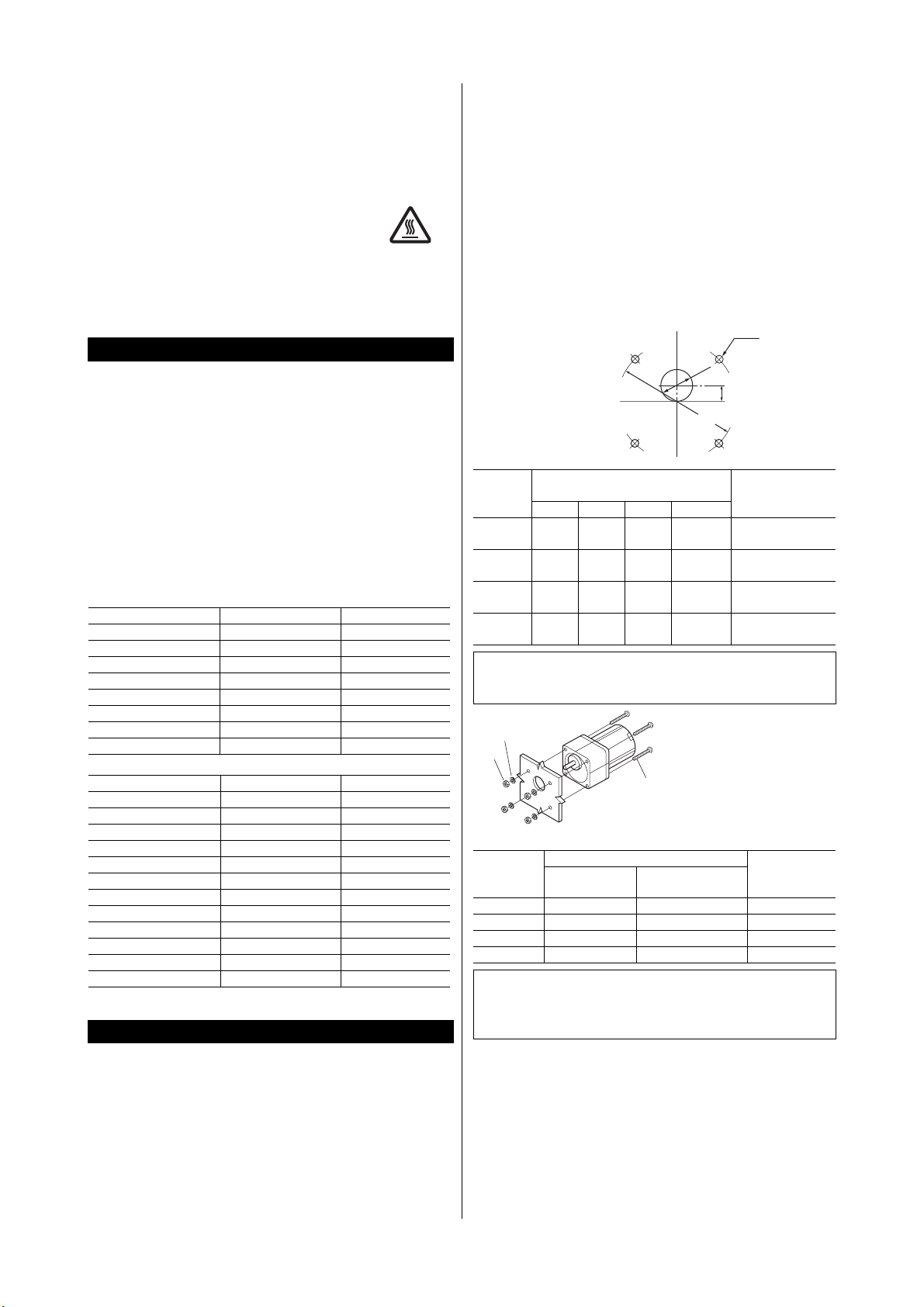
How to install the motor
Drill holes in the mounting plate and fasten the motor to the mounting
plate with screws, nuts, and washers. Be sure that no gaps are left
between the gearhead pilot section of the mounting plate.
The maximum plate thickness applicable when the supplied screws are
used is 10 mm (0.39 in.).
Installation holes
Model
FPW
425
FPW
540
FPW
560
FPW
690
Installation hole dimensions
[mm (in.)]
ØA ØB C 4-ØD
94
(3.70)
104
(4.09)
104
(4.09)
120
(4.72)
34
(1.34)
36
(1.42)
34
(1.34)
42
(1.65)
15
(0.59)
18
(0.71)
18
(0.71)
20
(0.79)
Note
ØB indicates the external dimension of the gearhead boss.
Provide a hole with a sufficient allowance.
Washers
Nuts
Motor
Mounting plate
Screws provided
with motor
Mounting screws
Model
FPW425 M5 P0.8 80 (3.15) 3.8 (33)
FPW540 M6 P1.0 90 (3.54) 6.4 (56)
FPW560 M6 P1.0 90 (3.54) 6.4 (56)
FPW690 M8 P1.25 100 (3.94) 15.5 (137)
Size of mounting screws
Thread size Length [mm (in.)]
Note
Do not disassemble the gearhead from the motor.
Be sure to use the supplied screws and tighten within the
specified torque in order to ensure proper water proof fit.
ØB
ØA
5.5
(0.22)
6.5
(0.26)
6.5
(0.26)
8.5
(0.34)
4-ØD
C
Size of key
[mm (in.)]
4×25
(0.1575×0.984)
4×25
(0.1575×0.984)
5×25
(0.1969×0.984)
6×25
(0.2362×0.984)
Tightening
torque
[N·m (lb-in.)]
2
Page 3

Attaching Load
To shaft of the gearhead has been machined to an outer diameter
tolerance of h7 and is provided with a key slot for connecting the
transmission parts. When connecting the transmission parts, ensure that
the shaft and parts have a clearance fit, and always fix the parallel key to
the output shaft with a screw to prevent the parts from rattling or
spinning.
Note
Do not use excessive force, or hammer the transmission parts
onto the gearmotor shaft as damage may occur.
Mounting the capacitor (only for single-phase motors)
Before mounting the provided capacitor, check
that the capacitor’s capacitance matches that
stated on the motor’s name plate.
Mount the capacitor securely by using M4
screws (not provided).
Ø4.3 mm
(0.169 in.)
Note
Do not let the screw fastening torque exceed 1 N·m (8.8 lb-in)
to prevent damage to the mounting foot.
Mount capacitor at least 10 cm (3.94 in.) away from the
motor. If it is located closer, the life of the capacitor will be
shortened.
Connection and operation
Insulate all the wire connections, such as the connection between the
motor and the capacitor connection.
Ground the motor using a protective grounding wire.
Note
When removing the sheath of the cable, be careful not to
damage the inside lead wire.
Insulation class of this motor is B. Make sure that the motor
case temperature does not exceed 90 °C (194 °F) during
operation of the motor. Operation exceeding case
temperature 90 °C (194 °F) may significantly deteriorate the
coils and ball bearings of the motor and shorten the motor’s
life span. Motor case temperature can be measured by fixing
a thermometer on the motor surface. It can also be
measured using thermo tape or a thermocouple.
To change rotation direction of the single-phase motor, wait
until the motor completely stops. Otherwise its direction may
not change or may take much time to change.
Single-phase motors use a capacitor and keep it connected
even after rotation of the motor has started.
Be sure not to splash water on the cable terminal, otherwise
water could seep inside the motor through the lead wire or
the fabric covering.
Fabric covering
Cable
Keep water from splashing
on this part of the cable
Lead wire
Wiring Diagram
The direction of rotation is as viewed from the side of the motor’s output
shaft. The motor rotates in a clockwise (CW) and counterclockwise
(CCW) direction.
The connection method will vary depending on the gear ratio of the
gearhead.
Motor
25 W
40 W
60 W
90 W
Singlephase
100 V
110 V
115 V
200 V
220 V
230 V
Threephase
200 V
220 V
230 V
type
<Clockwise>
L
N
Capacitor
Green/Yellow
<Counterclockwise>
L
N
Capacitor
Green/Yellow
L1(R)
L2(S)
L3(T)
Green/Yellow
The connection shown in the
figure causes the motor to
rotate clockwise.
To change the direction of
rotation, change any two
connections between R, S
and T.
3 to 18
50 to 180
3 to 9
25 to 60
3 to 9
50 to 180
White
Red
Black
PE
White
Red
Black
PE
Red
White
Black
PE
Motor
CCW
Motor
Motor
Gear ratio
25 to 36
12.5 to 18
75 to 180
12.5 to 36
<Clockwise>
CW
L
N
Capacitor
Green/Yellow
PE
<Counterclockwise>
L
N
Capacitor
Green/Yellow
CW
L1(S)
L2(R)
L3(T)
The connection shown in the
figure causes the motor to
rotate clockwise.
To change the direction of
rotation, change any two
connections between R, S
and T.
PE
Green/Yellow
PE
White
Red
Black
White
Red
Black
Red
White
Black
CW
Motor
CCW
Motor
CW
Motor
A relay box and extension cable for cable are available as an option.
Relay box TB4-0608
Extension cable CC05AC43P (4 wires, 5 m)
CC10AC43P (4 wires, 10 m)
∗ The extension cable has 4-wires; white, gray, black and green/yellow.
When using an extension cable, be sure to connect the red lead wire
of the motor to the gray wire of the cable.
Capacitor connection (only for single-phase motors)
The capacitor internal wiring as follows:
Capacitor terminals are internally electrically connection in twos; A-B and
C-D for easy connection. For
easy to install terminals use
187 series AMP FASTON
terminals (Tyco Electronics
Capacitor cap
AMP).
Use the supplied capacitor cap
to insulate the capacitor
terminal connection.
Capacitor
Note
For lead wire connection, use one lead wire for each individual
terminal.
C
D
A
B
187 series
tab
3
Page 4

r
Time rating
This motor can be operated continuously (continuous rating).
Locked rotor burnout protection
This motor is equipped with the feature listed below to prevent the
motor from burning out as a result of abnormal heating which may be
caused by misapplication.
Thermal protection
“TP” is stamped on the motor nameplate. The motor has an “auto reset”
type thermal protector built into its motor coil. When the motor reaches
a predetermined temperature, the internal thermal protector is activated
and the motor is stopped.
Always turn the power off before performing inspections.
Thermal protector activation range:
Power is turned off at 130±5 °C (266±9 °F)
Power is turned back on at 82±15 °C (180±27 °F)
Troubleshooting
When the motor cannot be operated correctly, refer to the contents
provided in this section and take appropriate action. If the problem
persists, contact your nearest office.
Phenomena Check items
The motor does
not rotate.
Motor sometimes
rotates and stops.
The motor rotates
in the direction
opposite to the
specified direction.
Motor temperature
abnormally high
[Motor case
temperature
exceeds 90 °C
(194 °F)]
• Check the power supply voltage.
• Connect the power supply and the motor
correctly.
• With a single-phase motor, connect the
supplied capacitor correctly.
• If terminal blocks or crimp terminals are used,
check them for poor connection.
• Keep the load at or below the allowable value.
• Connect the power supply and the motor
correctly.
• With a single-phase motor, connect the
supplied capacitor correctly.
• If terminal blocks or crimp terminals are used,
check them for poor connection.
• Connect correctly by referring to “Wiring
diagram.”
• With a single-phase motor, connect the
supplied capacitor correctly.
• The rotating direction of the motor output shaft
may be different from that of the gearhead
output shaft depending on the gear ratio of the
gearhead. Connect correctly by referring to
“Wiring diagram.”
• The rotating direction is indicated as viewed
from the motor output shaft. Check the
reference direction.
• Check the power supply voltage.
• With a single-phase motor, connect the
supplied capacitor correctly.
• Review the ventilation condition.
• Unauthorized reproduction or copying of all or part of this manual is
prohibited.
• Oriental Motor shall not be liable whatsoever for any problems
relating to industrial property rights arising from use of any
information, circuit, equipment or device provided or referenced in
this manual.
• Characteristics, specifications and dimensions are subject to change
without notice.
• While we make every effort to offer accurate information in the
manual, we welcome your input. Should you find unclear
descriptions, errors or omissions, please contact the nearest office.
• is a registered trademark or trademark of
Oriental Motor Co., Ltd., in Japan and other countries.
© Copyright ORIENTAL MOTOR CO., LTD. 2007
• Please contact your nearest Oriental Motor office for further information.
Technical Support Tel:(800)468-3982
A.M.
to 5:00
P.M .
8:30
A.M.
to 5:00
7:30
E-mail: techsupport@orientalmotor.com
www.orientalmotor.com
Headquarters and Düsseldorf Office Tel:0211-52067-00 Fax:0211-52067-099
Munich Office Tel:089-3181225-00 Fax:089-3181225-25
Hamburg Office Tel:040-76910443 Fax:040-76910445
, P.S.T. (M-F)
P.M .
, C.S.T. (M-F)
Tel:01256-347090 Fax:01256-347099
Tel:02-93906346 Fax:02-93906348
Tel:(6745)7344 Fax:(6745)9405
Tel:(03)22875778 Fax:(03)22875528
Tel:66-2-254-6113 Fax:66-2-254-6114
KOREA
Tel:(032)822-2042~3 Fax:(032)819-8745
Tel:01 47 86 97 50 Fax:01 47 82 45 16
Tel:(02)8228-0707 Fax:(02)8228-0708
Headquarters Tokyo, Japan
Tel:(03)3835-0684 Fax:(03)3835-1890
Printed on Recycled Pape
4
 Loading...