

Orientalmotor DSCI26JAM, DSCI315UAM, DSCI26UAM, DSCI315JCM, DSCI425JAM Operating Manual
...Page 1

Speed Control Motor and Controller Package
HM-9306-2
DSC
Series
Standard type
OPERATING MANUAL
Thank you for purchasing an Oriental Motor product.
This Operating Manual describes product handling procedures and safety precautions.
•Please read it thoroughly to ensure safe operation.
•Always keep the manual where it is readily available.
D-loop represents the speed control motor which adopted Oriental
Motor's unique technology.
This product achieves high reliability using closed loop control in
addition to downsize the speed controller by digitizing the phase
control circuit.
Page 2

Table of contents
1 Introduction ..........................................3
2 Safety precautions ...............................4
3 Preparation ..........................................5
3.1 Checking the product ............................. 5
3.2 How to identify the product model .......... 5
3.3 List of combinations ............................... 6
3.4 Names and functions of parts ................ 7
4 Installation ...........................................8
4.1 Location for installation .......................... 8
4.2 Installing the motor ................................. 8
Installing the combination type ................... 8
Removing/Installing the gearhead.............. 9
Installing the round shaft type .................... 9
For the motor equipped with
cooling fan (90 W) ...................................... 9
4.3 Installing a load .................................... 10
4.4 Permissible radial load and
permissible axial load ........................... 10
4.5 Installing the speed controller .............. 11
4.6 Installing the capacitor ......................... 12
4.7 Installing an external potentiometer ..... 12
5 Connection ........................................13
5.1 Connecting method .............................. 13
5.2 Connecting the AC power supply and
capacitor ............................................... 14
5.3 Connecting the motor and
speed controller .................................... 14
5.4 Grounding ............................................ 15
5.5 Connecting the control DC power
supply and I/O signals .......................... 15
5.6 Connection example for I/O signals and
programmable controller ...................... 17
6 Operation ...........................................18
6.1 Power ON ............................................. 18
Test operation........................................... 18
6.2 Starting, stopping ................................. 19
6.3 Setting the rotation speed .................... 19
Setting method using the
operation panel ........................................ 20
Remote setting method ............................ 20
6.4 Setting the acceleration time and
deceleration time .................................. 21
6.5 Motor rotation direction ........................ 21
6.6 Timing chart .......................................... 22
6.7 Short time cycle operation and
braking current ..................................... 22
6.8 Operating in two or more speeds
(multi-speed operation) ........................ 23
6.9 Adjusting the rotation speed of two
or more motors by a single speed setter
(multi-motor control) ............................. 24
7 Function .............................................25
7.1 Functions list ........................................ 25
7.2 Operation panel transitions .................. 26
7.3 Items which can be monitored ............. 28
7.4 Setting the operation data .................... 28
7.5 Setting the parameters ......................... 29
Parameter list ........................................... 29
Displayed digit number when setting the
speed reduction ratio or speed increasing
ratio .......................................................... 30
How to calculate the speed reduction ratio
when displaying the conveyor transfer
speed ....................................................... 30
Limiting the setting range of the rotation
speed ....................................................... 30
Description of I/O signals which can be
assigned ................................................... 31
7.6 Prohibiting data editing ......................... 31
8 Alarm .................................................32
8.1 Alarm .................................................... 32
8.2 Warning ................................................ 34
9 Troubleshooting and remedial
actions ...............................................35
10 Inspection ..........................................36
11 Standard and CE Marking .................37
11.1 Standard and CE Marking .................... 37
11.2 Installing and wiring in compliance with
EMC Directive ...................................... 38
12 General specications .......................40
13 Accessories (sold separately) ...........41
−2−
Page 3

1 Introduction
Note
Note
Before use
Only qualied and educated personnel should work with the product.
Use the product correctly after thoroughly reading the section "2 Safety precautions" on p.4.
The items under
product.
The product described in this manual has been designed and manufactured to be incorporated in general industrial
equipment. Do not use for any other purpose. Oriental Motor Co., Ltd. is not responsible for any damage caused
through failure to observe this warning.
Overview of the product
The DSC Series is a speed control motor and controller package equipped with closed loop control system which
achieves high reliability.
This product controls the motor rotation speed by constantly utilizing feedback from the tachogenerator built in the
AC motor so that the set rotation speed can be maintained even if a load is uctuated.
It is supplied as a package consisting of a speed controller displaying the motor rotation speed and a dedicated motor
pre-assembled with a high-performance gearhead.
The speed controller can be operated with selecting maximum 4 operation data, in addition to equipping convenient
functions such as speed display based on the application, various alarms to detect the motor malfunction and others.
contain important handling instructions that the user should observe to ensure safe use of the
is described in the related handling items.
Introduction
−3−
Page 4
Safety precautions
Warning
Caution
2 Safety precautions
The precautions described below are intended to prevent danger or injury to the user and other personnel through safe,
correct use of the product. Use the product only after carefully reading and fully understanding these instructions.
Handling the product without observing the instructions that accompany a “Warning” symbol may result in
serious injury or death.
General
•Do not use the product in explosive or corrosive environments, in
the presence of ammable gases, locations subjected to splashing
water, or near combustibles. Doing so may result in re, electric
shock or injury.
•Only qualied and educated personnel should be allowed to perform
installation, connection, operation and inspection/troubleshooting of
the product. Handling by unqualied and uneducated personnel may
result in re, electric shock, or injury.
•Do not transport, install, connect or inspect the product while the
power is supplied. Always turn the power off before carrying out
these operations. Failure to do so may result in electric shock.
•The terminals on the speed controller front panel marked with
symbol indicate the presence of high voltage. Do not touch
the CN1 and CN3 while the power is ON. Doing so may result in
re or electric shock.
Installation
•The motor is ClassⅠ equipment.
When installing the motor, ground the Protective Earth Terminal of
the motor. Failure to do so may result in electric shock.
•Install the motor and speed controller in an enclosure. Failure to do
so may result in electric shock or injury.
Handling the product without observing the instructions that accompany a “Caution” symbol may result in
injury or property damage.
Connection
•For the AC power supply voltage of the speed controller, use the
same power supply voltage as the motor specication. Failure to do
so may result in re or damage to equipment.
•The speed controller has no built-in fuse for overcurrent protection.
Be sure to connect a device for fuse in the power input line. Failure
to do so may result in re.
•Securely connect and ground in accordance with the connection
examples. Failure to do so may result in re or electric shock.
•Do not forcibly bend, pull or pinch the cable. Doing so may cause
re or electric shock.
•Be sure to observe the specied cable sizes. Use of unspecied cable
sizes may result in re.
•Insulate the connection terminals of the supplied capacitor using the
supplied capacitor cap. Failure to do so may result in electric shock.
Maintenance and inspection
•Do not touch the connector of the speed controller immediately
after the power is turned off (for a period of 1 minute). The residual
voltage may cause electric shock.
Disassembly and modication
•Do not disassemble or modify the motor and speed controller.
This may cause electric shock or injury.
General
•Do not use the motor and speed controller beyond their
specications. Doing so may result in electric shock, injury or
damage to equipment.
•Do not carry the motor by holding the motor output shaft or motor
cable. Doing so may result in injury.
•If an alarm of the speed controller is generated, rst remove the
cause and then reset the alarm. Failure to do so may result in injury
or damage to equipment.
•Do not use the product in elevating applications (vertical drives).
Doing so may result in injury or damage to equipment.
Installation
•Keep the area around the motor and speed controller free of
combustible materials. Failure to do so may result in re or a skin
burn(s).
•Do not leave anything around the motor and speed controller that
would obstruct ventilation. Doing so may result in damage to
equipment.
•Securely install the motor and speed controller to the mounting plate
and DIN rail respectively. Inappropriate installation may cause the
motor and speed controller to detach and fall, resulting in injury or
equipment damage.
Connection
•Do not wire the electromagnetic contactor or power relay between
the motor and speed controller. To switch the rotation direction using
the electromagnetic contactor may cause damage to equipment.
•Be sure to ground the motor and speed controller to prevent them
from being damaged by static electricity. Failure to do so may result
in damage to equipment.
Operation
•Use a motor and speed controller only in the specied combination.
An incorrect combination may cause a re.
•Provide an emergency stop device or emergency stop circuit external
to the equipment so that the entire equipment will operate safely in
the event of a system failure or malfunction. Failure to do so may
result in injury.
•Immediately when trouble has occurred, stop running and turn
off the speed controller power. Failure to do so may result in re,
electrical shock or injury.
•Do not touch the rotating part (output shaft) while operating the
motor. Doing so may result in injury.
•The motor surface temperature may exceed 70 °C
(158 °F) even under normal operating conditions. If
the operator is allowed to approach a running motor,
attach a warning label as shown in the gure in a
conspicuous position. Failure to do so may result in
skin burn(s).
Warning label
Maintenance and inspection
•Conduct the insulation resistance measurement or dielectric strength
test separately on the motor and speed controller. Conducting while
the motor and speed controller are connected may result in damage
to equipment.
Disposal
•To dispose of the motor and speed controller, disassemble it into
parts and components as much as possible and dispose of individual
parts/components as industrial waste.
−4−
Page 5
3 Preparation
3.1 Checking the product
Verify that the items listed below are included. Report any missing or damaged items to the branch or sales ofce
from which you purchased the product.
Verify the model number of the purchased product against the number shown on the package label.
Check the model number of the motor, gearhead and speed controller against the number shown on the nameplate.
Motor ......................................................... 1
(The combination types come with the motor and gearhead
pre-assembled)
Speed controller ........................................ 1
Capacitor .................................................. 1 pc
Capacitor cap ............................................ 1 pc
Connection cable ...................................... 1 pc
(Only models with a supplied connection cable)
External potentiometer .............................. 1 pc
(Only models with a supplied external potentiometer)
OPERATING MANUAL (this document) ... 1 pc
unit
unit
[Supplied with only the models of the combination type]
Hexagonal socket head screw set........1 set
(Hexagonal socket head screw, at washer,
spring washer, 4 pieces each, parallel key 1 piece)
Preparation
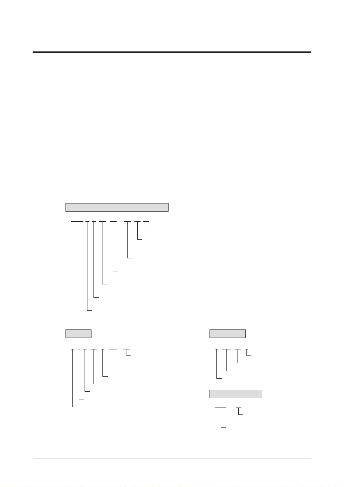
3.2 How to identify the product model
Motor and speed controller package
DSC I 4 25 JA - 50 -3 V
Blank: Without a supplied external potentiometer
V: External potentiometer (supplied)
Number: Length (m) of a supplied connection cable
-1: 1 m (3.3 ft.), -2: 2 m (6.6 ft.), -3: 3 m (9.8 ft.)
Blank: Without a supplied connection cable
Number: Gear ratio for combination type
A: Round shaft type
Power supply voltage JA: Single-phase 100 V UA: Single-phase 110 V, 115 V
JC: Single-phase 200 V EC: Single-phase 220 V, 230 V
Output power 6: 6 W, 15: 15 W, 25: 25 W
40: 40 W, 60: 60 W, 90: 90 W
Frame size 2: 60 mm (2.36 in.) sq. 3: 70 mm (2.76 in.) sq.
4: 80 mm (3.15 in.) sq. 5: 90 mm (3.54 in.) sq.
Motor Type I: Induction Motor
Series name
Motor
4 I K 25 U GV - JA
Power supply voltage
Pinion shaft type: GV, GVH, GVR
Round shaft type: A
U: For the motor and speed controller package
Output power
K䊡 Series
Induction Motor
Frame size
Gearhead
4 GV 50 B
Identification code
Gear ratio
Pinion type
Frame size
Speed controller
DSC - U
For the motor and speed
controller package
Series name
−5−
Page 6

Preparation
3.3 List of combinations
Model names for motor, gearhead and speed controller are shown below.
•Enter the gear ratio in the box (o) within the model name for the combination type. Enter "A" in the case of the
round shaft type.
For the motor model, the GV,
round shaft type.
•Enter the cable length (-1, -2, -3) in the box () within the model name when the connection cable is supplied.
•Add "V" to the end of the model name when the external potentiometer is supplied.
GVH
or
which represents the gear type is replaced with "A" in the case of the
GVR
Motor
output power
6 W
15 W
25 W
40 W
60 W
90 W
Power supply voltage Model Motor model
Single-phase 100 V
Single-phase 110/115 V
Single-phase 200 V
Single-phase 220/230 V
Single-phase 100 V
Single-phase 110/115 V
Single-phase 200 V
Single-phase 220/230 V
Single-phase 100 V
Single-phase 110/115 V
Single-phase 200 V
Single-phase 220/230 V
Single-phase 100 V
Single-phase 110/115 V
Single-phase 200 V
Single-phase 220/230 V
Single-phase 100 V
Single-phase 110/115 V
Single-phase 200 V
Single-phase 220/230 V
Single-phase 100 V
Single-phase 110/115 V
Single-phase 200 V
Single-phase 220/230 V
DSCI26JA-
DSCI26UA-
DSCI26JC-
DSCI26EC-
DSCI315JA-
DSCI315UA-
DSCI315JC-
DSCI315EC-
DSCI425JA-
DSCI425UA-
DSCI425JC-
DSCI425EC-
DSCI540JA-
DSCI540UA-
DSCI540JC-
DSCI540EC-
DSCI560JA-
DSCI560UA-
DSCI560JC-
DSCI560EC-
DSCI590JA-
DSCI590UA-
DSCI590JC-
DSCI590EC-
o
o
o
o
o
o
o
o
o
o
o
o
o
o
o
o
o
o
o
o
o
o
o
o
2IK6UGV-JA
2IK6UGV-UA
2IK6UGV-JC
2IK6UGV-EC
3IK15UGV-JA
3IK15UGV-UA
3IK15UGV-JC
3IK15UGV-EC
4IK25UGV-JA
4IK25UGV-UA
4IK25UGV-JC
4IK25UGV-EC
5IK40UGV-JA
5IK40UGV-UA
5IK40UGV-JC
5IK40UGV-EC
5IK60UGVH-JA
5IK60UGVH-UA
5IK60UGVH-JC
5IK60UGVH-EC
5IK90UGVR-JA
5IK90UGVR-UA
5IK90UGVR-JC
5IK90UGVR-EC
Gearhead
model
2GVoB
3GVoB
4GVoB
5GVoB
5GVHoB
5GVRoB
Speed controller
model
DSC-U
−6−
Page 7
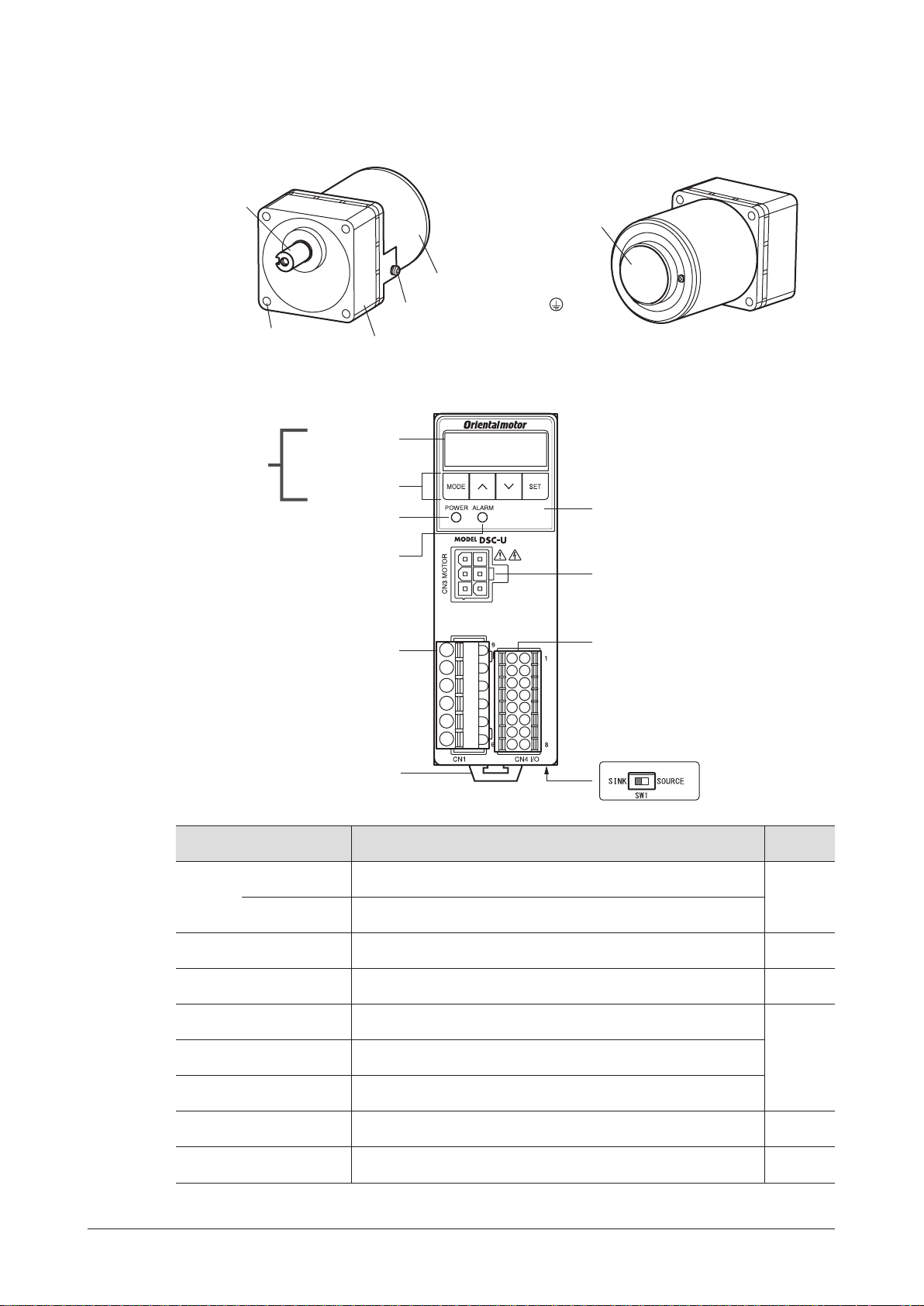
3.4 Names and functions of parts
Motor
Output shaft
Preparation
Tachogenerator
Mounting holes
(four locations)
Gearhead
Motor
Protective Earth Terminal
Rear view of the motor
Speed controller
Display
Operation panel
Operation keys
POWER LED
(Green)
ALARM LED
(Red)
Main circuit connector
(CN1)
Protective film
(Use after removing the protective film.)
Motor connector
(CN3)
Control circuit connector
(CN4)
Name Description
Display
Operation
panel
(4-digit LED)
Operation keys
POWER LED
(Green)
ALARM LED
(Red)
Motor connector
(CN3)
Main circuit connector
(CN1)
Control circuit connector
(CN4)
Sink logic / Source logic
select switch (SW1)
DIN lever
Sink logic/Source logic
select switch (SW1)
DIN lever
Reference
The rotation speed, parameter, alarm and others are shown on the
display.
These keys are used to switch the operation mode, set the operation
data or change the parameter.
This LED is lit while the AC power is supplied to the speed controller. p.18
This LED blinks while an alarm generates. p.32
Connects the motor connector.
Connects the AC power supply, capacitor and FG.
Connects the control DC power supply and I/O signals.
This switch is used for switching the input signal between sink logic
and source logic modes.
Mounts the speed controller to a DIN rail.
The speed controller can be mounted using screws.
page
p.26
p.13
p.17
p.11
−7−
Page 8
Installation
MotorGearhead
4 Installation
This chapter explains the installation location and installation methods.
4.1 Location for installation
The motor and speed controller described in this manual have been designed and manufactured to be incorporated in general
industrial equipment. Install them in a well-ventilated location that provides easy access for inspection.
•Inside an enclosure that is installed indoors
•Operating ambient temperature
Motor:
The operating ambient temperature varies depending on the
AC input voltage of the motor.
100 VAC and 200 VAC types:
−10 to +50 ˚C [+14 to +122 ˚F] (non-freezing)
110/115 VAC and 220/230 VAC types:
−10 to +40 ˚C [+14 to +104 ˚F] (non-freezing)
Speed controller
0 to +50 °C [+32 to +122 °F] (non-freezing)
•Operating ambient humidity 85% or less (non-condensing)
•Area that is free of explosive atmosphere or toxic gas
(such as sulfuric gas) or liquid
•Area not stored combustible materials
•Area not exposed to direct sun
•Area free of excessive amount of dust, iron particles or the like
•Area not subject to splashing water (rain, water droplets), oil
(oil droplets) or other liquids
•Area free of excessive salt
•Area not subject to continuous vibration or excessive shocks
•Area free of excessive electromagnetic noise (from welders,
power machinery, etc.)
•Area free of radioactive materials, magnetic elds or vacuum
•Altitude: Up to 1000 m (3300 ft.) above sea level
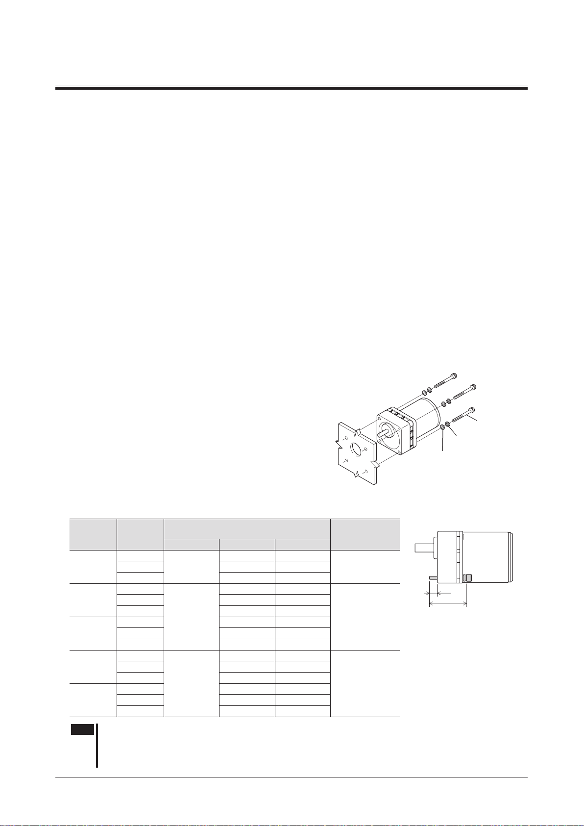
4.2 Installing the motor
Installing the combination type
Drill tapped holes in the mounting plate and secure the product with the
supplied hexagonal socket head screw set through four mounting holes.
Install it so that no gaps remain between the gearhead mounting surface
and mounting plate.
•Supplied hexagonal socket head screw set
(Hexagonal socket head screws, washers, spring washers 4 pieces each)
Gearhead
model
2GVoB
3GVoB
4GVoB
5GVoB
5GVHoB
5GVRoB
Gear ratio
5 to 25
150 to 360 60 (2.36) 8 (0.31)
5 to 25
30 to 120 65 (2.56) 12 (0.47)
150 to 360 70 (2.76) 12 (0.47)
5 to 25 60 (2.36) 9 (0.35)
30 to 120 65 (2.56) 9 (0.35)
150 to 360 70 (2.76) 9 (0.35)
5 to 18
25 to 100 85 (3.35) 16 (0.63)
120 to 300 90 (3.54) 15 (0.59)
5 to 15 70 (2.76) 14 (0.55)
18 to 36 85 (3.35) 16 (0.63)
50 to 180 95 (3.74) 14 (0.55)
Hexagonal socket head screw
(Material: Stainless steel)
Screw size L1 [mm (in.)] L2 [mm (in.)]
50 (1.97) 7 (0.28)
M4
60 (2.36) 12 (0.47)
M6
70 (2.76) 14 (0.55)
M8
Gearhead
Tightening torque
[N·m (lb-in)]
1.4 (12)30 to 120 55 (2.17) 8 (0.31)
5.0 (44)
12.0 (106)
Motor
Mounting plate
Washer
L2
L1
Spring
washer
Hexagonal
socket head
screw
−8−
Note
On rare occasions, a small amount of grease may ooze out from the gearhead. If there is a concern over
possible environmental damage resulting from the leakage of grease, provide an oil tray or similar oil
catching mechanism in order not to cause a secondary damage.
Oil leakage may lead to problems in the customer’s equipment or products.
Page 9
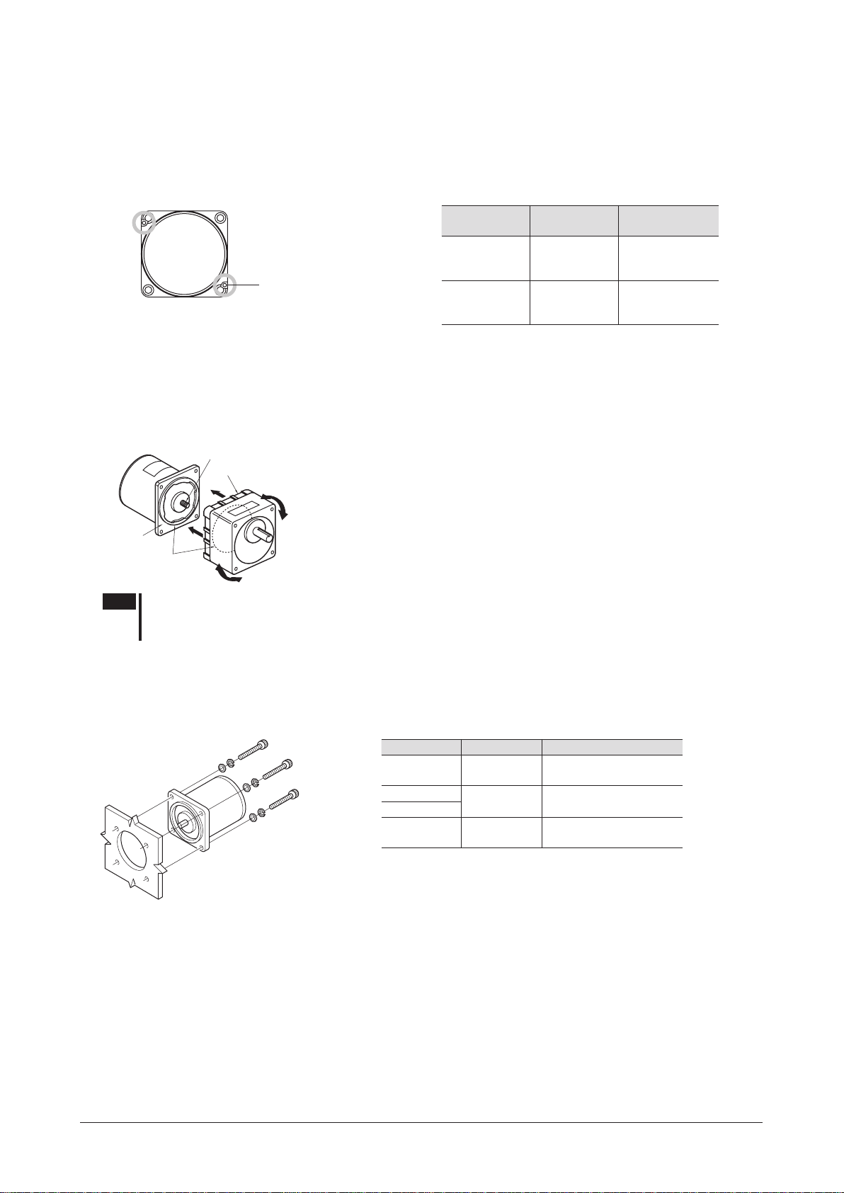
Removing/Installing the gearhead
Illustration shows the view from motor case side.
Output shaft (pinion) of motor
The gearhead or the outlet position of the motor lead wires can be changed.
•Removing the gearhead from the motor
Remove the gearhead by unscrewing the hexagonal socket-head screws holding the gearhead to the motor
(2 locations).
Installation
Hexagonal socket-head screw
(2 locations)
Gearhead
model
2GVoB
3GVoB
4GVoB
5GVoB
5GVHoB
5GVRoB
Screw size
M2.6 0.4 (3.5)
M3 0.6 (5.3)
Tightening torque
[N·m (lb-in)]
•Combining the gearhead to the motor
Using the pilot sections of the motor and gearhead as guides, slowly rotate it clockwise/counterclockwise to prevent the pinion
of the motor output shaft from contacting the side panel or gear of the gearhead. Also conrm that no gaps remain between the
motor and gearhead.
An O-ring is attached to the ange of the motor. Do not pinch the O-ring when assembling the motor and gearhead. Pinching the
O-ring causes a grease leak from the gearhead.
Motor
Pilot end face
Flange
Pilot section
Note
Do not forcibly assemble the motor and gearhead. Also, do not let metal objects or other foreign
matters enter the gearhead. The pinion or gear of the motor output shaft may be damaged,
resulting in noise or shorter service life.
Gearhead
Installing the round shaft type
Drill holes in the mounting plate, and secure the motor using the hexagonal socket head screws (not supplied) through four
mounting holes.
Install it so that no gaps remain between the motor mounting surface and mounting plate.
Motor
Mounting plate
For the motor equipped with cooling fan (90 W)
When installing a motor with cooling fan onto a device, leave 10 mm (0.39 in.) or more behind the fan cover or open a ventilation
hole so that the cooling inlet on the back of the motor cover is not blocked. This is common to both the combination type and
round shaft type.
Motor model Screw size Tightening torque
2IK
3IK
4IK
5IK
The brackets [ ] indicate the value for stainless steel.
M4
M5
M6
1.8 N·m (15.9 lb-in)
[1.4 N·m (12 lb-in)]
3.8 N·m (33 lb-in)
[3.0 N·m (26 lb-in)]
6.4 N·m (56 lb-in)
[5.0 N·m (44 lb-in)]
−9−
Page 10
Installation
Fixed screw
Transmission parts
Radial load
4.3 Installing a load
When installing a load on the motor (gearhead), pay attention to the following points.
•Align the centerline of the motor output shaft (gearhead output shaft) with the centerline of the load.
•A key slot is provided on the output shaft of each combination type parallel shaft gearhead.
Form a key slot on the load side and secure the load using the supplied parallel key.
Note
•When coupling the motor (gearhead) with a load, pay attention to centering, belt tension,
parallelism of pulleys, etc. Also, rmly secure the tightening screws of the coupling or pulleys.
•When installing a load, do not damage the motor output shaft (gearhead output shaft) or
bearing. Forcing in the load by driving it with a hammer, etc., may break the bearing. Do not
apply any excessive force to the output shaft.
•Do not modify or machine the motor (gearhead) output shaft. The bearing may be damaged or
motor (gearhead) may break.
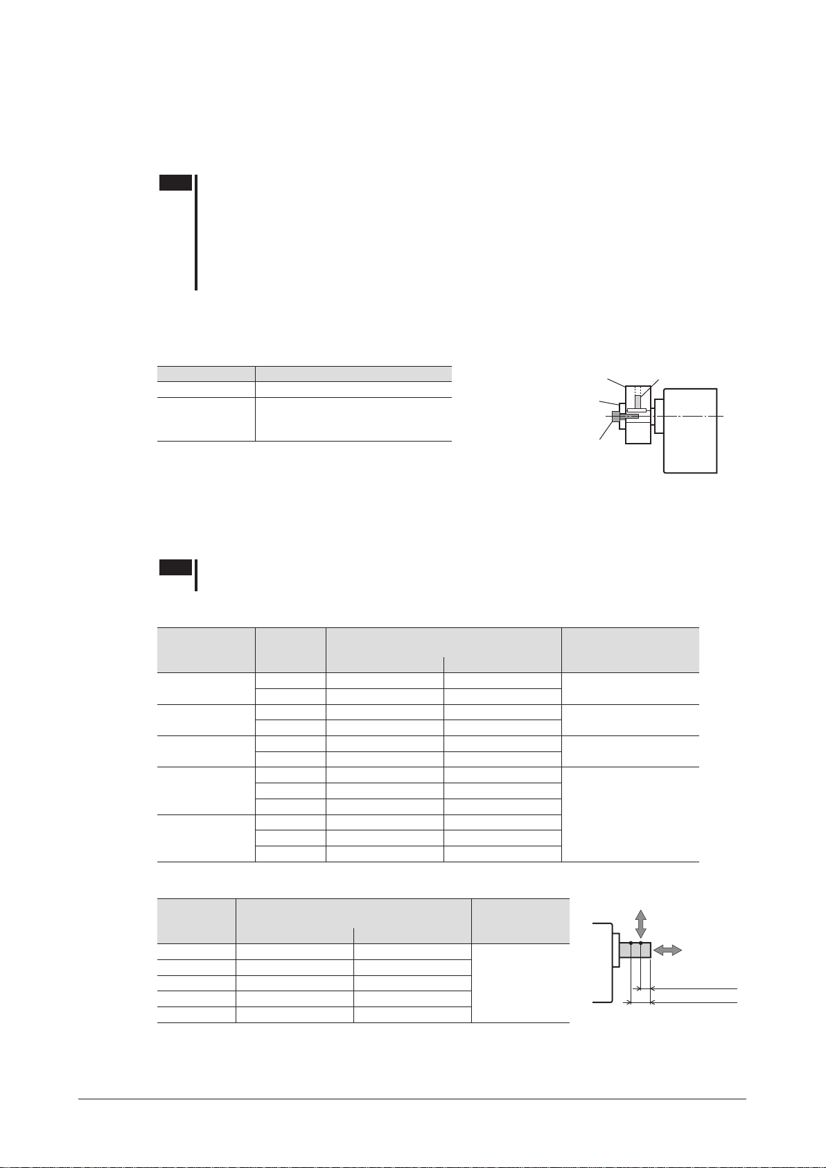
•When using the output shaft end tapped hole of a gearhead
Use a tapped hole provided at the end of the output shaft as an auxiliary means for preventing the transfer mechanism
from disengaging.
Gearhead model Output shaft end tapped hole
4GVoB
5GVoB
5GVHoB
5GVRoB
(The output shaft end tapped hole is not provided for the
*
2GVoB
and
M5, Effective depth 10 mm (0.39 in.)
M6, Effective depth 12 mm (0.47 in.)
types.)
3GVoB
Spacer
Screw
4.4 Permissible radial load and permissible axial load
The radial load and the axial load on the output shaft of the motor (gearhead) must be kept under the permissible
values listed below.
Note
Failure due to fatigue may occur when the motor (gearhead) bearings and output shaft are subject
to repeated loading by a radial or axial load that is in excess of the permissible limit.
Combination type
Permissible radial load [N (lb.)]
Gearhead model Gear ratio
2GVoB
3GVoB
4GVoB
5GVoB
5GVHoB
5GVRoB
5 to 25 150 (33) 200 (45)
30 to 360 200 (45) 300 (67)
5 to 25 200 (45) 300 (67)
30 to 360 300 (67) 400 (90)
5 to 25 300 (67) 350 (78)
30 to 360 450 (101) 550 (123)
5 to 9 400 (90) 500 (112)
12.5 to 18 450 (101) 600 (135)
25 to 300 500 (112) 700 (157)
5 to 9 400 (90) 500 (112)
12.5 to 18 450 (101) 600 (135)
25 to 180 500 (112) 700 (157)
Distance from tip of gearhead output shaft
10 mm (0.39 in.) 20 mm (0.79 in.)
Round shaft type
Permissible radial load [N (lb.)]
Motor model
2IK6
3IK15
4IK25
5IK40
5IK60, 5IK90
Minimize the axial load. If an axial load must be applied, do not let it exceed one-
*
half the motor’s mass.
Distance from output shaft end of the motor
10 mm (0.39 in.) 20 mm (0.79 in.)
50 (11.2) 110 (24)
40 (9) 60 (13.5)
90 (20) 140 (31)
140 (31) 200 (45)
240 (54) 270 (60)
Permissible
Not to exceed
one-half the
motor’s dead
axial load
[N (lb.)]
weight
Permissible axial load
*
[N (lb.)]
40 (9)
80 (18)
100 (22)
150 (33)
Axial load
10 mm (0.39 in.)
20 mm (0.79 in.)
Distance from output
shaft end
−10−
Page 11
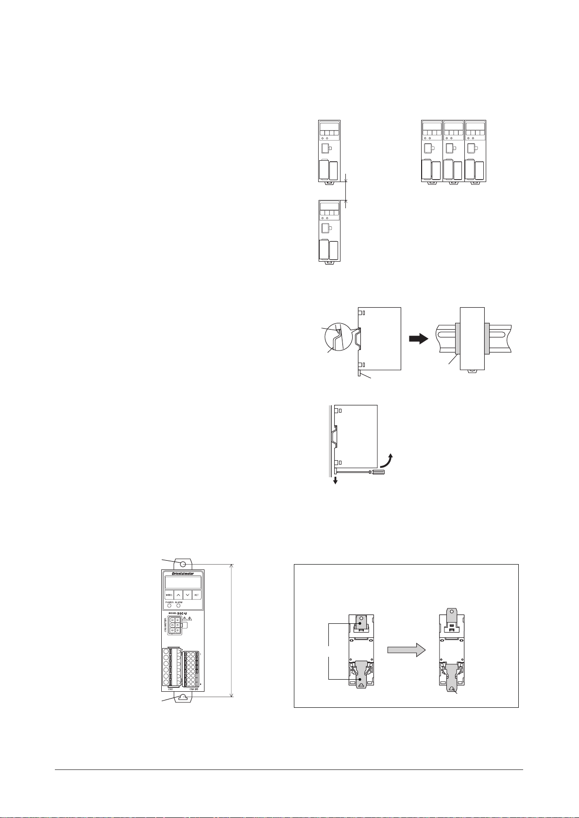
4.5 Installing the speed controller
• Vertical direction
• Horizontal direction
Mounting hole
The speed controller is designed so that heat is dissipated via air convection. Provide spaces so that the speed
controller can be ventilated well through its top and bottom vent holes.
Installation direction
When installing speed controllers, provide a
clearance of at least 25 mm (0.98 in.) in the vertical
direction between the speed controller and enclosure
or other equipment within the enclosure.
When installing two or more speed controllers in
parallel, it is possible to install them closely in the
horizontal direction.
Installation method
•Mounting to DIN rail
Use a DIN rail 35 mm (1.38 in.) wide to mount the
speed controller.
Pull down the DIN lever of the speed controller
until it locks, and push in the speed controller with
hanging the hook at the rear to the DIN rail, and
then lift the DIN lever. After installation, secure
the both sides of the speed controller with the end
plate that the customer provides.
Installation
25 mm (0.98 in.)
or more
Hook
DIN rail
End plate
DIN lever
Removing from DIN rail
Pull the DIN lever down until it locks using a at tip
screwdriver, and lift the bottom of the speed controller to
remove it from the rail.
Use force of about 10 to 20 N (2.2 to 4.5 lb.) to pull the
DIN lever to lock it.
Excessive force may damage the DIN lever.
•Installing with screws
Install the speed controller through the mounting holes using two screws (M4: not supplied).
[Tightening torque: 0.7 N·m (6.1 lb-in)]
Use screws and washers, which sizes are Ø10 mm or less, to secure the speed controller.
When installing with screws, pull up and down the upper
and lower levers on the rear side of the speed controller
respectively before doing so.
Pull the levers
Levers
111 mm (4.37 in.)
Mounting hole
Mounting hole
−11−
Page 12
Installation
• Reference mounting hole dimensions
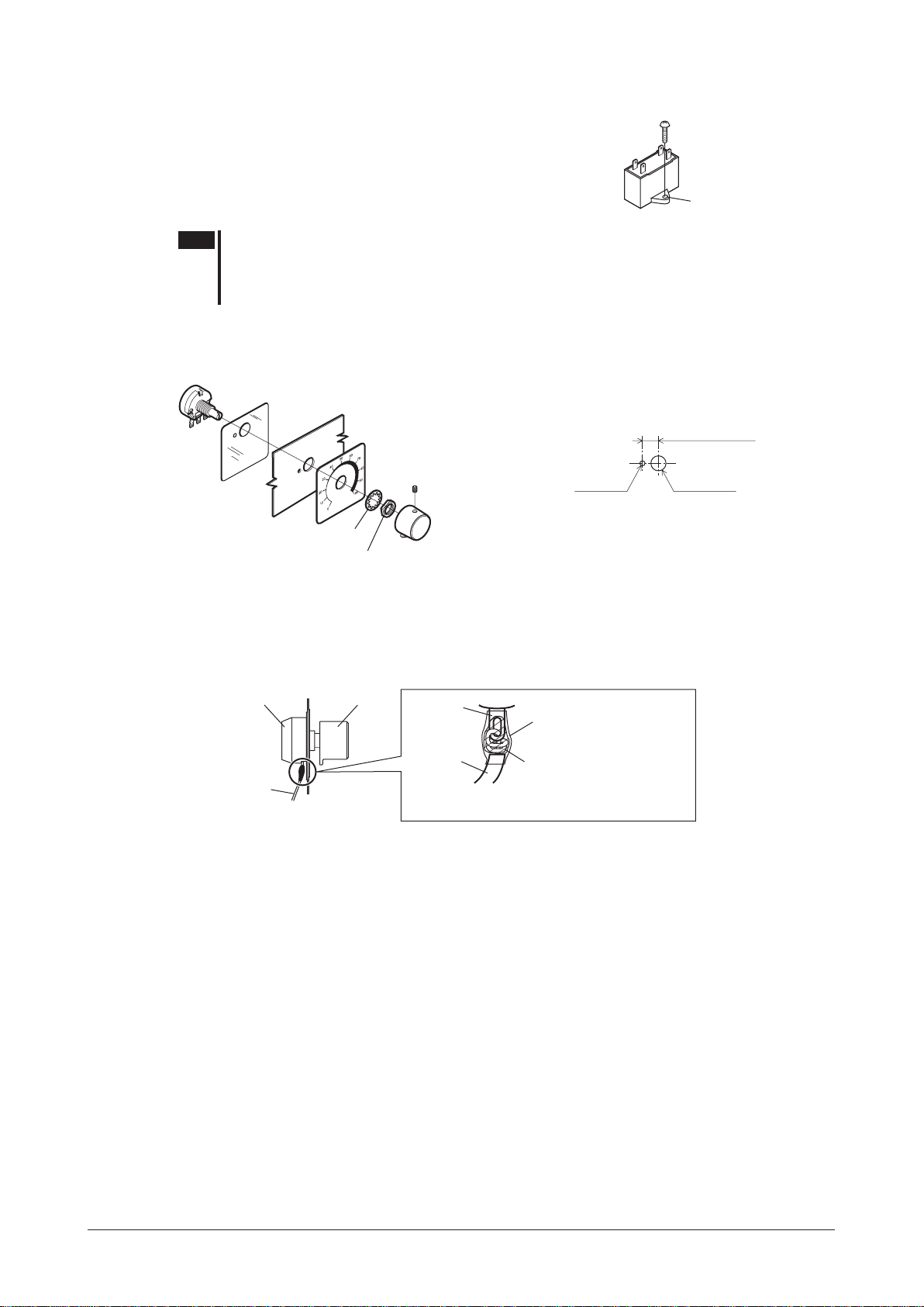
4.6 Installing the capacitor
Mount the capacitor securely using M4 screw (not provided).
Ø4.3 mm
(0.169 in.)
Note
•Do not let the screw fastening torque exceed 1 N·m (8.8 lb-in) to prevent damage to the
mounting foot.
•Install the capacitor apart from the motor. If it is located closer, the capacitor life may be
shortened due to the heat of the motor.
4.7 Installing an external potentiometer
When using an external potentiometer (supplied or sold separately:
Variable resistor
Soldering the variable resister terminals and the lead wires
Cover a heat-shrinkable tube over the soldered part to insulate.
Soldering condition: 235 °C (455 ˚F), less than 5 sec
Insulation sheet
Mounting plate
Dial plate
Setscrew (M4)
Tightening torque:
0.4 N·m (3.5 lb-in)
Dial
Toothed washer
Nut
Tightening torque:
0.45 N·m (3.9 lb-in)
PAVR-20KZ
), install it as shown in the gure.
[Unit: mm (in.)]
Ø3 (0.12)
7.5
±0.4 (0.3±0.02)
Ø10 (0.39)
DialVariable resistor
Lead wire
Terminal
Lead wire
Refer to p.20 for connection of the external potentiometer.
Heat-shrinkable tube
Solder
(Pass the lead wire through
the terminal hole and give it
two or three turns.)
−12−
Page 13
5 Connection
Speed controllerMotor
This chapter explains how to connect the speed controller, power supply, motor and others.
When operating a motor, be sure to connect the control DC power supply in addition to the AC power supply.
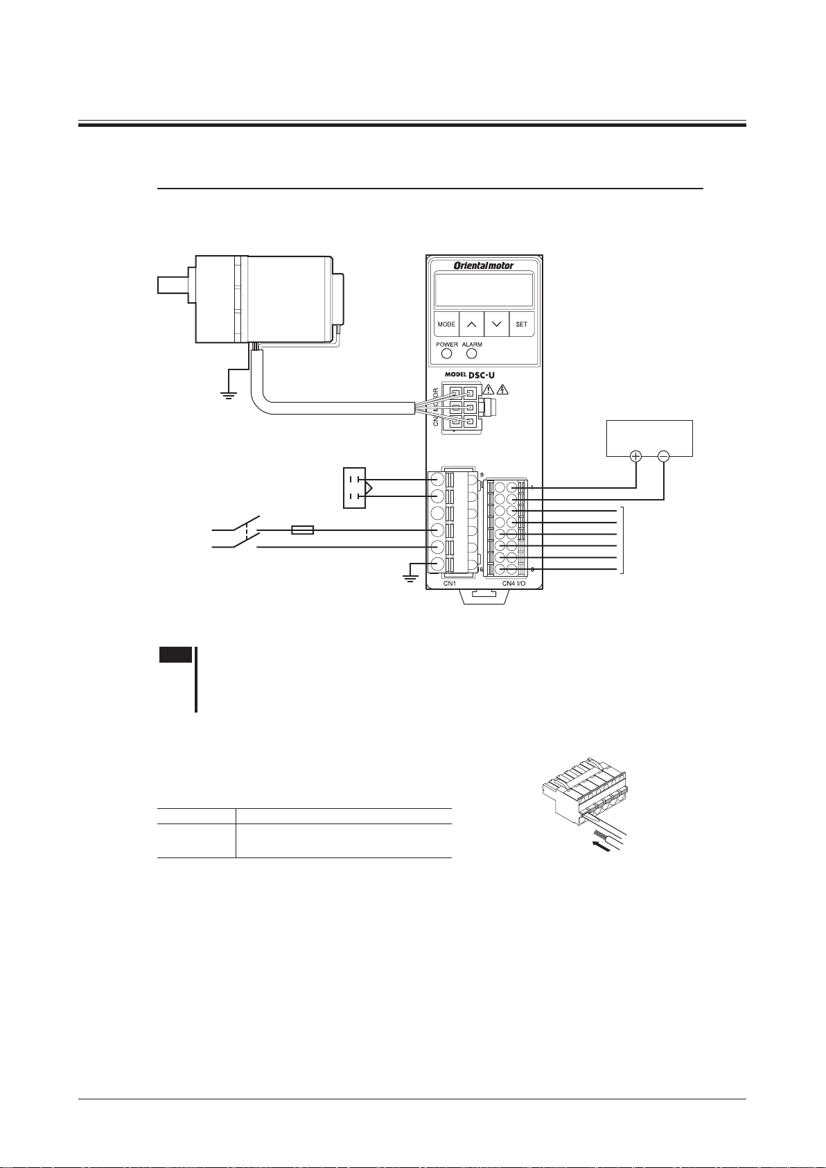
5.1 Connecting method
Grounding
Connection
Control DC power supply
24 VDC±10%
150 mA or more
Capacitor
AC power
supply
Single-phase 100 V 50/60 Hz
Single-phase 110/115 V 60 Hz
Single-phase 200 V 50/60 Hz
Single-phase 220/230 V 50/60 Hz
Note
•For the AC power supply voltage of the speed controller, be sure to use the same power supply
Fuse
L (Live)
N (Neutral)
Grounding
voltage as the motor specication.
•Ensure that the connector plugged in securely. Insecure connection may cause malfunction or
damage to the motor or speed controller.
How to wiring the CN1 and CN4 connectors
Insert the lead wire while pushing the button of the orange color with a
screwdriver.
Manufacturer PHOENIX CONTACT GmbH & Co. KG
Model
CN1: FKCT 2,5/6-ST-5,08
CN4: DFMC 1,5/8-ST-3,5
Connect the I/O signals
to CN4 on the speed
controller
Refer to p.15
−13−
Page 14
Connection
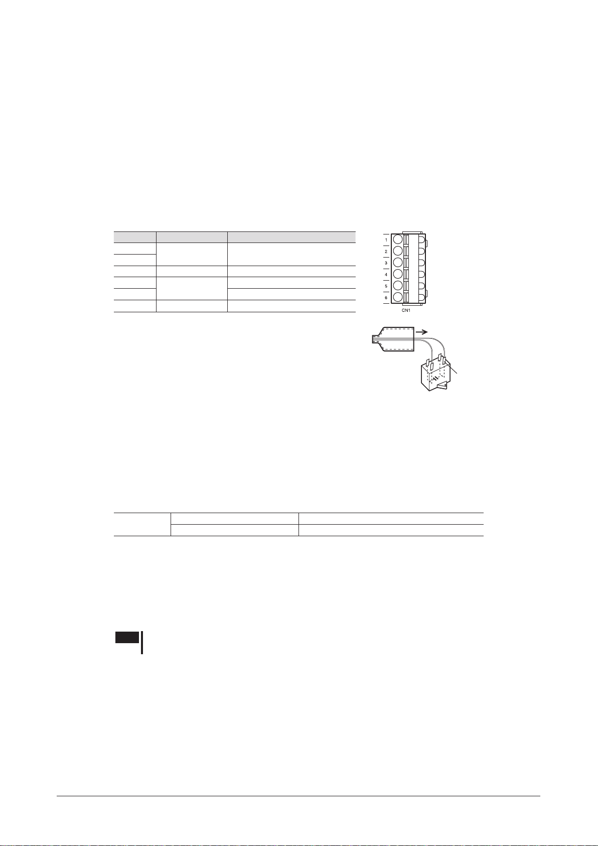
5.2 Connecting the AC power supply and capacitor
Connect the AC power supply and capacitor to the CN1 on the speed controller.
•Applicable cable size: AWG18 to 14 (0.75 to 2.0 mm
AWG20 to 14 (0.5 to 2.0 mm
*
•Lead wire strip length: 10 mm (0.39 in.)
If crimp terminals are used, select the following terminals.
Manufacturer: PHOENIX CONTACT GmbH & Co. KG
Model: AI 0,5-10 [Conductor cross-sectional area: 0.40 to 0.65 mm
AI 0,75-10 [Conductor cross-sectional area: 0.65 to 0.82 mm
AI 1-10 [Conductor cross-sectional area: 0.82 to 1.2 mm
AI 1,5-10 [Conductor cross-sectional area: 1.25 to 1.8 mm
AI 2,5-10 [Conductor cross-sectional area: 2.0 to 3.0 mm
CN1 pin assignments
Pin No. Connection Description
1
Capacitor Connects the capacitor.
2
3 N.C. Not connected.
4
AC power supply
5 Connects a neutral wire.
6 FG Connects a grounding wire.
Connects a live wire.
2
)
*
2
) for capacitor connection
2
(AWG20)]
2
(AWG18)]
2
(AWG18)]
2
(AWG16)]
2
For capacitor connection
*
(AWG14)]
*
Connecting the capacitor
There are four terminals in the supplied capacitor, and the
terminals A-B and C-D are internally connected as shown in the
gure.
Connect either of the terminals A or B and either of the terminals
C or D to the speed controller.
Use the supplied capacitor cap to insulate the capacitor terminal
connection.
Connecting the earth leakage breaker
Install an earth leakage breaker to the AC power line to protect the primary circuit.
Recommended device Mitsubishi Electric Corporation: NV series
Connecting the fuse
Be sure to connect a fuse or similar device in the AC power line to protect against overcurrent.
Fuse rating
Single-phase 100/110/115 V 216 Series (Littelfuse,Inc.) 10 A or equivalent
Single-phase 200/220/230 V 216 Series (Littelfuse,Inc.) 6.3 A or equivalent
5.3 Connecting the motor and speed controller
Connect the motor cable connector to the CN3 on the speed controller.
Use a connection cable (supplied or accessory) when extending the wiring distance between the motor and speed
controller. The connection cable can be connected up to 3 pieces. The wiring distance between the motor and speed
controller can be extended to a maximum of 10.5 m (34.4 ft.).
Flexible connection cables are also available as accessories.
C
Capacitor cap
Capacitor
Manufacturer: TE Connectivity
*
D
A
B
FASTON terminals
187 series∗
−14−
Note
Ensure that the connector plugged in securely. Insecure connection may cause malfunction or
damage to the motor or speed controller.
Page 15

5.4 Grounding
9.5 (0.37) or less
[Unit: mm (in.)]
Be sure to ground a motor and speed controller using the Protective Earth Terminal and FG terminal, respectively.
Note
Be sure to ground the motor and speed controller to prevent them from being damaged by static
electricity. Static electricity may cause damage to the product if the Protective Earth Terminals are
not grounded.
Grounding the motor
Ground close to the motor using the Protective Earth Terminal of the motor. Minimize the wiring length of the
ground cable.
Applicable crimp terminal: Insulated round crimp terminal
Terminal screw size: M4
Tightening torque: 1.0 to 1.3 N·m (8.8 to 11.5 lb-in)
Applicable lead wire: AWG18 (0.75 mm
Note
Do not use screws other than the Protective Earth Terminal screw attached on the product.
Grounding the speed controller
Connect the speed controller using the FG terminal of the CN1 (Main circuit connector).
2
) or thicker
Connection
Ø4.1 (0.16) or more
4.8 (0.19) or less
5.5 Connecting the control DC power supply and I/O signals
Connect the control power supply and I/O signals to the CN4.
For the control DC power supply, use a power supply with reinforced insulation on its primary and secondary sides.
2
)
2
(AWG24)]
2
(AWG22)]
2
(AWG20)]
2
(AWG18)]
Description
The motor rotates in the forward direction while this signal
is being "ON."
The motor rotates in the reverse direction while this signal
is being "ON."
These signals are used to select the operation data
number.
If the FREE input is turned "ON" while the motor is
operated, the motor will coast to a stop.
While the FREE input is being "ON," the motor will not
rotate even if the FWD input or REV input is turned "ON."
Connects when the rotation speed is set externally using
the external potentiometer or external DC voltage.
(Refer to p.20. )
12 pulses are output with each revolution of the motor
output shaft.
This signal is output when an alarm generates
(normally closed).
2
*
2
*
•Applicable cable size: AWG24 to 18 (0.2 to 0.75 mm
•Lead wire strip length: 10 mm (0.39 in.)
If crimp terminals are used, select the following terminals.
Manufacturer: PHOENIX CONTACT GmbH & Co. KG
Model: AI 0,25-10 [Conductor cross-sectional area: 0.14 to 0.34 mm
AI 0,34-10 [Conductor cross-sectional area: 0.14 to 0.34 mm
AI 0,5-10 [Conductor cross-sectional area: 0.40 to 0.65 mm
AI 0,75-10 [Conductor cross-sectional area: 0.65 to 0.82 mm
CN4 pin assignments
Pin No. Signal name Function
1 +24 V
2 0 V (GND)
3 IN0 [FWD]
4 IN1 [REV]
5 IN2 [M0]
6 IN3 [M1]
7 IN4 [ALARM-RESET] This signal is used to reset the alarm.
8 IN5 [FREE]
9 VH
10 VM
11 VL
12 N.C. − Not connected.
13 OUT0+
14 OUT0−
15 OUT1+
16 OUT1−
The signal in brackets [ ] is a function that is assigned at the time of shipment. Refer to p.31 for the signals that can be
*1
assigned.
The rotation direction varies depending on the gear ratio of the gearhead or the setting of the parameter. Refer to p.21 for
*2
details.
Control DC power supply Connect the 24 VDC power supply for control circuit.
External speed setting input
[SPEED-OUT]
[ALARM-OUT]
1
*
−15−
Page 16

Connection
CN4
CN4
External control
•Connection example for I/O signals
This is a connection example for when the product is operated using relays, switches and other contact switches with
the sink logic setting.
If the product is operated or stopped using a programmable controller, refer to p.17 for when using with the source logic
setting.
4.5 to 30 VDC
40 mA or less
Pin No.1 +24 V
Pin No.2 0 V (GND)
Pin No.3 IN0 [FWD]
R
0∗
Pin No.13 OUT0+ [SPEED-OUT]
Pin No.14 OUT0− [SPEED-OUT]
R
0∗
Pin No.15 OUT1+ [ALARM-OUT]
Pin No.16 OUT1− [ALARM-OUT]
∗ Recommended resistance value for when the limiting resistor R0 is connected
24 VDC: 680 Ω to 4.7 kΩ (2 W)
5 VDC: 150 Ω to 1 kΩ (0.5 W)
Pin No.4 IN1 [REV]
Pin No.5 IN2 [M0]
Pin No.6 IN3 [M1]
Pin No.7 IN4 [ALARM-RESET]
Pin No.8 IN5 [FREE]
24 VDC±10%
150 mA or more
Connect a current-limiting resistor R0 according to the power supply voltage so that the current owing
through the output signal will not exceed 40 mA.
Internal circuit conguration of signal input part
All input signals of the speed controller are photocoupler inputs.
Pin No.
3 to 8
SW1
4.7 k
2
0 V
SINK
SOURCE
Ω
+24 V
−16−
Internal circuit conguration of signal output part
All output signals of the speed controller are photocoupler/
open-collector output.
The ON voltage of the output circuit is 1.6 VDC maximum.
When driving each element using the output signal circuit, give
consideration to this ON voltage.
Pin No.
13, 15
14, 16
External power supply: 4.5 to 30 VDC, 40 mA or less
Note
•Always connect a current-limiting resistor. If the external power supply is connected to the
output circuit directly without connecting a current-limiting resistor, the speed controller will be
damaged.
•When connecting a relay (inductive load), etc., to detect
alarm outputs, use a relay with built-in ywheel diode,
or provide a y-back voltage control measure based on
diode, etc., for the inductive load.
Pin No.13, 15
CN4
Using external control equipment with a built-in clamp diode
If external control equipment with a built-in clamp diode is
used, a leakage path may form and cause the motor to operate
even when the external control equipment power is off, as
long as the speed controller power is on.
Since the power capacity of the external control equipment
is different from that of the speed controller, the motor may
operate when the external control equipment and speed
controller powers are turned on or off simultaneously.
When powering down, turn off the speed controller power
rst, followed by the external control equipment power.
When powering up, turn on the external control equipment
power rst, followed by the speed controller power.
equipment
VCC
Clamp
diode
0 V
CN4
Pin No.3 to 8
Pin No.2
Inductive load
Flywheel diode
Speed controller
+24 V
0 V
Page 17

Connection
Figure seen from the lower face of
Programmable controller
Speed controller
Programmable controller
Speed controller
5.6 Connection example for I/O signals and programmable controller
Set the input logic to the "sink logic" side or "source logic" side in accordance
with the programmable controller used with the speed controller.
the speed controller
It is set using the SW1 as shown in the gure.
Sink logic (SINK) is set at the time of shipment.
When using with source logic, switch to the SOURCE side.
Sink Logic (SINK) Source Logic (SOURCE)
CN4
IN0
IN1
IN2
IN3
IN4
IN5
+24 V
4.7 k
Ω
3
4.7 k
Ω
4
4.7 k
Ω
5
4.7 k
Ω
6
4.7 k
Ω
7
4.7 k
Ω
8
+24 V
CN4
IN0
IN1
IN2
IN3
IN4
IN5
4.7 k
Ω
3
4.7 k
Ω
4
4.7 k
Ω
5
4.7 k
Ω
6
4.7 k
Ω
7
4.7 k
Ω
8
4.5 to 30 VDC
Note
OUT0+
OUT0−
OUT1+
OUT1−
2
0 V0 V
13
14
15
16
is connected
0
0 V 0 V
or less
OUT0+
OUT0−
OUT1+
OUT1−
0 V
40 mA or less→
0∗
R
40 mA or less→
R0∗
2
4.5 to 30 VDC
or less
13
14
15
16
0 V
Recommended resistance value for when the current limiting resistor R
*
24 VDC: 680 Ω to 4.7 kΩ (2 W)
40 mA or less→
R
0∗
40 mA or less→
0∗
R
5 VDC: 150 Ω to 1 kΩ (0.5 W)
•For the voltage connecting to output signals, use between 4.5 and 30 VDC.
•Be sure to use the current of the OUT0 and OUT1 at 40 mA or less. Connect a current-limiting resistor R
current exceeds 40 mA.
0
if the
−17−
Page 18

Operation
When inputting the
6 Operation
This chapter explains how to operate the motor and speed controller.
Installing the motor
p.8, 9
6.1 Power ON
Turn on the power after completing the connection.
When turning on the AC power supply, the POWER LED is lit.
When turning on the DC power supply,
Note
When the power is turned on, if the FWD input or REV input is being
ON, the alarm code "
displayed and the operation cannot be executed.
Before supplying the power, turn both the FWD and REV inputs OFF.
Installing the speed controller
Connecting the motor
p.14
Connecting the AC power
supply and capacitor
p.14
is displayed.
0
" (prevention of operation at power-on) is
AL46
p.11
Connecting the control
DC power supply and I/O signals
p.15
DC power supply
Refer to p.32 for "prevention of operation at power-on."
Test operation
The connection between the motor and speed controller can be checked.
When performing test operation, do not install a load to the motor.
The rotation speed in test operation is 300 r/min.
Operation
Display on the
operation panel
Power ON
Press the four times.
Test mode
Press the two times.
Test operation
execution screen
Hold down or
Motor rotates
: Forward direction
: Reverse direction
Rotation speed:
0 r/min (Initial value)
Before moving to the execution screen, if the FWD
input or REV input is being ON, "
displayed.
The rotation direction of the gearhead output shaft
varies depending on the gear ratio of the gearhead.
Refer to p.21 for details.
When inputting the
AC power supply
" will be
Err
−18−
Note
Test operation cannot be executed if the FREE input is being ON. Be sure to execute after turning
the signal OFF.
Page 19

6.2 Starting, stopping
ON
When either of the FWD input or REV input is turned ON after setting the rotation speed, the motor will rotate at the
specied speed.
If the signal (FWD input or REV input) which has been turned ON is turned OFF while the motor is rotating, the
motor will decelerate to a stop based on the specied deceleration time.
If the FWD input and REV input are turned ON simultaneously, the motor stops instantaneously.
FWD input REV input Motor shaft action
ON OFF Rotates in the forward direction
OFF ON Rotates in the reverse direction
OFF OFF Deceleration stop
ON ON Instantaneous stop
Operation
FWD input
REV input
Forward direction
Motor movement
Reverse direction
Note
OFF
ON
OFF
Operation/Stop
•Do not operate the motor in vertical drive (gravitational operation).
•Make sure that the motor case temperature does not exceed 90 °C (194 °F) during operation of
the motor. Operation exceeding case temperature 90 °C (194 °F) may signicantly deteriorate
the coils and ball bearings of the motor and shorten the motor's life span.
6.3 Setting the rotation speed
The rotation speed can be set using any of the following method (1), (2) or (3).
In the case of the combination type, the rotation speed of the gearhead output shaft varies depending on the gear ratio.
This manual describes the rotation speed of the motor output shaft.
Setting range
50 Hz: 90 to 1400 r/min
60 Hz: 90 to 1600 r/min
If the product is operated at 50 Hz when the rotation speed exceeding 1400 r/min has been set,
the motor will rotate around 1420 r/min although it is out of the setting range.
Operation/
Instantaneous stop
Operation/Stop
(1) Digital setting by the operation panel
Up to four types of operation data can be set.
The motor can be operated by selecting the operation data based on a
combination of ON/OFF status of the M0 and M1 inputs.
Refer to p.23 for how to operate in two or more speeds.
(Factory setting)
(2) External potentiometer
Remote
setting
Supplied or sold separately
(3) External DC voltage
0 to 5 VDC or 0 to 10 VDC
See the next page for the setting procedures and methods of (1), (2) and (3).
−19−
Page 20

Operation
External potentiometer -
External DC voltage -
Setting method using the operation panel
The rotation speed can be set while rotating the motor, and it can also be set in the motor standstill state.
This section explains as an example for how to set the rotation speed while rotating the motor.
Example: Set the rotation speed to 1000 r/min from 0 r/min
Setting method
Display on the
operation panel
Power ON
Rotation speed:
Operation signals
Press
Turn the FWD input or
*
REV input ON
Speed teaching function
Press
The display
blinks
0 r/min (Initial value)
Motor rotates
Keep pressing the key until
the display becomes "1000"
Press
Determines the data
If the rotation speed is already set, the motor rotates.
*
If both the FWD input and REV input are turned OFF, the rotation speed can be set in a state of motor standstill.
Turn on the AC power: POWER LED (green) is lit
Turn on the DC power: "Rotation speed" is displayed
Speed
controller
CN4
FWD
REV
The determined rotation speed is written to the
operation data which is selected based on a combination
of ON/OFF status of the M0 and M1 inputs.
24 VDC±10%
150 mA or more
1
2
3
4
(The figure shows an example of sink logic)
Rotates in the forward direction
Rotates in the reverse direction
Remote setting method
The rotation speed can also be set remotely by the following two methods.
Set the "external speed command input" parameter to "ON (Enable)" (initial value: OFF), and turn the M0 input and M1 input
OFF. Refer to p.29 for how to set the parameter.
•Setting with external potentiometer (supplied or sold separately).
Connect the external potentiometer to the CN4.
Turn the external potentiometer clockwise to
increase the speed.
External speed command voltage selection
parameter: "0 to 5" (initial value)
The gure and characteristics show examples
*
for when the supplied external potentiometer or
accessory
PAVR-20KZ
(sold separately) is used.
•Setting with external DC voltage
Connect an external DC power supply
(0 to 5 VDC or 0 to 10 VDC) with reinforced
insulation on its primary and secondary sides to
the CN4.
"External speed command voltage selection"
parameter:
"0 to 5" (initial value) for 0 to 5 VDC
"0 to 10" for 0 to 10 VDC
The input impedance between the VM input and
VL input is approximately 11.3 kΩ.
External potentiometer
1 2 3
External DC
power supply
0 to 5 VDC
or
0 to 10 VDC
1 mA or more
High speedLow speed
Pin No.9
VH input
Pin No.10
VM input
Pin No.11
VL input
Pin No.10
VM input
Pin No.11
VL input
Rotation speed characteristics
(representative values)
1800
1500
1000
500
Motor shaft rotation speed [r/min]
Rotation speed characteristics
(representative values)
1800
1500
1000
500
0 1 2 3 4 5
Motor shaft rotation speed [r/min]
0 2 4 6 8 10
60 Hz
50 Hz
0 20 40 60 80 100
Potentiometer scale
60 Hz
50 Hz
DC voltage (V)
Note
−20−
Be sure to set the external DC voltage to 10 VDC or less. When connecting the external DC power supply, make
sure the polarities are correct. If the polarities are reversed, the speed controller may be damaged.
Page 21

Operation
[r/min]
• When the rotation speed is set by the operation panel
6.4 Setting the acceleration time and deceleration time
The acceleration time and deceleration time can be adjusted to prevent the load from receiving a shock upon starting, stopping, or
a change in speed.
Refer to p.28 for how to set each operation data using the operation panel.
Setting range: 0 to 15.0 seconds
The actual acceleration time and deceleration time against the setting vary depending on the load inertia, frictional load, set
rotation speed or motor output power.
If the deceleration time is set shorter than the coasting stop time, the motor will not stop at the specied time.
The setting method of the acceleration time and deceleration time varies depending on the setting method of the rotation speed.
Set the time needed to reach the target speed from
the present speed.
• When the rotation speed is set remotely
Set as the time needed for the motor to reach
Set rotation
speed
Acceleration time Deceleration time
[r/min]
Actual set
rotation speed
1000 r/min from the standstill state.
1000
Acceleration time Deceleration time
6.5 Motor rotation direction
•The rotation direction shown in the gure below is as viewed from the motor output shaft.
•With the combination type, the rotation direction of the gearhead output shaft varies depending on the gear ratio of the
gearhead.
Use the FWD input or REV input according to the gear ratio of the gearhead.
[s]
[s]
Motor output power Motor type
6 W, 15 W, 25 W
40 W, 60 W
90 W
FWD input
signal
Gear ratio: 5 to 25, 150 to 360
Round shaft type
Gear ratio: 5 to 18, 120 to 300
Round shaft type
Gear ratio: 5 to 5, 75 to 180
Round shaft type
Clockwise Counterclockwise
Rotation
direction
REV input
signal
The rotation direction of the motor output shaft which rotates when the FWD input is turned ON can be changed with the
"motor rotation direction" parameter.
Refer to p.29 for details.
Counterclockwise Clockwise
Gear ratio: 30 to 120
Gear ratio: 25 to 100
Gear ratio: 18 to 60
−21−
Page 22

Operation
ON
6.6 Timing chart
This is an example of a timing chart.
Example: 1200 r/min is set in the operation data No.0 and 100 r/min is set in the operating data No.1.
FWD input
REV input
FREE input
M0 input
Forward direction
Motor movement
Reverse direction
Note
OFF
ON
OFF
ON
OFF
ON
OFF
Operation/
Speed switching/
Stop
1200 r/min
100 r/min
Operation/
Instantaneous stop
Make sure each signal remains ON for at least 10 ms.
Instantaneous
bi-directional operation
6.7 Short time cycle operation and braking current
Repeated cycle of operation/instantaneous stop
When an operation and instantaneous stop of the motor are repeated in short cycles, the rise in motor temperature will
increase.
Use the motor in a condition where the motor case temperature does not exceed 90 °C (194 °F).
Use the motor at the repetition cycle shown below.
6 W to 40 W: 2 seconds (running 1 second, stopping 1 second)
60 W and 90 W: 4 seconds (running 2 seconds, stopping 2 seconds)
Measure to check the motor case temperature using a thermometer, thermo tape or thermocouple.
Operation/
Coasting stop
Note
Make sure that the motor case temperature does not exceed 90 °C (194 °F) when operating the
motor.
Operation exceeding case temperature 90 °C (194 °F) may signicantly deteriorate the coils and
ball bearings of the motor and shorten the motor's life span.
Brake current
When stopping the motor instantaneously, the large braking current shown in the table ows through the AC power
lines for 0.4 seconds. If the FWD input or REV input is turned ON while the braking current ows, the braking
current will stop owing and the motor will rotate.
Select a breaker and AC power supply capacitance for the equipment in consideration of the braking current (peak
value) in the table.
Motor
output power
6 W 2 A 1 A
15 W 4 A 3 A
25 W 8 A 4 A
40 W 12 A 7 A
60 W 21 A 10 A
90 W 29 A 13 A
Note
Do not turn off the power supply while the braking current is owed.
Single-phase 100/110/115 V Single-phase 200/220/230 V
Doing so may damage to the speed controller.
Brake current (peak value)
−22−
Page 23

6.8 Operating in two or more speeds (multi-speed operation)
Power ON
No.3
The multi-speed operation can be performed by setting the rotation speed and switching the ON/OFF status of the
M0 and M1 inputs.
Operation
Data setting method
Display on the
operation panel
Press two times
Data
mode
Rotation speed:
0 r/min (Initial value)
Press
Data No.
selection
screen
Data No.0:
The desired operation
data number can be
selected from the
operation data No.0 to
No.3 (4 data) by
pressing .
Select other operation data number to set data.
(Example: Rotation speed)
Data No.0
Press
selection
screen
Operation data
No.0
You can select the desired
data by pressing .
Rotation speed (rEv0)
䞉
Acceleration time (tA0)
䞉
Deceleration time (td0)
䞉
Initialization (ini0)
䞉
Press
Press two times
Setting the rotation speed
Setting screen
The display blinks
Rotation speed:
0 r/min (Initial value)
Press
Setting
The display blinks
Keep pressing the key until
the display becomes "1000"
Press
Determines the data
Blinks a few times fast
→
Refer to "7.2 Operation panel transitions" on p.26 and p.27 for panel transitions.
Operating method
Operate the motor by selecting any of the operation data No.0 to No.3 based on a combination of ON/OFF status of the M0 and
M1 inputs.
The motor is operated using the rotation speed, acceleration time, and deceleration time in the selected operation data number.
«Operation procedure»
Operation
data No.
0 OFF OFF
1 OFF ON
3 ON ON
When the "external speed command input" parameter is set
*
to "ON (Enable)" (initial value: OFF), the rotation speed
can be set using an external potentiometer or external DC
voltage.
M1 M0 Description
1. Select the operation data number using the M0 and M1 inputs.
2. When either of the FWD input or REV input is turned ON, the motor will rotate.
3. Switch the operation data number using the M0 and M1 inputs.
4. When the FWD input or REV input which has been turned ON is turned OFF,
the motor will stop.
No.2
No.1
Operation panel setting/
remote setting
Operation panel setting2 ON OFF
*
Motor movement
input
input
input
ON
OFF
ON
OFF
ON
OFF
FWD
M1
M0
No.0
−23−
Page 24

Operation
DC power supply
Rotation
6.9 Adjusting the rotation speed of two or more motors by a single speed setter (multi-motor control)
Two or more motors can be operated at the same speed using a single variable resistor or external DC voltage.
Set the "external speed command input" parameter to "ON (Enable)," and turn the M0 input and M1 input OFF.
Refer to p.29 for parameters.
Adjusting the rotation speed using a variable resistor
Connect the speed controller as shown below.
When performing multi-motor control using the variable resister, the number of speed controllers should not exceed
20 units.
2
3 1
Variable resister
VRx
Speed controller
AC power line
Speed controller 1 Speed controller n
CN4
CN1
VH
VM
L
VL
N
Resistance (VRx) when the number of speed controllers is n:
Resistance (VRx) = 20/n (kΩ), permissible dissipation = n/4 (W)
Example: If two speed controllers are used
Resistance = 20/2 = 10 (kΩ), permissible dissipation = 2/4 = 1/2 (W)
Control line
CN1
CN4
VH
VM
L
VL
N
Adjusting the rotation speed using external DC voltage
Connect the speed controller as shown below.
The number of connected units may limit depending on the current capacity of the external DC power supply.
0 to 5 VDC
or
0 to 10 VDC
Speed controller
AC power line
Speed controller 1 Speed controller n
CN4
CN1
VM
L
VL
N
Control line
CN1
CN4
VM
L
VL
N
Current capacity (I) of external DC power supply when the number of speed controllers is n:
Current capacity (I) = 1 × n (mA)
Example: If two speed controllers are used
Current capacity (I) = 1 × 2 = 2 (mA)
Adjusting the speed difference
To adjust the speed difference among the rst motor and the second and subsequent motors, change the "external
speed command offset" parameter of the speed controller. Refer to p.29 for parameters.
The speed difference can be adjusted by changing the "setting voltage - rotation speed characteristics" shown in the
gure.
−24−
speed
Positive
side
0
Negative
side
Setting voltage
Range of external speed
command offset
(−800 to +800 r/min)
<Example>
•When the speed of the second motor is slower
than that of the rst motor, set the value for the
positive side (0 to +800 r/min) in the "external
speed command offset" parameter of the
second speed controller.
Page 25

7 Function
7.1 Functions list
The following functions are available for this product.
Function
Display
Basic
Application
Initialization
Function Description
Displays the rotation speed of the motor output shaft.
Rotation speed
Other Speed
Operation data No.
I/O signals
Alarm
Warning
Setting the rotation speed
Setting the acceleration/
deceleration time
Multi-speed operation
Test operation
Alarm reset
Action for when the power
is turned on
Offset setting
Limiting the setting range
Changing the function for
I/O signals
Changing the rotation
direction
"Motor lock" alarm
Operation data
Parameter
Displays by the rotation speed of the gearhead output
shaft.
Fixes the display of the lowest digit to "0."
Displays by the transfer speed of the conveyor drive.
Displays by the increased speed.
Displays the operation data number.
Checks the ON/OFF status of the input signals.
Checks the ON/OFF status of the output signals.
Checks the alarm information.
Checks the alarm records.
Checks the warning information.
Checks the warning records.
Sets the rotation speed.
Sets to change the speed while the motor is rotating.
Set the rotation speed using the external
potentiometer.
Set the rotation speed using the external DC voltage.
Selects the setting voltage of the rotation speed.
(0 to 5 VDC or 0 to 10 VDC)
Checks the setting value (voltage) from outside.
Sets the acceleration time and deceleration time.
Operates in two or more speeds.
Starts and stops the motor.
Resets the alarm that is present.
Starts or stops the motor by ON-OFF control of the
AC power supply.
Adjusts the speed difference when performing multimotor control.
Limits the setting range of the rotation speed
(upper limit, lower limit)
Changes the functions of the input signals
(6 signals).
Changes the functions of the output signals
(2 signals).
Changes the rotation direction when the FWD input is
turned ON.
Changes the alarm detection time.
Initializes the operation data.
Initializes the parameter.
Reference
page
28
29
28
28
20
20
29
28
23
18
28
29
24
30
31
29
28
29
Operation lock function
Blocks so that the data will not be changed.
31
−25−
Page 26

Function
7.2 Operation panel transitions
Rotation speed
monitor∗1
Power ON
Operation
data No.
Alarm
Rotation speed
teaching function
Top screen
Monitor mode
Alarm record
1 to 9
Clear alarm
records
Power ON
• When turning on the AC power supply, the POWER LED (green) is lit.
• When turning on the DC power supply, the display on the operation panel is lit.
Change the rotation speed with while lit.
(The motor rotates when the FWD input or REV input is being ON.)
Data mode
Operation
data No.0
Rotation
speed 0
Acceleration
time 0
Deceleration
time 0
Data
setting
Data
setting
Data
setting
Warning
I/O
Return to the
"rotation speed"
Alarm
reset
Return to the
"alarm record 1"
Warning record
1 to 9
Clear warning
records
Return to the
"warning record 1"
Input monitor
Output monitor
External DC
voltage monitor
Execute
Only when
an alarm
presents
Operation
data No.3
Return to the
"operation data No.0"
Initialization
0
Return to the
"rotation speed 0"
Rotation
speed 3
Acceleration
time 3
Deceleration
time 3
Initialization
3
Return to the
"rotation speed 3"
Execute
Data
setting
Data
setting
Data
setting
Execute
∗2
∗2
To the monitor mode
Return to the
"input monitor"
∗1 When the speed reduction ratio or speed increasing ratio is being set, the converted speed is displayed.
∗2 The setting change or execution is not possible while operating the motor. " " will be displayed.
• If operations are limited by the edit lock function, the screens in gray color are not displayed.
• The display blinks in the data setting screen. If is pressed after changing the setting, the display blinks fast (a few times) and
the new setting will be determined.
−26−
Page 27

Function
Overview of the operation panel
Edit lock function
: Switches the operation mode.
Moves to the upper level.
: Changes the setting value.
: Determines the data.
Moves to the lower level.
Speed reduction
ratio
Speed increasing
ratio
Lowest digit
display
fixing
Prevention of
operation at
power-on
alarm
Data
setting
Data
setting
Data
setting
Data
setting
The operation panel can be locked so that the data cannot be changed.
Perform the following action on the top screen.
Lock: Press and hold for 5 seconds
Reset: Press and hold for 5 seconds
When editing the data or parameter while locking, " " is displayed
for about 1 second.
Test modeParameter mode
To the monitor mode
JOG
operation
Input function
selection
Execute∗2
The motor rotates at 300 r/min in the
forward direction while is pressed.
The motor rotates at 300 r/min in the
reverse direction while is pressed.
Function
∗2
Input 0
Input 5
selection
Function
selection
∗2
External speed
command
input
External speed
command voltage
selection
External speed
command
offset
Speed upper and
lower limit
Data
setting
Data
setting
Plus/minus sign
setting
Speed
upper limit
Speed lower
limit
Return to the
"speed upper limit"
Data
setting
Data
setting
Data
setting
Return to the
Output function
selection
Motor lock
detection
time
Motor rotation
∗2
∗2
direction
All parameters
initialization
Retrun to the
"speed reduction ratio"
"input 0"
Output 0
Output 1
Return to the
"output 0"
Data
setting
Data
∗2
setting
∗2
Execute
Function
selection
Function
selection
−27−
Page 28

Function
• Alarm record • Alarm reset∗
• Warning record
• Input signal
• Output signal∗
[r/min]
7.3 Items which can be monitored
Operation mode: Monitor mode
Item Display Description
•The motor shaft rotation speed is displayed.
•When the "speed reduction ratio" parameter is set, the rotation speed of the gear
Rotation speed
Operation data No.
0
opE0
output shaft or the conveyor transfer speed is displayed.
•When the "speed increasing ratio" parameter is set, the rotation speed being
increased by the external mechanism is displayed.
The operation data number presently selected is displayed.
When an alarm generates, the corresponding alarm code is displayed. You can also
check and clear alarm records in addition to resetting alarms.
Refer to p.32 for alarm types, alarm codes and alarm reset.
Alarm
Warning
I/O monitor
AL00
_wn00
io
Alarm code
1 to 9: Up to the nine most
recent alarm records
When a warning generates, the corresponding warning code is displayed. You can
also check and clear warning records.
Refer to p.34 for warning types and warning codes.
Warning code
1 to 9: Up to the nine most recent alarm records
The ON/OFF status of each I/O signal for the speed controller can be checked. If the
signal is ON, the corresponding digit is lit. If the signal is OFF, the digit is unlit.
Also, the setting voltage of the external speed setter can be checked.
IN5
IN4
IN3
IN0
IN1
IN2
∗ The alarm output is being ON while the
product operates normally.
OUT0
OUT1
7.4 Setting the operation data
Up to 4 operation data can be set using the operation panel, and the motor can be
operated by selecting the data based on a combination of ON/OFF status of the M0
and M1 inputs.
Refer to p.23 for the setting procedure and operating method.
∗ Only available when an
alarm generates.
Rotation
speed
[s]
Acceleration time Deceleration time
Operation mode: Data mode
rEu
tA
td
in i
rEu0
2
*
Sets the rotation speed.
Set as the rotation speed of the motor output shaft.
Sets the acceleration time and deceleration time.
Refer to p.21 for details.
Restores the operation data to the initial value. – –
Item Display
Rotation speed
Acceleration time
Deceleration time
Initialization
If the product is operated at 50 Hz when the rotation speed exceeding 1400 r/min has been set, the motor will rotate around 1420 r/min
*1
although it is out of the setting range.
The digit (0 to 3), which represents the operation data number, will be displayed at the end of the string.
*2
Operation data No.0:
Note
Do not turn the control DC power supply while the display is blinking after executing the data setting or
initialization. Doing so may damage the data.
1
*
−28−
Description Setting range Initial value
50 Hz: 0, 90 to 1400 r/min
60 Hz: 0, 90 to 1600 r/min
0.0 to 15.0 s 0.0
0
Page 29

7.5 Setting the parameters
Parameter list
Operation mode: Parameter mode
Item Display Description Setting range
When setting the speed reduction ratio with
respect to the rotation speed of the motor output
Speed reduction ratio
Speed increasing ratio
Lowest digit display xing
Prevention of operation at
power-on alarm
External speed
command input
External speed command
voltage selection
External speed command offset
Speed upper
and lower
limit
Input
function
selection
Output
function
selection
Motor lock detection time
Motor rotation direction
All parameters initialization
SPL~n
in
oUt
Speed
upper limit
Speed
lower limit
IN0
IN1
IN2
IN3
IN4
IN5
OUT0
OUT1
Gr-r
Sp-r
DG0F
opAL
ES in
EuSL
EoSt
oUt0
oUt1 AL~n
shaft, the speed being converted by the speed
reduction ratio can be displayed. If the conveyor
speed reduction ratio is calculated and input, the
conveyor transfer speed can also be displayed.
When increasing the motor rotation speed
using the external mechanism and others, the
converted speed can be displayed.
In the speed stability of this product, the display
of the last digit on the rotation speed monitor may
not be stable. If the last digit is xed to "0," the
display status becomes stable.
If the power is supplied when the FWD input or
REV input is being ON, an alarm will generate.
When starting or stopping the motor by ON-OFF
control of the power supply, set this parameter to
OFF (Disable).
Selects the setting method of the rotation speed
for the operation data No.0.
When setting the rotation speed using an external
potentiometer or external DC voltage, set the
external speed command input to ON (Enable).
When this parameter is set to OFF (Disable),
the rotation speed can be set with the operation
panel.
Selects "0 - 5 VDC" or "0 to 10 VDC" in
accordance with the external DC voltage used at
the time of the speed setting.
Adjusts the speed difference among motors when
performing multi-motor control.
Sets the upper limit of the rotation speed.
H i
Sets the lower limit of the rotation speed. 0
Lo
in-0
in-1 rEu
in-2 ~n0
Input signals assigned to input terminals can be
changed. Refer to p.31 for details.
in-3 ~n1
in-4 ArSt
in-5 FrEE
Output signals assigned to output terminals can
be changed. Refer to p.31 for details.
Sets the time needed to output an alarm after
detecting the lock state of the motor or the
~nLt~n
disconnection of the motor cable.
Sets the motor rotation direction when inputting
d ir
the FWD input.
Restores the value set in the parameter mode to
in i
the initial value.
Function
Initial
value
1.00 to 9999 1.00
1.00 to 5.00 1.00
Fixed
Not xed
ON (Enable)
OFF (Disable)
ON (Enable)
OFF (Disable)
0-10 VDC
0-5 VDC
−800 to +800 r/min 0
0, 90 to 1600 r/min
FWD
REV
M0
M1
ALARM-RESET
FREE
EXT-ERROR
SPEED-OUT
ALARM-OUT
TH-OUT
WNG
1.0 to 5.0 s 5.0
CW
CCW
– –
on
oFF
on
oFF
on
oFF
0-10
0-5
F_wd
rEu
~n0
~n1
ArSt
FrEE
E-Er
SP
AL~n
tH-o
_wnG
c _ w
cc_w
oFF
on
oFF
0-5
1600
F_wd
SP
c_w
Note
•Do not turn the control DC power supply while the display is blinking after executing the data setting or
initialization. Doing so may damage the data.
•When setting the speed increasing ratio to 1.00, the speed reduction ratio will be effective. When setting the
speed increasing ratio to other than 1.00, the speed increasing ratio will be effective.
−29−
Page 30

Function
Conveyor
Setting range of the rotation speed
Displayed digit number when setting the speed reduction ratio or speed
increasing ratio
Since the number of signicant gures for the integer part is changed if the speed reduction ratio or speed increasing
ratio is set, the digit number displayed on the panel will also be changed.
Setting value for the speed reduction ratio
and speed increasing ratio
1.00 to 9.99 0 to 9999
10.00 to 99.99 0.0 to 999.9
100.0 to 999.9 0.00 to 99.99
1000 or more 0.000 to 9.999
Display digit on the panel
How to calculate the speed reduction ratio when displaying the conveyor
transfer speed
To display the conveyor transfer speed, calculate the conveyor speed reduction ratio by using the formula below and
set to the "speed reduction ratio" parameter.
Conveyor speed
reduction ratio
=
Feed rate per motor revolution
1
When the calculated conveyor speed reduction ratio is used,
the conveyor transfer speed is converted as follows:
Conveyor transfer speed [m/min] =
Example: The pulley diameter is 0.1 m and gear ratio of the gear head is 25
Rotation speed of motor output shaft [r/min]
Conveyor speed reduction ratio
Gearhead gear ratio
Pulley diameter [m] × 䃟
From the conversion formula, the conveyor speed reduction ratio is calculated as 79.6 in this example.
If the speed reduction ratio is 79.6 and rotation speed of the motor is 1300 r/min,
the conveyor transfer speed is converted as follows:
1300
≅
Conveyor transfer speed [m/min] = Accordingly, "16.3" is shown on the display.
79.6
16.3
Gearhead gear ratio
=
Pulley diameter [m] × 䃟
25
0.1 [m] × 䃟
Pulley diameter
≅ 79.6Conveyor speed reduction ratio = =
transfer speed
Limiting the setting range of the rotation speed
The setting range of the rotation speed is set to 0 to 1600 r/min at the time of shipment. This setting range can be
changed to limit.
•Speed upper limit
Set the upper limit value of the rotation speed in the "speed upper limit" of the "speed upper and lower limit"
parameter.
The rotation speed exceeding the "speed upper limit" cannot be set in the rotation speed of the operation data. If the
rotation speed exceeding the "speed upper limit" is already set in the operation data, the rotation speed set in the
"speed upper limit" will be overwritten.
•Speed lower limit
Set the lower limit value of the rotation speed in the "speed lower limit" of the "speed upper and lower limit"
parameter.
The rotation speed lower than the "speed lower limit" cannot be set in the rotation speed of the operation data. If the
rotation speed lower than the "speed lower limit" is already set in the operation data, the rotation speed set in the
"speed lower limit" will be overwritten.
Factory setting (Initial value)
[Example]
When limiting the speed range
by setting to the speed upper
limit to 1200 r/min and the
speed lower limit to 200 r/min
0
200 1200
1600
[r/min]
[r/min]
−30−
Page 31

Description of I/O signals which can be assigned
SPEED-OUT
6 input signals and 2 output signals out of the following signals can be assigned.
Signal Terminal Signal name Description
When the FWD input is turned ON, the motor output shaft rotates in the
forward direction based on the set acceleration time. When the REV input is
turned ON, the motor output shaft rotates in the reverse direction. When the
input is turned OFF, the motor will stop based on the set deceleration time.
If both the FWD input and REV input are turned ON, the motor stops
instantaneously.
(The rotation direction can be changed with the parameter setting.)
These signals are used to select the operation data.
The operation data which is executed can be selected from 4 operation data
in a combination of these signals.
This signal is used to reset the present alarm generated by which the
protective function of the speed controller was activated.
Be sure to remove the cause of the alarm before turning the ALARM-RESET
input ON. Refer to p.33 for the resetting methods and timing chart.
If the FREE input is turned ON while the motor is operated, the motor will
coast to a stop.
While the FREE input is being ON, the motor will not rotate even if the FWD
input or REV input is turned ON.
When turning this signal OFF, an alarm generates and the motor stops.
Then "
12 pulses are output with each revolution of the motor output shaft
synchronously with the motor operation.
The motor rotation speed can be calculated by checking the SPEED-OUT
output frequency.
Motor rotation speed
SPEED-OUT output frequency =
When the built-in overheat protection device (thermal protector) of the
motor is activated (OPEN), this output signal will be turned ON. If the motor
temperature drops and the thermal protector is closed, this output signal will
be turned OFF. (It is enabled while the AC power is input.)
This signal is output when a warning generates.
When the warning is released, it will automatically turn OFF.
" will be shown on the display (normally closed).
AL6E
SPEED-OUT output frequency [Hz]
=
[r/min]
12
1
T
Input
Output
IN0
IN1
IN2
IN3
IN4
IN5
OUT0
OUT1
FWD
REV
M0
M1
ALARM-RESET
FREE
EXT-ERROR
SPEED-OUT
ALARM-OUT This signal will be turned OFF when an alarm generates (normally closed).
TH-OUT
WNG
× 60
Function
output waveform
T
7.6 Prohibiting data editing
This is a function to prevent the set data from editing or clearing by mistake.
Operation data (rotation speed etc.) and parameters cannot be changed while the edit lock function is enabled.
•Setting of the edit lock function
Press for minimum 5 seconds on the top screen.
The "LK" is displayed and the edit lock function will be enabled.
•Resetting of the edit lock function
Press for minimum 5 seconds on the top screen.
The "UnLK" is displayed and the edit lock function will be released.
•Display for when the edit lock function is enabled
If the setting value of the operation data or parameter is tried to change while the edit lock function is enabled, "LF"
is displayed for about one second.
L F
U n L F
−31−
Page 32

Alarm
8 Alarm
The speed controller provides alarms that are designed to protect the speed controller from overheating, poor
connection, error in operation, etc. (protective functions), as well as warnings that are output before the corresponding
alarms generate (warning functions).
8.1 Alarm
If a protective function is activated and an alarm is generated, the motor will coast to a stop.
At the same time, the alarm output is turned OFF, and the ALRM LED will be lit (red) in addition that the alarm code
is shown on the display. The alarm type can be checked by the alarm code.
Alarm list
•Motor overheat
•Motor poor connection
•Motor lock
•Motor poor connection
•The motor abnormally produced heat
by some reason and a built-in overheat
protection device (thermal protector) of
the motor was activated (OPEN).
•Disconnection or improper connection
of the motor power line of the motor
cable.
•The motor output shaft was locked
more than the time set in the "motor
lock detection time" parameter.
•Disconnection or improper connection
of the rate generator lead wire of the
motor cable.
•A capacitor is not connected, or it is
poor connection.
•Reduce the load.
•Improve the operation condition
such as the acceleration time or
deceleration time.
•Check the motor cable or
connection of connector part.
•Reduce the load.
•Check connections for the motor
cable, connector part, and
capacitor.
The rotation speed of the motor output
shaft exceeded approximately
Overspeed
EEPROM error
Prevention of operation
at power-on
External stop
This alarm cannot be reset by the ALARM-RESET input.
*1
If the "prevention of operation at power-on alarm" parameter is set to disable, this alarm will not generate. (Initial setting: Enable)
*2
Only when the EXT-ERROR is assigned.
*3
*2
*3
2300 r/min.
•The control DC power supply was
turned off while executing the data
setting or initialization.
*1
•The stored data was damaged.
•Data became no longer writable or
readable.
The power supply was turned on while
the FWD input or REV input was being
ON.
The EXT-ERROR input turned OFF. Check the EXT-ERROR input.
Check whether the motor is rotated
by a load or external force.
•Initialize the data and parameters.
•If the alarm cannot be cleared even
when the power has been cycled,
contact your nearest Oriental Motor
sales ofce.
If the FWD input or REV input which
has been turned ON is turned OFF,
the alarm will be reset.
•"Motor overheat" alarm
Motors with an output power of 15 W to 90 W contain an automatic return type thermal protector in the motor windings.
If the motor internal temperature exceeds the specied value, the thermal protector will be activated (OPEN) and the
"motor overheat" alarm will be generated. If the TH-OUT output is assigned to the output signal, the status (OPEN/
CLOSE) of the built-in thermal protector can be detected. Motors with an output power of 6 W are adopted impedance
protection for overheat protection so that the temperature will not rise above certain level.
−32−
•"Overspeed" alarm
This product is equipped a function to suppress the generation of the "overspeed" alarm.
If the rotation speed of the motor output shaft is exceeded approximately 2100 r/min, the brake current is automatically
owed to decelerate the motor.
Page 33

Alarm reset
Rotation
Alarm present
Before resetting an alarm by any of the reset operations specied below, always remove the cause of the alarm and
check the motor standstill state after turning the FWD and REV inputs OFF.
•Turn the ALARM-RESET input to ON. (The alarm will be reset at the ON edeg of the input.)
•Execute an alarm reset using the operation panel.
•Cycle the control DC power.
Alarm
Note
•If the product does not operate properly after the control DC power supply is cycled, internal
circuit damage is suspected. Contact your nearest Oriental Motor sales ofce.
•Continuing the operation without removing the cause of the alarm may cause damage to
equipment.
•Do not turn off the control DC power supply for at least 1 second after an alarm is generated.
Doing so may damage the data.
•Reset using the ALARM-RESET input
Turn both the FWD input and REV input OFF and remove the cause of the alarm before turning the ALARM-RESET
input ON.
The ALARM-RESET input is disabled while the FWD input or REV input is being ON. The gure shows an example
for the FWD input.
Motor movement
FWD input
ALARM-RESET input
ALARM-OUT output
Stop
ON
OFF
ON
OFF
ON
OFF
Stop
10 ms or more
10 ms or less
•Reset using the operation panel
Turn both the FWD input and REV input OFF and remove the cause of the alarm before resetting the alarm with the
operation panel.
Example: Motor overheat
(alarm code 26)
Alarm records 1 Alarm reset
Execute after removing
the cause of the alarm
After displaying for
2 seconds, it changes
to the rotation speed
display automatically.
Rotation speed
Alarm records
Up to 9 generated alarms are saved in the non-volatile memory in order of the latest to oldest.
When clearing the alarm records, execute the alarm record clear on the monitor mode.
Note
Do not turn off the control DC power supply while alarm records are being cleared (=while the
display is blinking). Doing so may damage the data.
−33−
Page 34

Alarm
8.2 Warning
The warning types and records can be displayed on the monitor mode.
When a warning generates, the WNG output will be turned ON. The WNG output is not assigned to the output terminal at the
time of shipment. Refer to "Description of I/O signals which can be assigned" on p.31.
The warning records will be cleared by turning off the control DC power supply.
Warning list
Warning
code
_wn30
_wn6c
Warning type
Motor lock
Operation error
Motor
movement
Continue to
operate
Stop
Generation condition Remedial action
The motor output shaft was locked for a
minimum of 1 seconds.
While the input terminal was being
ON, the FWD input or REV input was
assigned using the "input function
selection" parameter.
When changing to the other mode after
JOG operation was executed, the FWD
input or REV input was being ON.
Check the load condition.
When assigning the FWD input
or REV input, check that the input
terminal to be assigned is being
OFF.
Turn both the FWD input and REV
input OFF.
−34−
Page 35

Troubleshooting and remedial actions
9 Troubleshooting and remedial actions
During motor operation, the motor or speed controller may fail to function properly due to an improper rotation speed setting or
wiring. When the motor cannot be operated correctly, refer to the contents provided in this section and take appropriate action. If
the problem persists, contact your nearest Oriental Motor sales ofce.
Note
Certain items must be checked with the power on. Perform inspections carefully not to touch the live part
such as connection part of the motor and speed controller.
The motor does not rotate.
Possible cause Remedial action
Both the FWD input and REV input are being OFF.
Both the FWD input and REV input are being ON.
The rotation speed has not set in the operation data.
Although the external speed setter is used to set the
rotation speed, the setting in the "external speed command
input" parameter has not changed.
The AC power supply, motor or capacitor has not
connected correctly.
The FREE input is being ON. Turn the FREE input OFF.
The speed cannot change. The motor does not rotate at the set speed.
Possible cause Remedial action
The operation data selection input has not been switched. Check whether the M0 input and M1 input is switched correctly.
When the external speed setter is used, both the M0 and
M1 inputs are not turned OFF.
When the external speed setter is used, the "external
speed command input" parameter has not changed.
The setting range of the rotation speed is limited.
Turn either of the FWD input or REV input ON.
Set the operation data.
The motor does not rotate if the rotation speed is not set.
Set the "external speed command input" parameter to "ON
(Enable)."
Check the connection.
Turn the M0 and M1 inputs OFF.
Set the "external speed command input" parameter to "ON
(Enable)."
Check the setting for the "speed upper limit" and "speed lower
limit" parameters.
The motor rotates in the direction opposite to the specied direction.
Possible cause Remedial action
The FWD input and REV input are connected wrongly or
otherwise not connected correctly.
The gearhead that rotates in the opposite direction to the
motor rotation direction is used.
The setting for the "motor rotation direction" parameter is
changed.
Check the connection of the FWD input and REV input.
Reverse the FWD input and REV input operations.
For details, refer to "6.5 Motor rotation direction" on p.21.
Change the setting for the "motor rotation direction" parameter.
Change the setting for the "motor rotation direction" parameter.
The setting cannot be performed using the operation panel
Possible cause Remedial action
The edit lock function has been enabled. Release the edit lock function.
Motor operation is unstable. Motor vibration is too great.
Possible cause Remedial action
Effect of electrical noise.
Refer to "11.2 Installing and wiring in compliance with EMC
Directive" on p.38 for measures with regard to noise.
The motor doesn't start instantaneously.
Possible cause Remedial action
The acceleration time is too long. Adjust the acceleration time.
Load inertia may be excessive. Reduce the load inertia.
A load may be excessive. Reduce the load.
The motor rotates even if the speed command has not input.
Possible cause Remedial action
The speed has been set in the "speed lower limit" parameter. Set the value in the "speed lower limit" parameter to "0."
The alarm code is displayed
refer to "8.1 Alarm" on p.32.
−35−
Page 36

Inspection
10 Inspection
It is recommended that periodic inspections for the items listed below are conducted after each operation of the motor.
If an abnormal condition is noted, discontinue any use and contact your nearest Oriental Motor sales ofce.
Note
•Conduct the insulation resistance measurement or dielectric strength test separately on the
motor and the speed controller. Conducting the insulation resistance measurement or dielectric
strength test with the motor and speed controller connected may result in damage to the
product.
•The speed controller uses semiconductor elements. So be extremely careful when handling
them. Static electricity may damage the speed controller.
Inspection item
•Are the mounting screws of the motor/gearhead loose?
•Are there any abnormal noises in the motor bearings (ball bearings)?
•Are there any abnormal noises in the bearing (ball bearing) and gear meshing parts of the gearhead?
•Are the motor output shaft and load shaft out of alignment?
•Are there any scratches or signs of stress in the cable, or are there any loose connections between the motor and
speed controller?
•Are the openings in the speed controller blocked?
•Are any of the speed controller connectors loose?
•Are there any unusual smells or appearances in the speed controller?
−36−
Page 37

11 Standard and CE Marking
11.1 Standard and CE Marking
This product is recognized by UL under the UL and CSA standards, and it conforms to the China Compulsory
Certication System (CCC System). This product is also afxed the CE Marking under the Low Voltage Directive
and EMC Directive.
The name of products certied to conform with relevant standards are represented by applicable unit model motor and
speed controller part numbers.
UL Standards, CSA Standards, CCC System
Applicable Standards
Applicable Standards Certication Body / Standards File No.
UL 1004-1, UL 1004-2, UL 1004-3
Motor
Speed controller
CSA C22.2 No.100, CSA C22.2 No.77
GB12350 CQC
UL 508
CSA C22.2 No.14
Low Voltage Directive
•This product is designed and manufactured to be incorporated in equipment.
•This product cannot be used in IT power distribution systems.
•Install the product within the enclosure in order to avoid contact with hands.
•Be sure to ground the Protective Earth Terminal of the motor.
•Isolate the motor cable, power-supply cable and other drive cables from the signal cables (CN4) by means of
double insulation.
UL / UL File No.E64197, E64199
UL / UL File No.E91291
Standard and CE Marking
Applicable Standards
Motor: EN 60034-1, EN 60034-5, EN 60664-1, EN 60950-1
Speed controller: EN 50178
Momentary excess torque based on EN 60034-1
Motor model Momentary excess torque
3IK15, 5IK60
2IK6, 4IK25, 5IK40, 5IK90
120% of the rated torque
130% of the rated torque
Momentary excess torque represents a maximum
torque that can maintain the operation for 15 seconds
without stalling or abrupt speed change even if the
torque is increased gently while operating at rated
voltage and rated frequency.
Installation conditions (EN Standard)
Motor Speed controller
Overvoltage category:
Pollution degree: 2
Protection against electric shock: Class
If the overvoltage category Ⅲ and pollution degree 3 are required for the equipment, install the motor and speed
controller in an enclosure whose degree of protection is equivalent to IP54 or higher, and supply a rated voltage via
the insulation transformer.
Ⅱ
Overvoltage category:
Pollution degree: 2
Protection against electric shock: Class
Ⅰ
Ⅱ
Ⅱ
The motor temperature rise tests
The motor temperature rise tests stipulated in the UL Standards, CSA Standards, GB Standards, and
EN Standards are conducted in a state in which the motor is mounted on a heat radiation plate instead of
attaching a gearhead. The specication of heat radiation plates is as follows.
Motor model Size [mm (in.)]
2IK6
3IK15
4IK25
5IK40
5IK60, 5IK90
Thermal class: 130 (B)
115×115 (4.53×4.53)
125×125 (4.92×4.92)
135×135 (5.31×5.31)
165×165 (6.50×6.50)
200×200 (7.87×7.87)
Thickness
[mm (in.)]
5 (0.20)
Material
Aluminum
alloy
−37−
Page 38

Standard and CE Marking
Republic of Korea, Radio Waves Act.
EMC Directive
This product has received EMC compliance under the conditions specied in "Example of motor and driver
installation and wiring" on p.39. Since the nal level of conformance of the machinery equipment to the EMC Directive
will vary depending on such factors as the conguration, wiring, layout and risk involved in the control-system
devices and electrical parts that are used with the motor/speed controller, the customer must conduct the EMC tests
on the machinery equipment to conrm compliance.
Applicable Standards
EMI Emission Tests
EMS Immunity Tests EN 61000-6-2
This type of PDS is not intended to be used on a low-voltage public network which supplies domestic premises; radio
frequency interference is expected if used on such a network.
Hazardous substances
The products do not contain the substances exceeding the restriction values of RoHS Directive (2011/65/EU).
Harmonics Current Test
Voltage Fluctuations Test
EN 61000-6-4
EN 61000-3-2
EN 61000-3-3
Seller and user shall be noticed that this equipment is suitable for electromagnetic equipments for office work
(Class A) and it can be used outside home.
11.2 Installing and wiring in compliance with EMC Directive
The EMC Directives require that your mechanical equipment in which the product is installed satisfy the applicable
requirements.
The installation/wiring methods of the motor and speed controller explained here represent the basic methods that are
effective in helping your mechanical equipment conform to the EMC Directive.
Since the nal level of conformance of the machinery equipment to the EMC Directive will vary depending on such
factors as the conguration, wiring, layout and risk involved in the control-system devices and electrical parts that
are used with the motor/speed controller, the customer must conduct the EMC tests on the machinery equipment to
conrm compliance.
Effective measures must be taken against the EMI that the product may give to adjacent control-system equipment, as
well as the EMS of the product itself, in order to prevent a serious functional impediment in the machinery. The use
of the following installation and wiring methods will enable the product to be compliant with the EMC Directive.
Connecting mains lter for AC power supply line
•Install a mains lter which the customer provides, in the power line in order to prevent the noise from propagating
via the AC power line. For a mains lter, use the following model or equivalent product.
Manufacturer Model
SOSHIN ELECTRIC CO., LTD NF2010A-UP
Schaffner EMC FN2070-10-06
•Install the mains lter as close to the speed controller as possible. Use cable clamps and other means to secure the
input cables and output cables rmly to the surface of the enclosure.
Connect the ground terminal of the mains lter to the grounding point, using as thick and short a wire as possible.
•Do not place the input cable parallel with the output cable. Parallel placement will reduce mains lter effectiveness
if the enclosure's internal noise is directly coupled to the AC power supply cable by means of stray capacitance.
Connecting motor cable
When extending the motor cable, use a supplied connection cable or an accessory connection cable (sold separately).
The wiring distance can be extended to a maximum of 10.5 m (34.4 ft.).
−38−
Page 39

Standard and CE Marking
Motor
Surge arrester
A surge arrester is effective for reduction of the surge voltage of the lightning surge generated between the AC power
line and earth or between AC power lines. Connect the following surge arrester.
Manufacturer Model
SOSHIN ELECTRIC CO., LTD LT-C12G801WS
Wiring the control cable
Use a braided shielded cable of AWG24 (0.2 mm2) or thicker for the control cable, and keep the wiring distance as
short as possible [less than 2 m (6.6 ft.)].
Notes about installation and wiring
•Connect the motor, speed controller and other peripheral control equipment directly to the grounding point so as to
prevent a potential difference from developing between grounds.
•When relays or electromagnetic switches are used together with the system, use mains lters and CR circuits to
suppress surges generated by them.
•Keep cables as short as possible without coiling and bundling extra lengths.
•Wire the power lines such as the AC power cable and motor cable away from the signal cables by providing a
minimum clearance of 100 mm (3.94 in.) between them. If the power lines (AC power cable, motor cable) and
signal cables have to cross, cross them at a right angle.
•Use a connection cable (supplied or accessory) when extending the wiring distance between the motor and speed
controller. The EMC measures are conducted using the Oriental Motor connection cable.
Example of motor and driver installation and wiring
Speed controller
Motor cable
[Up to 10.5 m (34.4 ft.)]
Grounding
AC power supply
cable
Cable
gland
Grounding
Grounded plate
Grounding
Grounding
Surge
arrester
Main
filter
Grounding
Control cable
[2 m (6.6 ft.) or less]
Grounding
Capacitor
Precautions about static electricity
Static electricity may cause the speed controller to malfunction or suffer damaged.
Be sure to ground the motor and speed controller to prevent them from being damaged by static electricity.
Except when operating the operation panel on the speed controller, do not come near or touch the speed controller
while the power is ON.
−39−
Page 40

General specications
12 General specications
Item Motor Speed controller
Single-phase 100V,
Single-phase 200V:
−10 to +50 °C [+14 to +122 °F]
Ambient
temperature
Ambient
Operation
environment
Storage
environment
Shipping
environment
Degree of protection IP20
Humidity
Altitude Up to 1000 m (3300 ft.) above sea level
Surrounding
atmosphere
Vibration
Ambient
temperature
Ambient
Humidity
Altitude Up to 3000 m (10000 ft.) above sea level
Surrounding
atmosphere
Ambient
temperature
Ambient
Humidity
Altitude Up to 3000 m (10000 ft.) above sea level
Surrounding
atmosphere
(non-freezing)
Single-phase 110/115V,
Single-phase220/230V:
−10 to +40 °C [+14 to +104 °F]
(non-freezing)
85% or less (non-condensing)
No corrosive gas, dust, water or oil.
Cannot be used in radioactive materials, magnetic eld, vacuum or
other special environment.
Not subject to continuous vibrations or excessive impact
In conformance with JIS C 60068-2-6 "Sine-wave vibration test method"
Frequency range: 10 to 55 Hz
Pulsating amplitude: 0.15 mm (0.006 in.)
Sweep direction: 3 directions (X, Y, Z)
Number of sweeps: 20 times
−25 to +70 °C [−13 to +158 °F] (non-freezing)
85% or less (non-condensing)
No corrosive gas, dust, water or oil.
Cannot be used in radioactive materials, magnetic eld, vacuum or
other special environment.
−25 to +70 °C [−13 to +158 °F] (non-freezing)
85% or less (non-condensing)
No corrosive gas, dust, water or oil.
Cannot be used in radioactive materials, magnetic eld, vacuum or
other special environment.
0 to +50 °C [+32 to +122 °F]
(non-freezing)
−40−
Page 41

13 Accessories (sold separately)
Connection cables
These cables are used to extend the wiring distance between the speed controller and motor.
Flexible connection cables are also available.
The wiring distance can be extended to a maximum of 10.5 m (34.4 ft.).
Connection cables Flexible connection cables
Length [m (ft.)] Model Length [m (ft.)] Model
1 (3.3)
2 (6.6)
3 (9.8)
5 (16.4)
10 (32.8)
CC01SC
CC02SC
CC03SC
CC05SC
CC10SC
1 (3.3)
2 (6.6)
3 (9.8)
5 (16.4)
10 (32.8)
General purpose cables for I/O signals
These cables are very convenient to connect I/O signals of the speed controller.
Cables up to 2 m (6.6 ft.) are provided.
CC01SCR
CC02SCR
CC03SCR
CC05SCR
CC10SCR
Accessories (sold separately)
Length [m (ft.)]
1 (3.3)
2 (6.6)
16 core 12 core
CC16D010B-1 CC12D010B-1
CC16D020B-1 CC12D020B-1
Model
External potentiometer
This potentiometer is used to set and adjust the motor rotation speed remotely.
Model:
PAVR-20KZ
Capacitor mounting bracket
This mounting bracket is used to install the capacitor to DIN rail.
Model:
PADP01C
Set of a lead wire with a crimp terminal for capacitor connection
This is a lead wire with a crimp terminal which can easily connect by tting to the capacitor terminal.
10 pieces of the lead wire of 500 mm are provided as a set.
Length [mm (in.)] Model
500 (20)
LCCN0510
−41−
Page 42

−42−
Page 43

−43−
Page 44

•Unauthorized reproduction or copying of all or part of this manual is prohibited.
• Please contact your nearest Oriental Motor oce for further information.
If a new copy is required to replace an original manual that has been damaged or lost, please contact your nearest Oriental Motor
branch or sales ofce.
•Oriental Motor shall not be liable whatsoever for any problems relating to industrial property rights arising from use of any
information, circuit, equipment or device provided or referenced in this manual.
•Characteristics, specications and dimensions are subject to change without notice.
•While we make every effort to offer accurate information in the manual, we welcome your input. Should you nd unclear
descriptions, errors or omissions, please contact the nearest ofce.
•
is a registered trademark or trademark of Oriental Motor Co., Ltd., in Japan and other countries.
Other product names and company names mentioned in this manual may be registered trademarks or trademarks of their respective
companies and are hereby acknowledged. The third-party products mentioned in this manual are recommended products, and
references to their names shall not be construed as any form of performance guarantee. Oriental Motor is not liable whatsoever for
the performance of these third-party products.
© Copyright
ORIENTAL MOTOR CO., LTD. 2014
Technical Support Tel:(800)468-3982
8:30 A.M. to 5:00 P.M., P.S.T. (M-F)
7:30 A.M. to 5:00 P.M., C.S.T. (M-F)
www.orientalmotor.com
Tel:+55-11-3266-6018
www.orientalmotor.com.br
Schiessstraße 74, 40549 Düsseldorf, Germany
Technical Support Tel:00 800/22 55 66 22
www.orientalmotor.de
Tel:01256-347090
www.oriental-motor.co.uk
Tel:01 47 86 97 50
www.orientalmotor.fr
Tel:02-93906346
www.orientalmotor.it
Singapore
Tel:1800-8420280
www.orientalmotor.com.sg
Tel:1800-806161
www.orientalmotor.com.my
Tel:1800-888-881
www.orientalmotor.co.th
Tel:+91-80-41125586
www.orientalmotor.co.in
Tel:0800-060708
www.orientalmotor.com.tw
Tel:400-820-6516
www.orientalmotor.com.cn
Korea
Tel:080-777-2042
www.inaom.co.kr
Hong Kong Branch
Tel:+852-2427-9800
4-8-1 Higashiueno, Taito-ku, Tokyo
110-8536 Japan
Tel:03-6744-0361
www.orientalmotor.co.jp
 Loading...