

Page 1
Compact motorized cylinder
HL-14082-4
DRS2
Series
Actuator
OPERATING MANUAL
1 Introduction ...................................2
2 Safety precautions ........................3
3 Preparation .....................................6
4 Precautions for use ........................8
5 Installing the guide type ........... 10
6 Installing the non-guide type .. 15
7 Connection .................................. 25
8 Maintenance ................................ 27
9 Standards and
general specications ................ 29
10 Troubleshooting and
remedial action ........................... 31
Thank you for purchasing an Oriental Motor product.
This Operating Manual describes product handling procedures and safety precautions.
•Please read it thoroughly to ensure safe operation.
•Always keep the manual where it is readily available.
Page 2
1 Introduction
Before use
Only qualied personnel of electrical and mechanical engineering should work with the
product.
Use the product correctly after thoroughly reading the section "2 Safety precautions" on p.3.
In addition, be sure to observe the contents described in warning, caution, and note in this
manual.
The product described in this manual has been designed and manufactured to be
incorporated in general industrial equipment. Do not use for any other purpose. Oriental
Motor Co., Ltd. is not responsible for any damage caused through failure to observe this
warning.
Operating manuals for the product
Operating manuals for the
With respect to the operating manual that does not supplied with the product, contact your
nearest Oriental Motor sales oce or download from Oriental Motor Website Download Page.
Type of operating manual Description
OPERATING MANUAL Actuator
(this document)
OPERATING MANUAL Driver
(supplied with the driver)
Motorized actuator
Function Setting Edition *
* This manual does not come with the product. For details, contact your nearest Oriental
Motor sales oce or download from Oriental Motor Website Download Page.
Series are listed below.
DRS2
This manual explains safety precautions, installation
methods, maintenance as well as some parameters of the
driver.
This manual explains the functions, installation and
connection methods for the driver.
This manual explains the driver's parameters for when
combining actuator.
2
▌
Introduction
Page 3
2 Safety precautions
The precautions described below are intended to prevent danger or injury to the user and
other personnel through safe, correct use of the product. Use the product only after carefully
reading and fully understanding these instructions.
It is prohibited to start operating the actuator (i.e., to operate the device in accordance
with the specied purpose) when the machine in which the actuator is incorporated does
not satisfy any relevant safety standards. The factory safety manager or safety personnel in
charge of the applicable machine must ensure that the machine is operated only by qualied
personnel who are familiar with the operation of electronic equipment, and thereby prevent
injury or damage to the equipment.
The term “qualied personnel” refers to persons who have received the necessary training
or education and have pertinent experience; who are familiar with the relevant standards,
regulations, accident-prevention rules and inspection conditions; who are authorized by the
factory safety manager to engage in the necessary activities; and who have the ability to
discern and prevent potential dangers.
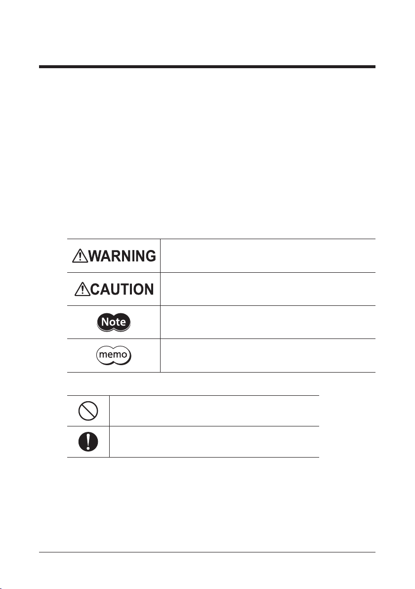
Description of signs
Handling the product without observing the instructions that
accompany a “WARNING” symbol may result in serious injury or
death.
Handling the product without observing the instructions
that accompany a “CAUTION” symbol may result in injury or
property damage.
The items under this heading contain important handling
instructions that the user should observe to ensure the safe
use of the product.
The items under this heading contain related information and
contents to gain a further understanding of the text in this
manual.
Description of graphic symbols
Indicates "prohibited" actions that must not be performed.
Indicates "compulsory" actions that must be performed.
Safety precautions
3
▌
Page 4
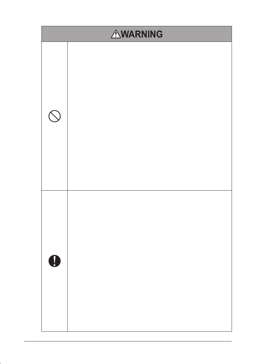
•Do not use the product in explosive or corrosive environments, in the
presence of ammable gases, locations subjected to splashing water, or near
combustibles. Doing so may result in re, electric shock or injury.
•Do not transport, install the product, perform connections or inspections
when the power is on. Doing so may result in electric shock.
•Do not forcibly bend, pull, or pinch the cable. Doing so may result in re or
electric shock.
•Do not disassemble or modify the product. Doing so may result in injury or
damage to equipment.
•Never use the product in a medical device used in connection with the
maintenance or management of human life or health, or in a transportation
system whose purpose is to move or carry people.
•Do not enter the moving range of the actuator while the power is supplied.
Be sure to provide a safety cage according to EN ISO13857. Also, when you
adjust or inspect while moving the ball screw part by hands, shut down the
driver main power supply. Doing so may cause serious injury.
•Do not use the brake mechanism of the electromagnetic brake motor for
braking the motor rotation or as a safety brake. Doing so may result in injury
or damage to equipment.
•Do not hit the joint of the actuator to the mechanical stopper other
than push-motion operation. Doing so may result in injury or damage to
equipment.
•Only qualied personnel should be allowed to perform installation,
connection, operation and inspection/troubleshooting of the product.
Handling by unqualied and uneducated personnel may result in re,
electric shock, injury or equipment damage.
•When setting the data, do so from outside the safety cage. Failure to do so
may result in injury.
•Take measures to keep the moving parts in position for vertical operations
such as elevator applications. Failure to do so will cause the moving parts to
fall and it may result in injury or damage to equipment.
•When the driver generates an alarm (=any of the driver’s protective functions
is triggered), the actuator will stop and lose its holding torque. Accordingly,
provide measures to hold the moving part in place in the event of an alarm.
Failure to do so may result in injury or equipment damage.
•Install the product in an enclosure. Failure to do so may result in electric
shock or injury.
•Operate the non-guide type actuator after setting the home position.
Operating the actuator without setting the home position may cause
unexpected movements, leading to injury or damage to equipment.
•Since this product is Class I Equipment, install it so that people cannot have
contact with it, or ground it if people may have contact with it. Failure to do
so may result in electric shock.
4
▌
Safety precautions
Page 5
•Provide an emergency stop device or emergency stop circuit externally so
that the entire equipment will operate safely in the event of a system failure
or malfunction. Failure to do so may result in injury.
•When the driver was replaced, set parameters such as the resolution, moving
direction and others before operating the actuator. Operating the actuator
without setting parameters may cause the ball screw to move to unexpected
directions or run at unexpected speeds, leading to injury or damage to
equipment.
•Do not use the product beyond the specications. Doing so may result in
electric shock, injury or damage to equipment.
•Keep your ngers and objects out of the openings in the product. Doing so
may result in re, electrical shock, or injury.
•Do not touch the product while operating or immediately after stopping.
Doing so may result in skin burn(s).
•Do not hold the moving part or cable. Doing so may result in injury.
•Keep the area around the product free of combustible materials. Doing so
may result in re or skin burn(s).
•Do not leave anything around the product that would obstruct ventilation.
Doing so may result in damage to equipment.
•Do not touch the moving part during operation. Doing so may result in
injury.
•Do not touch the terminals while conducting the insulation resistance
measurement or dielectric strength test. This may cause electric shock.
•While operating the actuator, do not make the cable contact with the
moving part. Disconnection of the cable may result in electric shock or
damage to equipment.
•Use an actuator and driver only in the specied combination. An incorrect
combination may cause a re.
•Dispose the product correctly in accordance with laws and regulations, or
instructions of local governments.
•Wear a helmet, safety shoes, gloves or other protective gears when
transporting or installing the product. Failure to do so may result in injury.
•Since the motor surface temperature may exceed 70 °C
(158 °F) even under normal operating conditions, ax
the warning label as shown in the gure in a conspicuous
position. Failure to do so may result in skin burn(s).
Warning label
Safety precautions
5
▌
Page 6

3 Preparation
GuideGuide
3-1 Checking the product
Verify that the items listed below are included. Report any missing or damaged items to the
branch or sales oce from which you purchased the product.
•Compact motorized cylinder ............1 unit
•OPERATING MANUAL Actuator.........1 copy (this document)
3-2 How to identify the actuator model
Verify the model number of the purchased product against the model number shown on the
nameplate.
DRSM 42 R G - 04 A 2 AZ M K
1 2 3 4 5 6 7 8 9 10
1 Series name
2 Frame size
3 Cable direction *
4 Type
5 Stroke
6 Ball-screw shaft type
7 Ball screw lead
8 Equipped motor
9 Electromagnetic brake
10 Motor power supply typeK: DC power input
* The cable direction can be specied in the guide type actuator. It represents the cable
direction viewed from the encoder (ABZO sensor) side with the guide up.
Encoder
(ABZO sensor)
Cable direction: Right Cable direction: Left
DRSM: DRS2
: 42 mm (1.65 in.) 60: 60 mm (2.36 in.)
42
: Right direction L: Left direction
R
Blank: Without a guide
: Guide type Blank: Non-guide type
G
: 40 mm 05: 50 mm
04
: Rolled ball screw B: Ground ball screw
A
: 2 mm 4: 4 mm 8: 8 mm
2
AZ: AZ
: Without electromagnetic brake
A
: With electromagnetic brake
M
Cable
Series
Series
Encoder
(ABZO sensor)
6
▌
Preparation
Page 7
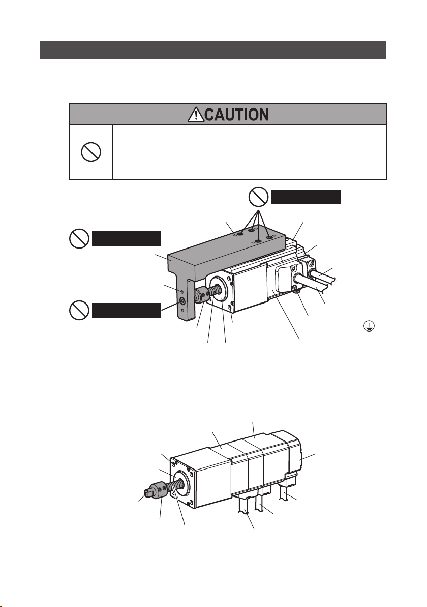
3-3 Names of parts
Electromagnetic brake
The moving part of the actuator is shown in gray color.
Guide type
Do not remove the joint from the ball screw shaft. Doing so may deteriorate
the installation accuracy of the ball screw shaft, resulting in malfunction. In
addition, if the joint is removed, the home position which has been set in the
encoder (ABZO sensor) at the time of shipment may deviate. This may cause
unexpected movements of the actuator, leading to damage to equipment.
Load mounting holes in the
linear guide side (4 places)
Do not remove
Joint
Load mounting holes in
the ball screw shaft side
(2 places)
Do not loosen
Set collar *
Ball screw shaft Pilot
* It prevents the screw shaft from retracting completely into the case.
Non-guide type
The illustration shows an electromagnetic brake type.
Mounting holes
(4 places)
Pilot
Motor
Do not loosen
Mounting holes
(4 places)
Linear guide
Encoder
(ABZO sensor)
Encoder cable
Motor cable
Protective Earth
Terminal
Motor
Encoder
(ABZO sensor)
Load mounting hole
Set collar *
Encoder cable
Electromagnetic brake cabale
Ball screw shaft
* It prevents the screw shaft from retracting completely into the case.
Preparation
Motor cable
7
▌
Page 8
4 Precautions for use
This section covers limitations and requirements the user should consider when using the
product.
zGeneral
•Always use an accessory cable to connect the actuator and driver.
•Be sure to provide an anti-spin mechanism for the non-guide type actuator. The actuator
cannot be operated without the anti-spin mechanism because the ball screw rotates idly.
•Do not remove the set collar attached to the ball screw shaft. Doing so may result in
damage to ball screw shaft.
•Do not remove the joint of the guide type actuator from the ball screw shaft. Doing so
may deteriorate the installation accuracy of the ball screw shaft, resulting in malfunction
or shorter service life of the actuator. In addition, if the joint is removed, the home position
which has been set in the encoder (ABZO sensor) at the time of shipment may deviate. This
may cause unexpected movements of the actuator, leading to damage to equipment.
•When conducting the insulation resistance measurement and the dielectric strength test,
be sure to separate the connection between the actuator and the driver. Conducting the
insulation resistance measurement or dielectric strength test with the actuator and driver
connected may result in damage to the product.
•Do not drop the actuator, and do not hit the motor and mechanism sections against other
objects. Doing so may cause the positioning accuracy decrease, the motor section damage
or the product service life reduction.
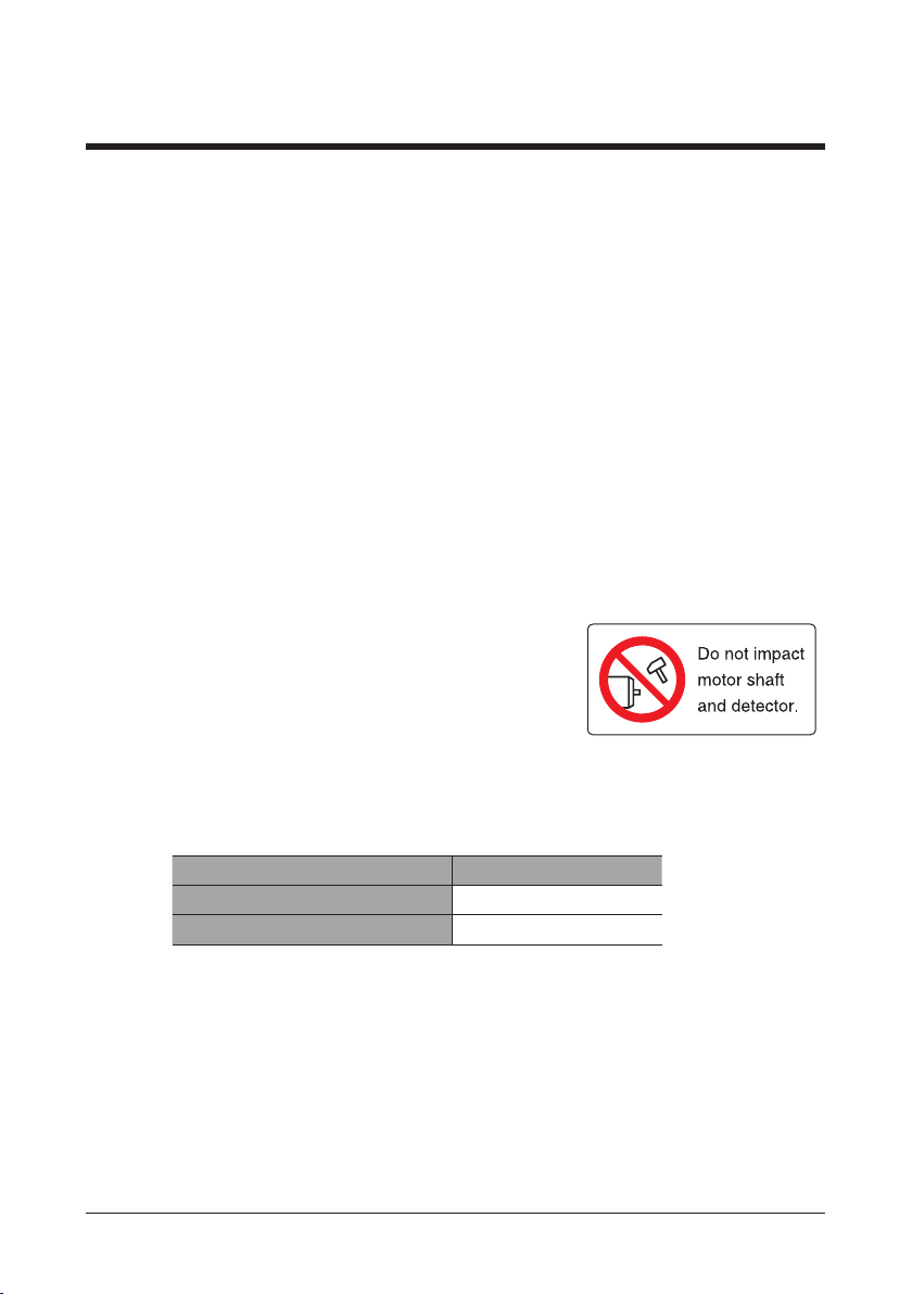
•Do not make a strong impact on the encoder (ABZO
sensor). Making a strong impact on an encoder (ABZO
sensor) may cause the actuator malfunction or damage
to the encoder (ABZO sensor). The warning label shown
in the right is attached on the motor.
•Do not move the encoder (ABZO sensor) toward a strong magnetic eld. A magnetic
sensor is built into the encoder (ABZO sensor). If the actuator is installed close to
equipment which generates a strong magnetic eld, the encoder (ABZO sensor) may
break or malfunction. Keep the magnetic ux density on the surface of the encoder (ABZO
sensor) so as not to exceed the values in the table.
Magnetic ux density
When operating 10 mT
When transporting and storing 10 mT
•A gear type mechanical sensor is built into the encoder (ABZO sensor). Although the
meshing noise of gears may generate, it is not malfunction.
•When you install a carrier guide for load transportation, use the non-guide type actuator.
Using the guide type actuator may cause unconformity between guides, leading to
damage to equipment.
•When transporting the actuator or installing a load, handle it carefully not to make a
strong impact on the moving part.
8
▌
Precautions for use
Page 9

zTemperature
•In order to protect the encoder (ABZO sensor), use the actuator so that the surface
temperature on the motor case does not exceed 80 °C (176 °F). If the surface temperature
on the motor case may exceed 80 °C (176 °F), improve the operating conditions such
as ambient temperature, operating speed, duty cycle and others. If the encoder (ABZO
sensor) temperature reaches the upper limit, the motor overheat protection alarm will
generate.
zOperation
•Operate an actuator in the range of the operating ambient temperature. If the actuator is
operated outside the operating ambient temperature, the viscosity of grease may change,
causing the thrust force to decrease.
•Keep 20 m (65.6 ft.) or less for the wiring distance between the actuator and driver.
Exceeding 20 m (65.6 ft.) may cause the thrust force to decrease.
•The holding torque is decreased by the current cutback function of the driver when the
actuator stops. When selecting the actuator, make sure the holding torque at standstill by
checking the catalog specication.
•Do not use the electromagnetic brake as a safety brake. To use the electromagnetic brake
to hold the load in position, do so after the actuator operation is stopped.
•Do not use the electromagnetic brake as a means to decelerate and stop the actuator.
The brake hub of the electromagnetic brake will wear signicantly and the braking force
will drop. Since the power o activated type electromagnetic brake is equipped, it helps
maintain the position of the load when the power is cut o, but this brake cannot securely
hold the load in place.
•Do not press the ball screw shaft against a load at the speed exceeding the maximum
push speed or the maximum push-motion return-to-home speed. The mechanical impact
may cause damage to the actuator. If the ball screw shaft was pressed at high speed, take
measures by referring to "10 Troubleshooting and remedial action" on p.31.
zInspection
•Grease on the ball screw shaft may darken within a short time after the start of operation.
Refer to "8 Maintenance" on p.27, and wipe o the dirty grease to apply new grease.
•If an abnormal noise (i.e., from deection or interference) is generated while operating the
non-guide type actuator, the installation accuracy may have dropped. Stop the operation
and check the installation accuracy of the ball screw shaft.
Precautions for use
9
▌
Page 10

5 Installing the guide type
This section explains the installation location, installation method and load mounting method
of the guide type actuator.
5-1 Installation location
The actuator has been designed and manufactured to be incorporated in general industrial
equipment. Install the product in a well-ventilated location that provides easy access for
inspection.
•Inside an enclosure that is installed indoors (provide vent holes)
•Operating ambient temperature: 0 to +40 °C [+32 to 104 °F] (non-freezing)
•Operating ambient humidity: 85% or less (non-condensing)
•Area that is free of explosive atmosphere or toxic gas (such as sulfuric gas) or liquid
•Area not exposed to direct sun
•Area free of excessive amount of dust, iron particles or the like
•Area not subject to splashing water (rain, water droplets), oil (oil droplets) or other liquids
•Area free of excessive salt
•Area not subject to continuous vibration or excessive shocks
•Area free of excessive electromagnetic noise (from welders, power machinery, etc.)
•Area free of radioactive materials, magnetic elds or vacuum
•Up to 1000 m (3300 ft.) above sea level
If a motor is installed in an environment where a magnetic eld is
generated
A magnetic sensor is built into the encoder (ABZO sensor). If the motor is installed close to
equipment which generates a strong magnetic eld, the encoder (ABZO sensor) may break
or malfunction. Make sure to prevent the magnetic ux density on the surface of the encoder
(ABZO sensor) from exceeding 10 mT.
Do not install the motor close to equipment which generates a strong magnetic
eld.
5-2 Installation method
The actuator can be installed in any direction.
Install the actuator onto an appropriate metal at mounting plate [thickness approximately
5 mm (0.2 in.) or more] having excellent vibration resistance and heat conductivity. If a
high accuracy is required, design the thickness of the mounting plate in consideration of
installation conditions such as load condition, rigidity, vibration, and others.
An accessory mounting plate is provided. Refer to p.12 for the installation method using the
accessory mounting plate.
10
▌
Installing the guide type
Page 11

Details of actuator mounting hole
8
ø4.5
2
31±0.1
31±0.1
•Screw size: M4
•Tightening torque: 1.8 N·m (250 oz-in)
Unit: mm
Component part design
The following shows the recommended design dimension of component part required for
when the actuator is installed.
zMounting plate
Perform machining for a through hole of
the ange pilot and a clearance groove of
the set collar on the mounting plate.
(1.22±0.004)
(1.22±0.004)
16 (0.63)
Unit: mm (in.)
+0.021
25 [H7]
0
+0.0008
(0.98 )
0
4×ø4.5 (ø0.18)
Installation example
Do not remove
Joint
Do not loosen
Clearance groove
(through hole)
Pilot
Do not remove the joint from the ball screw shaft. Doing so may deteriorate
the installation accuracy of the ball screw shaft, resulting in malfunction. In
addition, if the joint is removed, the home position which has been set in the
encoder (ABZO sensor) at the time of shipment may deviate. This may cause
unexpected movements of the actuator, leading to damage to equipment.
Installing the guide type
Pilot
Set collar
Mounting plate
Base plate
Do not loosen
Screws
11
▌
Page 12

5-3 Installation using an accessory mounting plate
The accessory mounting plate is a dedicated bracket (steel) to install the actuator onto a base
plate. Screws to secure the actuator to the mounting plate are provided (M4, 4 pieces).
Securing the actuator
Secure the actuator to the mounting plate using the supplied screws (M4, 4 pieces).
Mounting holes
Screws provided with product (M4, 4 pcs.)
Tightening torque: 1.8 N·m (250 oz-in)
Mounting plate (accessory)
Mounting methods of the mounting plate (accessory)
There are three methods to secure the mounting plate.
Secure the mounting plate to the base plate using two screws (not supplied).
zMounting method A zMounting method B zMounting method C
•Screw size: M5
•Eective depth of screw
thread: 10 mm
•Tightening torque:
5.0 N·m (710 oz-in)
•Screw size: M6
•Eective depth of screw
thread: 7.5 mm
•Tightening torque:
5.0 N·m (710 oz-in)
•Screw size: M5
•Tightening torque:
5.0 N·m (710 oz-in)
Base plate
Base plate
12
▌
Installing the guide type
Base plate
Page 13

5-4 How to install a load
tive depth
Install a load to the load mounting holes in the joint using screws (not supplied). There are
two load mounting surfaces, which are provided on the linear guide side and the ball-screw
shaft side.
When using load mounting holes in the linear guide side of the
joint
•Screw size: M4
•Eective depth of screw thread: 5.5 mm (0.22 in.)
•Tightening torque: 1.0 N·m (142 oz-in)
Load
Screws
Beware of the length
Load mounting holes
Do not loosen
Do not remove
Joint
Do not loosen
Use the screws which length does not exceed the eective depth of screw
threads in the joint when securing a load. Using a too long screw may cause
the screw to oat, leading to break. This may result in injury or damage to
equipment.
Screw is oated
Joint
Linear guide
Load
Eec
of screw thread
Do not remove the joint from the ball screw shaft. Doing so may deteriorate
the installation accuracy of the ball screw shaft, resulting in malfunction. In
addition, if the joint is removed, the home position which has been set in the
encoder (ABZO sensor) at the time of shipment may deviate. This may cause
unexpected movements of the actuator, leading to damage to equipment.
Installing the guide type
13
▌
Page 14

When using load mounting holes in the ball screw shaft side of
Screws
the joint
1. Retract the ball screw shaft until it stops at the set collar.
2. Secure the load with screws.
•Screw size: M4
•Eective depth of screw thread: 7.5 mm
•Tightening torque: 1.0 N·m (142 oz-in)
Load mounting holes
Load
Do not loosen
Do not remove
Joint
Do not remove the joint from the ball screw shaft. Doing so may deteriorate
the installation accuracy of the ball screw shaft, resulting in malfunction. In
addition, if the joint is removed, the home position which has been set in the
encoder (ABZO sensor) at the time of shipment may deviate. This may cause
unexpected movements of the actuator, leading to damage to equipment.
Set collar
Notes for when installing a load
•Although the guide type actuator can receive a load moment, use it less than the
specications. Operating the actuator under an excessive load moment may cause
malfunction or shorter service life of the actuator. Check on the Oriental Motor Website for
the product specications.
•If you want to move the position of the ball screw shaft when installing a load to an
electromagnetic brake type actuator, refer to p.26 to release the electromagnetic brake.
14
▌
Installing the guide type
Page 15

6 Installing the non-guide type
This section explains the installation location and installation method of the non-guide type
actuator.
6-1 Installation location
The actuator has been designed and manufactured to be incorporated in general industrial
equipment. Install the product in a well-ventilated location that provides easy access for
inspection.
•Inside an enclosure that is installed indoors (provide vent holes)
•Operating ambient temperature: 0 to +40 °C [+32 to 104 °F] (non-freezing)
•Operating ambient humidity: 85% or less (non-condensing)
•Area that is free of explosive atmosphere or toxic gas (such as sulfuric gas) or liquid
•Area not exposed to direct sun
•Area free of excessive amount of dust, iron particles or the like
•Area not subject to splashing water (rain, water droplets), oil (oil droplets) or other liquids
•Area free of excessive salt
•Area not subject to continuous vibration or excessive shocks
•Area free of excessive electromagnetic noise (from welders, power machinery, etc.)
•Area free of radioactive materials, magnetic elds or vacuum
•Up to 1000 m (3300 ft.) above sea level
If a motor is installed in an environment where a magnetic eld is
generated
A magnetic sensor is built into the encoder (ABZO sensor). If the motor is installed close to
equipment which generates a strong magnetic eld, the encoder (ABZO sensor) may break
or malfunction. Make sure to prevent the magnetic ux density on the surface of the encoder
(ABZO sensor) from exceeding 10 mT.
Do not install the motor close to equipment which generates a strong magnetic
eld.
Installing the non-guide type
15
▌
Page 16

6-2 Installation overview
Centering adjustment plate *
[X+Y]±0.1 (0.0039)
The non-guide type actuator cannot be operated without an anti-spin mechanism for the ball
screw shaft because the shaft rotates idly. Be sure to provide an anti-spin mechanism such as
a guide rail or a movable plate.
Mounting plate
Movable plate
Anti-spin
mechanism
With the non-guide type actuator, the customer is required to perform centering between the
actuator and anti-spin mechanism. The installation method varies depending on whether the
component parts of anti-spin mechanism have an accuracy that centering can be performed.
If the component parts does not have enough accuracy to perform centering, jigs (centering
shaft, centering adjustment plate) are needed.
Guide block
Guide rail
Base plate
Movable plate
16
▌
Y
X
Base plate
Guide rail Guide block
* It is used when the accuracy of component parts is not enough to perform centering. Also, it
is used when the stacking tolerance of parts is adjusted.
•Be sure to check the installation accuracy using a feeler gauge and others. Low
installation accuracy may result in malfunction or shorter service life of the
actuator.
•When the electromagnetic brake type actuator is used, refer to p.26 to release
the electromagnetic brake before installation. The ball screw shaft cannot be
moved unless the electromagnetic brake is released.
Installing the non-guide type
Mounting plate Unit: mm (in.)
[X+Y]±0.05 (0.0020)
Page 17

Process of installation
8
ø4.5
2
10
ø5.5
4
Install the non-guide type actuator according to the following process.
Designing the parts (_p.18)
Installing the actuator (
Step1 Installing the positioning pin (_p.20)
_
p.20)
Step2 Installing the guide rail (_p.20)
Step3 Installing the mounting plate (_p.21)
Step4 Installing the movable plate (_p.21)
Step5 Installing the actuator (_p.24)
Details of actuator mounting hole
DRSM42
z
•Screw size: M4
•Tightening torque:
1.8 N·m (250 oz-in)
DRSM60
z
•Screw size: M5
•Tightening torque:
5.0 N·m (710 oz-in)
Unit: mm
Installing the non-guide type
17
▌
Page 18

6-3 Installation method
The actuator can be installed in any direction.
Install the actuator onto an appropriate metal at mounting plate [thickness approximately
5 mm (0.2 in.) or more] having excellent vibration resistance and heat conductivity. If a
high accuracy is required, design the thickness of the mounting plate in consideration of
installation conditions such as load condition, rigidity, vibration, and others.
A mounting plate is provided as an accessory.
Component parts design
The following shows the recommended design dimension of component parts and jigs
required for when the actuator is installed.
zMovable plate
Design a screw shaft mounting hole (øC) of the movable plate in consideration of a margin so
that the stacking tolerances of parts can be adjusted.
øR * øC øR *
B
* They are needed when the accuracy of component parts is not enough to perform
centering.
Model
DRSM42
DRSM60
When centering is possible When centering is dicult
øC øC øR
4.5 (0.177) 5 (0.20) 4 (0.16)
9 (0.354) 9 (0.35) 6 (0.24)
A0.02 (0.0008) B0.01 (0.0004)
A
Unit: mm (in.)
18
▌
Installing the non-guide type
Page 19

zMounting plate
Flange pilot section
+ 0.021
+ 0.0008
+ 0.025
+ 0.0010
-
0.007
-
0.0003
-
0.004
-
0.0002
+ 0.012
+ 0.0005
Perform machining of a ange pilot (counterbore or through hole) on the mounting plate.
Design the ange pilot according to the centering shaft (jig) if the accuracy of component
parts is not enough to perform centering.
The gure shows an example for a through hole.
A0.02 (0.0008) B0.01 (0.0004)
A
S
B
Model øD øN S
DRSM42
DRSM60
(0.98
36
(1.42
[H7]
0
0
[H7]
0
0
4.5 (0.177)
)
5.5 (0.22)
)
31±0.1
(1.22±0.004)
50±0.1
(1.97±0.004)
25
A mounting plate is provided as an accessory. The accessory mounting plate is a
dedicated bracket (steel) to install the actuator onto a base plate.
Screws (4 pieces) to secure the actuator to the mounting plate are provided.
zCentering shaft and centering adjustment plate
The centering shaft and the centering adjustment plate are jigs used for when the accuracy
of component parts is not enough to perform centering. Also, it is used when the stacking
tolerance of parts is adjusted.
Centering shaft
Centering adjustment plate
S
4×øN
øD
Unit: mm (in.)
I
F
J
K I
K J
P
P-P’
øL
øG
øE
P’
N
H
Model øE F øG H K øL
DRSM42
DRSM60
(0.98
36
(1.42
-
-
-
0.020
-
0.009
0.025
-
-
[g6]
0.0008
[g6]
0.0004
0.0010
2
(0.079)
)
2
(0.079)
)
4
-
0.012
(0.157
8
(0.315
)
-
0.0005
-
0.005
-
0.014
-
0.0002
)
-
0.0006
20
(0.79)
24.5
(0.96)
0.02
(0.0008)
0.02
(0.0008)
4
(0.157
8
(0.315
25
Unit: mm (in.)
Installing the non-guide type
0
+ 0.015
0
[H7]
0
(H7)
+ 0.0006
0
19
N0.02 (0.0008)
)
)
▌
Page 20

Installation procedure
Positioning pin for
The installation procedure varies based on the accuracy of component parts of equipment.
•If the accuracy of component parts enables centering without adjustment: Centering does
not required.
•If the accuracy of component parts is not enough to perform centering: Perform centering
using jigs.
Step1 Installing the positioning pin
Install positioning pins (each 2 pcs.), which are used to set the position of the guide rail and
mounting plate, on the base plate.
mounting plate
Positioning
pins
Intersect at
a right angle
Base plate
Intersect at a
right angle
Step2 Installing the guide rail
Secure a guide rail to the base plate using screws while pressing the reference surface of the
guide rail to the positioning pin.
Check the manufacturer of a guide rail for the position of the reference surface of the guide
rail.
Press
Reference surface
of the guide rail
Positioning pin
for guide rail
Positioning pin
for guide rail
Positioning pin
for guide rail
20
▌
Installing the non-guide type
Page 21

Step3 Installing the mounting plate
Place the mounting plate on the pins, and secure the mounting plate to the base plate with
screws.
Positioning pin for mounting plate
Step4 Installing the movable plate
Install the movable plate to the guide block. The installation method varies depending on the
accuracy of component parts.
zIf the accuracy of component parts enables centering without adjustment
1. Install positioning pins on the movable plate.
Ball screw shaft mounting hole
Positioning pin for movable plate
2. Secure the movable plate to the guide block using screws while pressing the positioning
pins on the movable plate to the reference surface of the guide block.
Check the manufacturer of a guide rail for the position of the reference surface of the
guide block.
Press
Positioning pin
Reference surface
of guide block
Guide block
Installing the non-guide type
21
▌
Page 22

zIf the accuracy of component parts is not enough to perform centering
1. Secure the centering adjustment plate to the movable plate using screws.
Movable plate
Centering adjustment plate
2. Secure the movable plate to the guide block using screws.
Guide block
3. Move the movable plate closer to the mounting plate, and check that there is no gap
between the plates.
When there is a distance between the movable plate and the mounting plate, put a block
gauge, and check that there is no gap between the plates.
If there is a gap, reinstall the movable plate.
Block gauge
22
▌
No gap
Installing the non-guide type
No gapNo gap
Page 23

Centering shaft
4. Using the centering shaft to resemble the actuator, insert the centering shaft to the
mounting plate.
Loosen the screws securing the centering adjustment plate, and temporarily x the
screws so as to move slightly when touching the centering adjustment plate.
Centering adjustment plate
Mounting plate
Fix screws temporarily
5. Slide the movable plate to check that it moves smoothly, and tighten the screws on the
centering adjustment plate.
If the movable plate does not move smoothly, adjust axis misalignment between
the centering shaft and the centering adjustment plate while moving the centering
adjustment plate from right to left or up and down.
Model Screw size Tightening torque *
DRSM42
DRSM60
* The tightening torques shown in the table are reference values. Tighten the suitable force
according to the material and thickness of the centering adjustment plate.
6. Remove the centering shaft.
M3 0.6 N·m (85 oz-in)
M5 3 N·m (420 oz-in)
Installing the non-guide type
23
▌
Page 24

Step5 Installing the actuator
1. Secure the actuator to the mount plate using screws.
Secure with the provided screws (4 pieces) when using the accessory mounting plate.
Model Screw size Tightening torque
DRSM42
DRSM60
2. Insert the ball screw shaft of the actuator into the ball screw shaft mounting hole of the
movable plate, and secure the tip with a screw.
Ball screw shaft mounting hole
M4 1.8 N·m (256 oz-in)
M5 5 N·m (710 oz-in)
24
▌
Model Screw size Tightening torque Eective depth of screw threads
DRSM42
DRSM60
3. Perform test operation to check that no abnormal noise is generated.
M4 1.8 N·m (256 oz-in) 10 mm
M8 5 N·m (710 oz-in) 15 mm
Installing the non-guide type
Page 25

7 Connection
This chapter explains the grounding method of the actuator as well as the method to release
an electromagnetic brake.
7-1 Grounding the actuator
Since a grounding wire is included in the "cable for motor," you can ground it only to connect
with a driver. However, the grounding resistance value provided in the standards in which the
user applies to the equipment may not be satised depending on the type or length of the
"cable for motor." In this case, also ground the actuator Protective Earth Terminal.
Input voltage
24 VDC Required Not required
48 VDC Required
When multiple actuators are used in combination, connect each one to the
grounding point.
Driver Protective Earth Terminal of actuator
Ground if the grounding resistance of the standards that
applies to the equipment is not satised.
When connecting to the driver to ground the actuator:
1. Connect the "cable for motor" to the motor connector on the driver.
2. Ground the driver Protective Earth Terminal.
Be sure to ground the Protective Earth Terminal of the driver. Refer to the AZ Series
OPERATING MANUAL Driver for how to ground the driver.
Grounding method
Cable for motor
Connect the “cable for motor”
to the motor connector on the
driver.
Connection
Grounding
25
▌
Page 26

When grounding the actuator Protective Earth Terminal
DC power
(48 VDC only):
Be sure to ground the Protective Earth Terminal of
the actuator.
•Grounding wire: AWG18 (0.75 mm2) or more
•Screw size: M4
•Tightening torque: 1.2 N·m (170 oz-in)
To ground the actuator, use a round terminal, bolt and washer.
Do not share a grounding wire with a welder or any other power equipment.
A grounding wire and crimp terminal are not supplied.
7-2 Releasing the electromagnetic brake
Perform according to the following steps to release an electromagnetic brake.
1. Connect the "electromagnetic brake cable" and "cable for electromagnetic brake."
2. Connect the lead wires of the “cable for electromagnetic brake” to the 24 VDC power
supply.
Connect the white lead wire to the +24 VDC terminal, and the black lead wire to the GND
terminal.
When the power is turned on, the electromagnetic brake is released and the moving part
of the actuator can be moved by hand.
Cable for
Electromagnetic
brake cable
electromagnetic
brake
White
Black
Varistor *3
Switch
Grounding
supply *1 *2
24 VDC±5%
*1 If the distance between the electromagnetic brake type actuator and the driver is
extended to 20 m (65.6 ft.) using an accessory cable, use the power supply of 24 VDC±4%.
*2 Refer to the following current capacities for the 24 VDC power supply.
DRSM42
DRSM60
*3 Connect the varistor to protect the contact of the switch or to prevent electrical noise.
[Recommended varistor: Z15D121 (SEMITEC Corporation)]
26
▌
: 0.08 A or more
: 0.25 A or more
The lead wires of the "cable for electromagnetic brake" have polarities, so
connect them in the correct polarities. If the lead wires are connected with their
polarities reversed, the electromagnetic brake will not operate properly.
Connection
Page 27

8 Maintenance
This chapter explains maintenance items to operate an actuator safely and eciently. If an
abnormal condition is noted, discontinue any use and contact your nearest Oriental Motor
sales oce.
8-1 Inspection item and timing
If the actuator is operated eight hours a day, perform maintenance according to the applicable
period specied in the table. Reduce maintenance intervals accordingly if the operating rate is
high such as continuous operation for twenty-four hours.
Maintenance timing
When operated for the rst time
A week after initial operation
Every a month thereafter
External
inspection
External inspection
Check the items specied in table.
Item Description Remedial action
•Are there any loose screws which have
Actuator
Cable,
connector
Operation
mounted the actuator?
•Are there any loose screws which have
mounted the load?
•Are there any scratches or areas under
stress on the cable?
•Are there any loose connections on
the actuator or driver?
Is there any abnormal noise or vibration
from the bearings, etc.?
External
cleaning
Tighten the screws securely.
•Replace the cable.
•Disconnect and reconnect
the connector.
Check the installation of the
load and operation speed.
Internal
inspection
−
External cleaning
Clean the exterior surface of the actuator whenever necessary.
•Wipe o any dirt and stains using a soft cloth.
•Do not apply compressed air. Dust may enter from a space, resulting in malfunction.
•To remove stubborn stains, wipe the area using a soft cloth moistened with neutral
detergent.
•Do not use petroleum solvents, since they will damage the coated surface.
Maintenance
27
▌
Page 28

Internal inspection
Non-guide type
Guide type
Visually check the items specied in table. Even if the grease has turned brown, lubrication
condition is deemed appropriate if the running surface still appears glossy. Refer to "8-2
Grease lubrication" for how to apply grease.
Item Description Remedial action
Ball screw
shaft
Linear
guide
Are there any deposits of foreign
matter such as dust?
Has the grease lost its gloss or been
consumed?
Are there any deposits of foreign
matter such as dust?
Has the grease lost its gloss or been
consumed?
Remove the foreign matter.
Clean the ball screw shaft with a soft
cloth and apply grease to the nut
running groove.
Remove the foreign matter.
Use a soft cloth to clean the ball rolling
grooves on both sides of the linear
guide, and add grease from the grease
nipple.
8-2 Grease lubrication
Wear protective goggles when applying grease. Pay attention to safety and
handle the grease carefully by following the instructions provided with
that product. If grease gets into the eyes or comes in contact with the skin,
immediately ush the area thoroughly with water.
Wipe o the old grease and any dirt completely with a soft cloth, and apply new grease.
Grease to be used : AFC grease (THK Co., LTD.)
▌
28
Ball screw shaft
Linear guide
(Apply grease to the
opposite side as well)
Maintenance
Ball screw shaft
Page 29

9 Standards and general specications
9-1 Standards
EU Directives
zInstallation conditions
Overvoltage category II
Protection against electric shock Class I equipment
Pollution degree 3
Noise level 70 dB or less (guide type only)
zEMC Directive
The driver combining with the actuator is axed the CE Marking under the EMC Directive. For
details about applicable standards and others, check with the "OPERATING MANUAL Driver" of
the AZ Series.
zMachinery Directive (guide type only)
The actuators and drivers have been designed and manufactured to be incorporated in
general industrial equipment, and a Declaration of Incorporation of Partly Completed
Machinery is issued with them according to the Machinery Directive.
Applicable standard: EN ISO 12100
RoHS Directive
The products do not contain the substances exceeding the restriction values of RoHS Directive
(2011/65/EU).
9-2 General specications
Operating environment
Degree of
protection
Ambient
temperature
Ambient
humidity
Altitude
0 to +40 °C [+32 to +104 °F]
Up to 1000 m (3300 ft.) above
Standards and general specications
− −
(non-freezing)
sea level
Storage
environment
–20 to +60 °C [–4 to +140 °F]
(non-freezing)
85% or less (non-condensing)
Up to 3000 m (10,000 ft.)
above sea level
Shipping
environment
29
▌
Page 30

9-3 Power supply capacity
Model
DRSM42
DRSM60
* If the distance between the electromagnetic brake type actuator and the driver is extended
to 20 m (65.6 ft.) using an accessory cable, use the power supply of 24 VDC±4%.
Electromagnetic
brake
Not equipped
Equipped 1.80 A or more
Not equipped 2.45 A or more
Equipped 2.7 A or more
Input power supply
voltage
24 VDC±5% *
48 VDC±5%
Current capacity
1.72 A or more
30
▌
Standards and general specications
Page 31

10 Troubleshooting and remedial action
During actuator operation, the actuator may fail to function properly due to an improper
setting or wiring. When the actuator cannot be operated properly, refer to the contents
provided in this section and take an appropriate action. If the problem persists, contact your
nearest Oriental Motor sales oce.
Phenomenon Possible cause Remedial action
While push-motion
operation is executed, the
ball screw shaft does not
move with being jammed
in the nut part.
The ball screw shaft does
not move with being
jammed.
The ball screw shaft
does not operate at the
command speed.
The ball screw shaft rotates
idly. (for non-guide type
actuator)
Malfunction of actuator
The thrust force of the
actuator has lowered.
The ball screw shaft was
stopped by hitting against
a load or others at a speed
exceeding the maximum push
speed (6 mm/s).
The operation was executed
under conditions where
the speed or the load was
exceeded the specication
value.
The torque of the actuator is
not enough against a load.
An anti-spin mechanism is not
provided.
•The installation accuracy is
low.
•A load moment exceeding
the specication value is
applied.
•The wiring distance is
exceeded the specication
value.
•The viscosity of the grease
was changed.
Return the ball screw shaft at the
recommended speed shown in the
table below, and check if the ball
screw shaft and the load are not
damaged.
Return the ball screw shaft at the
recommended speed shown in the
table below. After that, check the
following items.
•Are the ball screw shaft and the
load damaged?
•Are the positions of the set collar
and the home position displaced?
Review the load.
Be sure to provide an anti-spin
mechanism for the non-guide type
actuator.
•Check the installation accuracy.
•Use the actuator with a load
moment of the specication value
or smaller.
•Keep 20 m (65.6 ft.) or less for
the wiring length between the
actuator and driver.
•Refer to p.29, and check the
operating ambient temperature.
Recommended starting speed
Model Lead Recommended starting speed
DRSM42
DRSM60
2 mm 0.4 mm/s
8 mm 1.6 mm/s
4 mm 0.8 mm/s
31
▌
Page 32

• Please contact your nearest Oriental Motor oce for further information.
•Unauthorized reproduction or copying of all or part of this Operating Manual is prohibited.
If a new copy is required to replace an original manual that has been damaged or lost, please
contact your nearest Oriental Motor branch or sales oce.
•Oriental Motor shall not be liable whatsoever for any problems relating to industrial property rights
arising from use of any information, circuit, equipment or device provided or referenced in this
manual.
•Characteristics, specications and dimensions are subject to change without notice.
•While we make every eort to oer accurate information in the manual, we welcome your input.
Should you nd unclear descriptions, errors or omissions, please contact the nearest oce.
•
and ABZO sensor are registered trademarks or trademarks of Oriental Motor Co.,
Ltd., in Japan and other countries.
Other product names and company names mentioned in this manual may be registered trademarks
or trademarks of their respective companies and are hereby acknowledged. The third-party
products mentioned in this manual are recommended products, and references to their names shall
not be construed as any form of performance guarantee. Oriental Motor is not liable whatsoever for
the performance of these third-party products.
© Copyright ORIENTAL MOTOR CO., LTD. 2015
Published in June 2018
Technical Support Tel:(800)468-3982
8:30 A.M. to 5:00 P.M., P.S.T. (M-F)
7:30 A.M. to 5:00 P.M., C.S.T. (M-F)
www.orientalmotor.com
Tel:+55-11-3266-6018
www.orientalmotor.com.br
Schiessstraße 44, 40549 Düsseldorf, Germany
Technical Support Tel:00 800/22 55 66 22
www.orientalmotor.de
Tel:01256-347090
www.oriental-motor.co.uk
Tel:01 47 86 97 50
www.orientalmotor.fr
Tel:02-93906346
www.orientalmotor.it
Singapore
Tel:1800-8420280
www.orientalmotor.com.sg
Tel:1800-806161
www.orientalmotor.com.my
Tel:1800-888-881
www.orientalmotor.co.th
Tel:+91-80-41125586
www.orientalmotor.co.in
Tel:0800-060708
www.orientalmotor.com.tw
Tel:400-820-6516
www.orientalmotor.com.cn
Korea
Tel:080-777-2042
www.inaom.co.kr
Hong Kong Branch
Tel:+852-2427-9800
4-8-1 Higashiueno, Taito -ku, Tokyo
110-8536 Japan
Tel:03-6744-0361
www.orientalmotor.co.jp
 Loading...