

Page 1

Controller Module
CM10 Series
OPERATING MANUAL
Thank you for purchasing an Oriental Motor product.
This Operating Manual describes product handling procedures and safety precautions.
• Please read it thoroughly to ensure safe operation.
• Always keep the manual where it is readily available.
This Operating Manual supports the firmware version 2.1x.
HP-13014-7
Page 2

Table of Contents
- 2 -
1 Before Use ........................................... 3
1.1 Main Features ................................................ 3
1.2 About Function Improvements..........................4
1.3 System Configuration .......................................6
1.4 Operating Methods ........................................... 7
1.5 Immediate Motion Creator
for CM/SCX Series.... 8
1.6 Standards and CE Marking............................... 8
2 Safety Precautions ...........................................9
3 Precautions for Use ......................................... 11
4 Preparation ......................................... 12
4.1 Checking the Product ..................................... 12
4.2 How to Identify the Product Model .................. 12
4.3 Combinations of CM10 and Drivers ............... 13
4.4 Names and Functions of Parts........................ 14
5 Installation ......................................... 15
5.1 How to Install CM10 on the Driver.................. 15
5.2 Installing the Driver ......................................... 18
5.3 Installing and Wiring in Compliance
with EMC Directive... 18
6 Connection ......................................... 20
6.1 Overview .............................................. 20
6.2 Connecting the Power Supply ........................ 21
6.3 Connecting the USB and Installation
of Utility Software ..... 22
6.4 Connecting the I/O Signals ............................. 25
6.4.1 Pin Assignments...........................................25
6.4.2 Input Signals .............................................. 27
6.4.3 Output Signals .............................................. 30
6.4.4 Connection Example of I/O........................... 33
6.5 Driver I/O Setting (CM10-1 and CM10-3) ..... 35
6.6 Connecting the RS-232C................................ 37
6.7 Connecting the CANopen ............................... 39
6.8 Connecting the External Encoder ................... 40
7 Start Up (Immediate Command).......................... 42
7.1 Overview .............................................. 42
7.2 Preparation .............................................. 42
7.3 Setting the User Unit....................................... 43
7.4 Making the Motor Move
(Immediate Command).... 46
7.5 Command Format........................................... 47
8 Features ......................................... 48
8.1 Overview .............................................. 48
8.2 Motion Types ..............................................49
8.2.1 PTP (Point-to-Point) Motions ........................ 49
8.2.2 Linked Motions ............................................. 50
8.2.3 Continuous Motions...................................... 51
8.2.4 Electrical Home Position
and Mechanical Home Position ..... 53
8.2.5 Mechanical Home Seeking ...........................55
8.3 Stopping Motion and Sequence ......................64
8.4 Teaching Positions ..........................................65
8.5 Torque Limiting/Push-motion Operation
(CM10-1, 5)......68
8.6 Driver Current Position Reading
(CM10-1, 3, 5) .....71
8.7 Multi Axis Operation ........................................75
8.8 END (motion end) Signal ................................76
8.9 Encoder Function ............................................77
8.10 Math/Logical/Conditional Operators ................80
8.11 User Variables ...............................................81
8.12 View and Test Functions .................................82
8.13 Protective Functions........................................86
9 Program Creation and Execution ........................87
9.1 Overview ...............................................87
9.2 Operating Modes.............................................88
9.3 Preparation ...............................................89
9.4 Creating a New Sequence ..............................89
9.5 Sample Programs ...........................................94
9.6 Executing a Sequence ....................................96
9.7 Error Messages Displayed on the Terminal .....98
10 Control by CANopen Communication...............103
10.1 Overview .............................................103
10.2 Transmission Speed and ID Setting ..............103
10.3 LED Indication .............................................104
10.4 Controlling I/O Message (PDO).....................105
10.5 I/O Message Format (PDO) .......................... 114
10.6 I/O Message Command Code List (PDO) .....117
10.7 Object Dictionary (SDO)................................120
11 Timing Charts ........................................123
12 Command Reference ........................................131
12.1 Command List .............................................131
12.2 I/O Signal and Command Structure...............141
12.3
Command Description...................................142
13 Troubleshooting ........................................338
13.1 Protective Functions and Troubleshooting ....338
13.2 Types of Protective Functions (Alarms).........340
14 Inspection ........................................343
15 Specifications ........................................344
Appendix A Signals for Driver.................................351
A.1 Connector Pin Assigment for Driver ..............351
A.2 Input Signals for Driver..................................356
A.3 Output Signals for Driver...............................359
Appendix B How to Send Commands
Using ASCII Strings ....361
Appendix C TIPS ........................................363
Page 3

1 Before Use
- 3 -
1 Before Use
1.1 Main Features
The CM10 Series controller module is a programmable controller that instantly makes a conventional driver a
powerful indexer/driver and network ready.
Easy Installation, Easy Operation
•
Snap on style
Just snap CM10 on to your driver and you are done. You no longer need to hassle with complicated wiring
and installation. Everything you need to perform position control is now at your fingertips, by combining
Oriental Motor’s standard motor/actuator and driver packages. Oriental Motor’s extensive product lineup
includes stepping motor/gear/brake and driver packages, servo motor/gear/brake and driver packages, and
linear sliders/actuators and driver packages.
•
Friendly GUI
While all commands for the CM10 can be executed using any general terminal software, a Windows based
utility software, the Immediate Motion Creator for CM/SCX Series (IMC), is provided. The IMC
features include instant operation, easy programming and configuration without needing to know the CM10
commands. Real time monitoring of position and feedback, I/O status are also provided. Everything is
intuitive. Once you install the IMC on your computer, you can make your desired motion in a few seconds.
•
User Unit
In the CM10, actual motion distance of user application, such as "mm," "inch" and "revolution" is used,
instead of pulse unit that is commonly used in pulse generates and motor controllers. The CM10 converts it
to pulses for you. Any unit can be used.
Versatile Connections
•
USB
The CM10 has a USB port on the front panel. When you perform the initial setup of the CM10, directly
connect it to your computer. Commercially available USB2.0 cables (mini-B type) are compatible. This
becomes an advantage during maintenance, since a special cable or converter is not required, unlike
RS-485/232C products. USB can also be used for all functions, including network operation.
•
CANopen
The CM10 comes equipped with CANopen as standard. Sequence selection and execution can be made
through CANopen as well as commanding incremental motion. CANopen for the CM10 is certified by CiA
(CAN in Automation).
•
RS-232C Daisy Chain (Multi Axis Control)
While RS-232C is available as a standard connection to the master controller, daisy chain connection is also
supported for multi axis control. Other Oriental Motor products such as the
-One can be connected
together.
•
External Encoder Input
The CM10 has external encoder input. Feedback position is always monitored, and can be used for general
purpose as well as miss-step detection and mechanical home seeking (zero position). The external encoder
inputs are compatible with line driver, open collector and TTL Signals. A 5V output for encoder power is also
included.
•
Configurable I/O
While all connections to the drivers are included, the CM10 has 9 general inputs and 4 general outputs.
Various commands such as start, stop, pause, end, brake and current can be assigned to any I/O point.
Sequence programs can also be selected through these inputs. Connect these I/O to PLC, switches, sensors
and even other actuators. By using the powerful programming functions of the CM10, simple systems can be
configured without a PLC or computer.
Page 4

1 Before Use
- 4 -
Simple Operations
•
Immediate and Program
You may directly command each motion by a computer or PLC via serial ports, and immediately operate a
motor. You may also store programs in the CM10, and execute them via serial ports or I/Os. The motor will
automatically be operated according to the stored sequence. For your freedom, there is no limitation to
number of lines in each program and up to 100 programs can be stored.
•
Over 250 Commands
The CM10 has various commands including motion control, I/O control, sequence control and status
monitoring. Subroutines, math/logical operators and user variables are ready for sophisticated program
creation. Motion control is versatile with 6 types of stopping and pausing, 13 types of mechanical home
seeking. With these, you can do almost anything you wish.
1.2 About Function Improvements
The CM10 is continuously improving functions and adding new features. The following lists show the major
changes that have been made until now. Note that the utility software and the EDS file for CANopen are also
changed in conjunction with updating the firmware of the main unit.
Added and changed functions with the firmware Ver.2.0x (Released in August to October, 2011)
Feature Content Page
Controller Module
Model
Reading the drivers’ current position
(absolute position) and home preset
functions are added
8.6 Driver Current Position
Reading (CM10-1, 3, 5)
71 CM10-1, 3, 5
8.5 Torque Limiting/Push-motion
Operation (CM10-1, 5)
68 Torque limiting/push-motion
operation functions are added
12 Command Reference
・TL: Torque Limiting/Push-motion
Operation/Current Cutback
Release
321
CM10-1, 5
8.5 Torque Limiting/Push-motion
Operation (CM10-1, 5)
68
6.4.3 Output Signals
・LC (limiting condition) Output
31
Limiting condition output (torque
limiting/push-motion operation) is
added
A.2 Input Signals for Driver
・LC (limiting condition) Input
357
CM10-1, 2, 5
Sensor-less (push-motion type)
home seeking operation is added
8.2.5 Mechanical Home Seeking
・Sensor-less Mechanical Home
Seeking Operation for
"HOMETYP=12"
59 CM10-3
Driver operation ready (READY)
/motor moving (MOVE) can be input
6.4.3 Output Signals
・READY (operation ready) Output
・MOVE (motor moving) Output
31 CM10-1, 3, 5
Expanded the deviation counter
clear selections during mechanical
home seeking operation
8.2.5 Mechanical Home Seeking
・HOMEDCL (deviation counter
clear select at mechanical home
seeking operation)
58 CM10-1, 2, 3, 4, 5
Stopping sequence in addition to
motion, by PSTOP (panic stop)
command or input (previously
stopping motion only)
6.4.2 Input Signals
・PSTOP (panic stop) Input
27 CM10-1, 2, 3, 4, 5
Name change of TIMING signal See the following table* - CM10-1, 2, 3, 4, 5
Expansion of the applicable drivers
and addition of the automated
assignment function for the optimal
driver I/O signals to each
function/driver
6.5 Driver I/O Setting (CM10-1
and CM10-3)
35 CM10-1, 3
Program memory is expanded to 6
kB from 2 kB
15 Specifications
・"Programs" - "Size"
344 CM10-1, 2, 3, 4, 5
Page 5

1 Before Use
- 5 -
∗ Name Change of TIMING Signal
Function
Previous Firmware
(Ver1.xx)
New Firmware
(Ver.2.0x)
Assignment of the timing signal (differential) DINTIM1 DINTIMDEXTZ
Assignment of the timing signal (single-ended) DINTIM2 DINTIMS
Input status of the timing signal (differential) DSIGTIM1 DSIGTIMDEXTZ
Input status of the timing signal (single-ended) DSIGTIM2 DSIGTIMS
The previous command names cannot be used in the new firmware. The functions of these new commands
remain the same.
Added and changed functions with the firmware Ver.2.10 (Released in October, 2012)
Feature Content Page
Assignment of the resuming function
from a pause status (CONT function)
is added to I/O and Remote I/O.
6.4.2 Input Signals
・CONT (continue motion) Input
28
CM10-1,2,3,4,5
A choice for "no action when
inputting SENSOR during
continuous operation"
(SENSORACT=3) is added to
SENSORACT.
(In this choice, the SENSOR input is
used with return-to-mechanical
home operation only.)
8.2.3 Continuous Motions
8.2.5 Mechanical Home Seeking
51
55
CM10-1,2,3,4,5
Sensor-less mechanical home
seeking operation (HOMETYP=12)
can be performed in the sequence,
and also the MEND function can be
used with HOMETYP=12.
8.2.5 Mechanical Home Seeking
・Sensor-less Mechanical Home
Seeking Operation for
"HOMETYP=12"
12.3 Command Description
・MEND: Wait for Motion End
59
255
CM10-3
PABS, ABSSTS, DD, DIN, DOUT,
DINSG, DOUTSG are added to the
function that can be used via
CANopen, and also PF becomes
writable.
10.7 Object Dictionary (SDO) 120
CM10-1,2,3,4,5
The encoder count (EC) becomes
writable, and MAXEC as the
maximum encoder count value is
added.
8.9 Encoder Function 77
CM10-1,2,3,4,5
ENDWAIT is added as the setting
function of the waiting time for the
motion end signal (END).
8.8 END (motion end) Signal 76
CM10-1,2,3,4,5
Be Sure to Use the Latest Version of the Utility Software Immediate
Motion Creator for CM/SCX Series (IMC)
Since the functions of the CM10 were expanded, the previous version of the IMC cannot be used. If the
previous version of the IMC was installed in your PC, update it by using the CD-ROM provided. The new
version of the IMC (Ver.2.10 or later) can be used with the previous versions of the
CM10 firmware (Ver.1.xx to 2.02).
- To check the version of the IMC and the firmware version of the CM10, use the "Help" - "Version
Information" (or "About" for previous version) function of the IMC. (When checking the firmware version, it
is required to connect the CM10 to your PC.)
- To update to the latest version of IMC, do so only when the previous version of the IMC is not running.
- The latest version of the IMC can be downloaded from the Oriental Motor Website. Check by the function for
"Help" - "Check New Version" (or "Check Version") of the IMC.
- The latest IMC (Ver. 2.10 or later) does not support the Windows 2000 since the considerable period has past
after the Microsoft discontinued to support it. The Windows XP, Windows Vista and Windows 7 are
continuously supported.
Page 6
1 Before Use
- 6 -
Be Sure to Use the Correct Version 2.1 of CANopen EDS Files
The version of the EDS file that can be used depends on the firmware of the main unit. If the wrong
combination is used, there may be the functions that cannot be used or the product may not work properly. Be
sure to use the EDS file with the version that is applicable.
The following table is the combinations of the firmware and EDS file for CANopen.
Firmware Applicable EDS files
1.xx CM10.eds
2.0x CM10_2_1.eds
2.1x CM10_3_0.eds
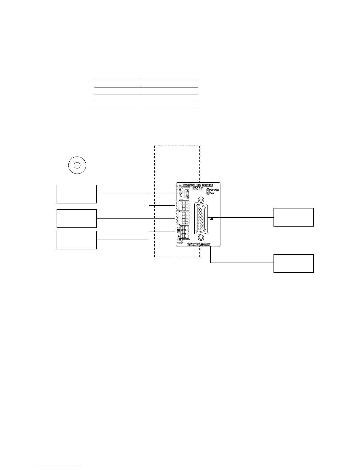
1.3 System Configuration
A sample system configuration using the CM10 is provided below.
Immediate Motion Creator
for CM/SCX Series
(Included)
USB or RS-232C
24 VDC
CANopen
I/O signal
Driver
PC, PLC
(USB or RS-232C)
PC, PLC
(CANopen)
24 VDC
Power supply
External encoder
PLC, Switch, Sensor,
Other device
Page 7
1 Before Use
- 7 -
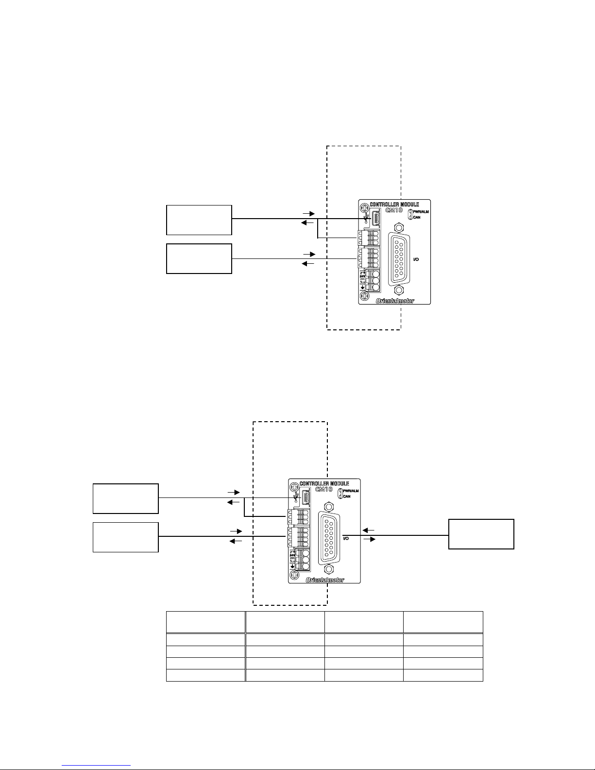
1.4 Operating Methods
There are two ways to make the motor move, immediate command and program execution.
Immediate Command
Operate the motor by sending each command immediately from the master controller such as a computer or
PLC via RS-232C, USB or CANopen. See "7 Start Up (Immediate Command)" on page 42 for more detail.
Driver
(END, ALARM, etc.)
(END, ALARM, etc.)
Immediate command
Immediate command
PC, PLC
(USB or RS-232C)
PC, PLC
(CANopen)
Program Execution
Create sequences using a computer, save the programs into the built-in memory of the CM10, specify which
sequence name or number to run, and input the start signal to execute the sequence. The program creation is
made via USB or RS-232C, the program selection and execution are made via USB, RS-232C, CANopen or I/O
selection. See "9 Program Creation and Execution" on page 87.
Program creation
Program select and
executi on
Program select and
executi on
Program select
and execution
(END, ALARM, etc.)
(END, ALARM, etc.)
(END, ALARM, etc.)
Driver
PC, PLC
(USB or RS-232C)
PC, PLC
(CANopen)
PLC, Switch, Sensor,
Other device
Immediate
Command
Program Creation
Program Select and
Execution
USB
RS-232C
CANopen -
I/O - -
Page 8

1 Before Use
- 8 -
Note
• USB and RS-232C cannot be connected and used at the same time.
• Do not use two or more masters (ex. a CANopen master and a RS-232C master) at the
same time to avoid confusion.
Memo
USB or RS-232C can be used for monitor and maintenance purposes while the CM10 is
being operated by CANopen master.
1.5 Immediate Motion Creator for CM/SCX Series
General terminal software programs (ex. Windows HyperTerminal) can be used for all commands. If you
install the exclusive utility software, Immediate Motion Creator for CM/SCX Series on your PC, just
clicking your mouse can do test operations, program creation, position teaching, parameter setup and I/O
configuration. Real time monitoring of position and feedback, along with I/O status and alarm status are also
provided.
See "6.3 Connecting the USB and Installation of Utility Software" on page 22.
1.6 Standards and CE Marking
The CE Marking (EMC Directive) is affixed to the product is accordance with EN standards.
Installation Conditions (EN Standard)
This product is to be used as a component within other equipment.
Overvoltage category: Ⅰ
Pollution degree: Ⅱ
Protection against electric shock: Class Ⅲ
For EMC Directive
This product has received EMC compliance under the conditions specified in "5.3 Installing and Wiring in
Compliance with EMC Directive" on page 18. The compliance of the final machinery with the EMC Directive
will depend on such factors as the configuration, wiring, layout and risk involved in the control-system
equipment and electrical parts. It therefore must be verified through EMC measures by the customer of the
machinery.
Applicable Standards
EMI Emission Tests
Radiated Emission Test
EN61000-6-4
EN55011 Group1 ClassA
EMS Immunity Tests
Radiation Field Immunity Test
Electrostatic Discharge Immunity Test
Fast Transient / Burst Immunity Test
Conductive Noise Immunity Test
EN61000-6-2
EN61000-4-3
EN61000-4-2
EN61000-4-4
EN61000-4-6
Hazardous Substance
RoHS (Directive 2002/95/EC 27Jan.2003) compliant
Page 9
2 Safety Precautions
- 9 -
2 Safety Precautions
The precautions described below are intended to prevent danger or injury to the user and other personnel
through safe, correct use of the product.
Use the product only after carefully reading and fully understanding these instructions.
Warning
Handling the product without observing the instructions that accompany a "Warning"
symbol may result in serious injury or death.
Caution
Handling the product without observing the instructions that accompany a "Caution"
symbol may result in injury or property damage.
Note
The items under this heading contain important handling instructions that the user
should observe to ensure safe use of the product.
Memo
This contains information relative to the description provided in the main text.
Warning
General
•
Do not use the product in explosive or corrosive environments, in the presence of flammable gases, locations
subjected to splashing water, or near combustibles. Doing so may result in fire or injury.
•
Assign qualified personnel the task of installing, wiring, operating/controlling, inspecting and
troubleshooting the product. Failure to do so may result in fire or injury.
•
Do not transport, install the product, perform connections or inspections when the power is on.
Always turn the power off before carrying out these operations. Failure to do so may result in electric shock.
•
When the device’s protective function is triggered, first remove the cause and then clear the protective
function. Continuing the operation without determining the cause of the problem may cause malfunction of
the device, leading to injury or damage to equipment.
Installation
•
Install the device in an enclosure in order to prevent injury.
Connection
•
Keep the device’s input-power voltage within the specified range to avoid fire.
•
For the device’s power supply use a DC power supply with reinforced insulation on its primary and
secondary sides. Failure to do so may result in electric shock.
•
Connect the cables securely according to the wiring diagram in order to prevent fire.
Operation
•
Turn off the device power in the event of a power failure, or the motor may suddenly start when the power is
restored and may cause injury or damage to equipment.
Repair, Disassembly and Modification
•
Do not disassemble or modify the device. This may cause injury. Refer all such internal inspections and
repairs to the branch or sales office from which you purchased the product.
Page 10

2 Safety Precautions
- 10 -
Caution
General
•
Do not use the device beyond its specifications, or injury or damage to equipment may result.
Transportation
•
Do not hold the device cable. This may cause damage or injury.
Installation
•
Keep the area around the device free of combustible materials in order to prevent fire or a skin burn (s).
Conneciton
•
When grounding the positive terminal of the power supply, do not connect any equipment (PC, etc.) whose
negative terminal is grounded. Doing so may cause the driver and PC to short, damaging both.
Operation
•
To avoid injury, remain alert during operation so that the device can be stopped immediately in an emergency.
•
Before supplying power to the device, turn all start inputs to the device to "OFF." Otherwise, the device may
start suddenly and cause injury or damage to equipment.
•
When an abnormality is noted, stop the operation immediately, or fire or injury may occur.
Disposal
•
When disposing of the device, treat it as ordinary industrial waste.
Page 11

3 Precautions for Use
- 11 -
3 Precautions for Use
This section covers limitations and requirements the user should consider when using this product.
Preventing Electrical Noise
See "5.3 Installing and Wiring in Compliance with EMC Directive" on page 18 for measures with regard to
noise.
EEPROM Write Cycle
Do not turn off the 24 VDC power supply while data is being written to the EEPROM and 5 seconds after the
completion of data write. Doing so may abort the data write and cause an EEPROM error alarm to generate.
The EEPROM can be rewritten approx. 100,000 times.
Temperature Rise
The CM10 is carefully designed so that the installation of the CM10 does not affect the temperature rise in the
driver. However, greater temperature rise in the driver may occur depending on the conditions such as airflow.
Changing the operating/environmental condition may be required
Page 12

4 Preparation
- 12 -
4 Preparation
4.1 Checking the Product
Product Name CM10-1 CM10-1A CM10-2 CM10-3 CM10-3A CM10-4 CM10-5
Controller Module Name CM10-1 CM10-2 CM10-3 CM10-4 CM10-5
CD-ROM
- IMC (utility software)
- Startup manual
- Operating manual
- CANopen EDS file
- USB driver
- .NET Framework 2.0
Connector set
・RS-232C connector (3 pins): 1
・CANopen connector (4 pins): 1
・Power connector (3 pins): 1
Encoder connector housing
/contact (8 pins)
Mounting plate set
・Mounting bracket: 1
For
CM10-1
For
CM10-1A
For
CM10-2
For
CM10-3
For
CM10-3A
For
CM10-4
For
CM10-5
・M2.6, Pan head screw
with spring washer: 2
-
・M3, Flat head screw: 1 - - - - - -
・Tape fastener: 1 25.4 mm
width
22 mm
width
15 mm
width
25.4 mm
width
25.4 mm
width
22 mm
width
25.4 mm
width
Startup manual HP-13010 HP-13011 HP-13012 HP-13025 HP-13026
Warning sticker - - - - -
4.2 How to Identify the Product Model
CM10 - 1
1 : For AR Series (AC input type), NX Series (50 to 200 W)
For Motorized Actuators with LSD-A, LSD-C, LSD-S drivers
1A : For AR Series (DC input type)
For Motorized Actuators with LSD-K drivers
2 : For RBK Series
3 : For Motorized Actuators with ESMC driver (AC input type)
3A: For Motorized Actuators with ESMC driver (DC input type)
4 : For AS/ARL Series, Motorized Actuators with AS/ARL driver
5 : For NX Series (400 to 750 W)
Controller Module CM10 Series
Page 13

4 Preparation
- 13 -
4.3 Combinations of CM10 and Drivers
Product
Model
Controller Module
Model
Driver Model
CM10-1 ARD-A, ARD-C, ARD-S
LSD-A, LSD-C, LSD -S
NXD20-A, NXD20-C
CM10-1A
CM10-1
ARD-K
LSD-K
CM10-2 CM10-2 RBD215A-K, RBD228A-K, RBD242A-V, RBD245A-V
CM10-3 ESMC-A2, ESMC-C2
CM10-3A
CM10-3
ESMC-K2
CM10-4 CM10-4 ASD13A-A, ASD13B-A, ASD13C-A
ASD24A-A, ASD24B-A, ASD24C-A
ASD30A-A, ASD30B-A, ASD30C-A, ASD30D-A, ASD30E-A
ASD12A-C, ASD12B-C, ASD12C-C
ASD16A-C, ASD16B-C, ASD16C-C, ASD16D-C
ASD20A-C
ASD12A-S, ASD12B-S, ASD12C-S
ASD16A-S, ASD16B-S, ASD16C-S, ASD16D -S
ASD20A-S
ARLD13A-A, ARLD13B-A, ARLD13C-A
ARLD24A-A, ARLD24B-A, ARLD24C-A
ARLD30A-A, ARLD30B-A, ARLD30C-A, ARLD30D-A, ARLD30E-A
ARLD07A-C, ARLD07B-C, ARLD07C-C
ARLD12A-C, ARLD12B-C, ARLD12C-C
ARLD16A-C, ARLD16B-C, ARLD16C-C, ARLD16D-C, ARLD20A-C
ARLD07A-S, ARLD07B-S,
ARLD07C-S
ARLD12A-S, ARLD12B-S, ARLD12C-S
ARLD16A-S, ARLD16B-S, ARLD16C-S, ARLD16D-S
ARLD20A-S
LSD20A-S, LSD20A-W, LSD20B-S, LSD20B-W
CM10-5 CM10-5 NXD75-S
Note
The NX Series driver can be used only in the position control mode.
Page 14
4 Preparation
- 14 -
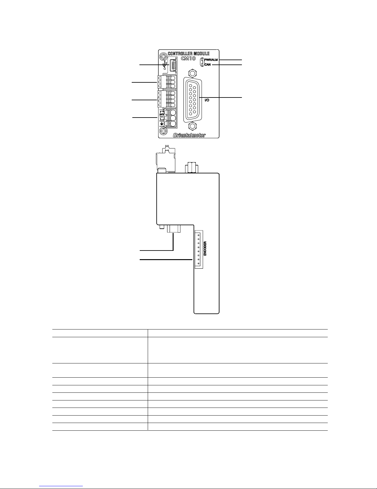
4.4 Names and Functions of Parts
POWER/ALARM LED
CANopen LED
CANopen connector
Power connector
I/O connector
RS-232C connector
Driver connector
Encoder connector
USB connector
Name Description
POWER/ALARM LED (green/red) Green: Lit when the power is on.
Red: The LED blinks when a protective function is triggered. The cause triggering
the protective function can be identified by the number of blinks the LED
emits. See "13 Troubleshooting" on page 338.
CANopen LED (green/red) Green: Run
Red: Error (See "10.3 LED Indication" on page 104 for detail.)
Power connector Connects to the power supply cable
I/O connector Connects to the sensors, switches and/or master controller
RS-232C connector Connects to the RS-232C cable
USB connector Connects to the USB2.0 cable (mini-B type)
CANopen connector Connects to the CANopen cable
Encoder connector Connects to the external encoder
Driver connector Connects to the driver
Page 15
5 Installation
- 15 -
5 Installation
5.1 How to Install CM10 on the Driver
Note
• See each driver operating manual for the following instructions.
• Before installing the CM10-1, 3, 4, 5 are sure to set the driver pulse mode switch according to the
pulse mode on the CM10. The factory setting of CM10-1, 3, 4, 5 is 1 pulse mode.
• Because the step angle switch on the driver will be partially covered by the CM10-2, it is
recommended that to set the step angle before installing the CM10-2.
• For use of the CM10-3, the ESMC controller should be set to the "driver mode." If the ESMC controller
is used in the "controller mode (factory setting)," unexpected motion may occur due to unmatched I/O
assignments.
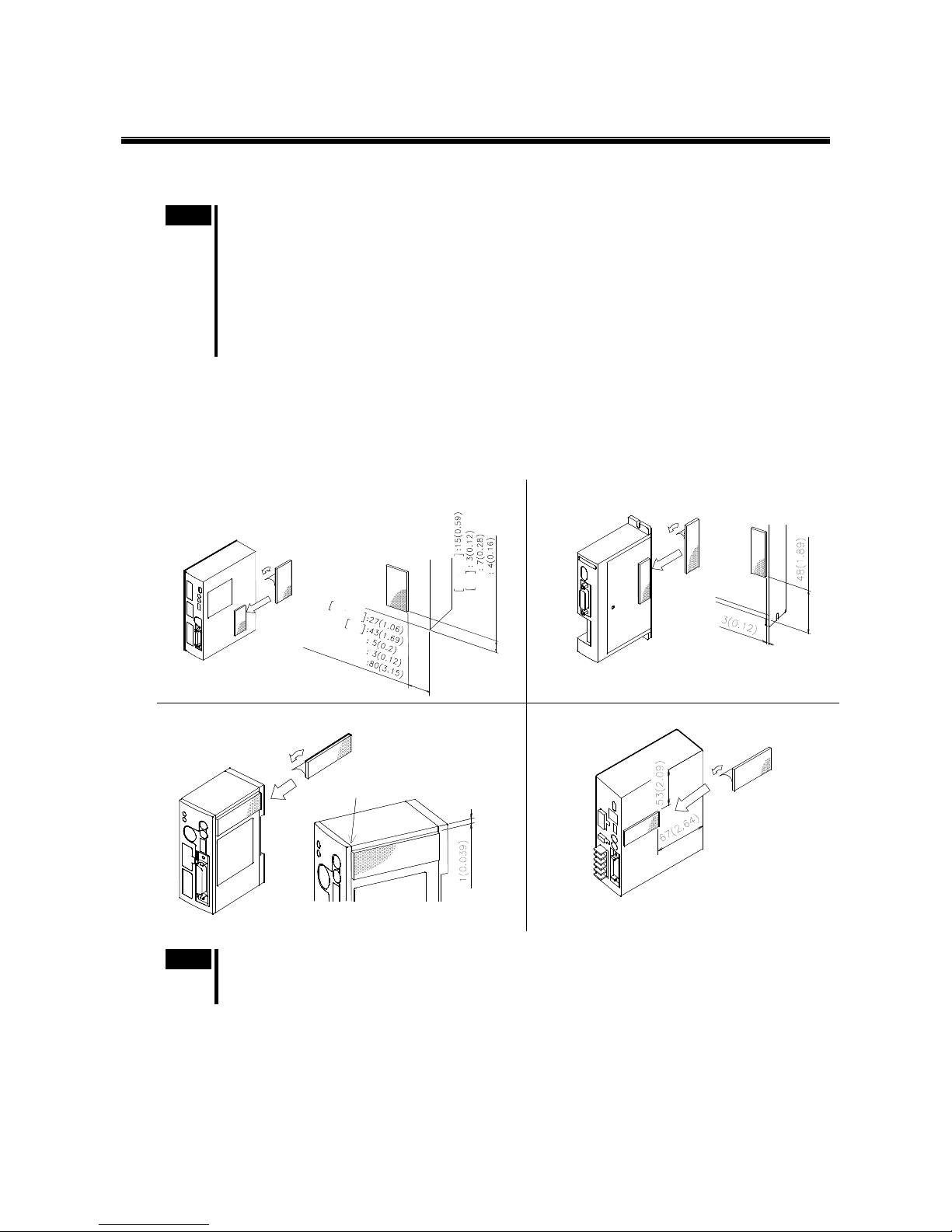
1.
Attaching the tape fastener to the driver
a. Remove grease from the pasting position on the driver surface with alcohol and a cloth.
b. Peel off the red delaminating tape.
Paste the tape fastener well on the driver being careful not to bend or crease the tape. The other part of the tape fastener is
attached to the mounting bracket before shipping. Unit: mm (inch)
• CM10-1, 3, 3A, 5 • CM10-2
C
M
1
0
-
1
A
R
L
S
D
C
M
1
0
-
5
C
M
1
0
-
3
A
C
M
1
0
-
3
C
M
1
0
-
1
N
X
C
M
1
0
-
1
A
R
L
S
D
C
M
1
0
-
1
N
X
C
M
1
0
-
3
,
3
A
C
M
1
0
-
5
• CM10-1A
•
CM10-4
Note
Do not apply any peeling force that may influence the adhesive surface immediately after adhesion. The
adhesive strength gradually increases and reaches its maximum in 72 hours. For the best results, allow
one day or more after adhesion, and then go to next step of assembly.
Mate the left edge of tape
fastener with the bump
on the driver surface.
Page 16
5 Installation
- 16 -
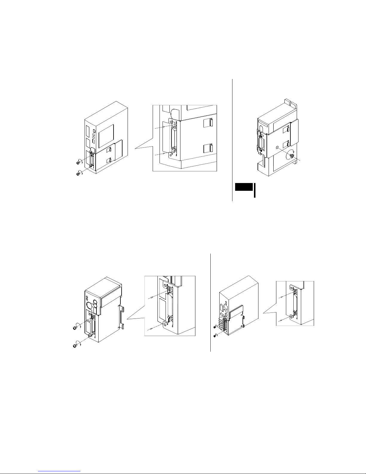
2.
Mounting the mounting bracket
• CM10-1, 2, 3, 3A, 5
a. Set the mounting bracket over the I/O terminal of the driver, and tighten the mounting bracket with the 2 screws provided.
(Only 1 screw for CM10-2)
b. Push the mounting bracket to mesh the two parts of the tape fastener together.
• CM10-1, 3, 3A, 5
Tightening torque: 0.4 N・m (M2.6)
• CM10-2
Tightening torque: 0.5 N・m (M3)
Note
Do not use a screw other
than the supplied screw.
• CM10-1A, 4
a. Set the mounting bracket over the I/O terminal of the driver so as to mate the screw holes, and push the mounting bracket to
mesh the two parts of the tape fastener together. (For ease of mating the screw holes, lightly twist two screws in before
meshing the tape fasteners together. Do not tighten them at this point.)
b. Tighten the mounting bracket with the 2 screws provided.
• CM10-1A
Tightening torque: 0.4 N・m (M2.6)
• CM10-4
Tightening torque: 0.4 N・m (M2.6)
Page 17
5 Installation
- 17 -
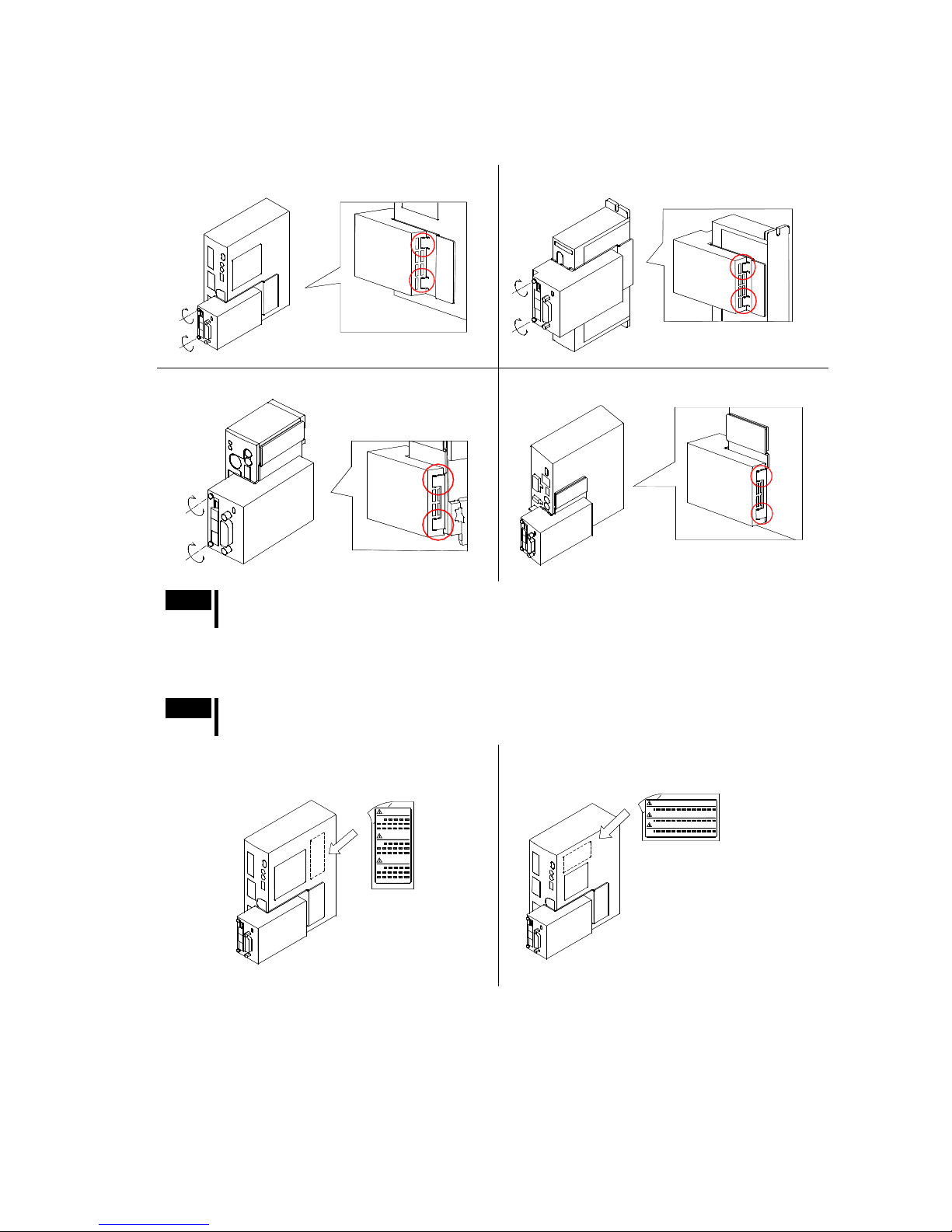
3.
Mounting CM10 on the mounting bracket
a. Put the rails of the mounting bracket in the slits of the CM10, insert the connector of the CM10 into the driver connector
on the CM10.
b. Tighten the two screws on top of the CM10 into the mounting bracket. ∗ Tightening torque: 0.4 N・m (M2.6)
• CM10-1, 3, 3A, 5 • CM10-2
• CM10-1A • CM10-4
Note
Be sure that the CM10 is not powered ON when it is installed to, or uninstalled from the driver. The
installation or uninstallation with powered ON may damage the interface circuit in the CM10.
4.
Paste the warning sticker on the driver (only for AR Series driver AC input type/LSD driver AC input type and NX
Series driver)
Note
Be sure to paste an attached new warning sticker since the warning sticker on the AR Series driver/LSD
driver or NX Series driver is covered by the CM10.
• AR Series driver (AC input type)
• LSD driver (AC input type)
• NX Series driver
WARNING
AVERTISSEMENT
警 告
WARNING
AVERTISSEMENT
警 告
This completes the installation.
Please confirm that the controller module is mounted securely and that no miss-alignment or gaps exist.
Page 18
5 Installation
- 18 -
Memo
When removing the CM10, unscrew the two screws on top of the CM10 only a few turns just enough to
release it from the bracket and leave the screws as they are in the CM10. Unscrewing any more may
cause the screws to not protrude out of the housing holes.
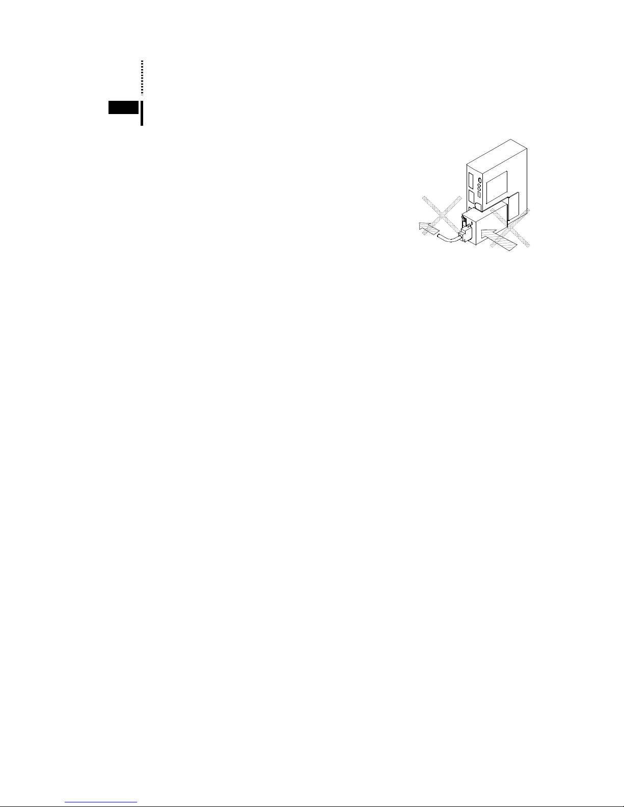
Note
Always avoid applying a force toward the left direction on the I/O cable or the front panel. It may cause
breaking the adhesion of the tape fastener.
5.2 Installing the Driver
Refer to the driver’s Operating Manual and install it at an appropriate distance from other equipment
5.3 Installing and Wiring in Compliance with EMC Directive
This device has been designed and manufactured for incorporation in general industrial machinery. The EMC
Directive requires that the equipment incorporating this product comply with the directive.
The installation and wiring method for the motor and device are the basic methods that would effectively allow
the customer’s equipment to be compliant with the EMC Directive.
The compliance of the final machinery with the EMC Directive will depend on such factors as configuration,
wiring, layout and risk involved in the control-system equipment and electrical parts. It therefore must be
verified through EMC measures by the customer of the machinery. For the EMC Directives, see "1.6 Standards
and CE Marking" on page 8.
Connecting Mains Filter for Power Source Line
Install a mains filter on the input side of the DC power supply in order to prevent the noise generated within
the driver from propagating outside via the DC power-source line.
•
Install the mains filter as close to the AC input terminal of the DC power source as possible, and use cable
clamps and other means to secure the input and output cables (AWG18: 0.75 mm
2
or more) firmly to the
surface of the enclosure.
•
Connect the ground terminal of the mains filter to the grounding point, using as thick and short a wire as
possible.
•
Do not place the AC input cable (AWG18: 0.75 mm2 or more) parallel with the mains filter output cable
(AWG18: 0.75 mm
2
or more). Parallel placement will reduce mains filter effectiveness if the enclosure’s
internal noise is directly coupled to the power-supply cable by means of stray capacitance.
Connecting the 24 VDC Power Supply
Use a 24 VDC power supply conforming to the EMC Directive.
Use a shielded cable for wiring and wire/ground the 24 VDC power supply over the shortest possible distance.
Refer to "Wiring the Power Supply Cable and I/O Signals Cable" below for how to ground the shielded cable.
How to Ground
The cable used to ground the driver, motor and mains filter must be as thick and short as possible so that no
potential difference is generated. Choose a large, thick and uniformly conductive surface for the grounding
point.
Page 19
5 Installation
- 19 -
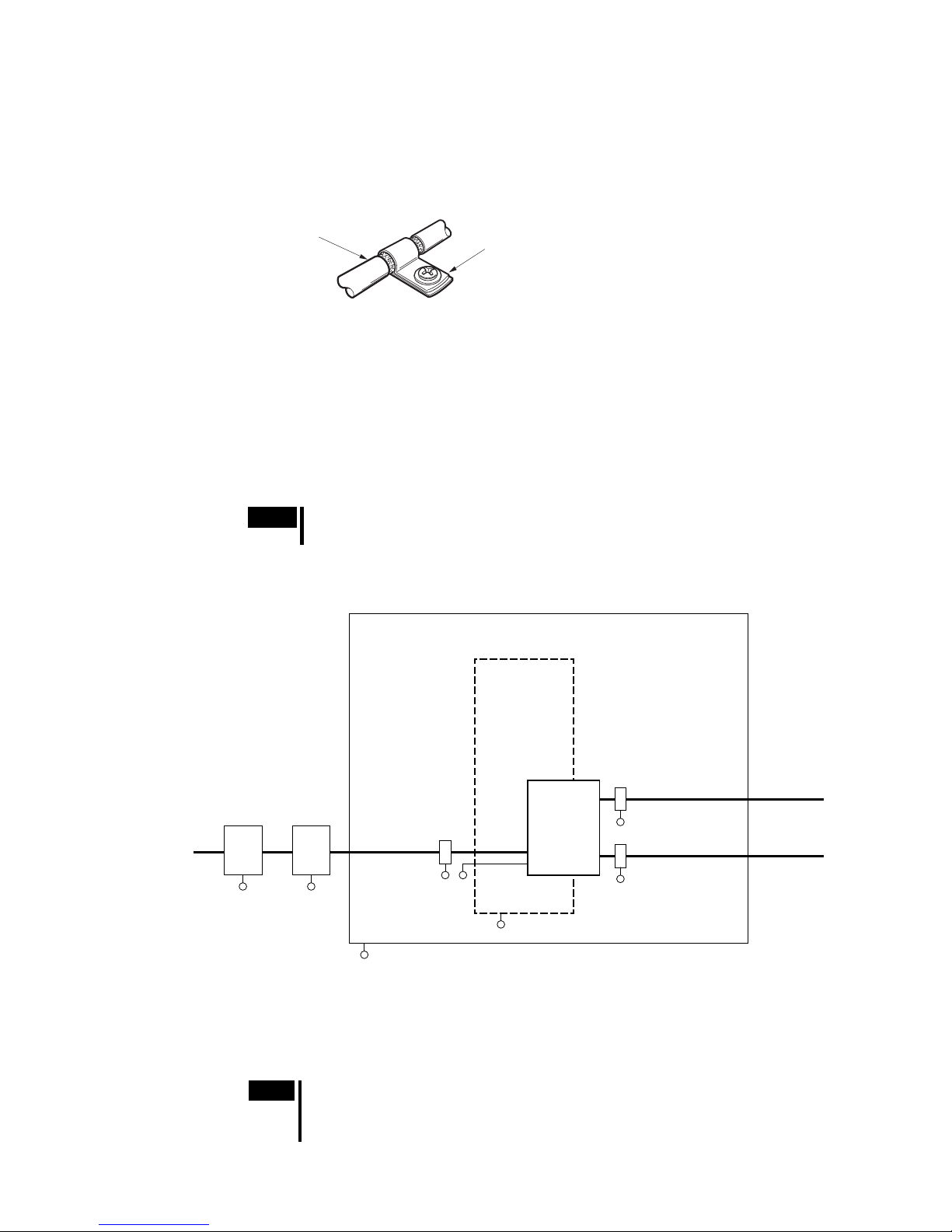
Wiring the Power Supply Cable and I/O Signals Cable
Use a shielded cable of AWG24 (0.2 mm2) or more for the power supply cable and signal cable, and keep it as
short as possible.
To ground a shielded cable, use a metal clamp or similar device that will maintain contact with the entire
circumference of the shielded cable. Attach a cable clamp as close to the end of the cable as possible, and
connect it as shown in the figure.
Cable clamp
Shield cable
Notes about Installation and Wiring
•
Connect the motor, driver and other peripheral control equipment directly to the grounding point so as to
prevent a potential difference from developing between grounds.
•
When relays or electromagnetic switches are used together with the system, use mains filters and CR circuits
to suppress surges generated by them.
•
Keep cables as short as possible without coiling and bundling extra lengths.
•
Place the power cables such as the motor and power supply cables as far apart [100 to 200 mm (3.94 to 7.87
in.)] as possible from the signal cables. If they have to cross, cross them at a right angle. Place the AC input
cable and output cable of a mains filter separately from each other.
Note
Be sure to connect the protective earth lead wire of the motor cable to the protective earth
terminal of the driver. If not connected, an error via USB communication may occur.
Example of CM10 Module and Driver Installation and Wiring
Driver
CM10
Master
controller
I/O cable
(Shielded cable)
Power supply cable
(Shielded cable)
DC Power
supply
Mains
filter
CANopen cable
(Shielded cable)
FG
FG
FG
Grounded panel
PE
A
C
PE PE
PE
Master
controller
FG
Precautions about Static Electricity
Static electricity may cause the CM10 to malfunction or suffer damage. While the CM10 is receiving power,
handle the CM10 with care and do not come near or touch the CM10.
Note
The CM10 uses parts that are sensitive to electrostatic charge. Before touching the CM10,
turn off the power to prevent electrostatic charge from generating.
If an electrostatic charge is impressed on the CM10, the CM10 may be damaged.
Page 20
6 Connection
- 20 -
6 Connection
This chapter explains the methods for connecting to the computer, PLC, sensors, switches, external encoder,
and the power supply, as well as the grounding method, connection examples and control inputs/outputs.
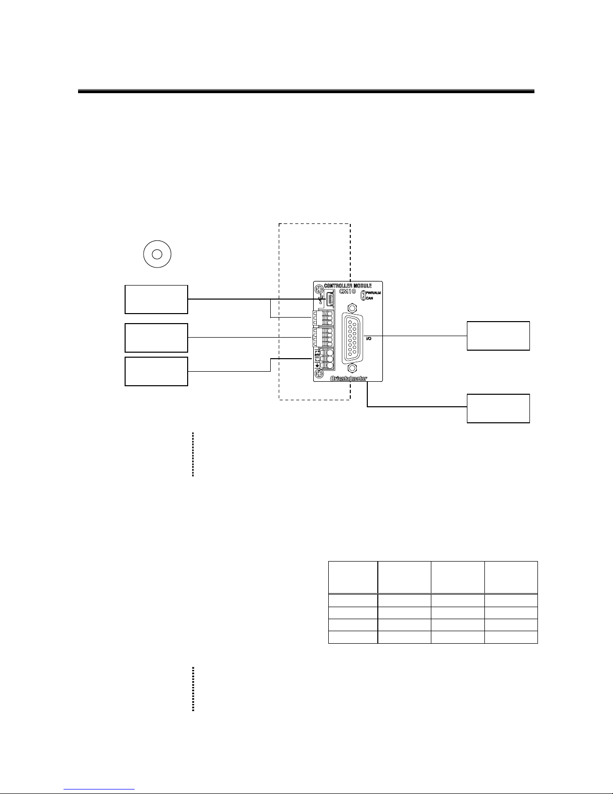
6.1 Overview
System Configuration
A sample system configuration using the CM10 is provided below.
Immediate Motion Creator
for CM/SCX Series
(Included)
USB or RS-232C
24 VDC
CANopen
I/O signal
Driver
PC, PLC
(USB or RS-232C)
PC, PLC
(CANopen)
24 VDC
Power supply
External encoder
PLC, Switch, Sensor ,
Other device
Memo
• Making all connections is not necessary. Choose the necessary connections according
to your needs by referring the contents and the chart below.
• For the initial set up, only a power supply and a computer (USB or RS-232C connection)
are required. See "7 Start Up (Immediate Command)" on page 42.
Contents
6.2 Connecting the Power Supply
6.3 Connecting the USB and Installation of Utility Software
6.4 Connecting the I/O Signals
6.4.1 Pin Assignments Interface and Availability
6.4.2 Input Signals
6.4.3 Output Signals
6.4.4 Connection Example of I/O
6.5 Driver I/O Setting (CM10-1 and
CM10-3)
6.6 Connecting the RS-232C
6.7 Connecting the CANopen
6.8 Connecting the External Encoder
Memo
The CM10 is designed so that users can operate drivers without needing to know the
connections between the CM10 and the driver. However, the pin assignments and signal
descriptions for the connector driver are provided for users who are familiar with the driver
terminal functions. See "Appendix A Signals for Driver" on page 351.
Immediate
Command
Program
Creation
Program
Select and
Execution
USB
RS-232C
CANopen -
I/O - -
Page 21
6 Connection
- 21 -
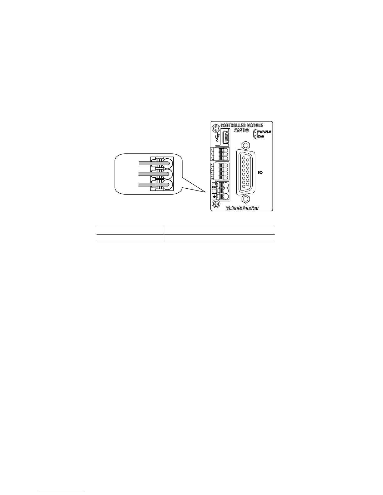
6.2 Connecting the Power Supply
Connecting to the Power Supply
Use the power supply connector (3 pins) to connect the power supply cable (AWG24 to 16: 0.2 to 1.5 mm2) to
the main power supply connector on the CM10.
Grounding CM10
Ground the driver’s Frame Ground Terminal (FG) as necessary.
Use a grounding wire of a size equivalent to or larger than the power-supply cable (AWG24 to 16: 0.14 to 1.5
mm
2
).
+24VDC
FG
GND
Applicable Lead Wire
Connector FMC 1,5/3-ST-3,5 (PHOENIX CONTACT)
Applicable lead wire size AWG24 to 16 (0.2 to 1.5 mm2)
Connection Method
1.
Strip the lead wire insulation by 10 mm.
2.
Push the spring (orange) of the connector with a flat-tip screwdriver, to open a terminal port.
Recommended flat-tip screwdriver: a tip of 2.5 mm in width, 0.4 mm in thickness
3.
Insert the cable while pushing down the flat-tip screwdriver.
4.
Release the flat-tip screwdriver. The lead wire will be attached.
Page 22

6 Connection
- 22 -
6.3 Connecting the USB and Installation of Utility Software
The USB connection can be used for all the operations including initial setup, test operation, program creation,
I/O configuration and real time monitoring, using general terminal software or supplied utility software as well
as user program. Everything you can perform via USB can also be performed via RS-232C.
Specification
∗ The USB on the CM10 talks to the virtual COM port on the computer.
Item Description
Electrical characteristics In conformance with USB2.0 (Full Speed)
Transmission method Start-stop synchronous method, NRZ (Non-Return Zero), full-duplex
Data length 8 bits, 1 stop bit, no parity
Transmission speed 9600, 19200, 38400, 57600, 115200 bps (9600 is factory setting.)
Selected by the USBBAUD parameter
Protocol TTY (CR+LF)
Terminal Specification
•
ASCII mode
•
VT100 compatible recommended
•
Handshake: None
•
Transmission CR: C-R
•
Word wrap: None
•
Local echo: None
•
Beep sound: ON
Conncector
•
USB mini-B
Note
Be aware that Windows automatically changes the COM port number when a CM10 is
replaced.
Memo
Generally, the maximum number of COM ports in a Windows PC is 256. Since the COM
port number on a PC increases every time different CM10 is connected via USB, setting
data to more than 256 pieces of CM10 cannot be accomplished using a PC. When it is
required such as for mass production, use RS-232C connection or USB to RS-232C
converter so as to be RS-232C connection on the CM10.
USB Driver Installation
Insert the supplied CD-ROM into the CD-ROM drive of the computer, power on the CM10 and connect to a
USB port using a mini-B cable. (Prepare a commercially available USB2.0 cable (mini-B type). A cable with
ferrite cores that has the effect of exogenous noise suppression is recommended.) You will then be asked to
install the USB driver. See the procedure according to the type of Windows as follows.
Windows 7:
1. Open "Devices and Printers" in the control panel.
2. Right click on "FT232R USB UART" and select "Update Driver Software."
3. Select "Browse my computer for driver software."
4. Click "Browse" and select the applicable CD-ROM drive, check the box next to "Include subfolders" and
Click "Next."
5. After successful installation, click "Close."
6. Go back to the Device Manager, right click on "USB Serial Port" and select "Update Driver Software."
Repeat same procedure as the above FT232R USB UART installation.
Windows Vista:
1. The installation of the FT232R USB UART is asked by Windows when the CM10 is connected. Select
"Locate and install driver software," and click "Next." After successful installation, click "Close."
2. The installation of the USB Serial Port is then asked for by Windows.
3. Click "Next." After successful installation, click "Close."
Page 23

6 Connection
- 23 -
Windows XP:
1. The installation of the FT232R USB UART is asked for by Windows when the CM10 is connected. Select
"Install the software automatically," and click "Next." After successful installation, click "Finish."
2. The installation of the USB Serial Port is then asked for by Windows. Select "Install the software
automatically," and click "Next."
3. After successful installation, click "Finish."
Installation of Utility Software "Immediate Motion Creator for CM/SCX
Series (IMC)"
While all commands for the CM10 can be made using general terminal software, the supplied Windows based
utility software, Immediate Motion Creator for CM/SCX Series (IMC), gives you instant operation, easy
programming and configuration without having to know any commands. Since important settings and functions
(such as I/O assignment, automatic setting of the driver I/O, etc.) are included, it is recommended to use the
IMC.
Functions:
•
Motion Creator: Select motion type, put desired values in and click the start button to begin motions instantly.
•
Program Editor: Double click listed commands in a desired order to create a sequence program, and click a
button to save it to the device or your PC.
•
Terminal: Use as a general terminal software. Most commands can be used by typing.
•
Teach/Jog: Move motors and store positions. Stored positions can be used for programmed motions.
•
System Config: Indicate and Set system parameters and I/O assignments
•
Real Time Monitor: I/O, Alarms (including history), Busy, Motor Position and Encoder Position
• System Requirements
- Windows XP SP2 or later, Windows Vista, Windows 7
- .NET Framework 2.0
- SVGA monitor 800 x 600 or greater
- USB or RS-232C port
- CD-ROM drive
• Installation and Uninstallation
Insert the supplied CD-ROM into your CD-ROM drive. Open the Explorer, select the applicable CD-ROM
drive, open the IMC folder, double click on "setup.exe" and follow the on screen instructions.
To uninstall, use the "Add/Remove Programs" function in the Windows Control Panel.
Note
When updating the installed version of the IMC, do so when the existing IMC is not running.
• .NET Framework 2.0 Installation (For Windows XP)
IMC runs on the Microsoft .NET Framework 2.0. While Windows Vista and Windows 7 normally install
the .NET Framework 2.0, Windows XP requires a separate installation. If the .NET Framework 2.0 is not
installed on the computer, install it prior to the IMC installation. The .NET Framework 2.0 software is on the
supplied CD-ROM, under the DotNet_Framework2_0 folder.
System Requirements for .NET Framework 2.0
- Supported Operating Systems: Windows XP SP2 or later
- Disk Space: 280 MB (x86)
Visit the Microsoft .NET 2.0 Framework website if detailed information is required.
• Start
1. Connect the CM10 by USB2.0 cable (mini-B type)
2. Power on the CM10
3. Click "Start" - "All Programs"- "ORIENTAL MOTOR" - "IMC for CM SCX" - "Immediate Motion Creator
for CM SCX Series." The COM port selection window will appear.
4. Select the COM port that is connected to the CM10. The IMC will be launched.
The IMC is made to be intuitive to use. For instructions, refer to the HELP menu in the IMC, as necessary.
Right click on the IMC screen and select [Help] will launch the IMC Help with the description of function that
the mouse cursor is on.
Page 24

6 Connection
- 24 -
• Update
After installation, click "Help" - "Check New Version" on the pull down menu with the Internet connection. If a
newer version of this software is available, continue to the download and update actions.
• About VERBOSE and ECHO
The IMC may alter automatically the ECHO (Echo ON/OFF) and VERBOSE (respond with data and
description/respond with data only) parameters of the CM10 for communications and ease of use. The ECHO
and VERBOSE parameters cannot be set in the System Config window on the IMC. When changing the ECHO
and/or VERBOSE setting is required, follow the procedure below.
1. Turn on the power to the CM10
(If the message of reconnection attempt failure has shown while using the IMC, first turn off the power,
wait for a few seconds and restart.)
2. Launch the IMC software
3. Click the [Terminal] tab
4. Type "ECHO=0" or "ECHO=1", press the Enter key and "VERBOSE=0" or "VERBOSE=1", then press
the Enter key (both parameters must be typed)
5. Type "SAVEPRM" and press the Enter key, then type "Y" and press the Enter key
6. After "OK" is indicated, exit the IMC (Do not operate other functions before exiting)
7. Turn off the power to the CM10 for the new settings to become effective
Setting the Baud Rate
Since the USB on the CM10 talks to the virtual COM port on the computer, the baud rate for the COM port and
the baud rate for the CM10 need to be the same.
The default USB baud rate of the CM10 is 9600 bps, same as the default baud rate of a general Windows
computer. If the baud rate on the computer or the CM10 is changed, the baud rate must also be changed on the
other.
• When Using the IMC, Provided Utility Software
Use of the highest baud rate, 115200 bps is recommended if there is no problem for the usage environment. Set
it to the CM10 according to the following steps.
1. Turn on the power for the CM10 and connect to the computer.
2. Launch the IMC.
3. Click the [System Config] tab.
4. Click the "USB Baud rate "located at the upper-center, and select "115200 bps" from the drop-down list.
5. Click the [SAVE and RESET] to enable the change. At that time, the IMC also change the baud rate of
computer side to 115200 bps.
The setting is completed. The CM10 is already communicating with your computer at 115200 bps.
Note
When starting communication with the CM10, be sure to set the baud rate of the IMC to
the same baud rate that has been set to the CM10. If you are unsure about the baud rate
of the CM10, use the [Scan Baud Rate] button on the Serial Port Settings window. If the
wrong baud rate has been set in the Serial Port Settings window, not only will the
communication not be established, but it may also be possible that the communication will
never be established even if the baud rate is correctly set afterwards. If this
communication problem occurs, turn off the power to the CM10, wait for a few seconds
and restart. Take the same action any time when communication is likely to be
disconnected.
• When Using Other Software than the IMC
- The Computer:
Check the baud rate of the computer application that is used to communicate with the CM10, or check the
COM port property of Windows if the application does not have the baud rate function.
- The CM10:
The USBBAUD is the command used to change the baud rate for the USB connection. Always set the
CM10 baud rate first, then set the baud rate on the master to the same baud rate.
Page 25
6 Connection
- 25 -
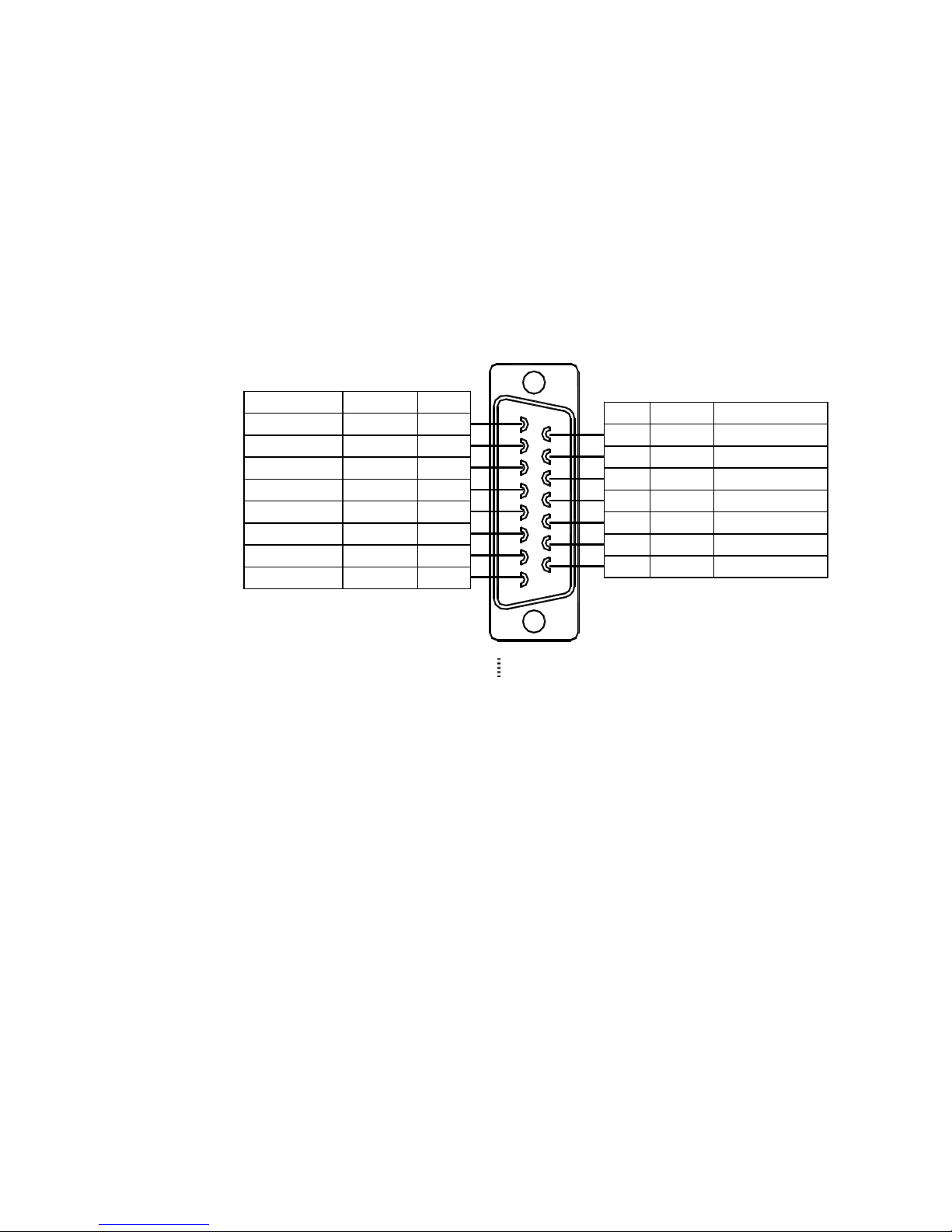
6.4 Connecting the I/O Signals
Connect the PLC, switch, sensor etc. to the I/O connector (D-sub connector on the front panel of the CM10).
6.4.1 Pin Assignments
At the time of shipment, any signals that have specific functions are not assigned to the I/O connector, which
functions as general input "IN1 to IN9" and general output "OUT1 to OUT4." As necessary, assign signals and
connect accordingly (The connector is not supplied. Provide 15 Pin D-Sub connector separately). Those
become "system xxx signal."
Connector Function Table
See the following pin assignments for a solder type connector.
14 OUT2 General output
15 OUT4 General output
Pin No. Signal
9IN1
10 IN3
11 IN5
12 IN7
13 IN9 General i nput
General input
General input
General input
General input
Description
Output common OUT-COM 8
General output OUT1 6
General output OUT3 7
General input IN6 4
General input IN8 5
General input IN2 2
General input IN4 3
Description Signal Pin No.
Input common IN-COM 1
Memo
The connector shell is connected to the FG terminal.
Page 26
6 Connection
- 26 -
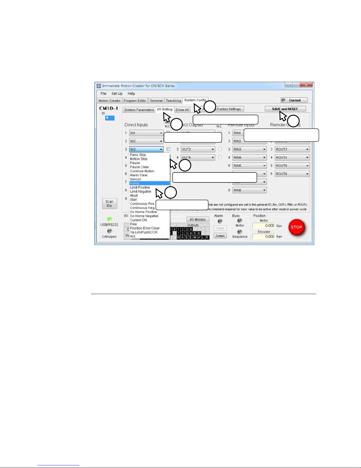
Assigning Signals
Assign necessary signals to the I/O using the provided utility software, Immediate Motion Creator for
CM/SCX Series (IMC).
Connect the CM10 to a computer and activate the IMC. Connect the CM10 to a computer, launch the IMC and
follow the steps below.
The setting can also be performed by command input, using the terminal mode of IMC or general terminal
software. See the following chart for the command for assignment and logic level. After executing command,
enter "SAVEPRM" and press the Enter key to save the parameter. New value becomes active after reset or
power cycle.
• Input
Signal Command for Assignment Command for Logic Level Setting
PSTOP (panic stop)
MSTOP (motor stop)
SENSOR (sensor)
PAUSE (pause motion)
PAUSECL (pause clear)
CONT (continue motion)
LSP (limit switch positive)
LSN (limit switch negative)
HOME (home sensor)
CON (current on)
ALMCLR (alarm clear)
START (start sequence)
ABORT (abort motion and sequence
execution)
MCP (move continuously positive)
MCN (move continuously negative)
MGHP (move go home positive)
MGHN (move go home negative)
FREE (current off, magnetic brake free)
PECLR (p
osition error clear)
TL (torque limiting/push-motion operation)
INPSTOP
INMSTOP
INSENSOR
INPAUSE
INPAUSECL
INCONT
INLSP
INLSN
INHOME
INCON
INALMCLR
INSTART
INABORT
INMCP
INMCN
INMGHP
INMGHN
INFREE
INPECLR
INTL
PSTOPLV
MSTOPLV
SENSORLV
PA US E LV
PAUSECLLV
CONTLV
OTLV
OTLV
HOMELV
CONLV
ALMCLRLV
STARTLV
ABORTLV
MCPLV
MCNLV
MGHPLV
MGHNLV
FREELV
PECLRLV
TLLV
Click the [System Config] tab
Click the [I/O Setting] tab
Select the desired signal
Check when setting to "normally closed"
Click [SAVE and RESET] and the
change will become effective
2
1
3
4
5
Page 27
6 Connection
- 27 -
• Output
Signal Command for Assignment Command for Logic Level Setting
ALARM (alarm)
END (motion end)
RUN (sequence running)
MOVE (motor moving)
READY (operation ready)
LC (limiting condition)
PSTS (pause status)
HOMEP (home position)
MBFREE (magnetic brake free)
OUTALARM
OUTEND
OUTRUN
OUTMOVE
OUTREADY
OUTLC
OUTPSTS
OUTHOMEP
OUTMBFREE
ALARMLV
ENDLV
RUNLV
MOVELV
READYLV
LCLV
PSTSLV
HOMEPLV
-
The following example is a command to assign the FREE input to the IN3 and set to "normally closed."
>INFREE=3
>FREELV=1 (0: Normally Open, 1: Normally Closed)
>SAVEPRM
>RESET
6.4.2 Input Signals
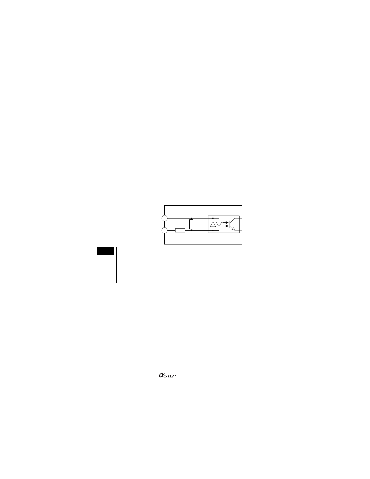
Internal Input Circuit
All input signals of the device are photo coupler inputs. The signal state represents the "ON: Carrying current"
or "OFF: Not carrying current" state of the internal photo coupler rather than the voltage level of the signal.
5.4 kΩ
10 kΩ
1
IN-COM, IN1 to 9
2 to 5, 9 to 13
Internal circuit
Note
• All input signals are "normally open" under the factory settings. When setting the logic
level to "normally closed," ON/OFF will be opposite in the description of the following
signals.
• Set the voltage between IN-COM and INx to be 4.25 VDC to 26.4 VDC when the photo
coupler is ON.
Signals
• IN1-IN9 Input (unassigned)
The IN1 through IN9 inputs can be used as input ports for general signals when they are not assigned to a
specific signal.
The status of each port can be read using an IN command or INx (x=1-9) command, and directly commanded or
used in a sequence program.
A sequence program can be selected by the binary value of the general inputs when a START signal is input.
See "9.6 Executing a Sequence" on page 96.
• PSTOP (panic stop) Input
This signal is used to forcibly stop motion and the sequence. Also the deviation counter in the driver is cleared
for stopping servo motors and
products immediately. The action of the motor current and the alarm
state after the PSTOP operation is determined by the ALMACT command, either alarm or no alarm.
The leading edge of the signal will cause the action.
• MSTOP (motor stop) Input
This signal is used to forcibly stop motion. This command does not stop a sequence program.
While the motor is operating, when MSTOP input is turned ON, the motion will be stopped as configured by the
MSTOPACT command, either hard stop or soft stop.
The leading edge of the signal will cause the action.
Page 28

6 Connection
- 28 -
• SENSOR (sensor) Input
This signal is used for:
- Stopping motion during continuous operation.
- Offset motion on the fly during continuous operation.
- Secondary home input for better accuracy during the mechanical homing operation.
Set the operation (hard stop, soft stop, soft stop at fixed distance from SENSOR signal, no action) using the
SENSORACT command.
The leading edge of the signal will cause the action.
• PAUSE (pause motion) Input
This signal is used to stop motion temporarily. If the PAUSE input is turned ON during any motion, motion is
stopped and the device retains the motion type (positioning, continuous, etc) and remaining distance to the
original target position if the paused operation is a positioning motion.
If CONT command or input is executed, while in a paused situation, the remaining motion will be started.
If START input is turned ON while in a paused situation only during sequence execution, the remaining motion
will be started (STARTACT=0).
Linked motions, return-to-electrical home operation and mechanical home seeking cannot be paused and
resumed: PAUSE causes a soft stop, and CONT is ignored.
If the PAUSECL input is turned ON or the PAUSECLR is commanded, the remaining motion will be canceled.
Only the on-going motion is paused. The program execution will not stop.
The leading edge of the signal will cause the action.
• PAUSECL (pause clear) Input
This signal clears the on-going operation state that has been paused by the input of a PAUSE signal. (The
remaining motion is canceled.)
If this signal is activated while a sequence is running, only remaining portion of the current motion is cleared
and the next step of the sequence will be executed, since the PAUSE does not stop the sequence.
The leading edge of the signal will cause the action.
• CONT (continue motion) Input
If CONT input is executed, while in a paused situation by PAUSE input, the remaining motion will be started
The leading edge of the signal will cause the action.
• LSP (limit switch positive) Input/LSN (limit switch negative) Input
These signals are used to limit travel range. The stopping action is determined by the OTACT command.
If OTACT=0, the system will stop the motor as quickly as possible (hard stop). Also the deviation counter in the
driver is cleared for stopping servo motors and
products immediately.
If OTACT=1, the system will stop the motor by a controlled deceleration over time (soft stop).
While LSP/LSN input is active, system LSP/LSN signal/status is active.
• HOME (home sensor) Input
This signal is used to set the home position when executing mechanical home seeking operation using sensor
etc.
While HOME input is active, system HOME signal/status is active.
Page 29

6 Connection
- 29 -
• CON (current on) Input
This signal is used to toggle the motor current: the motor is in an excited state when ON (servo ON in the case
of a servo motor), while freeing the motor shaft when OFF.
This signal also controls the power to the MBFREE (magnetic brake free) output. When the CON is on, the
MBFREE output is on. When the CON is off, the MBFREE output is off (locked).
The leading edge of this signal will supply the current to the motor.
Note
• When the CON input is ON, the motor current can be toggled by the CURRENT
command. When CON is OFF, the CURRENT command is ignored.
• If the CON input is not assigned to any input and the CANopen is not active, the motor
current at power on is determined by the STRSW setting.
• If the CON input is assigned to the I/O connector and/or the CANopen is active, the
motor current becomes ON only when both CON signals are ON.
• During the CON input is OFF (motor current is off), PC (position command) is
continuously overwritten by PF (position feedback) value. This is to track the actual
position.
• If the operation is made immediately after CON input is ON, position error may occur
since the motor current rising time will be late. (CM10-2, 3, 4) Allow a time interval
according to the timing chart for each driver. Care should be taken especially when
using CURRENT command in sequence program, or controlling CURRENT command,
CON/COFF terminal or CON in CANopen by the host controller programs. (A position
error will not occur with CM10-1, 5 even in the above situation, since AR (LSD)/NX
Series driver has READY output and CM10 starts motion after driver READY signal
comes on.)
• ALMCLR (alarm clear) Input
This signal is used to reset the alarm that has been generated by the system protective function or the driver
alarm. Input the ALMCLR signal once after removing the cause that has triggered the protective function.
The leading edge of the signal will cause the action.
Note
For a description of the protective functions, see "13 Troubleshooting" on page 338.
• START (start sequence) Input
This signal is used to start the sequence execution as determined by the selected IN1 to IN7. See "9.6 Executing
a Sequence" on page 96.
Set the starting method using the STARTACT command.
STARTACT Operation
0 Setting START input from OFF to ON starts sequence execution.
When sequence is running, paused motion is resumed.
(Setting START input from ON to OFF does not stop sequence.)
1 Setting START input from OFF to ON starts sequence execution.
Setting START input from ON to OFF aborts the sequence.
• ABORT (abort motion and sequence execution) Input
This signal is used to terminate a sequence execution and a motion. The motor will decelerate and stop.
The leading edge of the signal will cause the action.
• MCP (move continuously positive) Input/MCN (move continuously negative) Input
This signal is used to cause continuous motion. When the MCP input is detected, continuous operation in the
forward direction (+ coordinate direction) will occur. When the MCN input is detected, continuous operation in
the negative direction (- coordinate direction) will occur. It is not necessary to define the final position to start
motion. The leading edge of the signal will cause the action.
• MGHP (move go home positive) Input/MGHN (move go home negative) Input
This signal is used to start the mechanical home seeking. When the MGHP input is detected, mechanical home
seeking will be performed in the positive direction. When MGHN input is detected, mechanical home seeking
will be performed in the negative direction.
The leading edge of the signal will start the home seeking.
Page 30

6 Connection
- 30 -
• FREE (current off, magnetic brake free) Input
- For CM10-1, 3, 5: When turning this signal (the FREE input) ON, the motor current will be turned OFF and
the electromagnetic brake will be released (The FREE input of the connected driver is turned ON).
- The MBFREE (magnetic brake free) output on the I/O connector: When turning this signal (the FREE input)
ON, the MBFREE output on the I/O connector becomes ON.
The FREE input is also available on the remote I/O (CANopen), and the FREE function will occur when either
of those inputs becomes ON. The FREE command can also be used for this function regardless of the state of
those inputs.
While FREE input is active, system FREE signal/status is active.
• PECLR (position error clear) Input
This signal is used to reset the PE (position error) value to zero (0).
When PECLR input is turned ON, the PC (position command) value is set to equal to PF (feedback position)
value. As a result, the PE is reset to zero. For CM10-1, 4, 5: Also the deviation counter in the driver is cleared,
when the driver alarm is inactive. This function can be used when the motor moved away from the PC such as
overload alarm condition.
The leading edge of the signal will cause the action.
• TL (torque limiting/push-motion operation) Input (CM10-1, 5)
This signal is used to perform the following functions.
- AR Series driver/LSD driver: push-motion operation
- NX Series driver: torque limiting
6.4.3 Output Signals
Internal Output Circuit
All output signals of the device are open-collector outputs.
The signal state represents the "ON: Carrying current" or "OFF: Not carrying current" state of the internal
transistor rather than the voltage level of the signal.
8
6, 7, 14, 15
OUT1 to 4, OUT-COM
Internal circuit
30 VDC or less
20 mA or less
Note
All input signals are "normally open" under the factory settings. When setting the logic level
to "normally closed," ON/OFF will be opposite in the description of the following signals.
Signals
• OUT1-OUT4 Output (unassigned)
The OUT1 through OUT4 outputs are used as output ports for general signals when they are not assigned to a
specific signal. The status of each port is read and toggled using an OUT command or OUTx (x=1-4) command,
and can be directly commanded or used in a sequence program.
• ALARM (alarm) Output
When an alarm generates, the ALARM output will change. You can check the cause of the alarm by counting
the number of times the ALARM LED blinks or by executing the ALM command.
To reset the ALARM output, remove the cause of the alarm and then perform one of the following procedures
after ensuring safety:
- Input the ALMCLR signal once or enter the ALMCLR command.
- Turn off the power, wait at least 10 seconds, and then turn it back on.
Memo
For a description of the protective functions, see "13 Troubleshooting" on page 338.
Page 31

6 Connection
- 31 -
• END (motion end) Output
When in the following condition, END signal will be active. See "8.8 END (motion end) Signal" on page 76.
Definition of END Signal
(Source)
ENDACT
Parameter
DEND
Parameter
Typical Motor Type
End of pulse 0 0 Stepping motor
End of pulse and within end area 0<n (END area) 0 Stepping motor with an encoder
Driver END signal Unrelated 1 /servo motor
• RUN (sequence running) Output
This signal is output during sequence program execution.
Memo
• When the last command of the sequence program is a motor operation command (e.g.
MI), the RUN output will be turned OFF as soon as the command is executed and
motion is started.
• When turning this signal OFF after completing an operation is desired, insert the MEND
(Wait for Motion End) command at the end of the sequence program.
• MOVE (motor moving) Output
This signal is output while the motor is moving. Motion commands are not accepted while the signal is ON.
Memo
This signal is ON during pulses are being sent. The signal is also ON when sensor-less
home seeking (HOMETYP=12) is being performed with the CM10-3, though the pulse is
not being sent, since the motor is moving.
• READY (operation ready) Output
This signal is turned ON when the CM10 is ready to operate (other than MOVE, RUN and ALARM status). A
sequence program or a motion command (MA, MI, MCP, MCN, MGHP, MGHN, MIx, EHOME, CONT) can
be executed.
For CM10-1, 5: When the driver is ready to operate (the driver's READY output signal is ON) in addition to
above condition, this signal will be turned ON. (When the factory setting DREADY=1 has not been changed)
See the READY input on page 357 for the operation.
• LC (limiting condition) Output
This signal is turned ON under the following conditions.
- CM10-1 + AR Series driver/LSD driver: When the motor is in a state of push condition (the position
deviation is 1.8 degrees or more) in the normal operating mode, or when the motor torque reaches to the
preset value in the current control operating mode.
*This signal directly reflects the TLC output of the driver.
- CM10-1, 5 + NX Series driver: When the motor torque reaches the preset value while the torque limiting
function is used. (Also when the motor torque reaches 300% of rated torque even while the torque limiting
function is not used.)
*This signal directly reflects the TLC output of the driver.
- CM10-2 (RBK Series driver): Under current cutback condition
*This signal directly reflects the CD output of the driver.
- CM10-3 (ESMC controller): While pressing the mechanical home when performing sensor-less mechanical
home seeking operation.
*This signal directly reflects the T-UP output of the ESMC controller.
• PSTS (pause status) Output
This signal is output while the device is pausing with the PAUSE command or PAUSE input signal and can be
cancelled by the CONT, PAUSECL, START (when sequence is running) or ABORT input signals or
commands.
• HOMEP (home position) Output
This signal is output when a mechanical home seeking motion is successfully completed. This position is set to
the origin (PC=0). Once this signal is ON, stopping on this position by operations such as EHOME or MA 0 sets
this signal to ON.
Page 32

6 Connection
- 32 -
• MBFREE (magnetic brake free) Output
This signal is used to control the electromagnetic brake
The MBFREE output is ON under normal operating condition and the system power is ON (CURRENT=1).
The MBFREE output turns OFF when the motor loses its holding torque due to a current cutoff or alarm
(CURRENT=0). Configure the circuit so that the holding torque of the electromagnetic brake is generated when
this signal is OFF.
The MBFREE output can also be manually controlled with the FREE input signals on the system I/O connector
(if assigned) and on the remote I/O (CANopen), as well as the FREE command. If any of those inputs is ON, the
state of the FREE function becomes 1, and the MBFREE output becomes ON.
The relationship among the status of CURRENT, FREE and MBFREE is as below.
CURRENT FREE MBFREE
0 0 0 (Lock)
0 1 1 (Free)
1 0 1 (Free)
1 1 1 (Free)
∗ The state of MBFREE output on the I/O connector is always the same as the state of the MBFREE output on
the driver connector of the CM10.
Note
Once the motor has lost its holding torque, the equipment that is attached to the motor
shaft may move due to gravity or the presence of a load before the electromagnetic brake
generates holding force.
Page 33

6 Connection
- 33 -
6.4.4 Connection Example of I/O
Current Sink
5.4 kΩ
10 kΩ
GND
5/24 VDC
IN8
OUT1
OUT2
OUT3
OUT4
IN1
IN2
IN3
IN4
IN5
IN-CO M
OUT-COM
PLC CM10
IN6
IN7
IN9
5/24 VDC
1
9
2
10
3
11
12
5
13
8
6
14
7
15
5.4 kΩ
10 kΩ
5.4 kΩ
10 kΩ
5.4 kΩ
10 kΩ
5.4 kΩ
10 kΩ
5.4 kΩ
10 kΩ
5.4 kΩ
10 kΩ
5.4 kΩ
10 kΩ
5.4 kΩ
10 kΩ
4
Page 34

6 Connection
- 34 -
Current Source
5.4 kΩ
10 kΩ
GND
5/24 VDC
IN8
OUT1
OUT2
OUT3
OUT4
IN1
IN2
IN3
IN4
IN5
IN-CO M
OUT-COM
PLC
IN6
IN7
IN9
5/24 VDC
GND
CM10
1
8
9
2
10
3
11
4
12
13
5
6
14
7
15
5.4 kΩ
10 kΩ
5.4 kΩ
10 kΩ
5.4 kΩ
10 kΩ
5.4 kΩ
10 kΩ
5.4 kΩ
10 kΩ
5.4 kΩ
10 kΩ
5.4 kΩ
10 kΩ
5.4 kΩ
10 kΩ
Page 35

6 Connection
- 35 -
6.5 Driver I/O Setting (
CM10-1
and
CM10-3
)
The CM10 can be used without any setting in most cases. However, the driver I/O setting is required to change
in the following cases.
CM10-1
- With the AR Series driver/LSD driver (AC and DC power input type), when push-motion
operation is used
- With the NX Series driver, when torque limiting function is used, when current position
reading function is used, or when accurate mechanical home seeking operation using the
Z-phase signal (timing signal) etc. is required
CM10-3
- When the PRESET signal that sets the home position at an arbitrary position is required to be
enabled while current position reading function of the ESMC controller is used (sensor-less
mechanical home seeking operation will be disabled)
Change the driver I/O using the "Automatic Setting" function of the provided utility software, Immediate
Motion Creator CM/SCX Series (IMC). With this automatic setting function, the necessary signals will be
assigned to the I/O for driver.
Note
Push-motion, torque limiting, current reading functions and sensor-less mechanical home
seeking are implemented in the firmware Ver.2.00 or later of the CM10. The automatic
setting of IMC (Ver.2.00 or later) is a function that is available for the firmware Ver.2.00 or
later of the CM10. With the Ver.1.07 or older model, only the manual setting and the
initialization to the factory setting are available. (The firmware version can be confirmed
by [Help] - [Version Information] on the IMC or "VER" command.)
Setting Procedure
Connect the CM10 to a computer and activate the IMC.
Click [System Config] tab
Click [Driver I/O] tab
Select [Auto Configuration]
Select the appropriate driver (function)
Click [SAVE and RESET] button
2
1
3
4
5
Page 36

6 Connection
- 36 -
Setting Type
The following selections are available for setting.
• CM10-1
Selection Description
AR Push-Motion With the AR Series driver/LSD driver, when using the push-motion operation
function (disabling the resolution switching function)
NX Function
Expansion
With the NX Series driver, when torque limiting function and/or current position
reading function is used, and/or when accurate mechanical home seeking
operation is required such as using Z-phase pulse (timing signal)
• CM10-3
Selection Description
ESMC PRESET
Signal Enable
When the PRESET signal that sets the home position at an arbitrary position is
required to be enabled while the current position reading function of the ESMC
controller is used (sensor-less mechanical home seeking operation will be
disabled)
Memo
• When using other functions than the driver's factory setting such as driver current
position reading, torque limiting, push-motion operation, etc., the setting is also
required to the driver. Refer to page 71 "8.6 Driver Current Position Reading (CM10-1,
3, 5)" or page 68 "8.5 Torque Limiting/Push-motion Operation (CM10-1, 5)" for details.
• Refer to the "driver I/O" setting or the "I/O status monitor" of the IMC for the driver I/O
assignment by each automatic setting.
• If the automatic setting is executed, unnecessary signals will be unassigned to assign
necessary signals for the selected driver and function.
• When setting to "NX Function Expansion," HOMEDCL will automatically be set to "1" in
addition to the driver I/O change. By setting this, when detecting the home position at
mechanical home seeking operation, the driver deviation counter will be cleared and
thus the motor will stop immediately. (The motor will be able to stop at the home
position accurately and reset home position.) Refer to page 58 "8.2.5 Mechanical
Home Seeking, HOMEDCL (deviation counter clear select at mechanical home
seeking operation)." When setting manually, set "Home Deviation Clear" it under
[System Config] - [System Parameters] tab of the IMC.
• The driver I/O setting can also be done for each signal individually (manual setting). The
manual setting is used in special cases such as using the driver functions that is not
supported. Refer to "memo" for "A.2 Input Signals for Driver" (page.356-) or "A.3 Output
Signals for Driver" (page.359-).
Page 37

6 Connection
- 37 -
6.6 Connecting the RS-232C
The RS-232C connection can be used for all the operations including initial setup, test operation, program
creation, I/O configuration and real time monitoring, using general terminal software or supplied utility
software as well as user program. Everything you can perform via RS-232C can also be performed via USB,
except daisy chain connection.
Specification
Terminal Specification
•
ASCII mode
•
VT100 compatible recommended
•
Handshake: None
•
Transmission CR: C-R
•
Word wrap: None
•
Local echo: None
•
Beep sound: ON
Memo
All commanding to the CM10 can be made using general terminal software, such as
Windows Hyper Terminal. For the quick start up, supplied utility software, the Immediate
Motion Creator for CM/SCX Series is recommended. See "6.3 Connecting the USB and
Installation of Utility Software" on page 22.
Connector and Applicable Lead Wire
T
XRX
GND
Connector and Applicable Lead Wire
Connector FK-MC 0,5/3-ST-2,5 (PHOENIX CONTACT)
Applicable lead wire size AWG26 to 20 (0.14 to 0.5 mm2)
Item Description
Electrical characteristics In conformance with RS-232C
Transmission method Start-stop synchronous method, NRZ (Non-Return Zero), full-duplex
Data length 8 bits, 1 stop bit, no parity
Transmission speed 9600, 19200, 38400, 57600, 115200 bps (9600 is factory setting.)
Selected by the BAUD parameter
Protocol TTY (CR+LF)
Page 38

6 Connection
- 38 -
Connection Method
1.
Strip the lead wire insulation by 8 mm.
2.
Push the spring (orange) of the connector with a flat-tip screwdriver, to open a terminal port.
Recommended flat-tip screwdriver: a tip of 2 mm in width, 0.4 mm in thickness
3.
Insert the cable while pushing down the flat-tip screwdriver.
4.
Release the flat-tip screwdriver. The lead wire will be attached.
Single Axis Connection
2 RX
5 GND
3 TX
4 DTR
6 DSR
7 RTS
8 CTS
TX
GND
RX
PC
(
9
p
in COM Port)
CM10
Daisy Chain Connection
You can connect multiple controllers with either of the two methods shown below.
Using only the RS-232C connector Using RS-232C and CANopen connector
(If this method is used, it is not required to connect two lead
wires to one GND terminal on the CM10.)
2 RX
5 GND
3 TX
4 DTR
6 DSR
7 RTS
8 CTS
TX
GND
RX
TX
GND
RX
TX
GND
RX
2 RX
5 GND
3 TX
4 DTR
6 DSR
7 RTS
8 CTS
TX
GND
RX
TX
GND
RX
TX
GND
RX
CAN_H
SHIELD
CAN_L
GND
CAN_H
SHIELD
CAN_L
GND
CAN_H
SHIELD
CAN_L
GND
PC
(
9
p
in COM Port)
CM10
PC
(9
p
in COM Port)
CM10
Page 39

6 Connection
- 39 -
6.7 Connecting the CANopen
Connector, Applicable Lead Wire and Connecting Example of
CANopen
CAN_L
GND
CAN_H
SHIELD
Connector and Applicable Lead Wire
GND
CAN_L
CAN_H
SHIELD
CANopen Master
SCX10 CM10
Other CANopen devices
120 Ω
Termination resistor
120 Ω
Termination resistor
GND
CAN_L
CAN_H
SHIELD
GND
CAN_L
CAN_H
SHIELD
GND
CAN_L
CAN
_
H
SHIELD
•
The CM10 can be connected on the same network as other CANopen devices.
•
Connect a terminating resistor (120 Ω 1/4 W) on both ends of the line. Termination resistors are not
provided.
Connection Method
1.
Strip the lead wire insulation by 8 mm.
2.
Push the spring (orange) of the connector with a flat-tip screwdriver, to open a terminal port.
Recommended flat-tip screwdriver: a tip of 2 mm in width, 0.4 mm in thickness
3.
Insert the cable while pushing down the flat-tip screwdriver.
4.
Release the flat-tip screwdriver. The lead wire will be attached.
Connector FK-MC 0,5/4-ST-2,5 (PHOENIX CONTACT)
Applicable lead wire size AWG26 to 20 (0.14 to 0.5 mm2)
Page 40

6 Connection
- 40 -
6.8 Connecting the External Encoder
Use the terminals and housing provided in the package for the external encoder connection.
Connector and Lead Wire
Connector housing EHR-8 (manufactured by JST)
Terminals BEH-001T-P0.6 (manufactured by JST)
Applicable lead wire size AWG30 to 22 (0.05 to 0.33 mm2)
Crimping tool YC-260R (manufactured by JST)
Pin Assignments and Signal Table
12
3
4
56
7
8
Pin No. Signal Name Description
1 EXTA+
2 EXTA-
External encoder ASG input
3 EXTB+
4 EXTB-
External encoder BSG input
5 EZTZ+
6 EXTZ-
External encoder ZSG input
7 Encoder power + External encoder power output (+5 V)
8 Encoder power - External encoder power output (0 V)
Note
• This encoder power output should be used for the external encoder only.
• Connect the encoder input power "-" (ground) line to the "Encoder Power -" terminal as
instructed below. Do not connect it to the "GND" terminal on the other connectors on the
CM10. The CM10 has a dedicated encoder power supply and the protection circuit on
the "Encoder Power-" line detects the over current. The maximum current is 150 mA.
Connection Example
• Line Driver Output Encoder Connection
EncoderCM10
2.2 kΩ×3
5 VDC
GND
EXTA+, EXTB+, EXTZ+, EXTA-, EXTB-, EXTZ-,
Encoder power +, Encoder pow er -
5 VDC
26LV32 or equivalent
Over current
protection circuit
1, 3, 5
2, 4, 6
7
8
Page 41

6 Connection
- 41 -
• Open Collector Output Encoder Connection (NPN Type)
CM10
Encoder
2.2 kΩ×3
5 VDC
GND
5 VDC
26LV32 or equivalent
Over current
protection circuit
EXTA+, EXTB+, EXTZ+,
Encoder power +, Encoder power -
1, 3, 5
2, 4, 6
7
8
• Open Collector Output Encoder Connection (PNP Type)
Connect a pull-down resistor (470 Ω). The pull-down resistors are not provided.
CM10 Encoder
470 Ω
2.2 kΩ×3
5 VDC
GND
5 VDC
26LV32 or equivalent
Over current
protection circuit
EXTA+, EXTB+, EXTZ+,
Encoder power +, Encoder power -
1, 3, 5
2, 4, 6
7
8
• TTL Output Encoder Connection
CM10 Encoder
2.2 kΩ×3
5 VDC
GND
5 VDC
26LV32 or equivalent
Over current
protection circuit
EXTA+, EXTB+, EXTZ+,
Encoder power +, Encoder power -
1, 3, 5
2, 4, 6
7
8
Page 42

7 Start Up (Immediate Command)
- 42 -
7 Start Up (Immediate Command)
This chapter explains the initial set up, how to operate the device immediately from the terminal as well as
command format. These are basic skills and are applied to many modes and functions that the CM10 has. All
users should read this chapter for start up.
Memo
Start Up by command input is explained here, the method for using the supplied utility
software (IMC) is introduced in a separate STARTUP MANUAL.
7.1 Overview
What is an Immediate Command?
You can operate the motor by sending commands immediately from the master controller such as a computer or
PLC via RS-232C, USB or CANopen.
Driver
(END, ALARM, etc.)
(END, ALARM, etc.)
Immediate command
Immediate command
PC, PLC
(USB or RS-232C)
PC, PLC
(CANopen)
Contents
7.2 Preparation
7.3 Setting the User Unit
7.4 Making the Motor Move (Immediate Command)
7.5 Command Format
7.2 Preparation
1.
Connect a personal computer via USB or RS-232C.
See "6.3 Connecting the USB and Installation of Utility Software" on page 22 or "6.6 Connecting the
RS-232C" on page 37 as necessary.
2.
Power ON the CM10 and the driver.
See "6.2 Connecting the Power Supply" on page 21 as necessary.
3.
Launch the supplied utility software (IMC) or any general terminal software.
See "6.3 Connecting the USB and Installation of Utility Software" on page 22 as necessary.
Communication Setting for the general terminal software
8 bits, 1 stop bit, no parity
Baud rate: 9600 bps
∗ The default USB/RS-232C baud rate of the CM10 is 9600 bps.
Memo
If DALARM is set to 1 and the power on timing of the driver is delayed from the CM10, the
LED on the CM10 becomes red and blinks (means alarm) until the driver power comes
on. This action is normal and will be cleared automatically when the driver is powered on.
For more detail, see ALM command on page 154.
Page 43

7 Start Up (Immediate Command)
- 43 -
7.3 Setting the User Unit
In the CM10, the actual motion distance of the user application, such as "mm," "inch," "revolution" and
"degree" is used, instead of the pulse unit that is commonly used in pulse generators and motor controllers. This
is called "user unit" and is set initially by the following steps as with the motor resolution. (Pulse unit can also
be used within this user unit system. See following pages.)
- DPR, UU: The number of user units per motor revolution is determined by the DPR parameter (Distance per
Revolution), and the text information used for unit is set with UU (User Units). DPR should be configured
before programming motions. DPR can be set to any value between 0.500 and 51200.000 user units per
motor revolution, in increments of 0.001. Choose a meaningful value, appropriate for the application. (The
factory settings, DPR=1 and UU=Rev (CM10-1, 2, 4, 5) or mm (CM10-3) assuming motions are
programmed in revolutions.) Some examples appear on the following page.
- MR: The MR parameter must also be set according to the motor resolution that is set on the driver. (See the
driver operating manual about the driver resolution and the setting.)
• Example
(Using "deg" unit, Motor resolution is 500/rev. )
1.
Set the user unit
Enter "UU=deg," and press the Enter key.
(A space can be used and replaced with an equal sign between command and parameter.)
>UU=deg
UU=deg
2.
Set the distance per revolution
Enter "DPR=1," and press the Enter key.
>DPR=360
DPR=1(360) deg
Position range = +/- 500000(499680)
Velocity range = 0.001 – 1240(446400)
Minimum Movable Distance = +/- 0.001(0.36)
3.
Set the motor resolution
Enter "MR=500," and press the Enter key.
>MR=500
MR=1000(500)
Position range = +/- 500000(499680)
Velocity range = 0.001 - 1240(892800)
Minimum Movable Distance = +/- 0.001(0.72)
4.
Save to the EEPROM
Enter "SAVEPRM," and press the Enter key.
>SAVEPRM
(EEPROM has been written 5 times)
Enter Y to proceed, other key to cancel.
Enter "Y," and press the Enter key.
Enter Y to proceed, other key to cancel.Y
Saving Parameters........OK.
5.
Reset the system
Enter "RESET," and press the Enter key.
>RESET
Resetting system.
The parameter setting is finished.
Check if the parameters are properly set.
6.
Enter DIS and press the Enter Key
>DIS
DIS=0 deg
Distance is now indicated in the user unit, "deg"
7.
Enter VR and press the Enter Key
>VR
VR=1 deg/sec
Velocity is now indicated in the user unit, "deg/sec"
Page 44

7 Start Up (Immediate Command)
- 44 -
Note
The new value is shown in parenthesis after the active value. The new value will become
effective only after saving (with SAVEPRM command) and resetting (with RESET
command, or by cycling power) the device.
• Parameters for User Unit
Parameter Parameter Value Function
DPR 0.500 - 51200.000 (1) Distance per revolution [user unit] {mm, deg, etc.}
MR 10 - 51200
(1000) CM10-1, 4, 5
(200) CM10-2
(100) CM10-3
Motor resolution [pulse/rev]
GA 1 - 100 (1) Electric gear {Numerator}
GB 1 - 100 (1) Electric gear {Denominator}
UU String
(Rev) CM10-1, 2, 4, 5
(mm) CM10-3
User unit text. 20 chars max. Cleared (NULL) by "UU 0"
DIRINV 0, 1 (0) 0: Motor rotates clockwise for positive distances
1: Motor rotates counterclockwise for positive distances
( ): factory setting
Note
Changing DPR and MR changes the physical distances and velocities of any previously
programmed motions. Generally, DPR and MR should be configured once, and not
changed afterward, unless the mechanics of the application also change.
Memo
• When setting the output shaft of the motor gearhead or transmission of the equipment to
the reference of user unit (one revolution), the motor can be operated by compensating
the gear ratio electronically. The electrical gear ratio is set via the GA and GB
parameters and the applied gear ratio equals GA/GB. When a 3:1 reduction gearhead is
used, set GA=3 and GB=1. (The numerator and the denominator of the electric gear are
set to opposite to the mechanical gear. The motor must rotate 3 times as far to complete
one revolution at the gearhead output. Therefore, the GA value is 3 to compensate for
the gear ratio’s reduction in distance and velocity.)
• Electronic gearing can also be used when the distance per revolution is less than 0.5
(less than lower limit value of the DPR), or when the exact ratio cannot be specified (can
not be divided) in three decimal places (e.g. if the distance per revolution is 1/3 user
unit). Setting DPR=1, electronic gear numerator GA=3 and denominator GB=1 will
result in three motor rotations per one user unit, for an effective DPR of exactly 1/3 user
unit.
• If electronic gearing is used, DPR represents the distance per revolution of the output of
the gear head (or other transmission device).
• The convention for positive vs. negative motion and torque can be changed with
DIRINV.
• User unit text can be suppressed by setting UU to 0 (zero).
Application Examples
•
Ball screw, lead 10 mm (Desired unit: mm)
UU=mm, DPR=10
•
Ball screw, lead 10 mm, with 10:1 gear (Desired unit: mm)
•
UU=mm, DPR=1
or UU=mm, DPR=10, GA=10, GB=1
•
Ball screw, lead 10 mm, with 3:1 gear (Desired unit: mm)
∗ Distance per motor revolution approximately 3.333, exact value cannot be set with DPR alone
UU=mm, DPR=10, GA=3, GB=1
•
Rotating table (Desired unit: Revolution)
UU=Revolution, DPR=1
•
Rotating table, with 100:1 gear (Desired unit: Degree)
UU=Degree, DPR=360, GA=100, GB=1
•
Rotating table, with 3:1 gear (Desired unit: Degree)
UU=Degree, DPR=120
or UU=Degree, DPR=360, GA=3, GB=1
Page 45

7 Start Up (Immediate Command)
- 45 -
- Examples when combining the CM10 with actuator products (CM10-3, 4) -
•
Products which resolution is 0.01 mm when combining the CM10-3 and ESMC controller (EZSII Series,
EZCII Series, EZA Series)
UU=mm, DPR=1, MR=100
(Since the resolution of the actuator/ESMC controller is based on one millimeter while the resolution of
other motors/drivers are based on one revolution. Therefore, the "distance per revolution" parameter on
the CM10 works as a "distance per millimeter" for the ESMC controller.)
•
Products which resolution is 0.01 mm when combining the CM10-3 and ESMC controller (unit: inch)
UU=inch, DPR=3.937, GA=100, GB=1, MR=100
(Since 1 inch equals to 25.4 mm, "1 divided by 25.4" (0.0393700…..) is the travel distance of "1 mm" in
terms of the user unit. Since DPR can use up to 3 decimal places, an electronic gear is used here in order
to increase the accuracy by using as greater number of digits as possible.)
•
Products which resolution is 0.001 mm when combining the CM10-3 and ESMC controller (ESR Series,
SPR4, PWA8)
UU=mm, DPR=1, MR=1000
•
Products which lead is 12 mm when combining with the EAS Series
UU=mm, DPR=1, MR=1000, GA=3, GB=250
•
Products which lead is 6 mm when combining with the EAS Series
UU=mm, DPR=1, MR=1000, GA=3, GB=500
•
When combining the CM10-4 and LAS Series Rack and Pinion Systems (example of LAS2B500)
UU=mm, DPR=9.997 (Multiply the resolution by the travel distance per one pulse for the LAS2B500
described in the operating manual of the LAS Series.), MR=500 (Factory Setting)
(When using all of five digits in order to increase more accuracy, using the electronic gear, set GA=10 and
GB=1, and then set to DPR=99.974.)
•
When combining the CM10-4 and DG/DGII Series Hollow Rotary Actuators (unit: Rev)
UU=Rev, GA=18, GB=1 (The electronic gear is an inverse number of the gear ratio 18:1), DPR=1
(Because the electronic gear is used), MR=1000 (Factory Setting)
•
When combining the CM10-4 and DG/DGII Series Hollow Rotary Actuators (unit: deg)
UU=deg, GA=18, GB=1, DPR=360, MR=1000
Parameter Range and Least Input Increment
The maximum position range in user units is –500,000 to +500,000 and the maximum speed range in user units
is 2,147,483.647. Both can be used to three decimal places (0.001).
When the DPR, MR, ER, GA, GB is changed, position and velocity ranges also change due to internal
calculation limits and pulse output speed limit. The new ranges are shown when the DPR, MR, ER, GA, GB is
changed. The values can also be queried independently using the MAXVEL and MAXPOS: The MAXVEL is
the maximum value for any velocity-based parameter, and position-based parameters must be between
−MAXPOS and +MAXPOS.
How to Use Pulse Unit
Pulse unit can also be configured in this user unit system. Set the DPR equal to the MR (motor resolution).
Ex. Set the UU=Pulse, MR =1000, DPR=1000.
Note
When DPR=MR, the maximum position that can be commanded is limited to 500,000
(pulses). If a greater maximum position (number of output pulses) is required, set DPR to a
lower number and keeping in mind that the number of output pulses is the user unit
multiplied by (MR/DPR).
Ex. Set the UU=Pulse (1000x), MR=1000, DPR=1.
When "500,000" user unit is commanded, 500,000,000 pulses are output. Since the user
unit can be used with three decimal places (0.001), commanding the increment of 1 pulse
can still be done.
Page 46

7 Start Up (Immediate Command)
- 46 -
7.4 Making the Motor Move (Immediate Command)
Set the Motor Current ON (Only for CM10-1)
Enter "CURRENT=1," and press the Enter key.
(A space can be used and replaced with an equal sign between command and parameter.)
>CURRENT=1
CURRENT=1
Memo
The AR Series driver/LSD driver (the CM10 to be installed) is designed so that the motor
current at driver start up is OFF. The motor current can be controlled by the CM10 using
the CURRENT parameter. While the state of the CURRENT at system start up of the
CM10-1 is set to "OFF" to match with the AR Series driver/LSD driver, it can be changed
using the STRSW parameter.
Experience the Operation
1.
Set the move distance
Enter "DIS=360," and press the Enter key.
>DIS=360
DIS=360 deg
2.
Set the running velocity
Enter "VR=360," and press the Enter key.
>VR=360
VR=360 deg/sec
3.
Make the motor move
Enter "MI," and press the Enter key.
The motor starts to move in clockwise direction, and will rotate 1 revolutions in 1 second.
>MI
>
4.
Invert the direction
Enter "DIS= -360" and "MI," both followed by pressing the Enter key.
The motor will rotate 1 revolution in 1 second in reverse direction.
>DIS=-360
DIS=-360 deg
>MI
>
5.
Change the running velocity
Enter "VR=720" and "MI," both followed by the Enter key.
The motor will rotate in 0.5 seconds.
>VR=720
VR=720 deg/sec
>MI
>
You now know the basics of incremental motion the CM10. See "8.2 Motion Types" on page 49 for a variety of
other motions.
Page 47

7 Start Up (Immediate Command)
- 47 -
7.5 Command Format
This section shows the command format. Case {Upper/Lower} of the character does not a matter unless
specified. Decimal point number is accepted in some of the parameters.
Note
The decimal point is defined as "." (period), and "," (comma) cannot be used.
Memo
See "Appendix B How to Send Commands Using ASCII Strings" on page 361 for
information on ASCII string construction and for an automated communication.
Parameters
An "=" between a parameter and parameter value is required. If the parameter value is a constant, a space can be
used instead of an "=".
• Format
[Parameter] [=] [Parameter value]
[Parameter] [Space] [Parameter value (constant)]
• Examples
Condition Example Remarks
Parameter value is constant DIS=1.234, DIS 1.234 "=" can be replaced
with the space
Parameter value is variable
(Available in sequence only)
DIS=A "=" is required
Parameter value is equation
(Available in sequence only)
DIS=A∗1.5 "=" is required
Commands
Spacing between command and argument (if needed argument) by at least a space is required.
• Format
[Command] [Space] [Argument]
• Examples
Condition Example Remarks
No argument MI -
Argument is constant MA 1.234 "=" is not accepted
Argument is variable MA POS[1] "=" is not accepted
Argument is string RUN Test "=" is not accepted
Multiple-statement on a Line
Multiple statements can be written on a single line. A ";" (semicolon) divides each statement on the line. Spaces
around semicolon are accepted. The maximum number of characters on a one line is 80.
• Example
>DIS 1.234; VR 3; TA 0.5; TD 0.1; MI
Memo
VERBOSE parameter defines the response display. The following shows some example.
VERBOSE=1 (Factory Setting) VERBOSE=0
>PC
PC=0.123 Rev
>DIS=5.678
DIS=5.678 Rev
>HOMETYP
HOMETYP=0
>PC
0.123
>DIS=5.678
5.678
>HOMETYP
0
Note
The ECHO command defines the echo back ON/OFF for entered ASCII data. Factory
setting is ECHO=1 (ON) echo back. If ECHO=0 (OFF), there will no reply for the entered
ASCII data. Display of parameter readout or SAS command from sequence is not affected
by ECHO=, they are always displayed (See page 300 for SAS command).
Page 48

8 Features
- 48 -
8 Features
This chapter introduces the main features of CM10.
8.1 Overview
The CM10 device is designed to make motion control simple and convenient. At the same time, the system has
the versatility to adopt various types of operation, powerful features to maximize performance of the motor and
driver, and support functions to accelerate successful system integration. The following subjects are discussed
in the sections which follow:
Contents
8.2 Motion Types 8.2.1 PTP (Point-to-Point) Motions
8.2.2 Linked Motions
8.2.3 Continuous Motions
8.2.4 Electrical Home Position and Mechanical Home
Position
8.2.5 Mechanical Home Seeking
8.3 Stopping Motion and Sequence variety of stopping types, pausing, and system status after
stopping
8.4 Teaching Positions teaching and storing positions
8.5 Torque Limiting/Push-motion
Operation (CM10-1, 5)
setting the driver, setting the CM10, performing torque
limiting/push-motion operation
8.6 Driver Current Position Reading
(CM10-1, 3, 5)
setting the driver, setting the CM10, reading the driver
current position, releasing the absolute position loss
alarm/setting the home position
8.7 Multi Axis Operation how to configure multi axis operation
8.8 END (motion end) Signal definition of END Signal (source), output of END signal,
how END signal/status is Internally used in the CM10
8.9 Encoder Function monitor position error, detect miss-steps and other
encoder functions
8.10 Math/Logical/Conditional
Operators
mathematical/logical operators, conditional operators
8.11 User Variables user variables, user-defined variables
8.12 View and Test Functions monitoring and testing I/O, monitoring parameters
8.13 Protective Functions controlling the system response to alarm conditions
Note
DPR and MR should be set before making any motions. See "7.3 Setting the User Unit"
on page 43.
Page 49

8 Features
- 49 -
8.2 Motion Types
The CM10 supports three basic types of motion: point-to-point motions, continuous motions, and electrical
and mechanical home seeking. Also, linked operation that combines multiple sets of PTP-motion (point to
point) is possible. This section explains each of these basic motion types.
8.2.1 PTP (Point-to-Point) Motions
Point-to-point motions cause the motor to start moving from one position to another position, using a preset
distance or destination. Motion begins at starting speed VS, accelerates to VR over acceleration time TA, and
finally decelerates back to VS over deceleration time TD before stopping.
• Commands and Parameters for Point-to-Point Motions
Command/Parameter Argument/Parameter Value Function
MA −MAXPOS - +MAXPOS Start absolute motion to the specified
destination [user unit]
MI None Start incremental motion, distance DIS
DIS −MAXPOS - +MAXPOS (0) Distance for incremental motion [user unit]
VR 0.001 - MAXVEL (1) Running velocity [user unit/sec]
VS 0 - MAXVEL (0.1) Starting velocity [user unit/sec]
TA 0.001 - 500.000 (0.5)
Acceleration time [sec]
TD 0.001 - 500.000 (0.5) Deceleration time [sec]
( ): factory setting
Note
See "8.3 Stopping Motion and Sequence" on page 64 for information on stopping motions
before they finish.
Memo
• See the description of "8.2.2 Linked Motions" (below) for information on more complex
motion profiles.
• The minimum output frequency on the CM10 is 1 Hz. If the running velocity in a user unit
is set equivalent to less than 1 Hz, the actual pulse output frequency becomes 1 Hz.
• Point-to-Point Motion Types
Two positioning modes are available for use in the positioning operation: absolute mode and incremental mode.
In the absolute mode, set the target position by the distance from electrical home. For example, if absolute
operation is performed from the electrical home toward the target position 100, it will stop after moving a
distance of 100. However, if the current position is 30 from the electrical home, it will move a distance of 70
and stop. The operation is performed by the command and argument which shows target position.
Example: MA 100 (Start absolute move to target position 100)
In incremental mode, set the target position by the distance from the current position. Since each device
destination becomes the starting point for the next movement, this mode is suitable when the same distance is
repeatedly used. Travel distance is set by the parameter "DIS" in advance, and the operation is performed by MI
command.
Example: DIS 100 (Set the distance to 100)
MI (Start move incremental)
Position 50
Position 100
• Absolute Mode
Distance 50 Distance 50
Starting point Starting point
• Incremental Mode
Before starting operation, set VR (running velocity), VS (starting velocity), TA (acceleration time), TD
(deceleration time).
Page 50

8 Features
- 50 -
• Example
Conditions:
Ball screw: lead 10 mm (See "7.3 Setting the User Unit" on page 43.)
Distance: 60 mm (Incremental)
Running velocity: 5 mm/sec
Starting velocity: 1 mm/sec
Acceleration time: 0.5 sec
Deceleration time: 0.5 sec
>DIS=60
DIS=60 mm
>VR=5
VR=5 mm/sec
>VS=1
VS=1 mm/sec
>TA=0.5
TA=0.5
>TD=0.5
TD=0.5
>MI
>
Velocity
Acceleration time TA Deceleration time TD
Time
Running velocity VR
Starting velocity VS
Distance DIS ( part)
8.2.2 Linked Motions
Linked motions are point-to-point motions which may be more complex than motions started with MA (move
absolute) or MI (move incremental). Linked motions use up to four (4) running speeds between the start and
stop position, and each segment of the motion has its own distance or destination. Segments can be (optionally)
linked together: when two segments are linked, the system accelerates (or decelerates) to the second segment's
running velocity when the first segment's distance has been traveled or destination has been reached. Motion
does not stop between linked segments.
The maximum number of linked segments is four (4).
• Commands and Parameters for Linked Motions
Command/
Parameter
Argument/Parameter Value Function
MIx (x=0 - 3) None Start linked motion at link segment 'x'
DISx (x=0 - 3) −MAXPOS - +MAXPOS (0) Distance or destination for link segment 'x' [user unit]
VRx (x=0 - 3) 0.001 - MAXVEL (1) Running velocity of link segment 'x' [user unit/sec]
INCABSx
(x=0 - 3)
0, 1 (1) Link type for link segment 'x'
0: Absolute
1: Incremental
LINKx (x=0 - 2) 0, 1 (0) Link control for link segment 'x'
0: segment terminates linked motion
1: motion continues with next segment
VS 0 - MAXVEL (0.1) Starting velocity [user unit/sec]
TA 0.001 - 500.000 (0.5) Acceleration time [sec]
TD 0.001 - 500.000 (0.5) Deceleration time [sec]
( ): factory setting
Note
See "8.3 Stopping Motion and Sequence" on page 64 for information on stopping motions
before they finish.
Memo
• Acceleration and deceleration times TA and TD are the same for each segment.
• Link segments can be absolute or incremental, but all segments must execute in the
same direction.
• Linked Motions cannot be paused and resumed: PAUSE causes a soft stop, and CONT
is ignored.
• The minimum output frequency on the CM10 is 1 Hz. If the running velocity in a user unit
is set equivalent to less than 1 Hz, the actual pulse output frequency becomes 1 Hz.
Page 51

8 Features
- 51 -
• Example
Conditions:
Number of linked segments: 2
Link segment 0: Distance: 20 mm, Running velocity: 3 mm/sec
Link segment 1: Distance: 60 mm, Running velocity: 5 mm/sec
Starting velocity: 1 mm/sec
>DIS0=20
DIS0=20 mm
>DIS1=60
DIS1=60 mm
>VR0=3
VR0=3 mm/sec
>VR1=5
VR1=5 mm/sec
>INCABS0=1
INCABS0=1 [INC]
>INCABS1=1
INCABS1=1 [INC]
>LINK0=1
LINK0=1
>LINK1=0
LINK1=0
>TA=0.1
TA=0.1
>TD=0.1
TD=0.1
>VS=1
VS=1 mm/sec
>MI0
>
Velocity
Acceleration time TA Acceleration time TA Deceleration time TD
Time
Running velocity
VR0
Starting velocity
VS
Distance DIS0
( part)
Distance DIS1 ( part)
Running velocity
VR1
8.2.3 Continuous Motions
Continuous motions cause the motor to accelerate or decelerate to a new constant speed and maintain that speed,
with no predetermined final position. Motion continues until changed by a new (continuous) motion command,
a stop command, or input signal.
Two continuous motion commands are available: MCP (Move Continuously Positive) and MCN (Move
Continuously Negative). The new target velocity is determined by the value of running velocity VR at the time
the command executes.
Velocity can be changed by setting a new value of running velocity VR and executing a continuous motion
while running. Direction changes are not allowed: MCP is only permitted after a previous MCP, and MCN is
only permitted after a previous MCPN
The SENSOR input can be used to change speed and eventually stop after a predetermined distance: see the
example and discussion below.
• Commands and Parameters for Continuous Operation
Command/
Parameter
Argument/
Parameter Value
Function
MCP None Move continuously positive
MCN None Move continuously negative
VR 0.001 - MAXVEL (1) Running velocity [user unit/sec]
VS 0 - MAXVEL (0.1) Starting velocity [user unit/sec]
TA 0.001 - 500.000 (0.5) Acceleration time [sec]
TD 0.001 - 500.000 (0.5) Deceleration time [sec]
SENSORACT 0 - 3 (2) SENSOR input action
0: Hard stop
1: Soft stop
2: Soft stop at fixed distance from SENSOR signal
3: No action
SCHGPOS 0 - MAXPOS (0) Distance from SENSOR input to the stop position [user unit] if
SENSORACT=2
SCHGVR 0.001 - MAXVEL (1) Velocity after SENSOR input [user unit/sec] if SENSORACT=2
( ): factory setting
Page 52

8 Features
- 52 -
Note
See "8.3 Stopping Motion and Sequence" on page 64 for information on stopping motions
before they finish.
Memo
The minimum output frequency on the CM10 is 1 Hz. If the running velocity in a user unit
is set equivalent to less than 1 Hz, the actual pulse output frequency becomes 1 Hz.
• Example
Conditions:
Ball screw: lead 10 mm (See "7.3 Setting the User Unit" on page 43.)
Running velocity: 5 mm/sec
Starting velocity: 1 mm/sec
Direction: Positive
>VR=5
VR=5 mm/sec
>VS=1
VS=1 mm/sec
>TA=0.5
TA=0.5
>MCP
>
Velocity
Acceleration time TA
Time
Running velocity VR
Starting velocity VS
• SENSOR Action
If the SENSOR input is configured, it can be used to stop continuous motions, with stop action determined by
SENSORACT. If SENSORACT=0, the system performs a hard stop. If SENSORACT=1, the system performs
a soft stop. If SENSORACT=2, the system changes velocity to SCHGVR, and stops at a distance SCHGPOS
after the position at which the SENSOR signal was set. If SENSORACT=3, the system does not stop.
See "8.3 Stopping Motion and Sequence" on page 64 for information on hard stops and soft stops. The picture
below illustrates stopping action when SENSORACT=2.
Continuous operation
Time
Offset operation
Velocity
VR
SCHGVR
VS
Offset operation begins when
the SENSOR input turns ON.
Distance from
SENSOR input
(SCHGPOS)
Page 53

8 Features
- 53 -
8.2.4 Electrical Home Position and Mechanical Home Position
The CM10 is operated based on the position command (PC). The position command can be read and indicates
the current position.
When the CM10 is powered on or reset, PC is set to position zero (0).
• Setting of the Electrical Home Position
The physical position at which PC=0 is called "electrical home." The electrical home position can be aligned
with an external reference signal (or signals) through a process called "mechanical home seeking," in which the
system moves until a predefined home input signal pattern has been found, or then moves a predefined distance
(OFFSET) from that position. (Mechanical home seeking is described in more detail in the next section.) When
mechanical home seeking completes successfully, the final position is redefined as the new electrical home: PC
is reset to zero (0).
Electrical home
Return to the electrical home operation
PC = 0
Home offset
Mechanical home
HOMELS
The electrical home position can be set in an arbitrary position regardless of the mechanical home position.
When executing the PRESET (reset home position) command, the current position will be set to the electrical
home position and reset to "PC=0." Also, if the EHOME (return-to-electrical home operation) command is
executed when the electrical home position has never been set, the position of "PC=0" will be set to the
electrical home position.
• Function of the Electrical Home Position
Once the electrical home position is set, the software position limits (LIMP, LIMN) will become effective.
Whenever returning to the electrical home position, the HOMEP (home position) output of the I/O connector
will be turned ON (when assigned).
• Returning to the Electrical Home Position
When returning to the electrical home position from an arbitrary position, use the EHOME (return-to-electrical
home operation) command or command "MA 0" (move to the absolute position 0). The EHOME operating
pattern is determined by VR (operating speed), VS (starting speed), TA (acceleration time) and TD
(deceleration time) as well as other operations.
Page 54

8 Features
- 54 -
• Commands and Parameters Related to the Electrical Home Position
Command/Parameter Parameter Value Description
PC −MAXPOS - +MAXPOS (0) Reference and setting of the position command
(current position)
PRESET - Reset of the position command, setting current
position to be the electrical home position
EHOME - Start return-to-electrical home operation
(When the electrical home position is not set,
setting PC=0 position to be the electrical home
position)
OUTHOMEP 0 - 4 (0)
Assign the HOMEP (home position) output to
the OUTx of the I/O connector (the parameter 0
is unassigned)
HOMEPLV 0, 1 (0) Home position output logic (0: Normally open, 1:
Normally closed)
SIGHOMEP 0, 1 Home position output status (0: Not-active, 1:
Active (at home)
LIMP −MAXPOS - +MAXPOS (0) Setting of software position limit (Positive
direction)
LIMN −MAXPOS - +MAXPOS (0) Setting of software position limit (Negative
direction)
SLACT 0, 1(0) Software position limit enable (0: Disabled, 1:
Enabled)
( ): factory setting
Note
• See "8.3 Stopping Motion and Sequence" on page 64 for information on stopping
motions before they finish.
• An arbitrary value can be written to PC but avoid a careless change because the
reference point of all operation will be changed.
• Return-to-electrical home operation cannot be paused and then resumed: PAUSE
causes a soft stop, and CONT is ignored.
Memo
• When turning on the power or when resetting, PC is set to zero (PC=0), but the
electrical home position will not be set. Similarly, although "PC=0" is commanded at an
arbitrary position, the electrical home position will not automatically be set. To use the
software position limit and home position output functions without executing mechanical
home seeking operation, set the electrical home position using EHOME or PRESET.
• When combining with a driver that has a function to read the current position (NX Series
driver or ESMC controller etc.) and if the reading driver current position/updating
internal position (ABSREQPC) is performed, the electrical home position will be set
without executing mechanical home seeking operation. See "8.6 Driver Current
Position Reading (CM10-1, 3, 5)" on page 71.
Page 55

8 Features
- 55 -
8.2.5 Mechanical Home Seeking
Mechanical home seeking is an operation in which the motor moves in a specific pattern, seeking a valid
mechanical home position determined by external signals. Thirteen patterns are available, differing in their
signal requirements and response. See the HOMETYP table (below) and the motion chart for each homing type
on pages 60 to 63.
The SENSOR input and the TIM input can be used to increase the repeatability of the final home position. The
TIM input is connected to the TIM (excitation timing) output of the stepping motor driver, and is considered
ON in fifty (50) or one hundred (100) fixed, evenly spaced locations per motor revolution. If a SENSOR and/or
a TIM input are used, they are ANDed with the designated home position signal to form a valid mechanical
home input signal set.
• Commands and Parameters for Mechanical Home Seeking
Command/
Parameter
Argument/Parameter Value Function
MGHP None Move go home positive
MGHN None Move go home negative
OFFSET −MAXPOS - +MAXPOS (0) Offset for mechanical home seeking [user unit]
HOMETYP 0 - 11 (0): CM10-1, 2, 4, 5
0 - 12 (0): CM10-3
Mechanical home seeking mode: see table "HOME
Seeking Pattern"
VR 0.001 - MAXVEL (1) Running velocity [user unit/sec]
VS 0 - MAXVEL (0.1) Starting velocity [user unit/sec]
TA 0.001 - 500.000 (0.5) Acceleration time [sec]
TD 0.001 - 500.000 (0.5) Deceleration time [sec]
HOMEDCL 0 - 2 (0): CM10-1, 2, 3, 4
0 - 2 (1): CM10-5
Select the deviation counter clear during mechanical
home seeking operation (refer to P.58 in details)
SENSORA
CT
0 - 3 (2) SENSOR input action
0: Hard stop
1: Soft stop
2: Soft stop at fixed distance from SENSOR signal
3: No action
If the SENSOR input, which is used in mechanical home
seeking operation, is not used in normal operation, set
"SENSORACT=3."
( ): factory setting
Note
• See "8.3 Stopping Motion and Sequence" on page 64 for information on stopping
motions before they finish.
• Return-to-electrical home operation cannot be paused and then resumed: PAUSE
causes a soft stop, and CONT is ignored.
Memo
• Mechanical home seeking normally uses starting velocity VS for the final approach to
the home signal(s). If VS=0, the final approach will be internally set to 0.001 user unit. If
the TIM signal is used and VS is more than 200 Hz pulse output speed, the final
approach will be 200Hz=200/MR "user unit/sec."
• The minimum output frequency on the CM10 is 1 Hz. If the running velocity in a user
unit is set equivalent to less than 1 Hz, the actual pulse output frequency becomes 1 Hz.
• System END signal is referenced at the end of each motion. An error occurs if the END
signal is not found. "See 8.8 END (motion end) Signal" on page 76 in more detail of
END signal.
• The TIM (excitation timing) signal of the driver is based on position command (or set
point), not on position feedback information.
• The ACL/DCL signal on the driver connector of the CM10 is momentarily output when a
limit sensor (+LS or -LS) is found during mechanical home seeking, and it clears the
deviation counter in the driver for an immediate stop.
Page 56

8 Features
- 56 -
• HOME Seeking Pattern
Home Position Detector
HOMETYP
HOME +LS, −LS SENSOR
TIM
(excitation timing)
Mode
(Motion Pattern)
0 - -
1 -
Required for
valid home
2
Required for
valid home
-
3
Not used
Required for
valid home
Required for
valid home
Required for
valid home
2-sensor mode
(See p.60)
4 - -
5 -
Required for
valid home
6
Required for
valid home
-
7
Reverse
direction
Required for
valid home
Required for
valid home
3-sensor mode
(See p.61)
8 - -
9 -
Required for
valid home
10
Required for
valid home
-
11
Required for
valid home
Stop: Alarm
Required for
valid home
Required for
valid home
1-sensor mode
(See p.62)
12*
Not used Not used
- -
Sensor-less mode
(See p.63)
* See also p.59.
Note
∗ "HOMETYP=12" is can be selected by the CM10-3.
• Example: Mechanical Home Seeking with HOMETYP=4
Conditions:
Ball screw, lead 10 mm (See "7.3 Setting the User Unit" on page 43.)
Starting velocity: 1 mm/sec
Running velocity: 5 mm/sec
Starting direction: positive
Acceleration time: 0.1 sec
Deceleration time: 0.1 sec
>HOMETYP=4
HOMETYP=4
>VR=5
VR=5 mm/sec
>VS=1
VS=1 mm/sec
>TA=0.1
TA=0.1
>TD=0.1
TD=0.1
>MGHP
>
Page 57

8 Features
- 57 -
• Operation and Function at Mechanical Home Seeking
When mechanical home seeking operation is completed (when the operation for OFFSET is completed if
OFFSET is set), the final position will be redefined as the new electrical home position, and the position counter
PC will be reset to zero (0). (Refer to the previous section "Electrical home position and mechanical home
position") Once the electrical home position is set, the software position limit (LIMP, LIMN) will become
effective. Whenever returning to the electrical home position, the HOMEP (home position) output will be
turned ON (when assigned).
When connecting to a driver that has a function to read the current position, CM10 resets the driver internal
position to the home position. (The PRESET output of the driver connector on the CM10 is turned ON)
Note
When connecting to a driver that has a function to read the current position and using the
driver current position reading function, assign the PRESET (reset home position) output
to the driver connector on the CM10, and set the PRESET input of the driver to be
enabled. (Refer to page 71 "8.6 Driver current position reading (CM10-1, 3, 5)" in details)
When the parameter for OFFSET in the driver is set to other than 0 (zero), execute a
ABSREQPC command after completing the mechanical home seeking operation or
executing PRESET command. EC (encoder count), PF (feedback position) and PC
(position command) in the CM10 are aligned with the HOME parameter of the driver.
However, if setting the electrical home position other than the mechanical home position is
required as described above, it is recommended to set the offset value in the CM10 (use
the OFFSET command) but not in the driver.
(Under "HOMETYP=12," the reset of the home position will automatically be performed in
the driver after completing mechanical home seeking operation. Even when using the
driver current position reading function, the PRESET signal is not required in mechanical
home seeking operation and the PRESET signal from the CM10 will not output.)
• Selection of the Timing Source When Using the Timing Signal
The TIM (timing) signal that is used in mechanical home seeking operation can be selected to be either the
driver timing signal (Z-phase output signal in case of a servo motor) or Z-phase signal of an external encoder.
Also, the timing signal of the driver can be selected either the single-ended signal or differential signal. The
ENC (encoder selection) command and TIM (timing signal selection) command are used to select.
TIMING Source Selection
TIMING Source ENC TIM
Timing signal・Z-phase pulse differential input
TIMD
1
(Driver)
0
(TIMD/EXTZ)
Timing signal・Z-phase pulse single ended input
TIMS
Unrelated 1
(TIMS)
External encoder ZSG
EXTZ
2
(External encoder)
0
(TIMD/EXTZ)
No source is selected* 0
(Not used)
0
(TIMD/EXTZ)
∗ If ENC is set to 0 (zero) and TIM is set to 0, the system alarm status will be active when executing MGHP
or MGHN command when the selected home seeking type requires the timing signal.
Signal Flow Path
Timing signal・Z-phase pulse differential input TIMD-------1
ENC--------0 (TIMD/EXTZ)
External encoder ZSG EXTZ-------2 TIM------------------ÆTIMING signal
Timing signal・Z-phase pulse single ended input TIMS--------------------1 (TIMS)
Page 58

8 Features
- 58 -
• HOMEDCL (deviation counter clear select at mechanical home seeking operation)
Select whether the deviation counter of the CM10 and/or driver is cleared at the time of detecting the home
position, and you can perform an accurate home seeking operation with a servo motor or you can acquire
accurate feedback information when using an encoder.
Setting of HOMEDCL
Setting Value Deviation Counter of the CM10 Deviation Counter of the Driver
0 Clear -
1 Clear
Clear
2 -
-
Factory setting: "0 (zero)" for the CM10-1, 2, 3, 4 and "1" for the CM10-5
Note
When HOMEDCL is set to 2, both deviation counters are not reset when limit swiches are
found or PSTOP (panic stop) is performed even under other than mechanical home
seeking operation. The motor may not stop immediatly depending on the setting of
velocity filter in the driver when uing product.
•
Example 1: When using a stepping motor with an encoder (including the , the ESMC controller)
→ Set to "HOMEDCL=0."
When there is no problem for little deviation caused by a load, or when there is no load at the time of
mechanical home seeking operation even if accurate deviation is necessary, set to "HOMEDEL=0." When
performing mechanical home seeking operation, the deviation will automatically be cleared, then PC
(position command) and PF (feedback position) will be identically set to "0 (zero)."
The motor shaft may turn up to ±3.6° when turning on the power because the first state of the excitation
sequence for the stepping motor (excluding the
) is pre-determined in the driver. PC will follow PF
when executing the motor current OFF, but the motor shaft may shift when executing the motor current ON
the next time since the motor is excited to the last excitation sequence at the time of turning the motor
current off regardless of the motors’ current position. In these cases, PC will not change, but PF will change
to the appropriate value. If "HOMEDCL=0" is set, the deviation counter will be cleared when a mechanical
home seeking operation is performed, and PC and PF will become the same.
In case of the
, the current shaft position is excited when turning on the power or executing the
motor current ON. Therefore, the above-mentioned problem does not occur, but the motor shaft may
become free from generated alarms for overload or others. In this case, if the motor shaft will rotate, PF will
change while PC will not change. However, if "HOMEDCL=0" is set, the deviation will be cleared when
executing mechanical home seeking operation, then PC and PF will become same.
•
Example 2: When using a servo motor
→ Set to "HOMEDCL=1."
Since the servo motor has a deviation counter in the driver, the motor may not stop immediately even if the
pulse input is stopped. If "HOMEDCL=1" is set, the driver deviation counter will be cleared simultaneously
when detecting the home position sensor. Therefore, it will be able to stop at the position of the home
position sensor accurately. The deviation counter in the CM10 is also cleared simultaneously, and the
driver deviation is reflected to PE (position deviation) of the CM10 correctly.
•
Example 3: When an accurate deviation is required to be observed with the stepping motor plus encoder
(including the
, ESMC controller) while the load is applied to the shaft at mechanical home seeking
operation
→ Set to "HOMEDCL=2."
The stepping motor generates its torque by shifting the rotor position to within 1.8 degree corresponding to
the amount of load. When the load is always applied to the shaft, such as a gravity load in vertical axis, the
motor excitation position and rotor position are out of alignment even if mechanical home seeking
operation was performed. It is an expected condition that the position command (PC) and feedback position
(PF) are out of alignment the same exact amount. If "HOMEDCL=2" is set, the deviation is maintained
precisely as the deviation in the CM10 will not be cleared at mechanical home seeking operation.
However, in advance, PC and PF are required to be matched without a load on the motor shaft (the
excitation position and rotor position to be the same). Execute PECLR (deviation counter clear) in a no load
condition. The PC value will be matched the PF value without a deviation. Then, perform mechanical home
seeking operation. When it is difficult to do the above in vertical drive (gravitational operation), refer to the
following steps.
When using the
: Once execute the motor current OFF (CURRENT=0), PC and PF will be the same
(PC=PF) in no load condition. Then, execute the current ON and perform mechanical home seeking
operation.
Page 59

8 Features
- 59 -
When the stepping motor other than the is combined with an encoder: Measure the correct value of
the deviation in advance, such as comparing the difference of deviations (PE) between PC and PF in
horizontal condition and vertical condition. In the current ON state, execute PECLR (deviation counter
clear), overwrite the PF value with the value of the measured deviation added to the current PF value when
the motor current is ON. This is required to be done whenever executing the motor current ON if the motor
current may be OFF.
Memo
• When using a stepping motor without using an encoder or feedback information, the
setting of HOMEDCL is unrelated and is not required.
• A servo motor or the will not misstep. Therefore, there is no need to see the
deviation (HOMEDCL=2) in general.
• When HOMETYP is set to use the driver timing signal during mechanical home seeking
operation with the , set HOMEDCL to "0" or "2." If HOMEDCL is set to "1," the
motor shaft may be shifted from the timing signal position by the delay with the speed
filter in the driver.
• Sensor-less Mechanical Home Seeking Operation for "HOMETYP=12"
"HOMETYP=12" is sensor-less (push-motion) type mechanical home seeking operation, and can be
used only when combining the CM10-3 with the ESMC controller. See the following steps to use.
Memo
This mode is available only when the controller is used in combination with an EZSII
Series, EZCII Series or EZA Series actuator.
1.
Check the HOME input of the driver is effective
Setting to HOME in the I/O parameter for "HOME/PRESET switching" is required. The factory setting is
the HOME input. Use the EZT1 teaching pendant or the EZED2 data editing software for checking and
setting.
2.
Set the home parameters of the driver
Set the return direction, home offset, return method, starting speed of return and operating speed of return.
Memo
Check that the "Push-motion 1" or "Push-motion 2" is selected as the return method
of the driver. The factory setting for the EZSII Series, EZCII Series and EZA Series is
"Push-motion 1."
3.
Check if the necessary signals in the driver connector on the CM10-3 are assigned
Use CM10 with its’ factory settings. If the driver I/O settings of the CM10 have been changed, set to
select "Factory settings" using the automatic setting under the [System Config] tab - the [Driver I/O] tab
in the provided utility software (IMC). The necessary I/O will be set automatically.
Commands, which are input via the keyboard, are as follows.
Command
Parameter Value
(Factory Setting)
Description
DINEND 0, 3 (3)
Assign the DINx input of the driver connector
on the
CM10
to the END (motion end) input
(Connect to the END output of the driver)
DINMOVE 0, 4 (4)
Assign the DINx input of the driver connector
on the
CM10
to the MOVE (motor moving) input
(Connect to the MOVE output of the driver)
DOUTHMSTOP 0, 5 (5)
Assign the DOUTx output of the driver connector
on the
CM10
to the HMSTOP (sensor-less mechanical home
seeking operation stop) output
(Connect to the HMSTOP input of the driver)
DOUTHOME 0, 7 (7)
Assign the DOUTx output of the driver connector
on the
CM10
to the HOME (sensor-less mechanical home
seeking operation start) output
(Connect to the HOME input of the driver)
∗ Parameter 0 indicates "unassigned" (assignment cancel).
4.
Select "HOMETYP=12" and command mechanical home seeking operation
Both commands for MGHP and MGHN will be the same operation.
(Starting direction and speed of the operation depend on the HOME parameters that were set to the driver
in "2.")
Page 60

8 Features
- 60 -
• HOME Seeking Pattern: HOMETYP 0 to 3 (2-sensor mode)
Starting
position
HOME starting direction +(CW) (MGHP)
-LS
VR
TA
TD
+LS
-LS +LS
HOME starting direction
(CCW) (MGHN)
-LS +LS
-LS +LS
-LS +LS
-LS
-LS +LS
-LS
to
+LS
+LS
is operation with offset.
VS
++
+
+
+
+
Page 61

8 Features
- 61 -
• HOME Seeking Pattern: HOMETYP 4 to 7 (3-sensor mode)
Starting
position
-LS
VR
TATDTD
VS
HOMELS +LS
-LS HOMELS +LS
-LS HOMELS +LS
-LS HOMELS +LS
-LS HOMELS +LS
-LS HOMELS +LS
-LS
-LS HOMELS +LS
HOMELS
to
-LS
-LS HOMELS +LS
HOMELS
to
+LS
-LS HOMELS +LS -LS HOMELS +LS
HOMELS
+LS
is operation with offset.
VS
+
+
+
+
+
+
+
+
+
+
HOME starting direction +(CW) (MGHP) HOME starting direction (CCW) (MGHN)
Page 62

8 Features
- 62 -
• HOME Seeking Pattern: HOMETYP 8 to 11 (1-sensor mode)
HOMELS not found
-> Stop operation -> Alarm
HOMELS not found
-> Stop operation -> Alarm
Starting
position
HOME starting direction +(CW) (MGHP)
-LS
VR
TA TD
VS
HOMELS +LS
-LS HOMELS +LS
HOME starting direction
(CCW) (MGHN)
-LS HOMELS +LS
-LS HOMELS +LS
-LS HOMELS +LS
-LS HOMELS +LS
-LS
-LS HOMELS +LS
HOMELS
to
-LS
-LS HOMELS +LS
HOMELS
to
+LS
-LS HOMELS +LS -LS HOMELS +LS
HOMELS
+LS
is operation with offset.
VS
+
+
+
+
+
+
+
+
+
+
Page 63

8 Features
- 63 -
• HOME Seeking Pattern: HOMETYP 12 (Sensor-less mode)
is operation with offset.
Hard stop position
near the motor
Hard stop position
away from the motor
Push-motion1
Opposite the
motor side
Motor side
Hard stop position
near the motor
Hard stop position
away from the motor
Opposite the
motor side
Motor side
Starting direction of home seeking operation:
Motor side
Starting direction of home seeking operation:
Opposite the motor side
Sensor-less home seeking
operation type
Push-motion2
(highspeed)
Hard stop position
near the motor
Hard stop position
away from the motor
Opposite the
motor side
Motor side
Hard stop position
near the motor
Hard stop position
away from the motor
Opposite the
motor side
Motor side
Memo
The "Push-motion 1" or "Push-motion 2" is set at the ESMC controller.
Page 64

8 Features
- 64 -
8.3 Stopping Motion and Sequence
There are three ways to stop motion and sequence, command via serial communication ports, operate switch or
PLC with I/O port, or CANopen communication. Various stop actions including soft stop, hard stop, stop
motion or stop sequence are also available as below.
• Commands and Parameters for Stopping Motion
Command/
Parameter
Argument/
Parameter Value
Function
Assignable to
I/O Port
SSTOP None Soft stop: decelerate and stop according to TD -
HSTOP None Hard stop: stop as quickly as possible -
MSTOP None Motor stop: Hard or soft stop, determined by
MSTOPACT
Yes
PSTOP None Panic stop: Hard stop, stop also sequence, motor
current and alarm state after stop is defined by
ALMACT
Yes
ABORT None Abort motion and sequence execution, soft stop
Yes
PAUSE None Pause motion (soft stop)
Yes
CONT None Continue motion (resume from pause) Yes
START None Setting ON to OFF abort s sequence
(STARTACT=1)
When sequence is running, paused motion is
resumed (STARTACT=0).
Yes
PAUSECLR None Pause clear: While a sequence is running, only
remaining portion of the paused motion is cleared
and the next step of the sequence will be executed.
Yes
MSTOPACT 0 - 1 (1) Motor stop action (affects MSTOP command or
MSTOP input)
0: Hard stop (MSTOP behaves as HSTOP)
1: Soft stop (MSTOP behaves as SSTOP)
-
ALMACT 0 - 2 (2) Alarm action (affects PSTOP command or PSTOP
input)
0: No alarm triggered, motor current remains ON
1: Trigger alarm, motor current remains ON
2: Trigger alarm, motor current disabled
-
( ): factory setting
Memo
• The ESC key or character stops motion and aborts sequences, similar to ABORT.
• The SSTOP, HSTOP, MSTOP and PAUSE do not stop the sequences.
• A motion that has been stopped with the PAUSE command or input on the system I/O
connector (if assigned) can be continued (resumed) using the CONT command or input
or the START input on the system I/O connector (if assigned). See the descriptions for
CONT (page 171), STARTACT (page 312), PAUSECLR (page 274) and PAUSE (page
273).
• The PAUSECLR command or PAUSECL input on the system I/O connector (if
assigned) can be used to clear the remaining motion. If this signal becomes activated
while a sequence is running, only remaining portion of the current motion is cleared and
the next step of the sequence will be executed, since the PAUSE does not stop the
sequence.
• Linked Motions, Return-to-electrical home operation and Mechanical Home Seeking
cannot be paused and resumed: PAUSE causes a soft stop, and CONT is ignored.
• See "6.4.2 Input Signals" on page 27 for details on assigning signals to I/O ports.
Page 65

8 Features
- 65 -
8.4 Teaching Positions
The CM10 includes a position data array, which can hold up to 100 pre-defined positions. Once defined, these
positions can be used as targets for point-to-point motions. The positions are referenced as POS[1] through
POS[100].
• Example
>MA POS[1] #Start absolute motion to the position specified by POS[1].
W=POS[100] #Assign the value of POS[100] to variable W. (in sequence only)
Set the position data using the [teach/Jog] tab screen of the supplied utility software Immediate Motion
Creator for CM/SCX Series (IMC) or the keyboard operation using any general terminal software.
When setting by using a keyboard, the position array data is entered manually, but the system also provides a
utility for "teaching" the positions using the TEACH command. The TEACH command starts the teaching
process. While the teaching process runs:
- the system constantly monitors and displays system position command, in user units
- motor current and power to the electromagnetic brake (if used) can be toggled on and off
- if motor current is on, the system can be commanded to move, positively or negatively, in increments of
jog distance (travel distance), or continuously at running velocity VR
- if motor current is off, the system can be repositioned using external force or torque
- (while motor current is off, the system keeps monitoring position via the encoder inputs ASG and BSG, and
position command (PC) is replaced by feedback position (PF). This performs position teaching by hand.
Accordingly, position becomes zero (0) if ASG and BSG inputs are not connected to the encoder or the
encoder output of motor driver. Teaching by hand cannot be performed.)
- at any time, the system position can be stored to any location in the position data array
Motions use starting velocity VS, running velocity VR, and acceleration and deceleration times TA and TD.
Note
• The position data array is not stored to EEPROM automatically; it must be saved using
the (S) "save" key while teaching, or with the SAVEPOS command when not in the
teaching mode.
• The teach function is not available while a sequence is being executed, or motion is in
progress. While teaching, sequences may not be executed and only the PSTOP, +LS,
−LS, and CON inputs are acknowledged, if they are configured as inputs.
• Key Functions, While Teaching
Key Function
V Move continuously, in the negative direction (while key pressed). Soft stop when key
released.
B Move negatively in increments that is set by "D" command (Jog negative)
Jog motion in the negative direction (while key pressed)
N Move positively in increments that is set by "D" command (Jog positive)
Jog motion in the positive direction (while key pressed)
M Move continuously, in the positive direction (while key pressed). Soft stop when key
released.
Q Toggle motor current OFF and ON
K Set key interval detection time [msec]
D Set jog distance in user unit (factory setting is 0.001)
F For CM10-1, 3, 5: Toggle motor current and electromagnetic brake OFF and ON
For CM10-2, 4: Toggle electromagnetic brake OFF and ON
S Save position array data to EEPROM (same as SAVEPOS)
<SPACE> Hard stop
<Enter> Store current position to a location in the position data array (System will prompt for
location, 1-100)
<ESC> Soft stop, terminate teaching
Page 66

8 Features
- 66 -
Note
• For freeing the shaft, use the ‘F’ key for the CM10-1, 3, 5 and use the ‘Q’ key for
CM10-2, 4. If the driver attached to the CM10-2, 4 is equipped with an
electromagnetic brake, use both the 'Q' key and the 'F' key for freeing the shaft.
• Be careful when using the ‘Q’ key when an encoder is not connected. Once the ‘Q’ key
is pressed, the current position is set to 0.
Memo
• While teaching, continuous motions proceed while the V or M keys are pressed. The
system stops the motor (over deceleration time TD) when it has not detected a key for
the "key interval detection time." The key interval detection time can be adjusted.
Smaller values make the system react quicker, but may result in "stuttering": motions
may start and stop in a pulsing pattern. Larger values reduce the chance of stuttering,
but take more time to react: controlling the final rest position is less accurate.
• Responsiveness is also very dependent on the host controller (e.g. PC or terminal) and
its keyboard settings.
• Toggling current (with ‘Q’) is only recommended while the motor is stopped. A "current
off" toggle may not be honored if a ‘Q’ character is sent within a stream of motion
characters (‘V’, ‘B’, ‘N’, ‘M’).
• Use an English keyboard for most comfortable key locations for the operation.
Page 67

8 Features
- 67 -
• Example
*** Teach mode ***
(V) : Move Cont. Neg. (M) : Move Cont. Pos.
(B) : Jog Negative (N) : Jog Positive
(Q) : Current ON/OFF (F) : FREE ON/OFF
(S) : Save all data to EEPROM
(K) : Change Key Interval (50-500[msec])
(D) : Change Jog Distance (0.001-500000 [Rev])
Minimum Movable Distance : 0.001 [Rev]
<Space> : Immediate Stop
<Enter> : Data entry mode (Input POS number, then <Enter>)
<ESC> : Exit teach mode
PC= 0.000
After TEACH
command
*** Teach mode ***
(V) : Move Cont. Neg. (M) : Move Cont. Pos.
(B) : Jog Negative (N) : Jog Positive
(Q) : Current ON/OFF (F) : FREE ON/OFF
(S) : Save all data to EEPROM
(K) : Change Key Interval (50-500[msec])
(D) : Change Jog Distance (0.001-500000 [Rev])
Minimum Movable Distance : 0.001 [Rev]
<Space> : Immediate Stop
<Enter> : Data entry mode (Input POS number, then <Enter>)
<ESC> : Exit teach mode
PC= 15.410 Save to POS[
After
<ENTER>
received while
teaching
*** Teach mode ***
(V) : Move Cont. Neg. (M) : Move Cont. Pos.
(B) : Jog Negative (N) : Jog Positive
(Q) : Current ON/OFF (F) : FREE ON/OFF
(S) : Save all data to EEPROM
(K) : Change Key Interval (50-500[msec])
(D) : Change Jog Distance (0.001-500000 [Rev])
Minimum Movable Distance : 0.001 [Rev]
<Space> : Immediate Stop
<Enter> : Data entry mode (Input POS number, then <Enter>)
<ESC> : Exit teach mode
PC= 15.410 Save to POS[1] Data set OK.
After
<ENTER>
received
*** Teach mode ***
(V) : Move Cont. Neg. (M) : Move Cont. Pos.
(B) : Jog Negative (N) : Jog Positive
(Q) : Current ON/OFF (F) : FREE ON/OFF
(S) : Save all data to EEPROM
(K) : Change Key Interval (50-500[msec])
(D) : Change Jog Distance (0.001-500000 [Rev])
Minimum Movable Distance : 0.001 [Rev]
<Space> : Immediate Stop
<Enter> : Data entry mode (Input POS number, then <Enter>)
<ESC> : Exit teach mode
PC= 15.410 Saving POS[ ] Data.......OK.
After (S)
received
Current position
Set target position data
array location: Input "1"
Page 68

8 Features
- 68 -
8.5 Torque Limiting/Push-motion Operation (
CM10-1, 5
)
For safety operation, the maximum output torque of the servo motor can be limited. Also, push-motion
operation can be performed using a
.
A driver that has the torque limiting function (the NX Series driver) is required when performing torque
limiting, and a driver that has the push-motion operation function (AR Series driver/LSD driver) is required
when performing push-motion operation.
Setting the Driver
Set the torque limiting value of the driver (position control mode), or set to perform push-motion operation. The
data setter OPX-2A or data setting software MEXE02 can be used to set the data.
- When using the NX Series driver:
1. Set the analog input signal parameter [SyS-1-05] to "Disable."
2. Recycle on the power to the driver. (When the 24 VDC is used, also recycle it.)
3. Set the desired torque limiting value to the operation data No. 0 to 3.
- When using the AR Series driver/LSD driver:
1. Set "push-motion operation" using the application parameter for I/O input mode [APP-2-00].
(The I/O mode of "positioning operation" under the factory setting will be changed to "push-motion
operation," and the I/O terminal function of "CS (resolution selection) input" will be changed to "T-MODE
(push-motion operation) input." Also, M0, M1 and M2 of the push-current select input will be enabled.)
2. When setting the value of the push current other than the factory setting combination, set using the
application parameter for push-motion current 0 [APP-2-05] to 7 [APP-2-12].
Memo
With the NX Series driver, the CM10 has partially overlapped with the analog I/O signals
connector (CN6). Select "digital" for setting the torque limiting value. The digital selection
of the torque limiting value is three points at the time of shipment, but it can be extended
to four points if the analog I/O signal is set to disable.
Setting the CM10
When performing torque limiting/push-motion operation, when monitoring the operation status or when
operating using the I/O terminals by an external signal, it is required to assign the function to the driver
connector
on the CM10 and/or I/O connector as follows.
• Setting the Driver Connector on the CM10
It is required to assign the TL (torque limiting/push-motion operation) output, M0/ M1/M2* output (operation
data selection) and LC (limiting condition) to the driver connector on the CM10.
∗ When using the NX Series driver, there is no need to assign the M2 input.
- CM10-1: Not assigned at the time of shipment (excluding the LC input). Execute the assignment using the
"Auto Configuration" under the [System Config] tab -[Driver I/O] tab in the provided utility software (IMC).
(See "6.5 Driver I/O setting (CM10-1 and CM10-3)" on page 35. Select "NX Function Expansion" for the
torque limiting of the NX Series driver and "AR Push-Motion" for push-motion operation of the AR Series
driver/LSD driver.)
Commands, which are executed by operating the keyboard, are as follows.
- CM10-5: Assigned at the time of shipment. There is no need to change the setting.
Page 69

8 Features
- 69 -
Command
Parameter Value
(Factory Setting)
Description
DINLC 0, 5 (5): CM10-1, 5 Assign the driver connector on the CM10 DINx to the LC
(limiting condition) input
(Connect to the TLC output of the driver)
DOUTTL 0, 4 (0): CM10-1
0, 4 (4): CM10-5
Assign the driver connector on the CM10 DOUTx to the TL
(torque limiting/push-motion operation) output
(Connect to the TL/T-Mode input of the driver)
DOUTM0 0, 5 (0): CM10-1
0, 5 (5): CM10-5
Assign the driver connector on the CM10 DOUTx to the M0
(data select bit 0) output
(Connect to the M0 input of the driver)
DOUTM1 0, 6 (0): CM10-1
0, 6 (6): CM10-5
Assign the driver connector on the CM10 DOUTx to the M1
(data select bit 1) output
(Connect to the M1 input of the driver)
DOUTM2 0, 7 (0): CM10-1 Assign the driver connector on the CM10 DOUTx to the M2
(data select bit 2) output
(Connect to the M2 input of the driver)
∗ Parameter 0 indicates "unassigned" (assignment cancel).
• Setting the I/O Connector
When commanding torque limiting/push-motion operation using the I/O connector, or when outputting the
status if the motor torque reaches the set torque value/if the motor is in push-motion state, it is required to assign
the signals. The signals can be set in the [I/O setting] tab under the [System Config] tab using the provided
utility software (IMC). Commands, which are set by operating the terminal, are as follows.
Command
Parameter Value
(Factory Setting)
Description
INTL 0, 1 - 9 (0) Assign the I/O connector INx to the TL (torque limiting/push-motion
operation) input
OUTLC 0, 1 - 4 (0) Assign the I/O connector OUTx to the LC (limiting condition) output
∗ Parameter 0 indicates "unassigned" (assignment cancel).
Memo
When selecting push-motion operation, the TL (torque limiting/push-motion operation)
output of the driver connector on the CM10 is enabled. And the CS (resolution selection)
output is canceled and disabled.
Performing Torque Limiting/Push-motion Operation
See the following steps.
• When Performing Torque Limiting Operation:
1. Select the desired torque limiting value using the DD (driver operation data) parameter.
2. When setting the TL command (torque limiting) to "1" (TL=1) or turning the TL input of the I/O connector
ON while executing positioning operation, the maximum output torque is limited by the set torque limiting
value.
When reaching the set torque limiting value, The LC output of the I/O connector will be turned ON (you can
notice also by the DSIGLC command).
• When Performing Push-motion Operation
1. Select the desired motor current value using the DD (driver operation data) parameter.
2. Set the TL command (push-motion operation) to "1" (TL=1) or turn the TL input of the I/O connector ON.
3. Operate CW or CCW direction.
A load is pressed continuously by selected current value while turning TL ON. The push-force is increased
with the deviation and if the push-motion operation is continued and the position deviation becomes 1.8
degrees or more, the LC output of the I/O connector will be turned ON (you can notice also by the DSIGLC
command).
4. When the press operation is finished, stop the motion (stop pulses). After that, execute the deviation counter
clear (PECLR) or move in the negative direction and return to the position where the motion started.
5. Set the TL command to 0 (zero) or turn the TL input of the I/O connector OFF.
Page 70

8 Features
- 70 -
Command/Parameter Parameter Value (Factory Setting) Description
TL 0, 1 (0) Performs torque limiting/push-motion
operation while setting to "1."
DD 0-3 (0) NX Series driver
0-7 (0) AR Series driver/LSD driver
Driver operation data
Memo
• Since pulses are accumulated in the driver during push condition, a prolonged push
condition may generate an excessive position deviation alarm of the driver. If the push
condition continues for a prolonged period, stop the operation. You can check whether it
is the push condition or not using the LC output or DSIGLC command.
• When performing push-motion operation, the LC output may be turned ON during
acceleration/deceleration.
• The LC output is turned ON when the motor torque reaches 300% of rated torque even
while the torque limiting function is not used.
• Torque limiting/push-motion operation can be performed via CANopen. Assign TL to
any bit of the byte [0] in RPDO using the RINTL command in advance. To execute
torque limiting/push-motion operation, set DD by the command code and start by the
assigned TL. The limiting condition will be output by LC (byte [1], bit [4]) that is
pre-assigned in the TPDO.
• TL can be set to 1 (ON) or 0 (OFF) by the command, I/O or CANopen, and the later
command will be given priority.
• When setting the driver operation data "DD," the M0, M1 and M2 output of the driver
connector on the CM10 will be changed as follows.
DD M2 M1 M0
0 OFF OFF OFF
1
OFF OFF
ON
2
OFF ON
OFF
3
OFF ON
ON
4
ON OFF
OFF
5
ON OFF
ON
6
ON ON
OFF
7
ON ON
ON
Page 71

8 Features
- 71 -
8.6 Driver Current Position Reading (
CM10-1, 3, 5
)
When combining with a driver that has a function to read the current position (NX Series driver or ESMC
controller etc.), the current position data of the driver can be read by a dedicated command. The current position
data is indicated by the user unit. The current position in the CM10 is automatically updated by the value read.
Setting the Driver
Connect the battery and set the driver to the status that can read the current position.
- When using the NX Series driver, set the switch on the front panel (SW1-3) to ON (enable the absolute
function).
- When using the ESMC controller, you can use the factory setting, but if you use the preset (reset home
position) function, select the PRESET function using the I/O parameter "HOME/PRESET switching." (After
the PRESET is selected, the HOME signal cannot be used and sensor-less mechanical home seeking
operation cannot be performed.)
Note
When selecting the "ESMC PRESET Signal Enable" on the CM10-3 (as below), be sure
to select the PRESET in the HOME/PRESET switching of the ESMC controller. If the
PRESET is not selected, the ESMC controller will start sensor-less mechanical home
seeking operation when operating the PRESET on the CM10-3.
Memo
With the ESMC controller, when performing sensor-less mechanical home seeking
operation, select HOME (enable sensor-less mechanical home seeking operation start
signal) by "HOME/PRESET switching." (The driver current position reading function can
be performed even with this setting.) In sensor-less mechanical home seeking operation,
executing the PRESET input is not required because the reset (setting the home position)
is automatically performed in the driver when finishing a mechanical home seeking
operation. The PRESET input is required when performing mechanical home seeking
operation with external sensors etc. (other than sensor-less mechanical home seeking
operation). (The PRESET signal is output from the CM10.)
Setting the CM10
To read the drivers’ current position, it is required to assign the necessary signals to the driver connector on the
CM10. Perform the following assignments using the automatic setting under [System Config] tab of the
supplied utility software (IMC) as needed. (See "6.5 Driver I/O Setting (CM10-1 and CM10-3)" on page 35.)
- CM10-1: Select "NX Function Expansion"
- CM10-3: These signals are assigned at the time of shipment (factory setting). However, if the PRESET
function is used, select the "ESMC PRESET Signal Enable."
- CM10-5: These signals are assigned at the time of shipment (factory setting).
•
When operating by a keyboard and not using the IMC, see the followings (commands are introduced on the
next page).
It is required to assign each signal of the REQ (position data transmission request) output, CK (position data
transmission clock) output, PR (position data output ready) input, P0 (position data bit 0) input and P1
(position data bit 1) input to the driver connector on the CM10 respectively. Also, it is required to assign the
PRESET (reset home position) output signal when using the preset function.
- CM10-1: Assign signals for REQ, CK, PR, P0, P1 and PRESET are not assigned.
- CM10-3: Signals for REQ, CK, PR, P0 and P1 are assigned at the time of shipment. When the PRESET
signal is required, unassign the HOME signal first (OUTHOME=0), then assign the PRESET
signal.
- CM10-5: These signals are assigned at the time of shipment (factory setting).
Page 72

8 Features
- 72 -
Commands, which are executed via the keyboard, are as follows.
The non-zero parameters indicate the port number of I/O. For example, when assigning the PRESET signal
is required, type DOUTPRESET=7. To unassign, type DOUTPRESET=0.
Command
Parameter Value
(Factory Setting)
Description
DINPR 0, 3 (3): CM10-3
0, 4 (0): CM10-1
0, 4 (4): CM10-5
Assign the PR (position data output ready) input to the
driver connector on the CM10 DINx
(Connect to the OUTR output of the driver)
DINP0 0, 5 (0): CM10-1
0, 5 (5): CM10-5
0, 6 (6): CM10-3
Assign the P0 (position data bit 0) input to the driver
connector on the CM10 DINx
(Connect to the OUT0 output of the driver)
DINP1 0, 5 (5): CM10-3
0, 6 (0): CM10-1
0, 6 (6): CM10-5
Assign the P1 (position data bit 1) input to the driver
connector on the CM10 DINx
(Connect to the OUT1 output of the driver)
DOUTCK 0, 2 (0): CM10-1
0, 2 (2): CM10-3, 5
Assign the CK (position data transmission clock) output
to the driver connector on the CM10 DOUTx
(Connect to the CK input of the driver)
DOUTREQ 0, 3 (0): CM10-1
0, 3 (3): CM10-3, 5
Assign the REQ (position data transmission request)
output to the driver connector on the CM10 DOUTx
(Connect to the REQ input of the driver)
DOUTPRESET 0, 7 (0): CM10-1
0, 7 (7): CM10-3, 5
Assign the PRESET (reset home position) output to the
driver connector on the CM10 DOUTx
(Connect to the PRESET input of the driver)
Reading the Driver Current Position
Memo
When turning the power ON for the first time after connecting a battery to the driver, start
operating with the next section "Releasing the Absolute Position Loss Alarm/Setting the
Home Position."
The driver’s current position is read using the following commands. (The operation can be done with the
attached utility software, IMC. Click the [Absolute System] button under the [Motion Creator] tab.)
Command/Parameter Description
ABSREQ
(Reading driver current position)
Read the driver current position data, driver status code and
driver alarm code, and then indicate
(The current position data is converted to the user unit and written
to PABS, while the driver status code and driver alarm code are
written to ABSSTS)
ABSREQPC
(Reading driver current position
/updating internal position)
In addition to the ABSREQ function,
・PC (position command) of the CM10 is overwritten by the driver
current position that was read, PF (feedback position) and EC
(encoder count) of the CM10 will be updated maintaining the
deviation
・Set the electrical home position and enable LIMP and LIMN
when the software position limit control is set to 1 (SLACT=1)
PAB S
(Driver current position)
Driver current position (User unit)
ABSSTS
(Driver status code/driver alarm
code)
Driver status code (2 digits), driver alarm code (2 digits)
example) 1C48
1C: driver status code (Hexadecimal)
48: driver alarm code (Hexadecimal)
Page 73

8 Features
- 73 -
<Steps>
1. Execute "CURRENT=0" (servo OFF/current OFF)
CURRENT=0 causes to release any load on the shaft by the motor generating torque to be zero, and the
deviation in the CM10 is always forced to be zero.
∗ The driver current position can be read in servo ON/current ON state. However, when a load is applied, the
position read may not be equal to the actual machine position due to the machine deflection or the
deviation in the driver. When any position displacement occurs by servo OFF/current OFF such as on the
vertical axis, hold the load in position using an electromagnetic brake etc.
2. Execute ABSREQPC
Read the driver current position and update the position information (PC,PF, EC) in the CM10.
If only reading the driver current position is required and updating the position information in the CM10 is
not required, execute ABSREQ.
3. Execute "CURRENT=1" (servo ON/current ON)
To prevent the position displacement from reading the current position, execute servo ON/current ON
immediately after reading the driver current position.
∗ Once the ABSREQ or ABSREQPC commands have been executed, the driver current position will be
written to PABS, and the driver statue code and driver alarm code will be written to ABSSTS. They can be
referred to at anytime.
<Example>
Command Description
>PC
PC=3.05 Rev
>PF
PF=3.04 Rev
>CURRENT=0
>ABSREQPC
PABS=124.35 Rev
Driver Status Code = 1C
Driver ALARM Code = 48
>PC
PC=124.35 Rev
>PF
PF=124.35 Rev
>PABS
PABS=124.35 Rev
>ABSSTS
ABSSTS=1C48
Confirm the PC value
3.05 Rev
Confirm the PF value
3.04 Rev
Servo OFF/current OFF (release of a load, deviation zero)
Read driver information, Overwrite PC and PF (EC)
Current position
Driver status code
Driver alarm code
Confirm the PC value
124.35 Rev (rewritten)
Confirm the PF value
124.35 Rev (rewritten)
Position when executed the current position reading
124.35 Rev
Driver Status Code/Driver Alarm Code
1C48 (Indicates status code in 2 digits + alarm code in 2 digits)
Memo
• The range of the driver’s current position can be read is "-2,147,483.648 to
+2,147,483.647," which is the value after converting to the user unit. The range to be
written to PC and PF is limited by MAXPOS (maximum position value).
• When only referring to the current position (and not overwriting PC, PF EC), use the
ABSREQ (reading driver current position) command. Also, ABSREQ can be used at
any time while an error will occur when ABSREQPC is used during pulse generation.
• When executing ABSREQPC, the PC (position command) of the CM10 is overwritten
by the driver current position that was read. The value for PF (feedback position) and
EC (encoder count) of the CM10 will be updated maintaining the deviation. However,
as PC will always follow PF with "deviation-zero" during servo OFF/current OFF, PC
and PF will be updated with the same value.
• The driver’s current position reading can be commanded via CANopen. If the data is
required to be loaded to the master of CANopen, first command ABSREQPC or
ABSREQ, and execute PABS and/or ABSSTS when the ABSDATA (driver current
position data ready) output becomes "1." The ABSDATA output can be assigned to the
remote output (in TPDO) of CANopen using the IMC software or ROUTABSDATA
command.
Page 74

8 Features
- 74 -
Releasing the Absolute Position Loss Alarm/Setting the Home
Position
The absolute position loss alarm will generate when turning the power ON for the first time after connecting a
battery to the driver. This is because the home position has not yet been set to the driver. When the battery
voltage is decreased or the coordinate control range is exceeded, this alarm will generate. Referring to the
following steps, release the absolute position loss alarm and set/reset the home position.
Command/Parameter Description
PRESET
(Reset home position)
・Set PC (position command) to 0 (zero) and the set position will become
the electrical home position.
Since PF (feedback position) and EC (encoder count) will follow PC
maintaining PE (deviation), they will become the deviation value as a
result.
・When connecting a driver that has a PRESET input (the NX Series driver,
ESMC controller etc.), the driver current position is reset to the home
position.
ABSPLSEN
(Enable driver operation
after absolute position
loss alarm release)
Enable mechanical home seeking operation after the absolute position loss
alarm of the driver is released. (This command will turn ON the P-REQ
output assigned to the driver connector on the CM10 for about 1 msec.)
∗ This operation is required only when NX Series driver is used, while there
is no need to do with the ESMC controller.
<Steps> (Start from the step 3. when turning the power ON first time)
1. Execute ABSREQ and read the cause of the alarm
2. Eliminate the cause of the alarm
3. Execute ALMCLR (alarm clear)
4. Execute ABSPLSEN (enable operation at driver absolute position loss alarm release) ∗ for the NX Series
driver only
5. Execute mechanical home seeking operation
(When mechanical home seeking operation is finished, the PRESET output is automatically output and the
home position is set to the driver.)
Memo
• When setting the current position to the home position without mechanical home
seeking operation, or when performing mechanical home seeking manually, skip the
steps 4 and 5, and execute PRESET command.
• If the PRESET command is executed when the parameter for PRESET value (offset
value from the home position) on the driver is set to a value other than zero, the current
position of the CM10 (PC and PF) will not match the driver's current position. In this
case, they will be matched by executing the ABSREQPC command. However, if setting
the electrical home position other than the mechanical home position is desired, it is
recommended to set the OFFSET value in the CM10 (adjust “Home Offset” with the
IMC software or the OFFSET command) but not in the driver.
• When using the NX Series driver, set to "HOMEDCL=1." When finishing mechanical
home seeking operation, ACLDCL signal on the driver connector will be output and the
driver deviation counter will be cleared.
Page 75

8 Features
- 75 -
8.7 Multi Axis Operation
User or the master controller can operate more than one CM10 at a time via serial communication.
RS-232C (Daisy Chain)
•
Maximum Nodes: 36
•
Address ID: command "ID n"
•
Addressing method: Command "@n" or "TALKn" to select device. This makes a logical connection to a
specific device, whose ID is "n" in a daisy chain connection.
•
Reference section: "6.6 Connecting the RS-232C" on page 37, ID (page 224), @ (page 146), TALK (page
316).
The CM10 can also be daisy chained with the SCX10 and the
-One. Commands are limited by each
device, though they are very similar.
Note
When a -One is daisy chained, provided utility software, Immediate Motion
Creator for CM/SCX Series cannot be used.
• Daisy Chain Communication Example
Call the CM10 used for communication using the @ command.
Example) Connection to a device whose axis number is 1 on the communication line.
•
When more than one device is connected to be communication line and the device power is first turned on,
the terminal program or utility software will not be connected to any of the devices on the communication
line. As a result, no prompt (">") is displayed on the screen. The @ command must be used to make a
connection to one of the devices on the communication line.
Command Description
@1
1>
@2
2>
2>ID
ID=2
#Executing a "@1" command connects device 1.
#A prompt ("1>") is output.
#Connect to device 2.
#A prompt ("2>") is output.
#Query the ID of the connected device.
#The axis ID is returned (2).
Note
The communications echo control must be ON (ECHO=1) when daisy chain is performed.
CANopen
•
Maximum Nodes: 127
•
Address ID: command "CANID n" via USB or RS-232C
•
Addressing method: The master calls the device by following the CANopen specifications.
•
Reference section: "6.7 Connecting the CANopen" on page 39.
USB
•
Maximum Nodes: Up to the number of COM ports on the master controller (PC)
•
Addressing method: One CM10 pairs with one COM port on the master controller (PC). Command any
target CM10 through the assigned port, each CM10 acts as a single node to one COM port. No ID is
necessary. If desired, ID can be named by the command, "ID n".
Memo
• If the computer does not have an extra USB port, a USB hub can be used.
• The IMC or general terminal software is operated in one-on-one relationship with the
COM port. To connect multiple units of the CM10 to USB and drive each unit using PC,
it is required to switch the setting of the IMC or terminal software to the COM port
corresponding to each CM10 or to launch the software being an equal number of the
connected CM10.
Note
Be aware that Windows automatically changes the COM port number when a CM10 is
replaced.
Page 76

8 Features
- 76 -
8.8 END (motion end) Signal
The END (motion end) signal is output when a motion was completed. This signal is used as a trigger to start
the next motion or to perform other operations by confirming the completion of the present motion.
Customers can use this signal as an output of the END signal or a sequence program, and also this signal is
utilized as an internal function of the CM10.
Definition of END Signal (Source)
There are two methods to generate the END signal/status of the CM10: One is to use the driver END signal and
another is to create the END signal internally in the CM10.
The source of the END signal/status can be selected from the following three types with a combination of the
ENDACT (system end action) parameter and DEND (driver end signal enable) parameter. The factory settings
are "Driver END signal" for CM10-1, 3, 4, 5 and "End of pulse" for CM10-2.
Definition of END Signal
(Source)
ENDACT
Parameter
DEND
Parameter
Typical Motor Type
End of pulse 0 0 Stepping motor
End of pulse and within end area 0<n (END area) 0 Stepping motor with an encoder
Driver END signal Unrelated 1 /servo motor
Memo
• The "End of pulse and within end area" is generally used to confirm that the positioning of
the stepping motor has completed without having a loss of synchronism. With this
selection, END signal/status is active when PE (position error) is within the ENDACT
value. See "8.9 Encoder Function" on page 77. Connecting the encoder to the CM10 is
required. See "6.8 Connecting the External Encoder" on page 40.
• "Driver END signal" is used to confirm that the driver has completed the operation of the
or a servo motor system that have the position deviation in the driver.
• When "Driver END signal" is chosen, there may be the case where END signal
intermittently outputs during motor is moving at very slow speed. This is because the
motor has been instantaneously entering the end area of the driver. Adjust the END
related parameters in the driver or choose "End of pulse" or "End of pulse and within end
area" (DEND=0) to avoid intermittent END signal.
Signal Flow Path
CM10 internal END creation
End of pulse generation----------- 0
ENDACT---------------- 0
End of pulse generation
and motor is within end area--- n (END area)
DEND ----ÆEND status
Driver END signal-------------------------------------------------- 1
Output of END Signal, and How END Signal/Status is Internally Used
in the CM10
The END signal/status, which was created and selected in the definition of END signal, is used by the following
three methods.
• END (motion end) Signal
The signal is output as the END (motion end) signal of the I/O connector. (See "6.4 Connecting the I/O
Signals" on page 25.) The operation completion can be sent to the host controller by the END signal. The END
signal can be checked continuously via CANopen, and also it can be checked using the SIGEND command via
serial communication.
• MEND (wait for motion end) Command
The MEND command is a command to be used in a sequence program. This command stops the sequence
program until the motor operation completes. The sequence moves on the next one when the CM10 detects the
END status internally. Therefore, the sequence program that starts the next motion or operation after confirming
the present motion completion can be constructed by using the MEND command.
Page 77

8 Features
- 77 -
• Mechanical Home Seeking
When performing mechanical home seeking operation (MGHP, MGHN), the motor stops a few times during
operation and the CM10 checks the END status.
Memo
• In the case of the MEND command or mechanical home seeking operation, if the pulse
signal output is completed and the END signal is not output in a certain time, an alarm is
generated. The alarm status is "Excessive Position Deviation (10h)" when the definition
of END is set to the end area, and "Driver Connection Error (6Fh)" when the definition is
set to the driver END signal.
• The waiting time until an alarm generates can be set using the ENDWAIT (END wait
time) parameter (the factory setting is 6 seconds).
• The cause, that the END does not establish is the position deviation by overload in many
cases. For example, the AR Series driver/LSD driver has the overload alarm function, and
the time to decide whether or not to output the alarm is 5 seconds in the factory setting.
The factory setting of ENDWAIT is 6 seconds in order to give the priority to the driver
setting, and the driver alarm is generated if an overload is occurred (when the driver
alarm is connected and it is set to enable).
8.9 Encoder Function
The CM10 has an encoder input that is used to check the actual position of the motor or device, or to perform
an operation according to the actual position. The PF (feedback position) and PE (position error) are generated
by the encoder input and those can directly be observed as figures, or used in a program. The PE can also be
used to determine whether the position error is in the allowable range when the operation completes, in order to
generate the END status using mainly a stepping motor with an encoder. Using these functions, it is possible to
detect loss of synchronism for the stepping motor.
Connecting an Encoder and Selecting Inputs
There are two encoder inputs, on the driver connector of the CM10 and independent encoder connector.
Choose one of them by ENC parameter, and connect it by referring "ASG/BSG Input" in "6.8 Connecting the
External Encoder" on page 40. The factory settings are "On driver connector" for CM10-1, 3, 4, 5 and "Not
used" for CM10-2.
ENC
Parameter
Description Typical Motor Type Reference Page
0 Not used Stepping motor -
1 On driver connector
(ASG/BSG, TIMD/TIMS)
/servo motor Appendix A Signals for
Driver
2 Independent encoder connector
(EXTA, EXTB, EXTZ)
Stepping motor with an
encoder/external
Encoder
6.8 Connecting the External
Encoder
Memo
• To use the encoder information correctly, it is required to adjust zero positions for the PC
(position command) and PF. See "HOMEDCL (deviation counter clear select at
mechanical home seeking operation) of 8.2.5 Mechanical Home Seeking" on page 55
and set properly for the conditions of use.
• The "Z" channel (zero position) of the selected encoder input by the ENC parameter is
regard as TIMD/EXTZ (timing signal・Z-phase pulse differential input/external encoder
ZSG) in the CM10, and can be used to seek the mechanical home position. See "8.2.5
Mechanical Home Seeking" on page 55.
Page 78

8 Features
- 78 -
Parameters and Relations
The CM10 counts above selected signals by encoder count (EC), and convert it to user unit and continuously
monitored as the feedback position (PF). The difference between PC (position command) and PF becomes the
PE (position error). These relationships are shown by the following formula. Be sure to set the ER (encoder
resolution) parameter first.
PE=PC-PF
PF=EC/ER*DPR*GB/GA
PE: position error (user unit)
PC: position command (user unit)
PF: feedback position (user unit)
EC: encoder count
ER: encoder resolution
DPR: distance per revolution
GA, GB: electrical gear ratio (GA/GB)
How to Use
• Position confirmation after positioning operation
When the DEND (driver end signal enable) parameter is set to 0 (internal END signal), the position check using
the encoder feedback information (PE) is performed by setting the positioning completion signal range using
the ENDACT (system end action). See "8.8 END (motion end) Signal" on page 76.
• Detection of loss of synchronism for stepping motor
When using a stepping motor with an encoder, it is possible to check whether loss of synchronism is generated
or not by monitoring the PE.
In the case of the basic step angle 1.8° of 2-phase stepping motor and 0.72° of 5-phase stepping motor, if the
offset of the small teeth on the stator and rotor (PE) at motor standstill condition exceeds ±1.8 degrees (±0.9
degrees for the basic step angle 0.9° of 2-phase stepping motor and 0.36° of 5-phase stepping motor), loss of
synchronism may be generated because the force to synchronize the motor becomes very unstable condition
(the acceptable value varies depending on the operating condition such as operating speed etc.).
・How to use the END (motion end) signal: See "8.8 END (motion end) Signal" on page 76.
If the value exceeding just 1.8 degrees at the motor output shaft is set using the ENDACT command, loss of
synchronism can be determined by the END signal or the SIGEND command. (In this case, set "DEND=0" to
enable the internal END signal.) For example, if the DPR (distance per resolution) is set to 360, set
"ENDACT=1.81."
・When programming with the PE (position error):
Loss of synchronism can be detected using the position error if the END area (value of ENDACT) is required
to set individually regardless of loss of synchronism. Programming example to show the result on the terminal
is as follows.
Command Description
( 1) MI
( 2) MEND
( 3) IF (PE<-1.8)
( 4) SAS MISS-STEP MAY HAVE OCCURRED
( 5) ENDIF
( 6) IF (PE>1.8)
( 7) SAS MISS-STEP MAY HAVE OCCURRED
( 8) ENDIF
#Start incremental motion
#Wait for motion to end
#When the PE is smaller than -1.8°
#Transmit a message
#End the IF statement
#When the PE is greater than -1.8°
#Transmit a message
#End the IF statement
∗ As another example, the sample program which urges maintenance of the equipment when a load is increased
is introduced in the explanation of the PE command (page 277).
Page 79

8 Features
- 79 -
• Perform operation and judgement based on a operation of the other parts for the device.
By installing an encoder to the different parts other than the motor such as the shaft of the belt conveyor or the
float to measure liquid etc., it is possible to operate or stop the motor, to operate according to the EC (encoder
count) value, or to determine OK or NG when the EC reaches the set value. Examples are shown below.
Command Description
Example to operate the motor when the EC
becomes the set value.
( 1) WHILE (EC<100);WEND
( 2) MI
Example to operate the motor by the
motion distance according to the EC value
( 1) DIS=EC/100
( 2) MI
#When the EC becomes greater than 100
#Start incremental motion
#Assign a value of hundredth part of the EC to
the incremental motion distance
#Start incremental motion
Memo
• The value of EC can be set such as to set "EC=0" as an initial value. The setting range of EC
is "-MAXEC to +MAXEC."
• The PF can be used instead of the EC, but the user unit becomes in common with the motor
and it is affected by the DPR, GA and GB. Use the encoder resolution (ER) to adjust the
magnification. And the PE will have no meaning in many cases.
Page 80

8 Features
- 80 -
8.10 Math/Logical/Conditional Operators
You can use math/logical/conditional operators in a sequence program. For command reference of
math/logical/conditional Operators, see "■ Math/Logical/Conditional Operators (In Sequence only)" on page
138.
Math/Logical Operators
The following math/logical operators can be used in a program:
• + : Addition
•
-
: Subtraction
• * : Multiplication
• / : Division
• % : Modulo (remainder)
• & : AND (Boolean)
• | : OR (Boolean)
• ^ : XOR (Boolean)
• << : Left arithmetic shift (Shift to left bit)
• >> : Right arithmetic shift (Shift to right bit)
• Example
Command Description
>LIST 1
( 1) X=2
( 2) Y=PC
( 3) X=X*Y
( 4) X
( 5) END
>PC
PC=10 Rev
>RUN 1
>20
>
#List the user entered sequence
#The variable X is set equal to two
#Variable Y is set equal to the Position Command Value
#X equals the previous value of X multiplied by Y
#Print the current value of X to the terminal
#End the sequence
#Query the PC value
#Device response
#Run sequence #1
#Device response
Conditional Operators
The following conditional operations may be used in a sequence, as part of an IF or WHILE statement. a and b
can be constants or any variable available within sequences.
• a!=b : a is not equal to b
• a<=b : a is less than or equal to b
• a<b : a is less than b
• a=b, a
= =
b : a is equal to b
• a>=b : a is greater than or equal to b
• a>b : a is greater than b
• Example
Command Description
>LIST 2
( 1) IF (IN1!=0)
( 2) DIS=1
( 3) MI
( 4) ENDIF
( 5) END
>
#List sequence 2
#If Input #1 does not equal the logic OFF state or 0, then;
#Set the distance to 1 User Unit
#Move Incrementally
#End the IF Statement
#End the sequence
Page 81

8 Features
- 81 -
8.11 User Variables
As opposed to the variables (parameters) which roles are fixed such as PC and PF, there are general purpose
numeric variables that can be used in various uses such as calculation etc. Variables that can be named freely
and variables that can treat a character string are also provided. For command reference of user variables, see
"■ User Variables" on page 139.
User Variables
• A to Z
General purpose numeric variables.
Upper and lower case are permitted, but 'A' and 'a' reference the same variable.
In immediate mode, A to Z may only be set and queried.
Within a sequence, variables may also be used in the following conditions:
• Targets or arguments for assignments (e.g. A=TIMER; DIS=A)
• Loop Counters (e.g. LOOP Q)
• Conditional Statement Values (e.g. if (VR>X))
• Arguments for a subroutine CALL (e.g. CALL S)
• Parts of Mathematical Expressions
• Targets for interactive data entry commands (e.g. X=KBQ)
• Example
Command Description
( 1) MCP
( 2) WHILE (IN1=0)
( 3) D=PE-E
( 4) D=0.01*D
( 5) E=E+D
( 6) WEND
( 7) SSTOP
( 8) MEND
( 9) IF (E>3)
( 10) SAS Load increasing, clean machine.
( 11) ENDIF
#Start continuous motion
#Repeat while IN1=1
#PE: Position error, E: user variable
#D: user variable
#End of WHILE block
#Soft Stop
#Wait for motion end
#If E>3
#Transmit comment
#End of IF block
User-defined Variables
• N_xxx :
General purpose, user-defined numeric variables.
A user-defined variable must be created with CREATEVAR before it can be used. After it has been created, it
can be used in the same way as the general purpose variables A to Z, except that it cannot be used as the
argument for a CALL statement.
• S_xxx :
General purpose, user-defined string variables.
A user-defined string variable must be created with CREATEVAR before it can be used. After it has been
created, it can be used to store or display text.
• Associated commands
CLEARVAR: Clears all user-defined variables from memory.
DELETEVAR: Deletes a specific user-defined variable.
LISTVAR: Lists the names and values of all user-defined variables.
Page 82

8 Features
- 82 -
• Example
Command Description
>CREATEVAR N_COUNTS=0
New variable N_COUNTS is added.
N_COUNTS=0
>CREATEVAR N_TOTAL=10
New variable N_TOTAL is added.
N_TOTAL=10
>LIST MAIN
( 1) WHILE (N_COUNTS < N_TOTAL)
( 2) MI; MEND
( 3) OUT4 = 1
( 4) WHILE (IN6=0); WEND
( 5) OUT4 = 0
( 6) WHILE (IN6=1); WEND
( 7) N_COUNTS=N_COUNTS+1
( 8) WEND
>
#Create user-defined numeric variable named
N_COUNTS
#Create user-defined numeric variable named
N_TOTAL
#List sequence MAIN
#N_COUNTS, N_TOTAL user-defined variables
#Start incremental motion; wait until complete
#Set output 4 on
#Wait for input 6 to go off
#Set output 4 off
#Wait for input 6 to go on
#Increment N_COUNTS by 1
#End of WHILE block
8.12 View and Test Functions
The CM10 has various support functions, such as functions to display ON-OFF status and test the connection
of I/O, to display the system status (parameters etc.), and to display online HELP letting you know the
command names and brief descriptions without reading this manual.
I/O Test
OUTTEST starts a utility process to check I/O connections and levels. Inputs are continuously monitored and
displayed, and outputs can be set or cleared, to confirm proper external connections.
Inputs and outputs are displayed as active (1) or inactive (0).
OUTTEST temporarily disables the actions of all assigned system input and output signals. The system will not
react to inputs, and will not automatically control outputs. All output control is from the serial port. Signal
assignments are restored when the OUTTEST process terminates, and all outputs are restored to the state they
were in when the OUTTEST process was started.
Outputs can be toggled, using the character displayed next to the signal name in the OUTTEST screen.
Toggling an output changes its state as displayed, and changes the electrical state of the associated output port.
Toggle keystrokes or characters for each output are:
OUT1 (1) OUT2 (2) OUT3 (3) OUT4 (4)
MOVE (M) RUN (R) END (E) HOMEP (H) ALARM (A)
PSTS (P) MBFREE (B) READY (D) LC (L)
A SPACE key sets all outputs to inactive (0).
An <ESC> key or character exits the OUTTEST process.
Memo
• Only keys for assigned output signals are available.
• OUTTEST is not permitted while a sequence is running, while a motion is in progress, or
if the system is in an alarm state. While OUTTEST is running, sequences are not
executable.
• Example
*** Input Monitor – Output Simulator ***
Inputs (1-9) = RUN ABORT IN3 IN4 IN5 –LS +LS HOME PSTOP
Outputs (1-4) = OUT1(1) OUT2(2) END(E) ALARM(A)
- Use (x) Keys to toggle Outputs.
- Use <space> to set all outputs to zero.
- Use <esc> to exit OUTTEST mode.
I/O Status Monitor
--Inputs-- Outputs
1 2 3 4 5 6 7 8 9 –(SEQ#)- 1 2 3 4
0 0 0 0 0 0 0 0 0 –( 0 )- 0 0 1 0
Page 83

8 Features
- 83 -
Signal Status
All I/O status can be reported by SIG__commands. For example, the SIGHOME replies "1" when an external
HOME input signal is ON (active), and replies "0" when it is OFF (not active).
• Example
Command Description
>LIST SLIPCHECK
( 1) EHOME
( 2) MEND
( 3) IF (SIGHOME!=1)
( 4) SAS No home input at home position.
( 5) SAS Check linkage and sensor.
( 6) ALMSET
( 7) ENDIF
>
#List sequence SLIPCHECK
#Return to home position (PC=0)
#Wait for motion to complete
#If HOME input not active…
#…Problem. Transmit messages
#Set an alarm
#End of IF block
While SIG__ commands are generally used in a sequence programs, they are also convenient for monitoring
purposes.
See "Continuous Display" below.
Applicable Commands:
SIGPSTOP, SIGMSTOP, SIGABORT, SIGSTART, SIGMCP, SIGMCN, SIGMGHP, SIGMGHN, SIGPAUSE,
SIGCONT, SIGPAUSECL, SIGPECLR, SIGALMCLR, SIGSENSOR, SIGHOME, SIGHOMEP, SIGLSP,
SIGLSN, SIGCON, SIGFREE, SIGMOVE, SIGRUN, SIGEND, SIGALARM, SIGPSTS, SIGMBFREE,
SIGREADY, SIGTL
DSIGACLDCL, DSIGALARM, DSIGEND, DSIGTIMS, DSIGTIMDEXTZ, DSIGCON, DSIGCOFF,
DSIGCS, DSIGMBFREE, DSIGFREE, DSIGLC, DSIGMOVE, DSIGM0, DSIGM1, DSIGM2, DSIGTL
Note
The display by the SIG_commands represents ON/OFF (active or not active) of signals
but not ON/OFF of photocouplers. Take note because it depends on the setting of I/O logic
level (LV command). If "1" is received when inquiring "SIGHOME" while setting to
"HOMELV=0", "0" will be received when inquiring "SIGHOME" while setting "HOMELV=1."
Continuous Display
A forward slash character (/) following certain variables causes the system to continuously display the value of
those elements utilizing these rules:
• Only one command may be displayed simultaneously
• A space must separate the command from the / character
• This data is updated every 0.15 seconds
• Keyboard <ESC> terminate the display loop
• Example
Command Description
>UU=Degrees
UU=Degrees
>VR=10
VR=10 Degrees/sec
>MCP
>PC /
72.639 Degrees
>
#Set the User Units to Degrees
#Set the running velocity to 10 User Units/second.
#Begin moving continuously
#Continuously display the position command
#Device response at one moment in time
#<ESC> sent: display terminates
Applicable Displayed Commands:
IN, INSG, INx, OUT, OUTSG, OUTx, IO, RIO, DIO, PC, PCI, PE, PF, PFI, EC,
SIGPSTOP, SIGMSTOP, SIGABORT, SIGSTART, SIGMCP, SIGMCN, SIGMGHP, SIGMGHN, SIGPAUSE,
SIGCONT, SIGPAUSECL, SIGPECLR, SIGALMCLR, SIGSENSOR, SIGHOME, SIGHOMEP, SIGLSP,
SIGLSN, SIGCON, SIGFREE, SIGMOVE, SIGRUN, SIGEND, SIGALARM, SIGPSTS, SIGMBFREE,
SIGREADY, SIGTL
DIN, DINx, DINSG, DOUT, DOUTx, DOUTSG, DSIGACLDCL, DSIGALARM, DSIGEND, DSIGTIMS,
DSIGTIMDEXTZ, DSIGCON, DSIGCOFF, DSIGCS, DSIGMBFREE, DSIGFREE, DSIGLC, DSIGMOVE,
DSIGM0, DSIGM1, DSIGM2, DSIGTL
Page 84

8 Features
- 84 -
The ESC key will cause the termination of the / (forward slash) command execution. While the forward slash
command is executing and motion is occurring, the ESC key will first cause the termination of the
forward slash command execution. The ESC must be transmitted to the device a second time to cause the
motion to cease.
Note
• Do not confuse this special command with the division operator, "/."
• When this command is used in the RS-232C with daisy chain connection, line feeds will
occur and the bottom line will indicate the current value.
System Status
The system status summary including all I/O assignments, active level and status, values of important
parameters, current position, and alarm condition are displayed by the REPORT command. The next page will
be displayed by pressing the SPACE key. The REPORT command can be an effective tool for troubleshooting
problems with the system.
/ I/O REPORT /---(NO:Normally Open, NC:Normally Closed)---------- IN1(NO) = 0 IN2(NO) = 0 IN3(NO) = 0 IN4(NO) = 0
IN5(NO) = 0 IN6(NO) = 0 IN7(NO) = 0 IN8(NO) = 0
IN9(NO) = 0
OUT1(NO) = 0 OUT2(NO) = 0 OUT3(NO) = 0 OUT4(NO) = 0
/ REMOTE I/O REPORT /-------------------------------------------- IN1 = 0 IN2 = 0 IN3 = 0 IN4 = 0
IN5 = 0 IN6 = 0 IN7 = 0 IN8 = 0
ABORT = 0 START = 0 MCP = 0 MCN = 0
MGHN = 0 CON = 0 FREE = 0
OUT1 = 0 OUT2 = 0 OUT3 = 0 OUT4 = 0
OUT5 = 0 OUT6 = 0
END = 0 MOVE = 0 HOMEP = 0 LC = 0 READY = 0
/ DRIVER I/O REPORT /-------------------------------------------- ALM(NC) = 1 IN2(NO) = 0 END(NO) = 0 READY(NO) = 0
LC(NO) = 0 TIMS(NO) = 0 TIMD/EXTZ(TIMDLV=1, EXTZLV=0) = 0
CON(NO) = 0 ACL/DCL(NO) = 0 REQ(NO) = 0 TL(NO) = 0
M0(NO) = 0 M1(NO) = 0 PRESET(NO) = 0 FREE(NO) = 0
Enter [SPACE] to continue, other key to quit.
/PARAMETER REPORT /--------------------------------------------- UU = Rev
STRSW = 0 DPR = 1 MR = 1000 GA = 1 GB = 1
ER = 1000 DIRINV = 0
VS = 0.1 VR = 1 TA = 0.5 TD = 0.5 DIS = 0
LIMP = 0 LIMN = 0 SLACT = 0
STARTACT = 0 MSTOPACT = 0 SENSORACT = 2 OTACT = 0
ALMACT = 2 ALMMSG = 0 HOMETYP = 0 HOMEDCL = 1
INCABS0 = 1 VR0 = 1 DIS0 = 0 LINK0 = 0
INCABS1 = 1 VR1 = 1 DIS1 = 0 LINK1 = 0
INCABS2 = 1 VR2 = 1 DIS2 = 0 LINK2 = 0
INCABS3 = 1 VR3 = 1 DIS3 = 0
DALARM = 1 DREADY = 1 STRDSC = 0 TIM = 1 ENC = 1
DEND = 1 ENDACT = 0 MBFREEACT = 0
PULSE = 1 PLSINV = 0 CANID = 1 CANBAUD = 1
/ POSITION REPORT /---------------------------------------------- PC = 0 PF = 0 PE = 0 EC = 0 PABS = 0
/ ALARM HISTORY /------------------------------------------------ ALARM = 6E , RECORD : 6E 6E 00 00 00 00 00 00 00 00
ALM_DRIVER_ALARM , 15.123 [sec] past.
Driver Status Code = 00 Driver ALARM Code = 00
Page 85

8 Features
- 85 -
Commands
Type HELP to display the command syntax and brief description. The SPACE key on the keyboard lists the next
HELP screen. Any other keyboard key will exit the HELP screen mode.
--- Command List ---
TALK* : Select unit in multi-unit communications
@* : Select unit in multi-unit communications
MI : Move Incrementally
MA : Move Absolutely (-MAXPOS - +MAXPOS[UU])
CV : Change Velocity for Index (0.001 - MAXVEL[UU/sec])
MCP : Move Continuous Positive
MCN : Move Continuous Negative
DIS : Incremental motion distance (-MAXPOS - +MAXPOS[UU])
VR : Running velocity (0.001 - MAXVEL[UU/sec])
VS : Starting velocity (0 - MAXVEL[UU/sec])
TA : Acceleration time (0.001-500.000[sec])
TD : Deceleration time (0.001-500.000[sec])
PSTOP : Stop immediately, stop sequence, follow ALMACT setting
HSTOP : Stop immediately (hard stop)
MSTOP : Stop according to MSTOPACT
SSTOP : Stop, decelerating (soft stop)
SCHGPOS : Distance from SENSOR on MCx (0 - +MAXPOS[UU])
SCHGVR : Velocity on SCHGPOS motion (0.001 - MAXVEL[UU/sec])
Enter [SPACE] to continue, other key to quit.
Page 86

8 Features
- 86 -
8.13 Protective Functions
For some alarm conditions, the action(s) taken when the condition is detected can be controlled by ALMACT,
to suit the application
• Alarm Conditions Effected by ALMACT
Condition Description Alarm Code
Hardware over travel Positive or negative position limit signal detected 66h
Software over travel Position outside of programmed positive and negative
software position limits LIMP and LIMN
67h
Panic stop System executed a panic stop because of a PSTOP input
or command
68h
ALMACT controls the system response when any of the alarm conditions (above) are detected.
ALMACT Action
0 Motor current ON, alarm OFF.
1 Motor current ON, alarm ON.
2 Motor current OFF, alarm ON. (factory setting)
Memo
See "9.7 Error Messages Displayed on the Terminal" on page 98 for details of each alarm
condition and system response.
The system can also be configured to automatically transmit a message when alarms or warnings are detected.
Automatic message transmission is controlled by ALMMSG:
ALMMSG Action
0 Do not automatically transmit alarm and warning messages (factory setting)
1 Automatically transmit messages for alarms, but not warnings
2 Automatically transmit messages for alarms and warnings
Memo
• See "9.7 Error Messages Displayed on the Terminal" on page 98 for message details.
• Warnings are for informational purposes only, and do not effect system operation.
The ALM command shows the current alarm status, and the last 10 alarms and warnings.
• Example
>ALM
ALARM =30 , RECORD: 23 23 30 30 30 23 23 10 23 23
ALM_OVER_LOAD , 3.234 [sec] past.
WARNING =00 , RECORD: 00 00 00 00 00 00 00 00 00 00
No warning.
>
Note
The alarm history is automatically saved in non-volatile EEPROM, as a troubleshooting
aid (warnings are not saved). The EEPROM has a nominal expected lifetime of 100,000
write cycles. Alarm conditions should be treated as exceptional, and not generated
routinely by an application, if they could possibly occur at high frequency.
Page 87

9 Program Creation and Execution
- 87 -
9 Program Creation and Execution
This chapter explains the methods used to create new programs, edit existing programs and execute programs.
Memo
Although these functions are introduced as keyboard operation using any general terminal
software in this chapter, most of the operations can be done by using the [Program Editor]
tab screen on the supplied Immediate Motion Creator for CM/SCX Series utility
software.
9.1 Overview
What is Program Execution?
You create sequences using a computer, save the programs into the built-in memory of the CM10, specify
which sequence number to run, and input the start signal to execute the sequence. The program creation is made
via USB or RS-232C, the program selection and execution are made via USB, RS-232C, CANopen or I/O
selection.
Program creation
Program select and
executi on
Program select and
executi on
Program select
and execution
(END, ALARM, etc.)
(END, ALARM, etc.)
(END, ALARM, etc.)
Driver
PC, PLC
(USB or RS-232C)
PC, PLC
(CANopen)
PLC, Switch, Sensor,
Other device
Immediate Command
(Monitor Mode)
Program Creation
(Program Edit Mode)
Program Select and
Execution
(Sequence Mode)
USB
RS-232C
CANopen -
I/O - -
Contents
9.2 Operating Modes
9.3 Preparation
9.4 Creating a New Sequence
9.5 Sample Programs
9.6 Executing a Sequence
9.7 Error Messages Displayed on the Terminal
Page 88

9 Program Creation and Execution
- 88 -
9.2 Operating Modes
Choose one of three operating modes (monitor mode, program-edit mode and sequence mode) to begin a
desired task from a terminal.
Operation from Terminal (Monitor Mode)
Operation from the terminal is available when the device’s power is input. When operating from the terminal,
you can create, delete, copy, lock and execute sequences. Additionally, motion can be started, stopped and the
status of the device and I/O signals can be monitored.
Sequence Editing (Program Edit Mode)
Sequences can be edited by either,
- Editing from the terminal.
- Editing from supplied utility software, the Immediate Motion Creator for CM/SCX Series (IMC).
In this chapter, "Editing from the terminal" is explained.
The system enters this mode when "EDIT" is entered from the terminal.
In the sequence-edit mode, you can edit a sequence by changing, inserting or deleting specified lines. You can
also perform a syntax check.
Executing Sequences (Sequence Mode)
Sequences can be executed by either,
- Using the "RUN" command from the terminal.
- From the I/O or the CANopen using the "START" and "INx" inputs.
Sequence execution ends when any of the following conditions are satisfied:
•
The END command or ABORT command written in the sequence is executed
•
The PSTOP or ABORT input is turned ON
•
The ESC key is pressed
•
An alarm has been detected.
Monitor mode
Monitor commands
EDIT command
RUN command
Sequence mode
Execution of program
Program-edit mode
Creation/editing of program
Program-edit commands
Program commands
Page 89

9 Program Creation and Execution
- 89 -
9.3 Preparation
1.
Connect a personal computer via USB or RS-232C
See "6.3 Connecting the USB and Installation of Utility Software" on page 22 or "6.6 Connecting the
RS-232C" on page 37 as necessary.
2.
Power ON the CM10 and the driver
See "6.2 Connecting the Power Supply" on page 21 as necessary.
3.
Launch any general terminal software or the supplied utility software (IMC)
See "6.3 Connecting the USB and Installation of Utility Software" on page 22 as necessary.
Communication Settings for general terminal software
8 bits, 1 stop bit, no parity
Baud rate: 9600 bps (first connection)
∗ The default USB and RS-232C baud rate of the CM10 is 9600 bps. After connecting initially, you
can change the baud rate as necessary.
9.4 Creating a New Sequence
Programs contain data with which to define device operation, such as the running velocity and travel distance.
When a sequence is started, the commands included in the sequence are executed sequentially.
Sequences are stored in the device’s memory. Program must adhere to the following specifications.
Sequence Specifications
Maximum number of
programmable sequences
100 sequences (Name is use configurable)
Maximum sequence size Total sequences: 6 kB (compiled) 21 kB (text + compiled)
1 sequence: 6 kB (text) 2 kB (compiled)
Sequence execution by
external input
START input executes a sequence selected by binary combination of IN1
to IN7.
Automatic sequence
execution at power up.
Sequence named CONFIG is executed at power up.
Sequence program name 10 characters maximum.
0 to 9, A to Z, a to z, _(underscore) can be used as characters. Upper and
lower case are permitted, not case sensitive.
Name cannot begin with number, or "N_," "S_," "n_," "s_."
Using command name and/or parameter names for sequence names
can cause confusion, and is not recommended.
If sequence is saved by name, system assigns sequence number within
0 to 99. Assigned number is used for selection to start sequence by I/O.
Memo
Device memory status can be checked either by the "DIR" command from the terminal or
by the "M" command while editing sequence.
Sequence Commands
The majority of commands on the CM10 can be used in a sequence. See "12 Command Reference" on page
131.
For sequence specific commands, refer to "■ Sequence Commands" on page 138 and
"■ Math/Logical/Conditional Operators (In Sequence only)" on page 138.
Page 90

9 Program Creation and Execution
- 90 -
Example of Creating a New Sequence
1.
Enter the monitor command "EDIT ∗," and press the Enter key.
(∗ indicates the sequence name or number (optional). Insert a space between "EDIT" and them.)
The system enters the sequence-edit mode, and a message indicating a blank sequence (New sequence) is
displayed.
Enter "I" (Insert).
Subsequently, the line number "(1)" is displayed and you can now create a sequence.
>EDIT SAMPLE1
New Sequence
Sequence Name : SAMPLE1
Sequence Number: 0
Lines: : 0
Bytes: : 0
Bytes Free : 6144
>>Command: I
( 1)_
2.
Enter commands and parameters by referring to "12 Command Reference," to create a
program.
The following shows a sample program. This program, SAMPLE1, executes an absolute positioning
operation at a starting velocity of 1 rev/sec and running velocity of 3 rev/sec, with the target position of 5
revolution from PC=0. (When setting the user unit (UU) to "rev" and the distance per revolution (DPR) to
1")
Insert a space or equal sign between the command and the parameter. See "7.5 Command Format" on page
47 as a reference. ("=" is not used because the MA is not a parameter)
( 1) VS=1
( 2) VR=3
( 3) MA 5
( 4) _
Memo
The semicolon (;) allows for multiple command statements to be used on a single
command line. See "7. Command Format" on page 47 for more details.
3.
When the program entry is complete, press the Enter key, enter "S" and press the Enter key to
save the program.
Finally, enter "Q" to complete the program and exit edit mode.
( 4)
>>Command: S
Compiling...OK
Saving........OK
>>Command: Q
>_
Memo
If "S" is input, syntax check will be executed before saving the program. If a syntax error is
found, the error type and the line number that was found an error will be displayed.
Page 91

9 Program Creation and Execution
- 91 -
Editing an Existing Sequence
In the sequence-edit mode, existing sequences can be edited by alter inserting and deleting lines. The method
used to enter commands is the same as when creating a new sequence.
1.
Enter the monitor command "EDIT ∗," and press the Enter key.
(∗ indicates the sequence name or number (optional). Insert a space between "EDIT" and them.)
The system enters the sequence-edit mode.
>EDIT PROGRAM1
Sequence Name : PROGRAM1
Sequence Number: 1
Lines: : 5
Bytes: : 23
Bytes Free : 6121
>>Command:_
2.
Enter an editor command and a line number according to the edit operation you wish to perform.
Insert a space between the editor command and the line number. Two or more lines can also be specified
depending on the editor command.
A 3
Line number to be edited
Space
Program-edit command
Command Description
I Insert
A Alter(Change)
D Delete
L List
X Cut
C Copy
P Paste
S Save, Compile
M Display memory status
H Display help
Q Quit
Memo
The "H" command will show the command help (above list) while editing a sequence.
>>Command: H
I [x] | Insert line(s) before line x (end of sequence if no x)
A x [y] | Alter line(s) x, or x to y
D x [y] | Delete line(s) x, or x to y
L [x] [y] | List line(s). All, or x to end, or x to y
X x [y] | Cut line(s) to clipboard. x, or x to y
C [x] [y] | Copy line(s) to clipboard. All, or x, or x to y
P x | Paste lines from clipboard, ahead of x
S | Save sequence, to existing location
S x | Save sequence, by number (0-99)
S sss | Save sequence, by name (10 char max)
M | Display memory status
H | Display this help reminder
Q | Quit sequence editor
Page 92

9 Program Creation and Execution
- 92 -
Example of Line Editing
This section explains the steps to edit PROGRAM1 as follows:
PROGRAM1
(1) VR 5
(2) PC 12
(3) MI
(4) MGHP
(5) END
PROGRAM1
(1) VR 5
(2) PC 12
(3) MA 5
(4) WAIT 10
(5) END
• Before editing • After editing
Line 3 is changed from MI to MA 5.
A WAIT command is added between
lines 3 and 5.
MGHP is deleted.
1.
Enter "EDIT PROGRAM1" and press the Enter key.
After the contents of PROGRAM1 are displayed, ">>Command:" is displayed and the monitor waits for
editing input.
>EDIT PROGRAM1
Sequence Name : PROGRAM1
Sequence Number: 1
Lines: : 5
Bytes: : 23
Bytes Free : 6121
>>Command:_
2.
Enter "L" to list the entire sequence, make sure which line to edit.
>>Command: L
( 1) VR 5
( 2) PC 12
( 3) MI
( 4) MGHP
( 5) END
>>Command:_
3.
Change line 3 from "MI" to "MA 5" using the following steps:
a. Enter "A 3" and press the Enter key.
Line 3 becomes editable.
>>Command:_ A 3
( 3) MI_
b. Delete "MI" with the Backspace key.
( 3) _
c. Enter "MA 5."
( 3) MA 5_
d. Press the Enter key.
Line 3 of PROGRAM1 is changed to "MA 5." The command prompt is displayed and the monitor
waits for the next editor command.
( 3) MA 5_
>>Command: _
Page 93

9 Program Creation and Execution
- 93 -
4.
Insert "WAIT 10" below line 3 using the following steps:
a. Enter "I 4" and press the Enter key.
Line 4 is added, and the monitor waits for a command.
>>Command: I 4
( 4)_
b. Enter "WAIT 10."
( 4) WAIT 10_
c. Press the Enter key.
"WAIT 10" is added to line 4 of PROGRAM1.
You will now insert a new line at line 5.
( 4) WAIT 10
( 5) _
d. Press the ENTER key.
A new line is inserted and each of the subsequent line numbers increases by one. The command prompt
is displayed and the monitor waits for the next editor command.
( 5)
>>Command:_
5.
Delete "MGHP" from line 5 using the following steps:
Enter "D 5" and press the Enter key.
Line 5 is deleted, and each of the subsequent line numbers decreases in turn.
The command prompt is displayed and the monitor waits for the next editor command.
>>Command: D 5
>>Command:_
Ending the Edit Session
1.
Enter the command "S" to end the session after saving the edited contents, and then press the
Enter key.
The edited contents are saved.
>>Command: D 5
>>Command: S
Compiling...OK
Saving........OK
>>Command:_
2.
Enter "Q" to quit the sequence editor.
a ">" (command prompt) is displayed.
>>Command: Q
>_
Page 94

9 Program Creation and Execution
- 94 -
9.5 Sample Programs
This section provides sample programs.
Repeated Positioning Operation
• Motion Pattern
START
Positioning
operation
Starting
position
9°∗5 times
=45°
18°∗5 times
=90°
Moves
9°∗5 times
Moves
18°∗5 times
Stops 1 s
90°
Stops 1 s
Stops 1 s
Moves 90°
• Main Program
Applicable device: Rotary table
Resolution: 360 deg/rev (DPR=360)
UU: degrees
( 1) TA 0.1
( 2) TD 0.1
( 3) VS=10
( 4) VR=360
( 5) LOOP 5
( 6) DIS=9
( 7) MI
( 8) MEND
( 9) WAIT 1
(10) ENDL
(11) DIS=90
(12) MI
(13) MEND
(14) WAIT 1
(15) LOOP 5
(16) DIS=18
(17) MI
(18) MEND
(19) WAIT 1
(20) ENDL
(21) END
The acceleration time is set to 0.1sec.
The deceleration time is set to 0.1sec.
The starting velocity is set to 10 deg/sec.
The running velocity is set to 360 deg/sec.
Lines 6 through 9 are repeated five times.
The distance is set to 9 degrees.
Incremental positioning operation is executed.
The program waits until the motion is ended.
The program waits 1 sec.
The LOOP statement is ended.
The distance is set to 90 degrees.
Incremental positioning operating is executed.
The program waits until the motion is ended.
The program waits 1 sec.
Lines 16 through 19 are repeated five times.
The distance is set to 18 degrees.
Incremental positioning operation is executed.
The program waits until the motion is ended.
The program waits 1 sec.
The LOOP statement is ended.
The program is ended.
Page 95

9 Program Creation and Execution
- 95 -
Executing Linked Operation
• Motion Pattern
Resolution: 10 mm/rev (DPR=10)
UU=mm
LINKx Setting Value
LINK0 1 (linked)
LINK1 1 (linked)
LINK2 0 (one-shot)
• Main Program
( 1) DIS0=10
( 2) DIS1=20
( 3) DIS2=30
( 4) VR0=10
( 5) VR1=20
( 6) VR2=30
( 7) INCABS0=1
( 8) INCABS1=1
( 9) INCABS2=1
( 10) LINK0=1
( 11) LINK1=1
( 12) LINK2=0
( 13) MI0
( 14) END
The distance for segment number 0 is set to 10 mm.
The distance for segment number 1 is set to 20 mm.
The distance for segment number 2 is set to 30 mm.
The operating speed for segment number 0 is set to 10 mm/sec.
The operating speed for segment number 1 is set to 20 mm/sec.
The operating speed for segment number 2 is set to 30 mm/sec.
The positioning mode for segment number 0 is set to incremental.
The positioning mode for segment number 1 is set to incremental.
The positioning mode for segment number 2 is set to incremental.
Segment number 0 is set to linked.
Segment number 1 is set to linked.
Segment number 2 is set to termination.
Start the operation to start at segment number 0. (Numbers 0 through 2 are linked.)
The sequence program is ended.
No.0 No.1 No.2
Distance: 10 mm
Operating speed: 10 mm/s
Time
Vel ocity
Distance: 20 mm
Operating speed: 20 mm/s
Distance: 30 mm
Operating speed: 30 mm/s
Page 96

9 Program Creation and Execution
- 96 -
9.6 Executing a Sequence
You can execute sequences stored in the device’s memory. There are two ways to execute a sequence.
To perform this via CANopen, refer to "■ Executing a sequence" on page 112.
Executing a Sequence from the Terminal
1.
Connect the CM10 to the terminal by USB or RS-232C. Start the Immediate Motion Creator
for CM/SCX Series (included) or terminal software.
2.
Enter the monitor command "RUN ∗," and press the Enter key.
(∗ indicates the sequence name or number. Insert a space between "RUN" and them.)
When the command is entered, the system executes the sequence.
Executing a Sequence from I/O
1.
Assign START input signal (and ABORT signal, as needed) to IN1 to IN9 of the system I/O
connector.
Set it using the [System Config] - [I/O setting] tab screens of the provided utility software, IMC.
Memo
• Assign it to the high number input so that the START input and the inputs used for
program selection (see below) do not overlap each other.
• If terminal operation is preferred rather than using the IMC, use INSTART command.
(ex. INSTART=5)
2.
Connect the START input (and ABORT input as needed) to the host controller.
3.
Assert IN1 to IN7 inputs to select the sequence to execute.
Sequence is selected by the binary value of IN1 to IN7. (see the chart) Inputs assigned to other functions
(MSTOP, HOME, etc) are read always as OFF. (e.g. INPAUSE=3 means IN3 is always read as OFF.)
Example of Selection
(Empty section means OFF
)
Input Port
Sequence
Number
IN1
(1)
IN2
(2)
IN3
(4)
IN4
(8)
IN5
(16)
IN6
(32)
IN7
(64)
0
1 ON
2 ON
4 ON
8 ON
16 ON
32 ON
64 ON
3 ON ON
63 ON ON ON ON ON ON
99 ON ON ON ON
Memo
• The rotary digital switch may conveniently be used when sequence selection is
performed by switches.
• This chart does not mean all seven inputs are always necessary to select sequence
number. If the number of sequences to select are limited, such as eight, only IN 1 to
IN 4 are necessary, and IN5 to IN9 can be assigned to any specific system input such
as the SENSOR, ABORT and CON.
• The sequence tracing command, "TRACE" is available to check sequence action.
When TRACE=1, while the sequence is processing, sequence statements can be
displayed as they are executed, one statement at a time. See TRACE (page 322) in
more detail.
Page 97

9 Program Creation and Execution
- 97 -
Stop the sequence execution
When stopping the sequence execution is required, use the ABORT input or signal. The START input also has
the ABORT function when configured. Set "START Action" to "Level", under [System Config]-[System
Parameters] of the IMC.
STARTACT Operation
0
(edge)
Setting START input from OFF to ON starts sequence execution.
When sequence is running, paused motion is resumed.
Setting START input from ON to OFF does not stop sequence.
ABORT input is required for aborting sequence.
1
(level)
Setting START input from OFF to ON starts sequence execution.
Setting START input from ON to OFF aborts the sequence.
Memo
• If the terminal operation is preferred, use the STARTACT command to configure as
above.
• A variety of stopping methods is introduced in "8.3 Stopping Motion and Sequence"
on page 64.
Page 98

9 Program Creation and Execution
- 98 -
9.7 Error Messages Displayed on the Terminal
This section lists error messages that may be displayed on the terminal during program creation, syntax
checking and program execution.
Error Messages for Editing
Unknown command: xxxx.
Cause/action: Input at Editor prompt did not match any of the single-character Editor
commands (which can be seen by entering 'H' for [H]elp).
Invalid sequence name.
Cause/action: The sequence name is invalid (Given sequence name exceeds 10 characters,
the first character is N, S, n, s, etc.)
Sequence is locked.
Cause/action: At "D x" (delete), "E x" (edit), "S x" (save) execution, sequence x is locked.
Sequence directory full.
Cause/action: Tried to create a sequence, by [C]opy an existing sequence or [S]ave from the
editor. No free directory entries available: all 100 are used.
Sequence editor memory full.
Cause/action: Editor memory is full, cannot add any more text.
Sequence storage memory full.
Cause/action: Sum of stored sequences + this attempt to [C]opy or [S]ave (from editor) would
overflow available sequence storage memory. (EEPROM).
Invalid line number.
Cause/action: Editor command prompt expecting a line number. Found text, but wasn't a valid
line number.
Invalid editor syntax.
Cause/action: The syntax of the editor command is invalid. (Extra text is found after an editor
command, etc.)
End line must follow start line
Cause/action: While many Editor commands can take both start and end line numbers (Alter,
Delete, List, Copy, Cut), the start line number must be before the end line
number.
Missing argument.
Cause/action: Editor command prompt expecting and did not find a valid line number.
Error Messages for Syntax
Array index out of range.
Cause/action: Reference to POS[ ] data, index out of range. Can happen in any of MA POS[ ],
POS[ ], POS[ ]=, =POS[ ].
Invalid argument.
Cause/action: Argument is invalid for the command. (MA xxx, WAIT xxx, VIEW xxx, etc.)
Block depth too deep.
Cause/action: Net is too deep. "Blocks" (WHILE−WEND, LOOP−ENDL, IF−ENDIF) can be
"nested" inside each other up to 8 levels.
BREAKL outside LOOP block.
Cause/action: BREAKL is entered at the outside of LOOP block.
BREAKW outside WHILE block.
Cause/action: BREAKW is entered at the outside of WHILE block.
Conditional expression expected.
Cause/action: IF or WHILE statements require a conditional expression.
Invalid sequence number.
Cause/action: CALL by number detected invalid sequence number, number out of range (0 to
99), or fraction.
Invalid sequence reference.
Cause/action: Argument to CALL was not a valid sequence name.
Invalid text (missing separator?).
Cause/action: After a valid statement, found text before end-of-line. No separator (;), and not in
comment.
Page 99

9 Program Creation and Execution
- 99 -
Invalid Operator
Cause/action: Math operator not an allowable operator.
Invalid user parameter name.
Cause/action: Too many characters or invalid characters are entered as user parameter name.
Loop count must be positive integer.
Cause/action: Negative number is entered as argument for LOOP.
Invalid assignment.
Cause/action: Found something untranslatable involving an assignment. Note that '=' is
required for all math operators.
Conditional expression expected.
Cause/action: Missing parenthesis, or miss-spelled parameter names, typo in number, etc.
Invalid ELSE−ENDIF block.
Cause/action: ELSE must be followed by ENDIF. ENDIF must be preceded by IF or ELSE.
Invalid IF block.
Cause/action: IF must be followed by ELSE or ENDIF. ELSE must be preceded by IF. ENDIF
must be preceded by IF or ELSE.
Invalid LOOP block.
Cause/action: LOOP must be followed by ENDL. ENDL must be preceded by LOOP.
Invalid number.
Cause/action: Something that looked like a constant number contained unexpected text, or
was out of range.
Invalid operation.
Cause/action: Operation contained elements that are not constants or known parameters.
Invalid WHILE block.
Cause/action: WHILE must be followed by WEND. WEND must be preceded by WHILE.
Sequence needs block closure.
Cause/action: Compiler was still expecting ENDIF, ENDL, WEND when finished processing
sequence.
String too long.
Cause/action: Assignment to user string variable, SAS, SACS arguments exceed limit of string
length.
String argument not allowed here.
Cause/action: MA S_name, WAIT S_name, LOOP S_name, etc is detected.
Strings not allowed in conditionals.
Cause/action: String entry is detected at conditional expression.
Strings not allowed in operations.
Cause/action: String entry is detected at math operator.
Text beyond END.
Cause/action: (Non-commented) text found beyond END statement.
Unknown command or parameter.
Cause/action: Command or parameter is not found.
Unsupported precision.
Cause/action: Numeric constant specified with too much precision (e.g. 1.2345).
Read-only parameter.
Cause/action: Attempt to modify a read-only parameter (e.g. SIGEND)
Parameter cannot be displayed.
Cause/action: Attempt to "View" a non-viewable parameter (e.g. KB, KBQ).
Wait time must be positive.
Cause/action: Negative number is entered as argument for WAIT.
Page 100

9 Program Creation and Execution
- 100 -
Error Messages Displayed during Program Execution
These are not displayed in multi axis mode.
EEPROM data corrupt.
Cause/action: EEPROM data is destroyed.
Both +LS, −LS ON.
Cause/action: Both the +LS and −LS are ON simultaneously.
Check the logic setting for hardware limit sensors Normally Open (N.O.) or
Normally Closed (N.C.).
LS detected, opposite HOME direction.
Cause/action: Opposite LS is detected from HOME direction. Connect the +LS and −LS
correctly.
Abnormal LS status detected on HOME.
Cause/action: Abnormal hardware limit is detected during mechanical home seeking.
Check the hardware limits, installation of HOMELS, wiring, and operation data
used for the mechanical home seeking.
HOMELS not detected between +LS and –LS on HOME (3 sensor mode).
Cause/action: Check the hardware limits, installation of HOMELS, wiring, and operation data
used for the mechanical home seeking.
TIM, SENSOR not detected on HOMELS at HOME
Cause/action: Check that the SENSOR input signal is wired correctly.
Over travel: +LS or −LS detected.
Cause/action: The device has exceeded its hardware limit. Check the equipment.
Over travel: software position limit detected
Cause/action: The device has exceeded its software limit. Revise the operation data or change
the software limit range.
PSTOP input detected.
Cause/action: Device has detected PSTOP input. Motion and sequence have stopped. Check
your system for this PSTOP cause.
+LS or –LS detected during OFFSET motion
Cause/action: LS detection on offset motion.
Attempted to start unpermitted motion.
Cause/action: Impossible motion pattern is selected on motion start. Revise the operation data.
Sequence stack overflow
Cause/action: Stack area for user program has overflowed.
Reduce the number of nested commands.
Attempted to call non-existent sequence.
Cause/action: Non-existent program is called.
Calculation result overflow
Cause/action: Calculation result over flow.
Parameter out of range
Cause/action: Parameter exceeds its setting range.
Division by Zero detected
Cause/action: Divide by zero was executed. Revise the program.
Attempted to modify PC while moving.
Cause/action: "PC" command is updated while the device is operating or loses its holding
torque.
Execute the PC command while the device is at a standstill in the energized
state.
Attempted to access non-existent user parameter
Cause/action: Non-exist variable is accessed.
Attempted to write to read-only parameter
Cause/action: Accessed to read only parameter. (Include prohibit access while motion, etc)
ALMSET command detected
Cause/action: ALMSET command is detected.
Attempted to start motion while moving.
Cause/action: Prohibit motion command from being executed while motion.
 Loading...