

Oriental motor BMU, BMUD30-A2, BMUD30-C2, BMUD60-A2, BMUD60-C2 Operating Manual
...
Brushless Motor
BMU
Series
30 W / 60 W / 120 W
OPERATING MANUAL
Thank you for purchasing an Oriental Motor product.
This Operating Manual describes product handling procedures and safety precautions.
•Please read it thoroughly to ensure safe operation.
•Always keep the manual where it is readily available.
HM-5187-4

Only qualied personnel should work with the product.
Use the product correctly after thoroughly reading the section "1 Safety precautions." In addition, be
sure to observe the contents described in warning, caution, and note in this manual.
The product described in this manual has been designed and manufactured to be incorporated
in general industrial equipment. Do not use for any other purpose. Oriental Motor Co., Ltd. is not
responsible for any damage caused through failure to observe this warning.
Table of contents
1 Safety precautions ...............................3
2 Precautions for use ..............................5
3 Preparation ..........................................6
3.1 Checking the product .............................. 6
3.2 How to identify the product model ........... 6
3.3 Products possible to combine ................. 7
3.4 Names and functions of parts ................. 7
4 Installation............................................8
4.1 Installation location .................................. 8
4.2 Installing the driver .................................. 8
5 Connection...........................................9
5.1 Connecting the motor and driver ............. 9
*
5.2 Grounding ............................................. 11
5.3 Connecting the power supply ................ 12
5.4 Connecting the I/O signals .................... 13
5.5 Connection diagram .............................. 14
6 Operating ...........................................17
6.1 Operation overview ............................... 17
6.2 Operating by front panel ........................ 17
6.3 Operating by programmable
controller ............................................... 19
7 Convenient functions .........................23
7.1 Functions list ......................................... 23
7.2 Setting items and panel displays ........... 24
7.3 Parameter list ........................................ 26
7.4 Items displayed on the driver ................ 28
7.5 Setting the operation data ..................... 29
7.6 Setting the acceleration time and
deceleration time ................................... 30
7.7 Data locking for the set data ................. 31
7.8 Limiting the setting range of the rotation
speed .................................................... 31
7.9 Holding a load at motor standstill .......... 32
8 Alarms and warnings .........................32
8.1 Alarms ................................................... 32
8.2 Warnings ............................................... 35
9 Troubleshooting and remedial
actions ...............................................36
10 Maintenance and inspection ..............37
10.1 Inspection .............................................. 37
10.2 Warranty ................................................ 37
10.3 Disposal ................................................ 37
11 Accessories (sold separately) ............38
Be sure to ground the protective earth terminal
*
Refer to "5.2 Grounding" for details, and ground securely.
−2−
12 Reference ..........................................39
12.1 Standard and CE Marking ..................... 39
12.2 Installing and wiring in compliance with
EMC Directive ....................................... 40
12.3 Specications ........................................ 42
12.4 Pin assignment ...................................... 43
(ground terminal) to ensure the safe use of the product.
1 Safety precautions
Note
The precautions described below are intended to prevent danger or injury to the user and other personnel through safe,
correct use of the product. Use the product only after carefully reading and fully understanding these instructions.
Handling the product without observing the instructions that accompany a “Warning”
symbol may result in serious injury or death.
Handling the product without observing the instructions that accompany a “Caution” symbol
may result in injury or property damage.
The items under this heading contain important handling instructions that the user should
observe to ensure safe use of the product.
General
•Do not use the product in explosive or corrosive environments, in the presence of ammable gases or near
combustibles. Doing so may result in re, electric shock or injury.
•Only qualied and educated personnel should be allowed to perform installation, connection, operation and
inspection/troubleshooting of the product. Handling by unqualied and uneducated personnel may result in re,
electric shock, injury or equipment damage.
•Do not transport, install the product, perform connections or inspections when the power is on. Always turn the
power off before carrying out these operations. Failure to do so may result in electric shock or equipment damage.
•The terminals on the driver marked with
terminals while the power is on. Doing so may result in re or electric shock.
•Do not use a motor in a vertical application. If the driver’s protection function is activated, the motor will stop and
the moving part of the equipment will drop, thereby causing injury or equipment damage.
•If the driver protective function was activated, remove the cause and reset the protective function. Continuing the
operation without removing the cause of the problem may result in malfunction of the motor and driver, leading to
injury or damage to equipment.
symbol indicate the presence of high voltage. Do not touch these
Safety precautions
Installation
•The motor and driver are Class I equipment. When installing the motor and driver, connect their Protective Earth
Terminals. Failure to do so may result in electric shock.
Connection
•Securely connect and ground in accordance with the connection diagram. Failure to do so may result in re or
electric shock.
•Do not forcibly bend, pull or pinch the cables. Doing so may result in re or electric shock.
•Do not machine or modify the motor cable or the connection cable. Doing so may result in electric shock or re.
•Do not apply any excessive force to the motor connector for the connector type. Doing so may result in electric
shock or re.
•Do not remove the connector cap for the connector type until the connection cable is connected so that the O-ring
of the connector connection on the motor is not damaged. Doing so may result in electric shock or re.
•Be sure to observe the specied cable sizes. Use of unspecied cable sizes may result in re.
Operation
•Use a motor, gearhead, and driver only in the specied combination. An incorrect combination may cause in re,
electric shock or equipment damage.
•Keep the input power voltage of the driver within the specied range. Failure to do so may result in re or electric shock.
Maintenance and inspection
•Always turn off the power before performing maintenance/inspection. Failure to do so may result in electric shock.
•Do not touch the motor or driver when conducting insulation resistance measurement or dielectric strength test.
Accidental contact may result in electric shock.
•Do not touch the connection terminals on the driver immediately (within 1 minute) after the power is turned off.
Residual voltage may cause electric shock.
•Regularly check the openings in the driver for accumulated dust. Accumulated dust may cause re.
Repair, disassembly and modication
•Do not disassemble or modify the motor, gearhead, and driver. Doing so may result in electric shock, injury or
equipment damage. Should you require inspection or repair of internal parts, please contact the Oriental Motor
branch or sales ofce from which you purchased the product.
−3−
Safety precautions
General
Installation
•Do not use the motor, gearhead, and driver beyond the specications. Doing so may result in re, electric shock,
injury or damage to equipment.
•Do not insert an object into the openings in the driver. Doing so may result in re, electric shock or injury.
•Do not touch the motor, gearhead, or driver while operating or immediately after stopping. The surface of the
motor, gearhead, or driver may be hot, causing a skin burn(s).
•Do not leave anything around the motor and driver that would obstruct ventilation. Doing so may result in damage
to equipment.
•Do not carry the product by holding the output shaft of the motor or the gearhead, as well as any of the cables.
Doing so may result in injury.
•Do not touch the motor output shaft with bare hands. Doing so may result in injury.
•When attaching the motor with the gearhead, exercise caution not to pinch your ngers or other parts of your body
between the motor and gearhead. Injury may result.
•Securely install the motor and gearhead, and the driver to their respective mounting plates. Inappropriate
installation may cause the motor/driver to detach and fall, resulting in injury or equipment damage.
•Provide a cover over the rotating part (output shaft). Failure to do so may result in injury.
•When installing the motor and gearhead in equipment, exercise caution not to pinch your ngers or other parts of
your body between the product and equipment. Injury may result.
•Securely install a load on the output shaft. Inappropriate installation may result in injury.
Connection
•Be sure to ground the motor and driver to prevent them from being damaged by static electricity. Failure to do so
may result in re or damage to equipment.
•For the power supply of I/O signals, use a DC power supply with reinforced insulation on its primary and secondary
sides. Failure to do so may result in electric shock.
Operation
•Provide an emergency stop device or emergency stop circuit external to the equipment so that the entire equipment
will operate safely in the event of a system failure or malfunction. Failure to do so may result in injury.
•Immediately when trouble has occurred, stop running and turn off the driver power. Failure to do so may result in
re, electric shock or injury.
•Do not touch the rotating part (output shaft) when operating the motor. Doing so may result in injury.
•The motor surface temperature may exceed 70 °C (158 °F) even under normal operating conditions.
If the operator is allowed to approach a running motor, attach a warning label as shown in the gure
in a conspicuous position. Failure to do so may result in skin burn(s).
•Use an insulated screwdriver to adjust the acceleration/deceleration time potentiometer in the driver. Failure to do
so may result in electric shock.
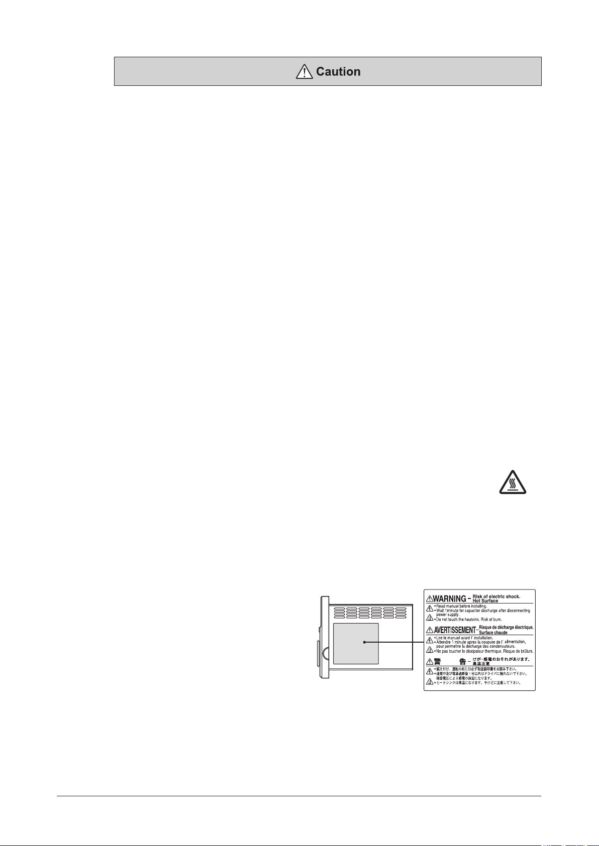
Warning information
A warning label with handling instructions is
attached on the driver. Be sure to observe the
instructions on the label when handling the driver.
Warning label
−4−
Driver side face

2 Precautions for use
This chapter covers limitations and requirements the user should consider when using the product.
Be sure to match the motor output power with the driver output power.
Connect protective devices to the power line
z
Connect a circuit breaker or earth leakage breaker to the driver’s power line to protect the primary circuit. If an
earth leakage breaker is to be installed, use one incorporating high-frequency noise elimination measures. Refer to
"Preventing leakage current" below for the selection of protective devices.
Do not perform vertical drive (gravitational operation)
z
The product will not be able to control the motor speed if an operation that the motor output shaft is externally rotated
is performed (vertical drive etc.). Also, if vertical drive is performed, since the inverter primary voltage of the circuit
may exceed the permissible range, the protective function may be activated. As a result, the motor may coast to a stop
and the load may fall.
Do not use a solid-state relay (SSR) to turn on/off the power
z
A circuit that turns on/off the power via a solid-state relay (SSR) may damage the motor and driver.
Do not conduct the insulation resistance measurement or dielectric strength test with the motor
z
and driver connected
Conducting the insulation resistance measurement or dielectric strength test with the motor and driver connected may
result in damage to the product.
Grease measures
z
On rare occasions, grease may ooze out from the gearhead. If there is concern over possible environmental damage
resulting from the leakage of grease, check for grease stains during regular inspections. Alternatively, install an
oil pan or other device to prevent leakage from causing further damage. Oil leakage may lead to problems in the
customer’s equipment or products.
Caution when using under low temperature environment
z
When an ambient temperature is low, since the load torque may increase by the oil seal or viscosity increment of
grease used in the gearhead, the output torque may decrease or an overload alarm may generate. However, as time
passes, the oil seal or grease is warmed up, and the motor can be driven without generating an overload alarm.
Preventing leakage current
z
Stray capacitance exists between the driver’s current-carrying line and other current-carrying lines, the earth and the
motor, respectively. A high-frequency current may leak out through such capacitance, having a detrimental effect on
the surrounding equipment. The actual leakage current depends on the driver’s switching frequency, the length of
wiring between the driver and motor, and so on. When connecting an earth leakage breaker, use one of the following
products offering resistance against high frequency current:
[ Mitsubishi Electric Corporation: NV series ]
Noise elimination measures
z
Provide noise elimination measures to prevent a motor or driver malfunction caused by external noise. For more
effective elimination of noise, use a shielded I/O signal cable or attach ferrite cores if a non-shielded cable is used.
Refer to p.40 for the noise elimination measures.
Connecting the motor and driver
z
Be sure to connect the connector type motor and the driver using the dedicated connection cable (sold separately).
The maximum distance between the motor and driver is 10.5 m (34.4 ft.), and the connection cables are provided up
to 10 m (32.8 ft.). Limit the number of times so that attaching/detaching between the connection cable and the motor
or driver will not exceed 100 times.
Connection cable
z
Do not apply a strong force on the locking lever of the connector for motor connection.
Applying a strong force on the locking lever may cause damage.
The driver uses semiconductor elements, so be extremely careful when handling them
z
Electrostatic discharge can damage the driver.
Be sure to ground the motor and driver to prevent them from being damaged by electric shock or static electricity.
Saving data to the non-volatile memory
z
The display blinks while pressing the setting dial to set the data or initializing the data (about 5 seconds). Do not turn
off the power supply while the display is blinking. Doing so may abort writing the data and cause an EEPROM error
alarm to generate. The non-volatile memory can be rewritten approximately 100,000 times.
Precautions for use
−5−

Preparation
BMUD 60 - C 2
Parallel shaft gearhead GFV gearhead
3 Preparation
3.1 Checking the product
Verify that the items listed below are included.
Report any missing or damaged items to the branch or sales ofce from which you purchased the product.
□
Driver ..............................................................1 unit
□
CN1 connector (3 pins) ................................1 pc
□
CN4 connector (9 pins) ................................1 pc
□
OPERATING MANUAL(this document) .....1 copy
□
QUICK START GUIDE ....................................1 copy
3.2 How to identify the product model
Driver
䐟 䐠 䐡 䐢
Driver type
①
Output power
②
Power supply voltage
③
Reference number
④
Motor
Round shaft
BLM 4 60 S H P - 5 A S
䐟 䐠 䐡 䐢 䐣 䐤 䐨 䐩 䐪
Right angle Hollow shaft Hypoid gear JH gearhead
BLM 4 60 S H P K - 4 H 10 S
䐟 䐠 䐡 䐣䐢 䐤 䐥 䐦 䐧 䐨
Motor type
①
Frame size
②
Output power
③
Motor classication
④
Motor connection method
⑤
Degree of protection for motorP: IP66 Blank: IP40
⑥
Combined motor
⑦
Frame size of combined motor4: 80 mm (3.15 in.) 5: 90 mm (3.54 in.)
⑧
Gearhead type
⑨
Gear ratio • Motor shaft type
⑩
Gearhead shaft type Blank: mm shaft type A: Inch shaft type
⑪
Material of output shaft
⑫
•A code is added to the end of the model name for the product that the motor connector position has been changed.
BMUD: BMU
30
: 30 W 60: 60 W
A
: Single-phase 100-120 V
C
: Single-phase, Three-phase 200-240 V
series driver
120
: 120 W
䐪
BLM
: Brushless Motor
2
: 60 mm (2.36 in.) 4: 80 mm (3.15 in.) 5: 90 mm (3.54 in.)
30
: 30 W 60: 60 W
S
H
: Connector type Blank: Cable type
K
: Round shaft type (with key)
H: JH
gearhead
Number: Gear ratio of gearhead
A
: Round shaft type
AC
: Round shaft type (Shaft at)
C, S
: Stainless steel A, B: Carbon steel
120
: 120 W
−6−
3.3 Products possible to combine
Protective lm
Mounting hole
eleration/deceleration
Protective lm
Products with which drivers can be combined are listed below.
Verify the driver model and the motor model against the model name described on the package label.
For details about the motor, refer to the operating manual supplied with the motor.
Preparation
Output power Power supply voltage Driver model Motor model
30 W
Single-phase 100-120 V
Single-phase, Three-phase 200-240 V
Single-phase 100-120 V
60 W
Single-phase, Three-phase 200-240 V
120 W
in the motor model name indicates a code or a number representing the gear ratio, the shaft shape, or the gearhead type.
o
*
Single-phase 100-120 V
Single-phase, Three-phase 200-240 V
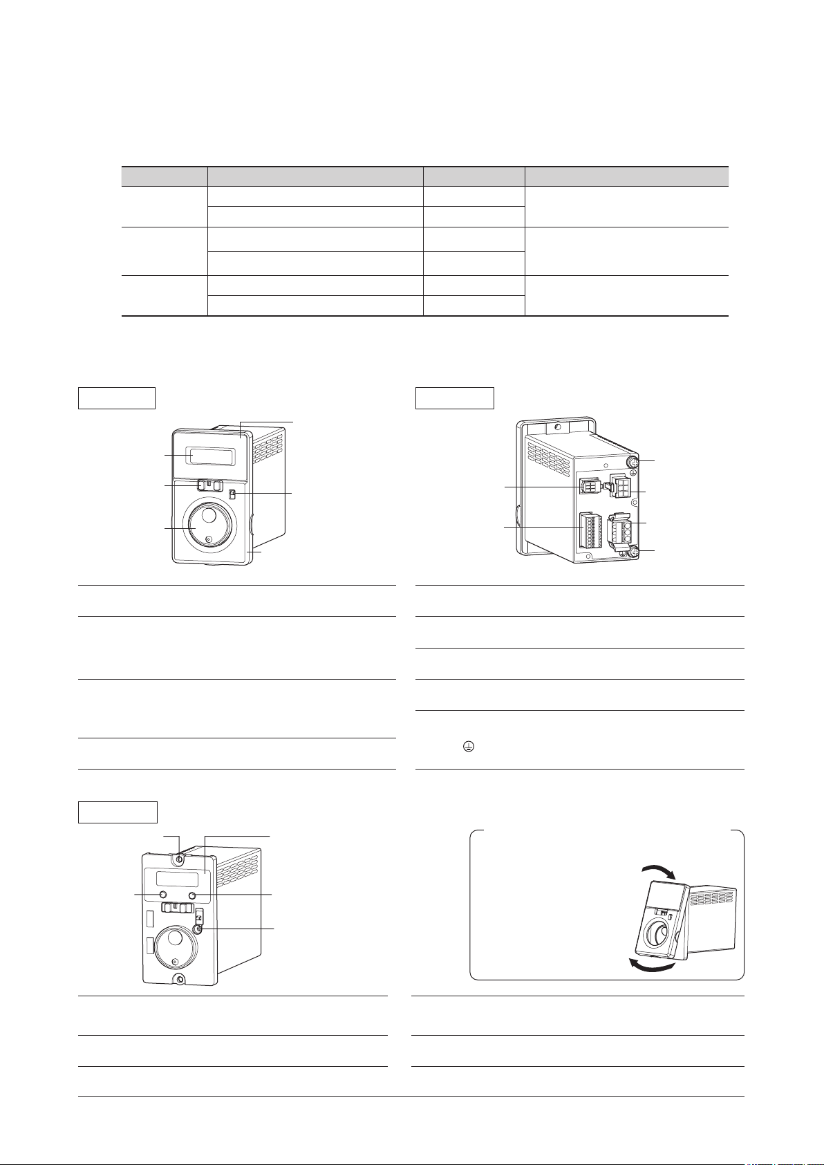
3.4 Names and functions of parts
Front side
Operation switch
Setting dial
When the front panel is attached
Display
Use after removing
the protective lm.
Rotation direction
switch
Front panel
BMUD30-A2
BMUD30-C2
BMUD60-A2
BMUD60-C2
BMUD120-A2
BMUD120-C2
Rear side
Sensor connector
(CN3)
I/O signals
connector
(CN4㻕
BLM230-
BLM260BLM460S-
oo
oo
oo
BLM460SHPK-
BLM5120-
oo
BLM5120HPK-
*
,
BLM230HP-
,
BLM260HP-
,
BLM460SHP-
oooo
,
BLM5120HP-
oooo
Protective
Earth Terminal
Motor connector
(CN2)
Main power supply
connector (CN1)
Protective
Earth Terminal
oo
oo
oo
oo
Display
Operation switch
Setting dial
Rotation direction
switch
Front side
(2 locations)
MODE key
This display shows the monitor item, alarms,
etc.
Setting the operation switch to the "RUN" side
causes the motor to start running.
Setting the operation switch to the "STAND-BY"
side causes the motor to stop.
This setting dial is used to change the rotation
speed or parameters.
After changing, the new value is determined
by pressing the setting dial.
This switch is used to change the motor
rotation direction.
When the front panel is removed
Use after removing
the protective lm.
FUNCTION key
Acc
time potentiometer
Sensor connector
(CN3)
I/O signals connector
(CN4)
Motor connector
(CN2)
Main power supply
connector (CN1)
Protective Earth
Terminal
Removing and installing the front panel
Installing
Install the front panel after
placing on the upper side of
the driver front face.
Removing
Remove the front panel
having the under side.
Connects the sensor connector (black) of the
motor cable or the connection cable.
Connects the I/O signals.
Connects the power connector (white) of the
motor cable or the connection cable.
Connects the main power supply.
Connects the ground terminal* of the
connection cable and the grounding wire.
Be sure to ground the driver using either of
the Protective Earth Terminals.
Connector type only
*
MODE key
FUNCTION key
This key is used to change the operation
mode.
This key is used to change the display of
the operation mode or the function.
Acceleration/deceleration
time potentiometer
Mounting hole
(2 locations)
This potentiometer is used to set the
acceleration/deceleration time.
Installs the driver with screws
(M4 or No.8-32UNC).
−7−
Installation
4 Installation
This chapter explains the installation location and installation methods of the driver.
4.1 Installation location
Install the driver in a well-ventilated place where they can be inspected easily and the following conditions are satised:
•Indoors
•Operating ambient temperature:
0 to +40 °C (+32 to +104 °F) (non-freezing)
•Operating ambient humidity:
85% or less (non-condensing)
•Area that is free of explosive atmosphere or toxic gas
(such as sulfuric gas) or liquid
•Area not exposed to direct sun
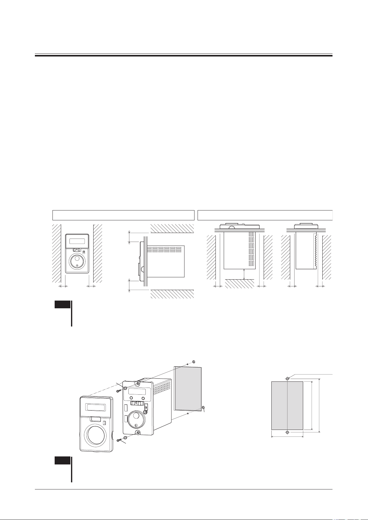
4.2 Installing the driver
Check on the Oriental Motor Website for the product dimension.
The driver is designed so that heat is dissipated via air convection and conduction through the enclosure.
There must be a clearance of at least 25 mm (0.98 in.) and 50 mm (1.97 in.) clearances in the horizontal and vertical
directions, respectively, between the driver and enclosure or other equipment within the enclosure.
Installation direction
When installing the driver, mount it turning the driver front panel to the front side or upper side.
•Area free of excessive amount of dust, iron particles or the like
•Area not subject to splashing water (rain, water droplets), oil
(oil droplets) or other liquids
•Area free of excessive salt
•Area not subject to continuous vibration or excessive shocks
•Area free of excessive electromagnetic noise (from welders,
power machinery, etc.)
•Area free of radioactive materials, magnetic elds or vacuum
•Altitude Up to 1000 m (3300 ft.) above sea level
When turning the driver front panel to the upper sideWhen turning the driver front panel to the front side
25 (0.98)
or more
25 (0.98)
or more
25 (0.98)
25 (0.98)
or more
25 (0.98)
or more
or more
25 (0.98)
or more
25 (0.98)
or more
Note •Do not install any equipment that generates a large amount of heat or noise near the driver.
•If the ambient temperature of the driver exceeds the upper limit of the operating ambient temperature, revise
the ventilation condition or forcibly cool the area around the driver using a fan in order to keep within the
operating ambient temperature.
Installation method
Install the driver to a at metal plate offering excellent vibration resistance.
Remove the front panel of the driver and secure the two mounting holes using pan head machine screws and nuts
(M4 or No.8-32UNC: not supplied). Tighten the screws until no gaps remain between the driver and mounting plate.
Removing and installing the front panel → p.7
Washer
Nut
• Plate cutout for mounting
25 (0.98)
or more
2×Ø4.5 (Ø0.177)
25 (0.98)
or more
)
+ 0.04
0
(3.19
+ 1
0
81
90±0.2 (3.54±0.008)
−8−
Pan head machine screw (M4 or No.8-32UNC: not supplied)
Tightening torque: 0.4 to 0.7 N·m (3.5 to 6.1 lb-in)
53
(2.09
0
)
0
[Unit: mm (in.)]
+ 1
+ 0.04
Note •The space between the mounting hole section and front panel of the driver is 4.5 mm (0.18 in.).
Therefore, the total height of the screw head and washer should be less than 4.5 mm (0.18 in.).
The front panel cannot be installed if it is exceeded 4.5 mm (0.18 in.).
•If the washer is used, use the washer which outer diameter is 8 mm (0.31 in.) or less.
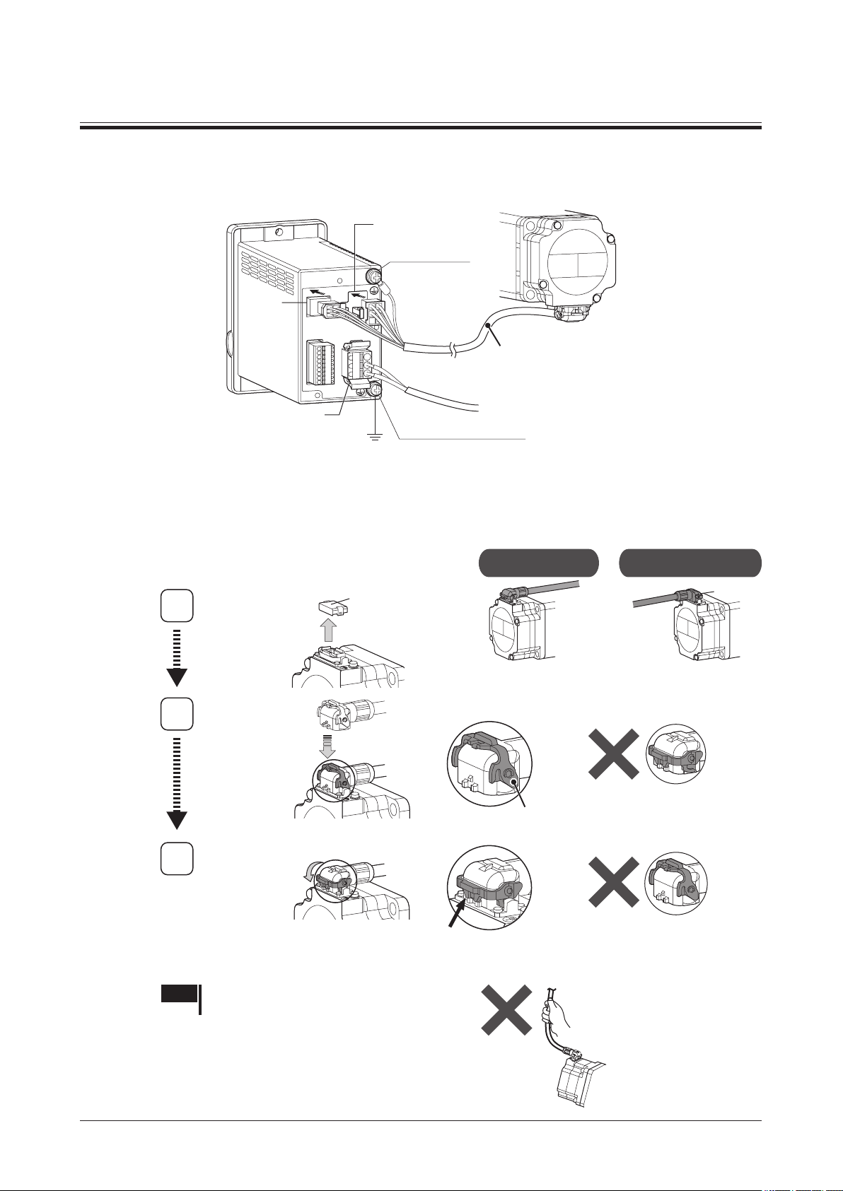
5 Connection
1
Connector cap
[ Cable leading direction ]
5.1 Connecting the motor and driver
There are the connector type motor and the cable type motor.
Connector type
CN2
Protective Earth
Terminal
CN3
Connection
Connection cable
(sold separately)
CN1
Grounding
Connect the motor connector (white) of the connection cable to the CN2, and the sensor connector (black) to the CN3
on the driver.
Connection procedures of the motor and connection cable
z
Connect the dedicated connection cable (sold separately)
to the motor and driver.
The connection cables are provided up to 10 m (32.8 ft.).
Protective Earth Terminal
Be sure to ground.
To power supply⇒ p.12
Leading in direction
of output shaft
Leading in opposite
direction of output shaft
Remove
Attach
2
Position of lever
Locking lever
The connector cannot be
inserted if the locking lever is
turned down.
Secure
3
Be sure to turn down
the locking lever till the
position shown in the gure.
Note Do not carry the motor by holding the cable.
Doing so may cause damage to the product.
The connector cannot be
secured unless the locking
lever is turned down.
−9−
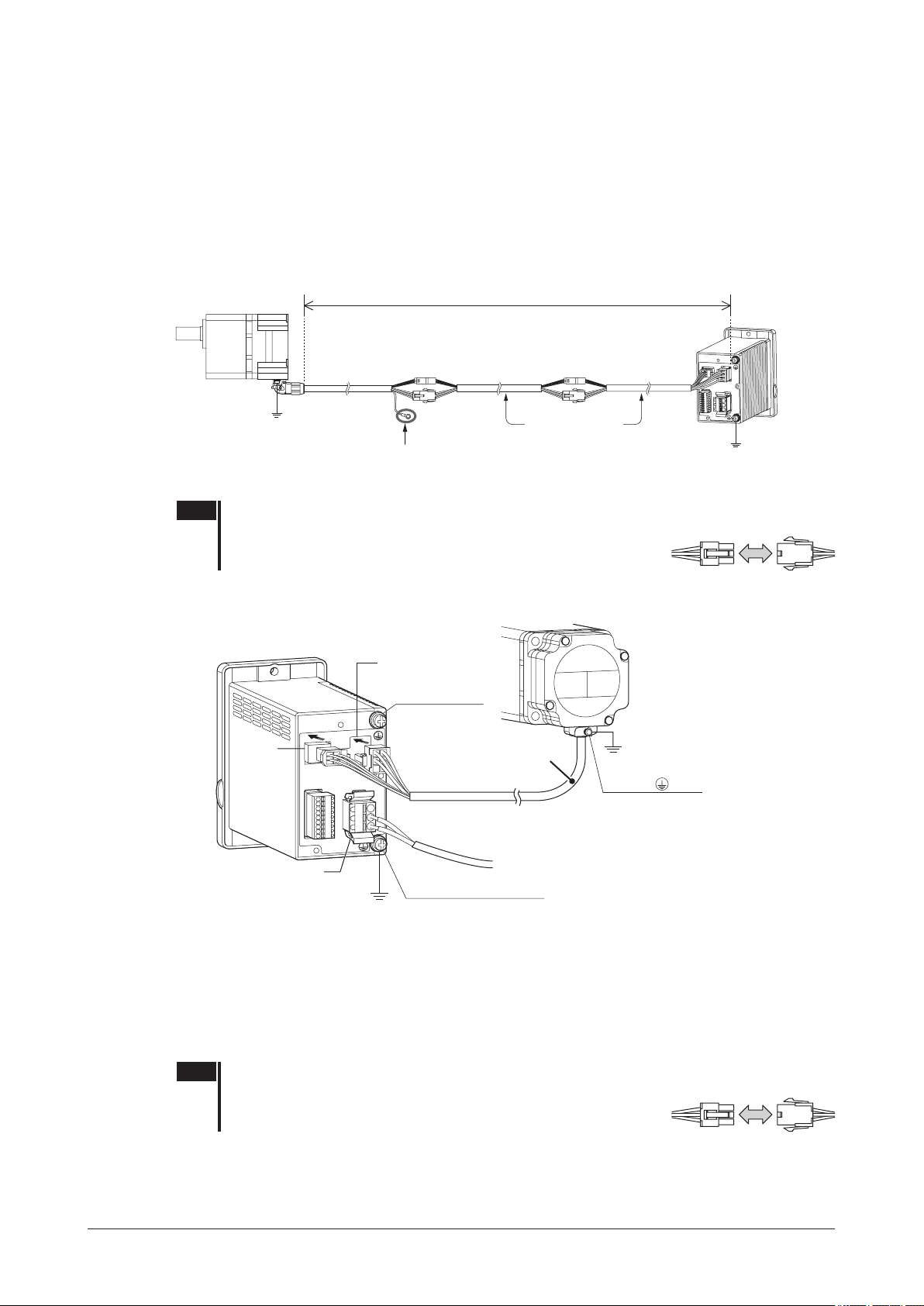
Connection
10.5 m (34.4 ft.)
Detaching the connection cable
z
If the locking lever is turned up, the cable can be detached.
Extension between motor and driver
z
Use a connection cable (accessory) for relay when extending the wiring distance between the motor and driver.
The connection cable for relay can be used by connecting up to 2 pieces. The wiring distance between the motor and
driver can be extended to a maximum of 10.5 m (34.4 ft.).
Refer to p.38 for the connection cable for relay.
Example of use: Example of extension by adding two connection cables [10.5 m (34.4 ft.)]
0.5 m (1.6 ft.) 7 m (23.0 ft.)
Connection cable
Grounding
Be sure to ground.
Note
•Secure each connectors part not to apply stress on the connectors part. If not secured, the
CC005HBLB
Be sure to insulate the
terminal not in use.
Flexible connection cable
CC07BL2R
Connecting for relay
3 m (9.8 ft.)
Connection cable
CC03BL2
Grounding
Be sure to ground.
cables may damage by the stress.
•Securely insert the connector straight. Insecure connections may
cause malfunction or damage to the motor or driver.
Cable type
CN2
Protective Earth
Terminal
CN3
Motor cable
[0.5 m (1.6 ft.)]
Grounding
Protective Earth
Terminal
Be sure to ground.
−10−
CN1
Grounding
Protective Earth Terminal
Be sure to ground.
To power supply⇒ p.12
Connect the motor connector (white) of the motor cable to the CN2, and the sensor connector (black) to the CN3 on
the driver.
Use a connection cable (accessory) for relay when extending the wiring distance between the motor and driver.
The connection cable for relay can be used by connecting up to 2 pieces. The wiring distance between the motor and
the driver can be extended up to 10.5 m [34.4 ft.] (including the motor cable).
Refer to p.38 for the connection cable for relay.
Note
•Secure each connectors part not to apply stress on the connectors part. If not secured, the
cables may damage by the stress.
•Securely insert the connector straight. Insecure connections may
cause malfunction or damage to the motor or driver.
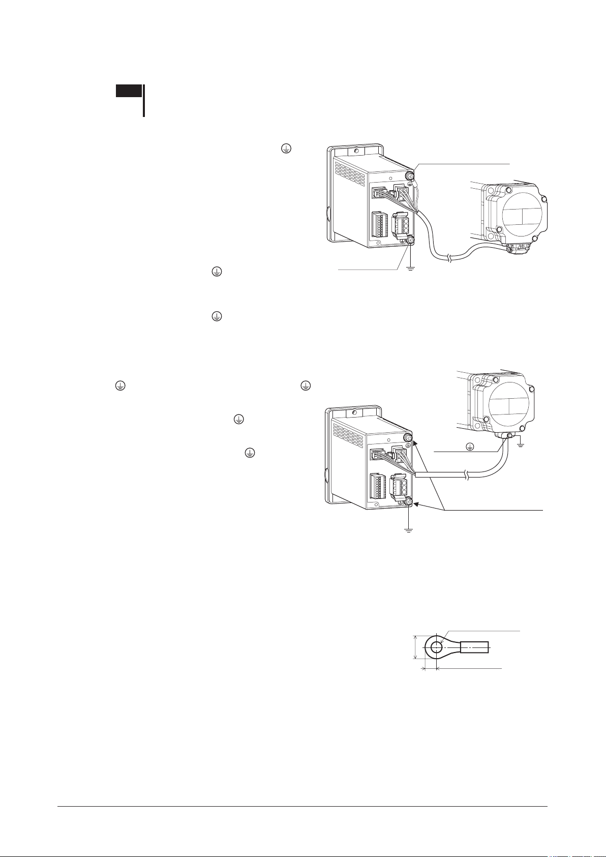
5.2 Grounding
[Unit: mm (in.)]
Note Be sure to ground the motor and driver. Failure to do so may result in electric shock or damage to
the product. Static electricity may cause damage to the product if the Protective Earth Terminals
are not grounded.
Connector type
Ground using the Protective Earth Terminals of
the motor and driver, as well as the ground terminal
of the connection cable.
Connect the ground terminal of the connection cable
to the driver as shown in the gure.
However, the grounding resistance value provided
in the standards that is applied to the equipment may
not be satised depending on the type or length of
the connection cable.
In this case, ground near the motor using the
Protective Earth Terminal
If the ground terminal of the connection cable is not
used, be sure to insulate.
For the driver, ground near the driver using the
Protective Earth Terminal
Do not share the Protective Earth Terminal with a
welder or any other power equipment.
on the motor.
.
Protective Earth Terminal
Protective Earth
Terminal
Be sure to ground.
Reference
Protective earth wire of the connection cable
Conductor size: AWG18 (0.75 mm
Maximum conductor resistance: 25.0 Ω/km
Grounding
2
)
Connection
Cable type
Be sure to ground using the Protective Earth Terminal
of the motor and the Protective Earth Terminal
of the driver.
Two Protective Earth Terminals
the driver. Ground either of the two Protective Earth
Terminals near the driver. You can ground either of
the two Protective Earth Terminals
that is not grounded is used as a service terminal. Use
the service terminal according to your specic need,
such as connecting it to the motor in order to ground
the motor. Do not share the Protective Earth Terminal
with a welder or any other power equipment.
Connecting to Protective Earth Terminal
To connect to the Protective Earth Terminal, ground using the following grounding terminal. Ground as a short
distance as possible.
are provided on
. The terminal
Grounding
Protective Earth
Terminal
Be sure to ground.
Protective Earth Terminal
Be sure to ground either of
the Protective Earth Terminals.
Ground terminal
•Applicable crimp terminal: Round crimp terminal with insulation cover
•Thread size of terminal: M4
•Tightening torque: 1.2 N·m (10.6 lb-in)
•Applicable lead wire: AWG18 to 14 (0.75 to 2.0 mm
2
)
Ø4.1 (0.16) or more
Grounding
4.8 (0.19) or less
Precautions about static electricity
Static electricity may cause the driver to malfunction or suffer damaged.
Be sure to ground the motor and driver to prevent them from being damaged by static electricity.
−11−
Connection
• Single-phase 100-120 V • Single-phase 200-240 V • Three-phase 200-240 V
Screwdriver
10 mm
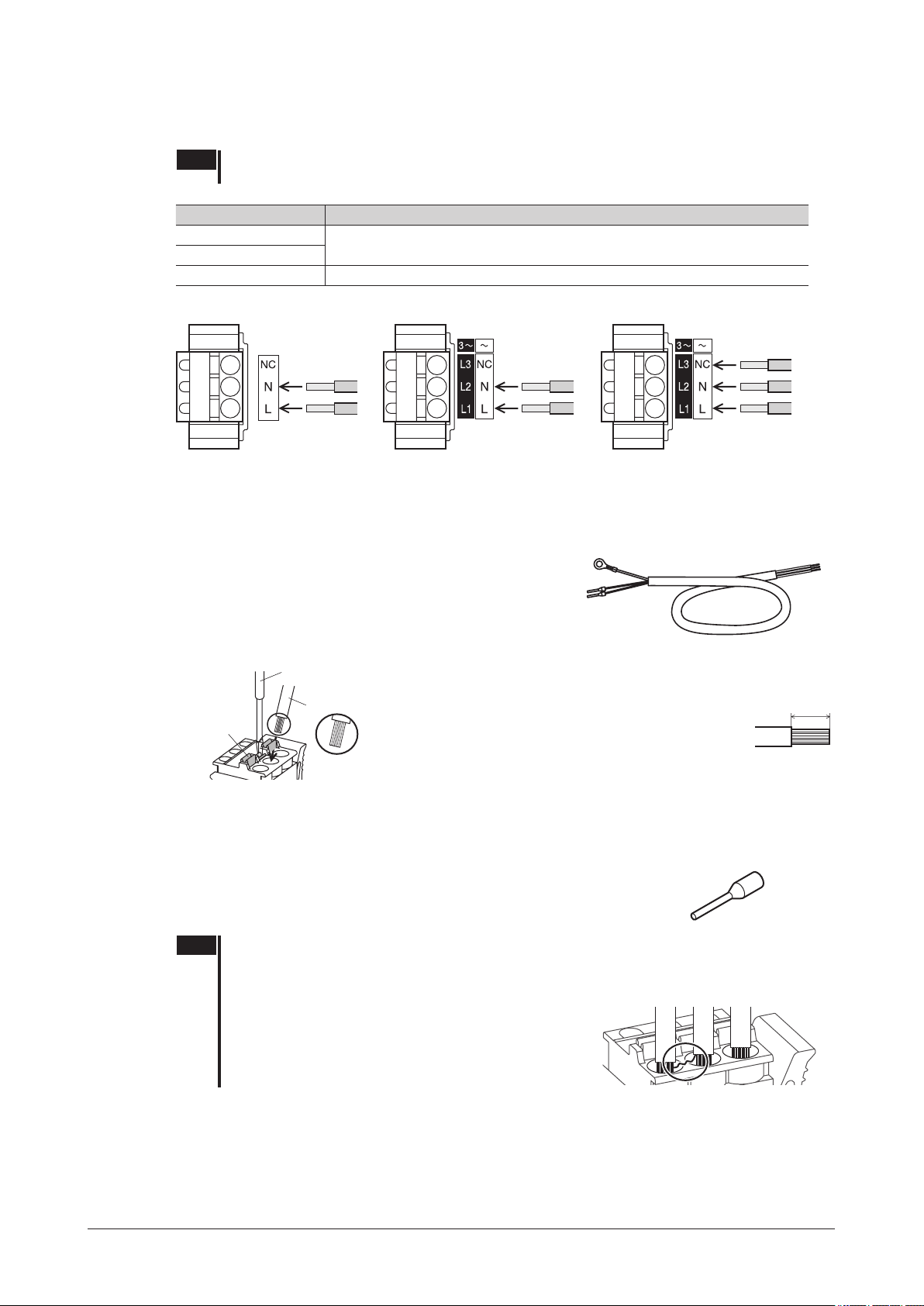
5.3 Connecting the power supply
Connect the power supply cable to the CN1 on the driver.
Note Check the specication of the power supply voltage for the driver before applying a voltage.
If a voltage exceeding the rated range is applied, the driver may be damaged.
Input power supply Connecting method
Single-phase 100-120 V
Single-phase 200-240 V
Three-phase 200-240 V Connect the R, S and T phase lines to the L1, L2 and L3 terminals, respectively.
Connector model: FKC2,5/3-ST-5,08-RF (PHOENIX CONTACT GmbH & Co. KG)
The same driver can be used for single-phase 200-240 V and three-phase 200-240 V.
Connecting terminals vary depending on the power supply voltage used.
Connect the live side to terminal L, and the neutral side to terminal N.
Connecting method
The power supply cable is not included.
Power supply cables crimped terminals in advance are provided as
accessories (sold separately).
Insert the lead wire while pushing the button of the orange color with a screwdriver.
•Lead wire size: AWG18 to 14 (0.75 to 2.0 mm2)
•Length of the insulation cover which can be peeled:
10 mm (0.39 in.)
•Conductive material: Use only copper wire.
(0.39 in.)
Button of the
orange color
Lead wire
Wire the lead wire so that
the tip part (copper wires)
does not become loose.
Crimp terminals can also be used to connect.
If crimp terminals are used, select the following terminals.
Manufacturer: PHOENIX CONTACT GmbH & Co. KG
Model: AI 0,75-10 [ Conductor cross-sectional area: 0.65 to 0.82 mm
AI 1-10 [ Conductor cross-sectional area: 0.82 to 1.2 mm
AI 1,5-10 [ Conductor cross-sectional area: 1.25 to 1.8 mm
AI 2,5-10 [ Conductor cross-sectional area: 2.0 to 3.0 mm
2
(AWG18) ]
2
(AWG18) ]
2
(AWG16) ]
2
(AWG14) ]
Note •When cycling the power or plugging/unplugging the connector, turn off the power and wait for 1 minute
or more before doing so.
•Ensure that the connector plugged in securely. Insecure connections may cause malfunction or
damage to the product.
•Insert the lead wire to the connector so that the tip part
(copper wires after stripping the insulation cover) does
not become loose. The loose tip part (copper wires)
may cause short-circuiting, leading to damage to the
product.
Circuit breaker
Be sure to connect a circuit breaker to the power line of the driver to protect the primary circuit.
−12−
Rated current of protective device: Single-phase input 10 A, three-phase input 5 A
Circuit breaker: Mitsubishi Electric Corporation NF30
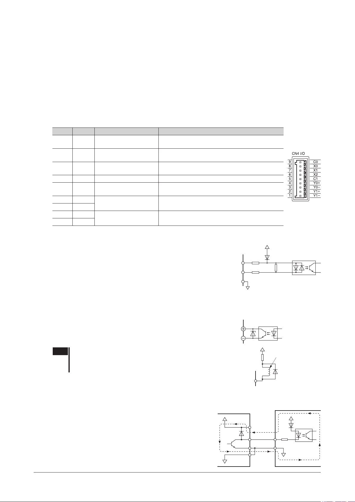
5.4 Connecting the I/O signals
+5 V
Pin No.
External control
Connect the I/O signals to CN4 on the driver. Refer to p.16 for connection examples with a programmable controller.
Connecting the lead wire
•Applicable lead wire: AWG26 to 20 (0.14 to 0.5 mm2)
•Length of the insulation cover which can be peeled: 8 mm (0.31 in.)
Crimp terminals can also be used to connect. If crimp terminals are used, select the following terminals.
Manufacturer: PHOENIX CONTACT GmbH & Co. KG
Model: A 0,25-7 [ Conductor cross-sectional area: 0.14 to 0.34 mm
A 0,34-7 [ Conductor cross-sectional area: 0.14 to 0.34 mm
A 0,5-8 [ Conductor cross-sectional area: 0.40 to 0.65 mm
Connector model: FK-MC0,5/9-ST-2,5 (PHOENIX CONTACT GmbH & Co. KG)
CN4 pin assignment
Pin No. Terminal Function
9 C0
8 X0 [FWD]
7 X1 [REV]
6 X2 [M0] This signal is used to select the operation data.
5 C1
4 Y0+
3 Y0−
2 Y1+
1 Y1−
The signal in brackets [ ] is a function that is assigned at the time of shipment. The assigned functions can be changed by setting
*
parameters. Refer to p.27 for details.
Input signal common
(For external power supply)
(For internal power supply)
[SPEED-OUT]
[ALARM-OUT1]
*
0 V
2
(AWG24) ]
2
(AWG22) ]
2
(AWG20) ]
Description
Connect when using the external power supply.
The motor rotates in the forward direction while this
signal is being "ON."
The motor rotates in the reverse direction while this
signal is being "ON."
Connect when using the built-in power supply.
30 pulses are output with each revolution of the motor
output shaft.
This signal turns OFF when an alarm generates
(normally closed).
Connection
Input signal circuit
All input signals of the driver are photocoupler inputs. Use these signals by the
internal power supply (+5 VDC) or external power supply.
When using the external power supply, both sink input logic and source input
logic can be used by changing the wiring.
Usable external power supply: 24 VDC −15% to +20%, 100 mA or more
Output signal circuit
Pin No.
9
6䡚8
5
The driver outputs signals are photocoupler/open-collector output.
When driving each element using the output signal circuit, give consideration to this ON voltage.
ON voltage: 1.5 VDC maximum
External power supply: 4.5 to 30 VDC, 100 mA or less
(5 mA or more for the SPEED-OUT output)
2䚸4
1䚸3
Note When connecting a relay (inductive load), etc., to detect alarm
outputs, use a relay with built-in ywheel diode, or provide a
y-back voltage control measure based on diode, etc., for the
inductive load.
CN4
Pin No.2, 4
Using a external control equipment with a built-in clamp diode
If a external control equipment with a built-in clamp diode is used, a
leakage path may form and cause the motor to operate even when the
external control equipment power is off, as long as the driver power is
equipment
VCC
on. Since the power capacity of the controller is different from that of
the driver, the motor may operate when the external control equipment
and driver powers are turned on or off simultaneously.
When powering down, turn off the driver power rst, followed by the
external control equipment power. When powering up, turn on the
external control equipment power rst, followed by the driver power.
0 V
5 kΩ
680 Ω
0 V
820 Ω
Photocoupler
Inductive load
Flywheel
diode
Driver
+5 V
CN4
6 to 8
5
0 V
−13−
Connection
Driver
Driver
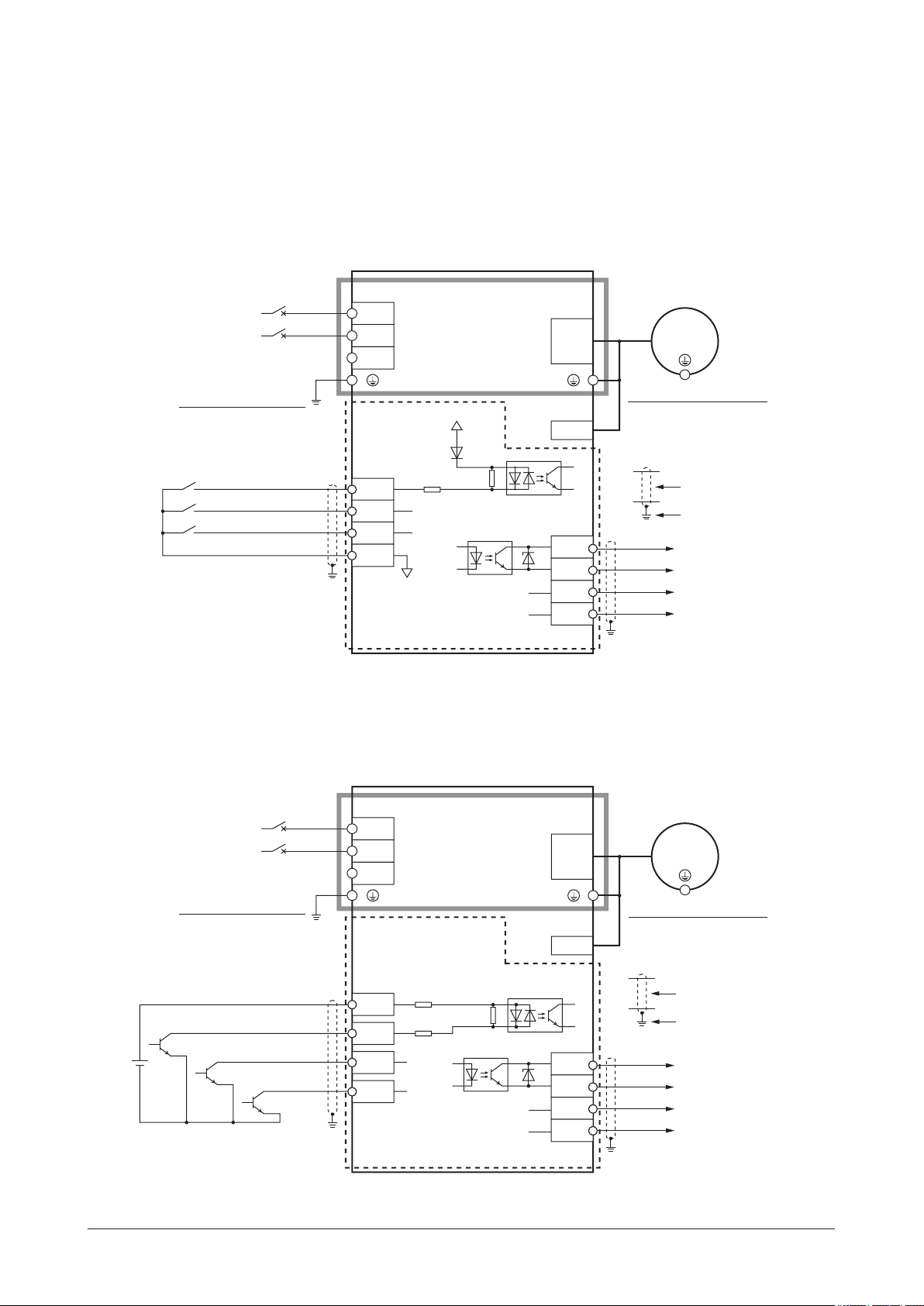
5.5 Connection diagram
The connection example is of the single-phase input. The power supply connection for the three-phase input is different.
(5.3 Connecting the power supply ⇒ p.12)
Sink logic
When using the built-in power supply
z
This is a connection example for when the built-in power supply is used for input signals.
The I/O signal in the brackets [ ] is the assignment at the time of shipment.
CN1
L
N
NC
Power supply
connection
Circuit breaker
L
N
Grounding the driver
Be sure to ground.
X0䠷FWD䠹
X1䠷REV䠹
X2䠷M0䠹
C1䠄0 V䠅
Be sure to ground. Refer to "5.2 Grounding" on p.11 for grounding.
*
When using the external power supply
z
Control circuit
CN4
8
7
6
5
Main circuit
820 Ω
680 Ω
0 V
Motor connector
+5 V
CN2
Sensor
connector
CN3
Motor connection
4
3
2
1
Y0+
Y0−
Y1+
Y1−
This is a connection example for when the external power supply is used for input signals.
The I/O signal in the brackets [ ] is the assignment at the time of shipment.
Motor
Grounding the motor ∗
Be sure to ground.
Shielded cable
Grounding
䠷SPEED-OUT䠹
䠷ALARM-OUT1䠹
Refer to the p.16 for
connection of output signals.
−14−
Power supply
connection
Grounding the driver
Circuit breaker
L
N
CN1
L
N
NC
Main circuit
Be sure to ground.
Control circuit
Connecting input signals
20.4䡚28.8 VDC
100 mA or more
Be sure to ground. Refer to "5.2 Grounding" on p.11 for grounding.
*
C0
X0䠷FWD䠹
X1䠷REV䠹
X2䠷M0䠹
CN4
9
8
7
6
5 kΩ
680 Ω
820 Ω
Motor coannector
CN2
Sensor
connector
CN3
4
3
2
1
Motor conanection
Motor
Grounding the motor ∗
Be sure to ground.
Shielded cable
Grounding
Y0+
Y0−
Y1+
Y1−
䠷SPEED-OUT䠹
䠷ALARM-OUT1䠹
Refer to the p.16 for
connection of output signals.
 Loading...