

Page 1

HM-5109-7
Brushless Motor and Driver Package
BLE Series
Standard type, Electromagnetic brake type
OPERATING MANUAL
Thank you for purchasing an Oriental Motor product.
This Operating Manual describes product handling procedures and safety precautions.
•Please read it thoroughly to ensure safe operation.
•Always keep the manual where it is readily available.
Table of contents
1 Introduction ..........................................2
2 Safety precautions ...............................4
3 Precautions for use ..............................6
4 System conguration ...........................7
5 Preparation ..........................................8
5.1 Checking the product .............................. 8
5.2 How to identify the product model ........... 8
5.3 Combination tables ................................. 9
5.4 Names and functions of parts ............... 10
6 Installation..........................................12
6.1 Installation location ................................ 12
6.2 Installation overview .............................. 12
6.3 Installing the combination parallel shaft
gearhead ............................................... 13
6.4 Installing the round shaft type ............... 14
6.5 Installing the combination type
hollow shaft at gearhead ..................... 14
6.6 Installing a load ..................................... 17
6.7 Permissible radial load and
permissible axial load ............................ 19
6.8 Installing the driver ................................ 20
6.9 Installing the regeneration unit
(accessory) ............................................ 22
6.10 Installing the external potentiometer
(supplied) .............................................. 22
6.11 Installing and wiring in compliance with
EMC Directive ....................................... 23
7 Connection.........................................25
7.1 Connection example ............................. 25
7.2 Connecting the power supply ................ 26
7.3 Grounding ............................................. 26
7.4 Connecting the motor and driver ........... 27
7.5 Connecting the regeneration unit .......... 28
7.6 Selecting the I/O signal power supply ... 29
7.7 Connecting the I/O signals .................... 29
7.8 Connecting the communication cable ... 34
7.9 Connection diagram (example) ............. 35
8 Operation ...........................................38
8.1 Operation overview ............................... 38
8.2 Basic operation ..................................... 39
8.3 Setting the acceleration time and
deceleration time ................................... 41
8.4 Changing the speed .............................. 42
8.5 Examples of operation patterns ............ 42
8.6 Parallel operation .................................. 43
Ⅱ
8.7 Setting the
operation ............................................... 44
FBL
compatible mode and
9 Extended functions ............................47
10 Inspection ..........................................47
11 Protection function .............................48
12 Troubleshooting and remedial
actions ...............................................50
13 Accessories (sold separately) ............51
Page 2

Introduction
1 Introduction
Before use
Only qualied personnel should work with the product. Use the product correctly after thoroughly reading the section
“2 Safety precautions” on p.4. In addition, be sure to observe the contents described in warning, caution, and note in
this manual.
The product described in this manual has been designed and manufactured to be incorporated in general industrial
equipment. Do not use it for any other purpose. Oriental Motor will not be liable for whatever damage arises from
failure to observe this warning.
Product overview
The
box-type driver.
Each unit has a
same settings.
With the accessory data setter
performance and set operation data/ parameters and motor operations with ease.
Standards and CE Marking
This product is recognized by UL. The CE Marking (Low Voltage Directive and EMC Directive) is afxed to the
product in accordance with EN Standards.
The name of products certied to conform with relevant standards are represented by applicable unit model motor and
driver part numbers.
Series is a line of units, each consisting of a compact, high-torque brushless motor and a high-functional
BLE
compatible mode, so existing users of
FBL
Ⅱ
OPX-2A
Series units can use the
FBL
Ⅱ
(sold separately) or support software
MEXE02
Series units with the
BLE
, you can improve the
Applicable Standards
z
Applicable Standards Certication Body Standards File No. CE Marking
UL 1004-1
CSA C22.2 No.100
Motor
Driver
Thermal class UL/CSA Standards: 105(A), EN Standards: 120(E)
*
A temperature test has been conducted with a radiation plate. The size, thickness and material of the radiation plates
are as below table.
Model Size [mm (in.)] Thickness [mm (in.)] Material
BLEM23
BLEM46
BLEM512
Electromagnetic brake type: 135×135 mm (5.31×5.31 in.)
*
Installation conditions
z
Motor is to be used as a component within other
equipment
Overvoltage category:
Pollution degree: 3
Protection against electric shock: ClassⅠequipment
Overvoltage category II when EN 60950-1 is applicable.
*
Low Voltage Directive
z
The product is a type to be incorporated into machinery, so it should be installed within an enclosure.
•Install the product within the enclosure in order to avoid contact with hands.
•Be sure to maintain a Protective Earth in case hands should make contact with the product. Securely ground the
Protective Earth Terminals of the motor and driver.
EN 60034-1
*
EN 60034-5
EN 60664-1
EN 60950-1
UL 508C
CSA C22.2 No.274
EN 60950-1
EN 61800-5-1
115×115 (4.53×4.53)
135×135 (5.31×5.31)
165×165 (6.50×6.50)
*
Motor Driver
Ⅲ
*
UL E335369
Conform to EN Standards
UL E171462
Conform to EN Standards
5 (0.20) Aluminum
Motor is to be used as a component within other
equipment
Overvoltage category:
Pollution degree: 2
Protection against electric shock: ClassⅠequipment
Low Voltage Directive
EMC Directive
Ⅲ
*
−2−
Page 3

Introduction
EMC Directive
z
This product bears the CE mark under the conditions specied in “Example of motor and driver installation and
wiring” on p.24. Be sure to conduct EMC measures with the product assembled in your equipment by referring to “6.11
Installing and wiring in compliance with EMC Directive” on p.23.
Applicable Standards
Emission Tests
EMI
EMS Immunity Tests EN 61000-6-2, EN 61800-3 C3
Caution: This equipment is not intended for use in residential environments nor for use on a lowvoltage public
UL RECOGNITION OF DRIVER
Drivers are recognized by UL at following condition.
•Maximum Surrounding Air Temperature 50°C.
•Install device in pollution degree 2 environment.
•Solid state motor overload protection reacts at less than 160% FLA.
•Suitable For Use On A Circuit Capable Of Delivering Not More Than 5,000 Arms Symmetrical Amperes, 120 or
240 VAC Maximum Voltage.
•Integral solid state short circuit protection does not provide branch circuit protection. Branch circuit protection
must be provided in accordance with the National Electric Code and any additional local codes.
•Use UL Listed Inverse Time Circuit Breaker rated 120 or 240 VAC, 15 A Only.
•Drives have no provision for motor over temperature protection. Motor over temperature protection is required at
end application.
Harmonics Current Test
Voltage Fluctuations Test
network supplied in residential premises, and it may not provide adequate protection to radio reception
interference in such environments.
EN 55011 group 1 class A
EN 61000-6-4, EN 61800-3 C3
EN 61000-3-2
EN 61000-3-3
RoHS Directive
The products do not contain the substances exceeding the restriction values of RoHS Directive (2011/65/EU).
−3−
Page 4
Safety precautions
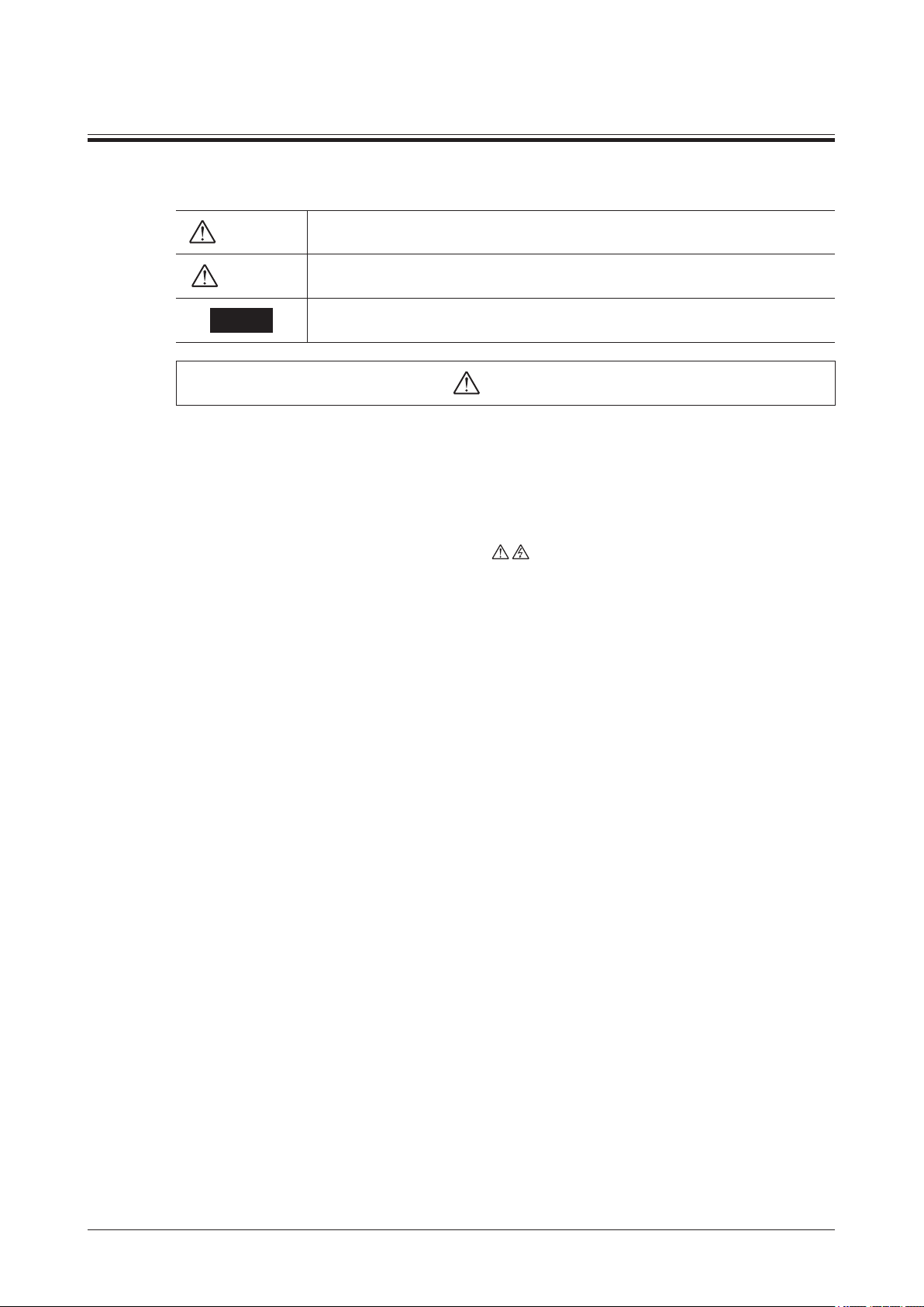
Warning
Caution
Note
Warning
2 Safety precautions
The precautions described below are intended to prevent danger or injury to the user and other personnel through
safe, correct use of the product. Please read and understand these precautions thoroughly before using the product.
Handling the product without observing the instructions that accompany a “Warning”
symbol may result in death or serious bodily injury.
Handling the product without observing the instructions that accompany a “Caution”
symbol may result in bodily injury or property damage.
The items under this heading contain important handling instructions that the user
should observe to ensure the safe use of the product.
•Do not use the product in a place exposed to explosive, ammable or corrosive gases or water splashes or near
combustible materials. Doing so may result in re, electric shock or injury.
•Only qualied personnel should be allowed to perform installation, connection, operation and inspection/
troubleshooting of the product. Handling by unqualied personnel may result in re, electric shock, injury or
equipment damage.
•Do not move, install, connect or inspect the product while the power is supplied. Perform these operations after
turning off the power. Failure to observe these instructions may result in electric shock.
•The terminals on the driver’s front panel marked with
touch these terminals while the power is on to avoid the risk of re or electric shock.
•Do not use a non-electromagnetic brake type motor in a vertical application. If the driver’s protection function is
activated, the motor will stop and the moving part of the equipment will drop, thereby causing injury or equipment
damage.
•Do not use the brake mechanism of the electromagnetic brake motor as a safety brake. It is intended to hold the
moving parts and motor position. Doing so may result in injury or damage to equipment.
•If the driver’s protection function has been activated, remove the cause and then reset the protection function.
Continuing to operate the equipment without removing the cause of problem will lead to a motor or driver
malfunction, resulting in injury or equipment damage.
•Use a specied motor (gearhead) and driver combination. Failure to do so may result in re, electric shock or
equipment damage.
•Use the motor and driver only in class I equipment. Installing them in equipment of other classes may result in
electric shock.
•Install the motor and driver in an enclosure. Failure to do so may result in electric shock or injury.
•When installing the motor and driver, connect their Protective Earth Terminals. Failure to do so may result in
electric shock.
•Securely connect the cables in accordance with the connection examples. Failure to do so may result in re or
electric shock.
•Do not forcibly bend, pull or pinch the cables. Doing so may result in re or electric shock.
•Do not machine or modify the motor cable or connection cable. Doing so may result in electric shock or re.
•Be sure to observe the specied cable sizes. Use of unspecied cable sizes may result in re.
•Observe the specied screw tightening torque when connecting terminals to the terminal block. Failure to do so
may result in electric shock or equipment damage.
•Always keep the driver’s power supply voltage below the rating. Failure to do so may result in re or electric
shock.
•When using the electromagnetic brake motor, do not turn the MB-FREE input ON while a load is held in vertical
direction. Otherwise, the holding power of the motor and electromagnetic brake will be lost, causing personal
injury or damage to equipment.
•When using the electromagnetic brake motor in vertical drive (gravitational operation), be sure to operate after
checking the load condition. If a load in excess of the rated torque is applied or the small torque limiting value is
set using a
•Always turn off the power before performing maintenance/inspection. Failure to do so may result in electric shock.
•Do not touch the motor or driver when measuring insulation resistance or performing a dielectric strength test.
Accidental contact may result in electric shock.
•Do not touch the connection terminals on the driver immediately (within 30 seconds or until the CHARGE LED
turns off) after the power is turned off. Residual voltage may cause electric shock.
•Regularly check the openings in the driver for accumulated dust. Accumulated dust may cause re.
OPX-2A
or
MEXE02
, the load may fall. This may result in injury or damage to equipment.
symbol indicate the presence of high voltage. Do not
−4−
Page 5
Safety precautions
Caution
•Do not disassemble or modify the motor (gearhead) and driver. Doing so may result in electric shock, injury or
equipment damage. Should you require inspection or repair of internal parts, please contact the Oriental Motor
branch or sales ofce from which you purchased the product.
•Do not use the product in conditions exceeding the motor (gearhead) or driver specications. Doing so may result
in electric shock, re, injury or equipment damage.
•Do not insert an object into the openings in the driver. Doing so may result in re, electric shock or injury.
•Do not touch the motor (gearhead) or driver during the operation or immediately after the operation has stopped.
Touching a hot motor (gearhead) or driver surface may cause a skin burn(s).
•Do not carry the product by the motor (gearhead) output shaft or any of the cables. Doing so may result in injury.
•Do not place around the motor and driver any object blocking the air ow. Doing so may result in equipment
damage.
•Do not touch the motor output shaft (key groove or pinion) with bare hands. Doing so may result in injury.
•When assembling the motor (pinion shaft) with the gearhead, exercise caution not to pinch your ngers or other
parts of your body between the motor and gearhead. Injury may result.
•Securely afx the motor (gearhead) and driver to their respective mounting plates. Inappropriate installation may
cause the motor/driver to detach and fall, resulting in equipment damage.
•Provide a cover on the rotating part (output shaft) of the motor (gearhead). Failure to do so may result in injury.
•When installing the motor (gearhead) in the equipment, exercise caution not to pinch your ngers or other parts of
your body between the equipment and motor or gearhead. Injury may result.
•Securely install the load on the motor output shaft. Inappropriate installation may result in injury.
•For the I/O signals power supply, use a DC power supply with reinforced insulation on its primary and secondary
sides. Failure to do so may result in electric shock.
•Provide an emergency stop device or emergency stop circuit external to the equipment so that the entire equipment
will operate safely in the event of a system failure or malfunction. Failure to do so may result in injury.
•Immediately when trouble has occurred, stop running and turn off the driver power. Failure to do so may result in
re, electric shock or injury.
•Do not touch the rotating part (output shaft) during operation. Doing so may result in injury.
•The motor surface temperature may exceed 70 °C (158 °F) even under normal operating
conditions. If the operator is allowed to approach a running motor, attach a warning label as
shown to the right in a conspicuous position. Failure to do so may result in skin burn(s).
•Use an insulated screwdriver to adjust the internal speed potentiometer, acceleration time potentiometer,
deceleration time potentiometer and switches in the driver. Failure to do so may result in electric shock.
•Dispose the product correctly in accordance with laws and regulations, or instructions of local governments.
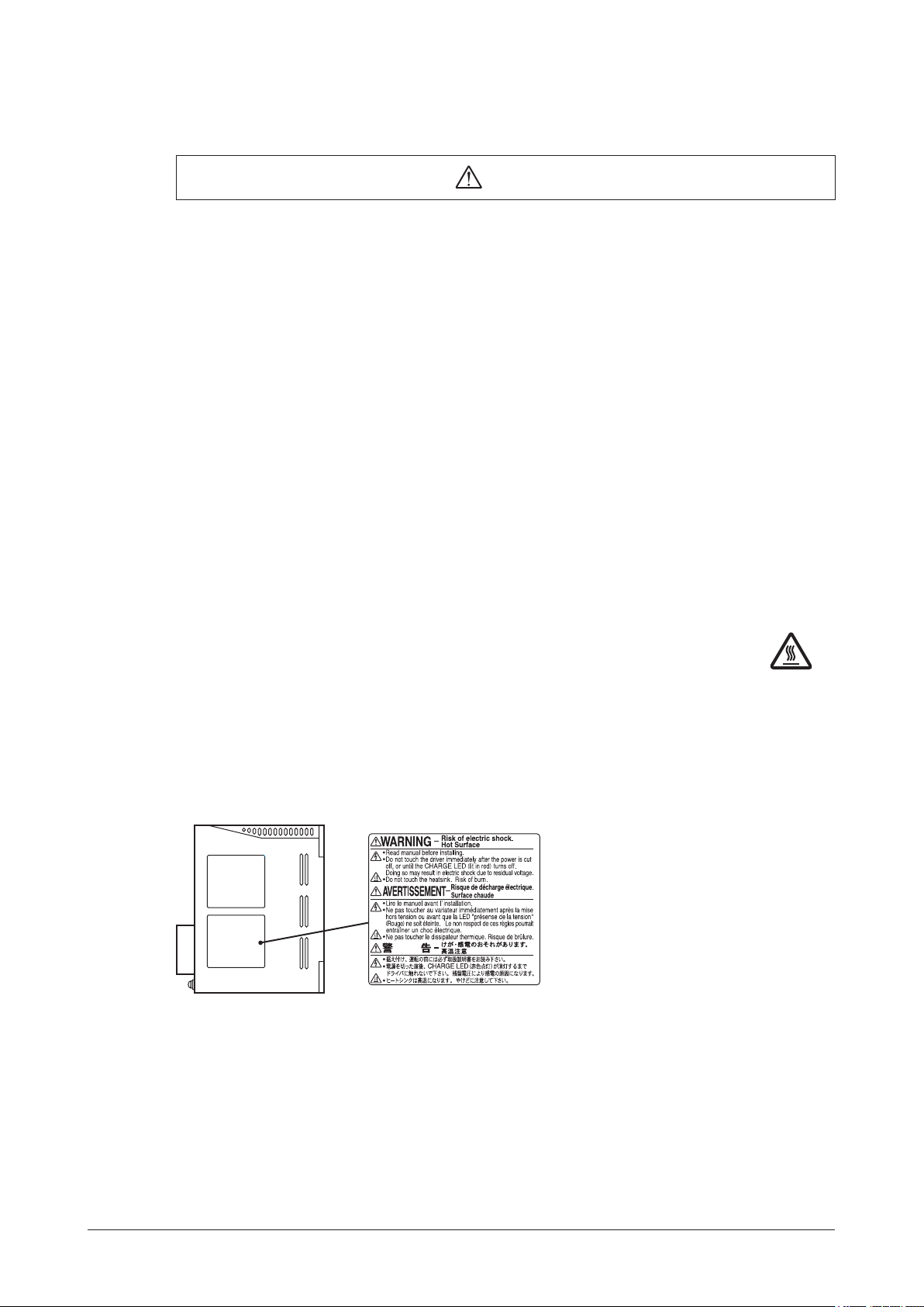
Warning label
Warning information
A warning label with handling instructions is attached on the driver.
Be sure to observe the instructions on the label when handling the driver.
−5−
Page 6

Precautions for use
3 Precautions for use
This chapter explains the restrictions and other items you should take heed of when using the
type.
Connect protective devices to the power line
z
Connect a circuit breaker or earth leakage breaker to the driver’s power line to protect the primary circuit. If an
earth leakage breaker is to be installed, use one incorporating high-frequency noise elimination measures. Refer to
“Preventing leakage current” below for the selection of protective devices.
Use an electromagnetic brake type for an application involving vertical travel
z
When the motor is used in an application involving vertical travel, use an electromagnetic brake type to hold the load
in position.
Do not use a solid-state relay (SSR) to turn on/off the power
z
A circuit that turns on/off the power via a solid-state relay (SSR) may damage the motor and driver.
Conduct the insulation resistance measurement or withstand voltage test separately on the
z
Series standard
BLE
motor and the driver
Conducting the insulation resistance measurement or withstand voltage test with the motor and driver connected may
result in injury or damage to the product.
Grease measures
z
On rare occasions, grease may ooze out from the gearhead. If there is concern over possible environmental damage
resulting from the leakage of grease, check for grease stains during regular inspections. Alternatively, install an oil
pan or other device to prevent leakage from causing further damage. Grease leakage may lead to problems in the
customer’s equipment or products.
Apply grease to the output shaft of a hollow shaft at gearhead
z
If you are using a hollow shaft at gearhead, apply grease (molybdenum disulde grease, etc.) on the surface of the
load shaft and inner walls of the hollow output shaft to prevent seizure.
Preventing leakage current
z
Stray capacitance exists between the driver’s current-carrying line and other current-carrying lines, the earth and the
motor, respectively. A high-frequency current may leak out through such capacitance, having a detrimental effect on
the surrounding equipment. The actual leakage current depends on the driver’s switching frequency, the length of
wiring between the driver and motor, and so on.
When connecting an earth leakage breaker, use one of the following products offering resistance against high
frequency current:
Mitsubishi Electric Corporation: NV series
Noise elimination measures
z
Provide noise elimination measures to prevent a motor or driver malfunction caused by external noise.
For more effective elimination of noise, use a shielded I/O signal cable or attach ferrite cores if a non-shielded cable
is used. Refer to p.23 for the noise elimination measures.
Note on connecting a power supply whose positive terminal is grounded
z
The communication connector (CN3) and I/O signal connector (CN5) are not insulated. When grounding the positive
terminal of the power supply, do not connect any equipment (PC, etc.) whose negative terminal is grounded. Doing so
may cause the driver and PC to short, damaging both.
Use a connection cable (supplied or accessory) when extending the wiring distance between the
z
motor and driver
When using the motor in operation such as vertical drive (gravitational operation) or a large
z
inertial load drive, use an accessory regeneration unit (sold separately).
The driver may be damaged if the regeneration energy generated during vertical drive (gravitational operation) or
sudden starting/stopping of a large inertial load exceeds the allowable limit that can be absorbed by the driver.
The accessory regeneration unit (sold separately) is designed to discharge the regenerated energy, thereby protecting
the driver.
−6−
Page 7
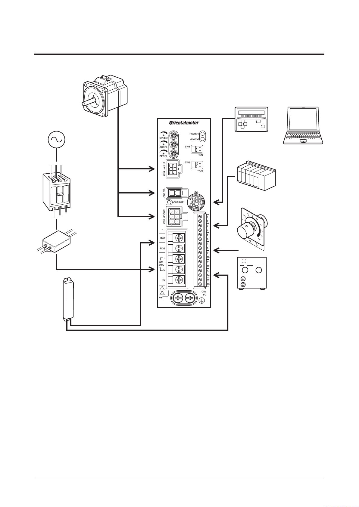
4 System conguration
Motor
System conguration
An example of system conguration using the
Driver
Connection
Power supply
Make sure power
supply voltage does
not exceed the rated
voltage.
Circuit breaker
or
earth leakage
cable
(supplied or
accessory)
Motor signal
connector
Electromagnetic
brake
connector
breaker
Always connect
a breaker to protect
the primary circuit.
Motor power
connector
Mains filter
Use an AC line filter to
eliminate noise. It effectively
reduces noise generated from
the power source or driver.
Regeneration unit
EPRC-400P (accessory)
Use this regeneration unit
when using the motor in
operation such as vertical
drive (gravitational operation)
or a large inertial load drive.
Series electromagnetic brake type is shown below.
BLE
Data setter OPX-2A
(accessory)
Or
Support software
MEXE02
Or
External control
equipment
Connect I/O signals.
External
potentiometer
(supplied)
Connect this to set the
motor speed externally.
External DC voltage
Connect an appropriate
power supply to set
the motor speed using
DC voltage.
−7−
Page 8

Preparation
BLE 5 12 A M 5 S - 1
Series name
5 Preparation
This chapter explains the items you should check, as well as the names and functions of each part.
5.1 Checking the product
Verify that the items listed below are included. Report any missing or damaged items to the branch or sales ofce
from which you purchased the product.
Verify the model number of the purchased product against the number shown on the package label.
Check the model number of the motor, gearhead, driver against the number shown on the nameplate.
Model names for motor, gearhead, driver combinations are listed in section “5.3 Combination tables.”
•Motor ........................................................ 1 unit
(with a gearhead, only for combination type)
•Driver ........................................................ 1 unit
•Connection cable .....................................1 pc.
(Only models with a supplied connection cable)
•Operating manual (this manual) ...............1 copy
•External potentiometer ............................. 1 pc.
•Signal cable for external potentiometer....1 pc.
[1 m (3.3 ft.)]
5.2 How to identify the product model
Number: Length (m) of a supplied connection cable
None: Without a supplied connection cable
Gearhead type for combination type S : Parallel shaft gearhead
F : Hollow shaft flat gearhead
Number: Gear ratio for combination type
A: Round shaft type
M : Electromagnetic brake type
None : Standard type
Motor size 2 : 60 mm (2.36 in.) sq.
4 : 80 mm (3.15 in.) sq.
5 : 90 mm (3.54 in.) sq.
Power supply voltage A : Single-phase 100-120 V
C : Single-phase 200-240 V
S : Three-phase 200-240 V
Output power 3 : 30 W
6 : 60 W
12 : 120 W
Accessories for combination type parallel shaft
gearhead
•Hexagonal socket head screw set ...............1 set
(Hexagonal socket head screw, at washer, spring
washer and nut, 4 pcs. each)
•Parallel key...................................................1 pc.
Accessories for combination type hollow shaft
at gearhead
•Hexagonal socket head screw set ...............1 set
(Hexagonal socket head screw, at washer, spring
washer and nut, 4 pcs. each)
•Safety cover .................................................1 pc.
•Safety cover mounting screw .......................2 pcs.
•Parallel key...................................................1 pc.
−8−
Page 9

5.3 Combination tables
in the model names indicates a number representing the gear ratio.
indicates a number representing the length of a connection cable.
The combination types come with the motor and gearhead pre-assembled.
Standard type
Motor type Model Motor model Gearhead model Driver model
Combination type
parallel shaft gearhead
Combination type
hollow shaft at
gearhead
Round shaft type
BLE23ASBLE23CSBLE23SSBLE46ASBLE46CSBLE46SSBLE512ASBLE512CSBLE512SSBLE23AFBLE23CFBLE23SFBLE46AFBLE46CFBLE46SFBLE512AFBLE512CFBLE512SFBLE23AABLE23CABLE23SABLE46AABLE46CABLE46SABLE512AABLE512CABLE512SA-
Preparation
BLEM23-GFS GFS2G
BLEM46-GFS GFS4G
BLEM512-GFS GFS5G
BLEM23-GFS GFS2GFR
BLEM46-GFS GFS4GFR
BLEM512-GFS GFS5GFR
BLEM23-A
BLEM46-A
BLEM512-A
−
−
−
−
−
−
−
−
−
BLED3A
BLED3C
BLED3S
BLED6A
BLED6C
BLED6S
BLED12A
BLED12C
BLED12S
BLED3A
BLED3C
BLED3S
BLED6A
BLED6C
BLED6S
BLED12A
BLED12C
BLED12S
BLED3A
BLED3C
BLED3S
BLED6A
BLED6C
BLED6S
BLED12A
BLED12C
BLED12S
Electromagnetic brake type
Motor type Model Motor model Gearhead model Driver model
BLE23AMSBLE23CMSBLE23SMS-
Combination type
parallel shaft gearhead
Combination type
hollow shaft at
gearhead
Round shaft type
BLE46AMSBLE46CMSBLE46SMSBLE512AMSBLE512CMSBLE512SMSBLE23AMFBLE23CMFBLE23SMFBLE46AMFBLE46CMFBLE46SMFBLE512AMFBLE512CMFBLE512SMFBLE23AMABLE23CMABLE23SMABLE46AMABLE46CMABLE46SMABLE512AMABLE512CMABLE512SMA-
BLEM23M2-GFS GFS2G
BLEM46M2-GFS GFS4G
BLEM512M2-GFS GFS5G
BLEM23M2-GFS GFS2GFR
BLEM46M2-GFS GFS4GFR
BLEM512M2-GFS GFS5GFR
BLEM23M2-A
BLEM46M2-A
BLEM512M2-A
−
−
−
−
−
−
−
−
−
BLED3AM
BLED3CM
BLED3SM
BLED6AM
BLED6CM
BLED6SM
BLED12AM
BLED12CM
BLED12SM
BLED3AM
BLED3CM
BLED3SM
BLED6AM
BLED6CM
BLED6SM
BLED12AM
BLED12CM
BLED12SM
BLED3AM
BLED3CM
BLED3SM
BLED6AM
BLED6CM
BLED6SM
BLED12AM
BLED12CM
BLED12SM
−9−
Page 10
Preparation
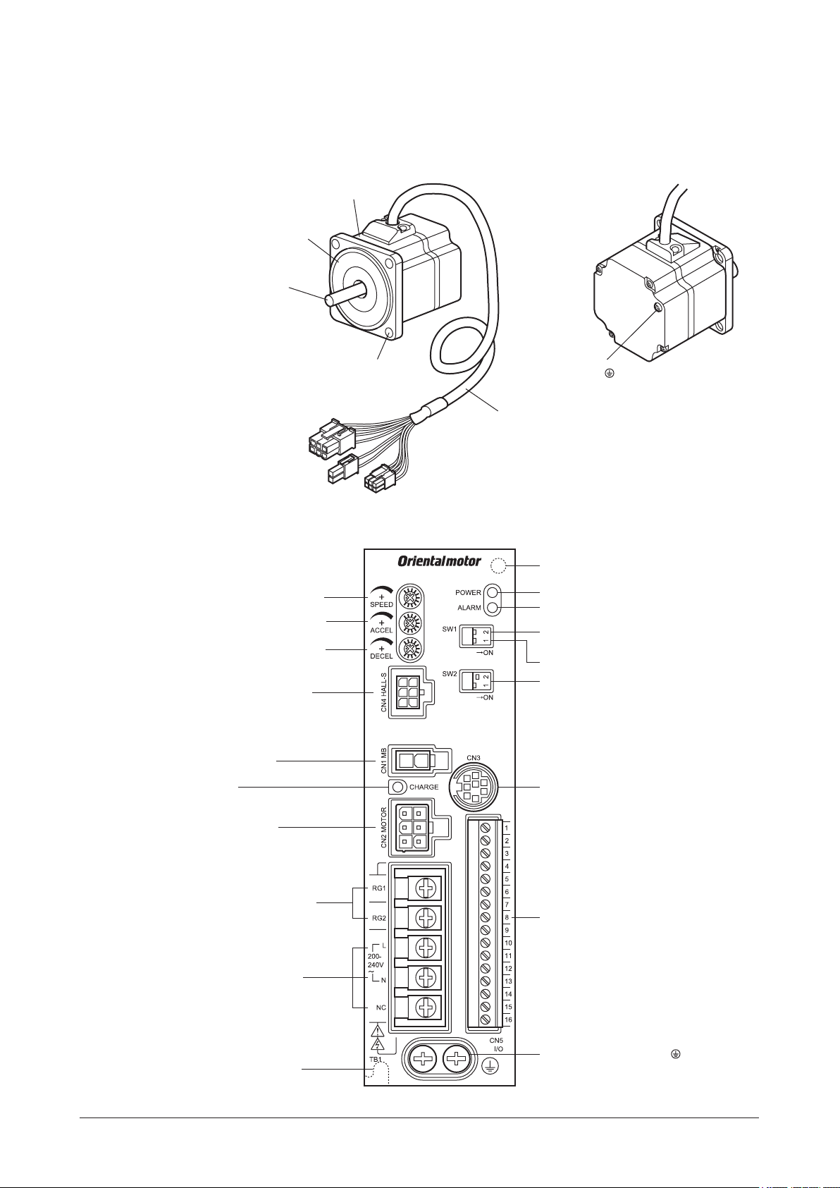
5.4 Names and functions of parts
This section explains the name and function of each part of the motor and driver.
Motor
Illustration shows the electromagnetic brake type.
Motor
Pilot
Output shaft
Mounting hole
(4 locations)
Motor power connector
Protective
Earth Terminal
Motor cable
Electromagnetic brake connector
Driver
Internal potentiometer (SPEED)
Acceleration time potentiometer
(ACCEL)
Deceleration time potentiometer
(DECEL)
Motor signal connector (CN4)
Electromagnetic brake
connector (CN1)
CHARGE LED
Motor connector (CN2)
∗
Motor signal connector
Mounting hole (at the back)
POWER LED (green)
ALARM LED (red)
FBLⅡcompatible mode setting switch
(SW1-2)
Not used (SW1-1)
External voltage selection switch
(SW2-1, SW2-2)
Communication connector (CN3)
−10−
Regeneration resistor terminal
(RG1, RG2)
Power supply input terminal
Mounting hole (at the back)
I/O signal connector (CN5)
Protective Earth Terminal
Electromagnetic brake type only
*
Page 11

Preparation
Name Explanation Ref.
Internal potentiometer Set the operating speed of the motor. P.39
Acceleration time potentiometer Set the acceleration time when starting the motor. P.41
Deceleration time potentiometer Set the deceleration time when stopping the motor. P.41
POWER LED (green) Lit while the main power is input. −
ALARM LED (red) Blinks when a protective function is triggered. P.48
Motor signal connector [CN4]
Connect the motor signal connector on the motor cable or
connection cable.
P.27
SW1-1: Not used. Keep this switch OFF. −
FBL
compatible mode setting
Ⅱ
switch (SW1)
SW1-2: Set the
ON: The
OFF: The
FBL
compatible mode.
FBL
FBL
Ⅱ
compatible mode is enabled.
Ⅱ
compatible mode is disabled (factory setting).
Ⅱ
P.44
SW2-1: Select whether to use an external power supply or the
driver’s built-in power supply. When controlling the operation
External voltage selection
switch (SW2)
using relays, switches, etc., select the driver’s built-in power
supply.
ON: Driver’s built-in power supply
OFF: External power supply (factory setting)
P.29
SW2-2: When setting the speed via external DC voltage, change
the setting according to the external DC voltage.
ON: 5 VDC (factory setting)
P.39
OFF: 10 VDC
Electromagnetic brake
connector [CN1]
Connect the electromagnetic brake connector on the motor cable
or connection cable.
P.27
Lit while the main power is input. After the main power has been
CHARGE LED (red)
turned off, the LED will turn off once the residual voltage in the
−
driver drops to a safe level.
Motor connector [CN2]
Regeneration resistor terminal
(TB1) [RG1, RG2]
Connect the motor power connector on the motor cable or
connection cable.
Connect the accessory regeneration unit
EPRC-400P
(sold
separately).
P.27
P.28
Connect to the main power supply.
•Single-phase 100-120 V
L, N: Connect a single-phase 100-120 VAC
Power supply input terminal
(TB1) [L, N] [L1, L2, L3]
NC: Not used.
•Single-phase 200-240 V
L, N: Connect a single-phase 200-240 VAC
P.26
NC: Not used.
•Three-phase 200-240 V
L1, L2, L3: Connect a three-phase 200-240 VAC
Communication connector
[CN3]
Connect the
OPX-2A
(accessory) or
MEXE02
. P.34
•Use this connector when using an external power supply for I/O
signals. (24 VDC −15% to +20%)
I/O signal connector [CN5]
•Connect the I/O signals from the programmable controller.
•Connect the thermostat output of the accessory regeneration
EPRC-400P
unit
(sold separately).
P.29
•Connect the external potentiometer (supplied).
Protective Earth Terminal
Mounting holes
(two locations at the back)
Ground this terminal using a grounding wire of AWG18 to 14
(0.75 to 2.0 mm
2
).
These mounting holes are used to install the driver with screws
(M4).
P.26
P.20
−11−
Page 12
Installation
Rear
6 Installation
This chapter explains the installation location and installation methods of the motor and driver, as well as how to
install a load and external potentiometer. Also covered in this section are the installation and wiring methods that are
in compliance with the relevant EMC Directive.
6.1 Installation location
The motor and driver are designed and manufactured for use as internal components of equipment.
Install the motor and driver in a well-ventilated place where they can be inspected easily and the following conditions
are satised:
•Inside an enclosure installed indoors (provide a
ventilation hole)
•Ambient temperature: 0 to +50 °C
(+32 to +122 °F) (non-freezing)
•Ambient humidity: 85% or less (non-condensing)
•Area not exposed to direct sun
•Area free of excessive amount of dust, iron
particles or the like
•Area free of excessive salt
•Area that is free of explosive atmosphere or toxic gas
(such as sulfuric gas) or liquid
•Area not subject to splashing water (rain, water droplets),
oil (oil droplets) or other liquids
•Area not subject to continuous vibration or excessive
shocks
•Area free of excessive electromagnetic noise (from
welders, power machinery, etc.)
•Area free of radioactive materials, magnetic elds or
vacuum
6.2 Installation overview
This section explains an overview of how to install the motor and driver. Refer to each applicable section for details.
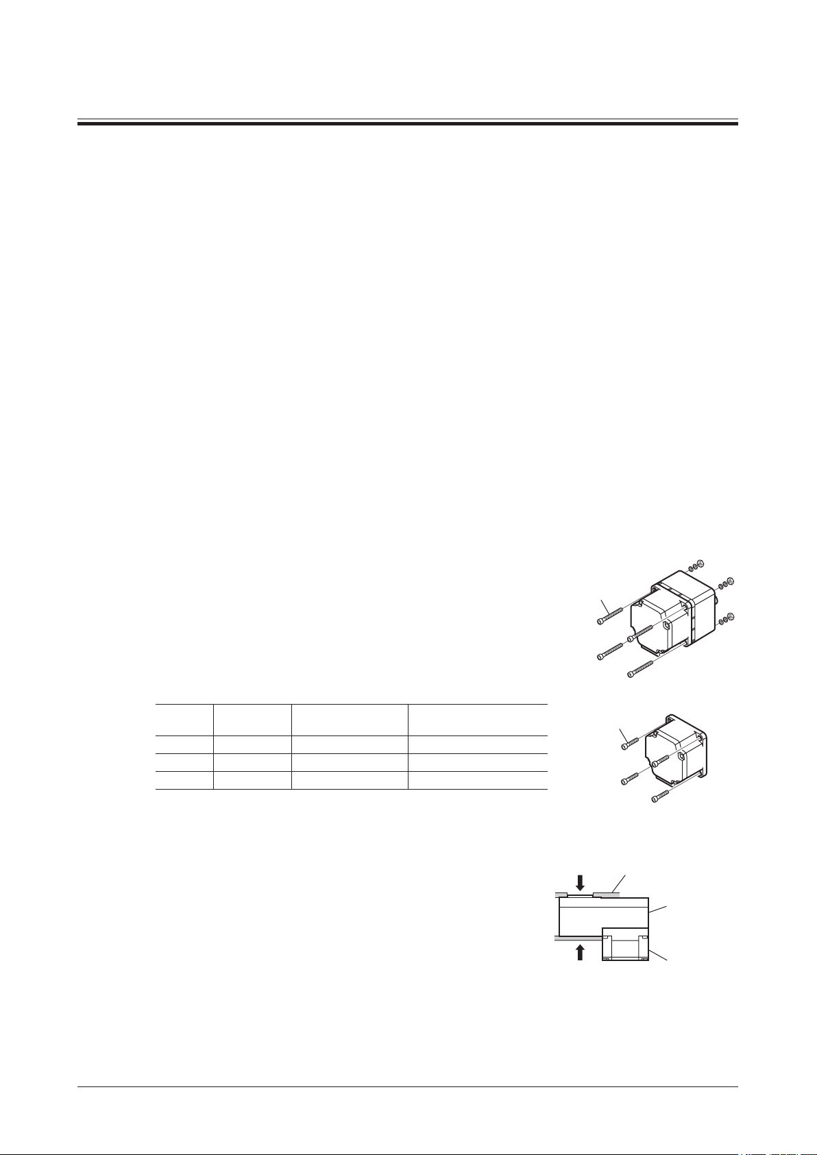
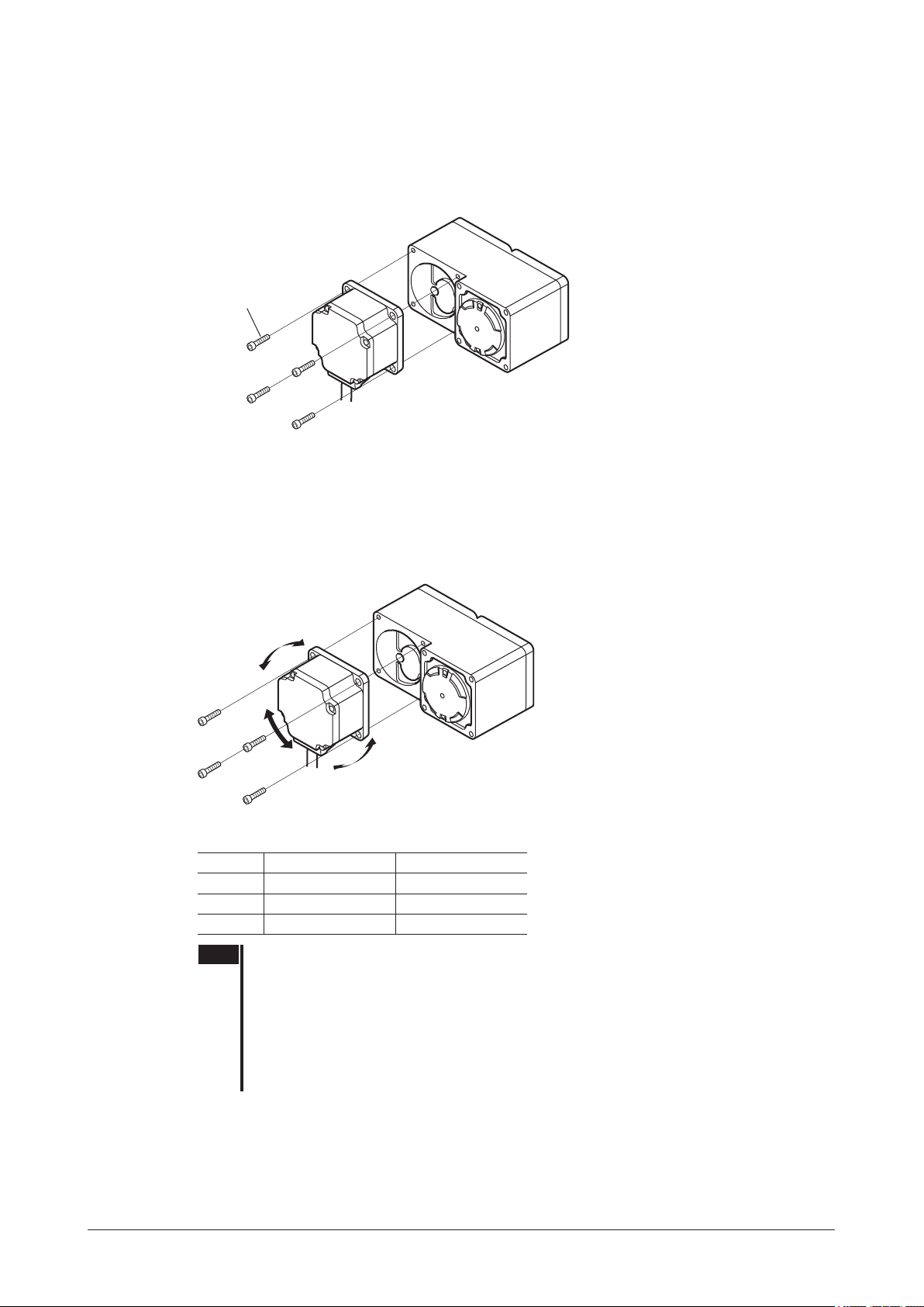
Installing the combination parallel shaft gearhead or round shaft type
Install the hexagonal socket head screw in the four mounting holes you
drilled and tighten the nuts until no gaps remain between the motor and
mounting plate.
The combination type parallel shaft gearheads come with a set of hexagonal
socket head screws. Round shaft types do not come with hexagonal socket
head screws. Hexagonal socket head screws must be provided by the
customer if a round shaft type is used.
Refer to p.13 for the machining dimensions of the mounting plate and how to
install/remove the gearhead.
Hexagonal socket head screw set
(supplied with the combination type parallel shaft gearhead)
Model
BLE23
BLE46
BLE512
The gures in the table apply when the supplied hexagonal socket head screw
*
set is used.
Installing the combination type hollow shaft at gearhead
A combination type hollow shaft at gearhead can be installed by using
either its front or rear side as the mounting surface. Install the supplied
hexagonal socket head screw set in the four mounting holes you drilled and
tighten the nuts until no gaps remain between the motor and mounting plate.
Also, attach the supplied safety cover to the hollow output shaft on the end
opposite from the one where the load shaft is installed.
Refer to p.14 for the installation method and how to install/remove the
gearhead.
Nominal
thread size
M4 1.8 N·m (15.9 lb-in) 5 mm (0.20 in.)
M6 6.4 N·m (56 lb-in) 8 mm (0.31 in.)
M8 15.5 N·m (137 lb-in) 12 mm (0.47 in.)
Tightening torque
Maximum applicable
plate thickness
*
• Combination parallel shaft
gearhead
Hexagonal socket
head screw set
(supplied)
• Round shaft type
Hexagonal socket
head screw
Front Mounting plate
Hollow shaft
flat gearhead
Motor
−12−
Page 13
Hexagonal socket head screw set (supplied)
Pilot section
Model
BLE23
BLE46
BLE512
The gures in the table apply when the supplied hexagonal socket head screw set is used.
*
Installing the driver
Nominal
thread size
M5 3.8 N·m (33 lb-in) 5 mm (0.20 in.)
M6 6.4 N·m (56 lb-in) 8 mm (0.31 in.)
M8 15.5 N·m (137 lb-in) 12 mm (0.47 in.)
Tightening torque
The driver can be installed in two different ways. Refer to p.20 for the specic installation methods.
•Use screws (M4: not supplied) to afx the driver through the mounting holes (two locations) provided at the back
of the driver.
•Afx the driver on a DIN rail using the accessory DIN-rail mounting plate (sold separately).
Maximum applicable
plate thickness
*
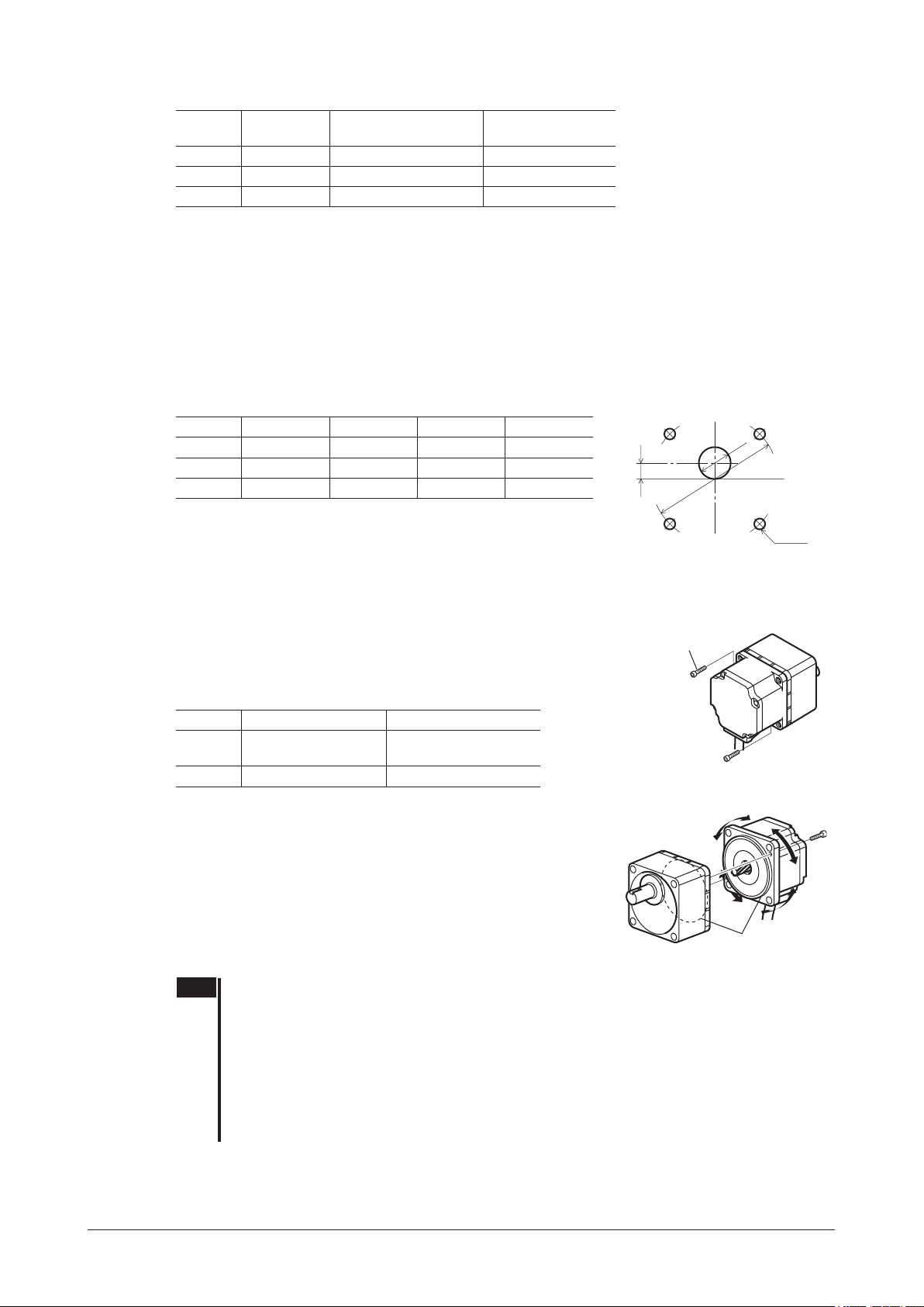
6.3 Installing the combination parallel shaft gearhead
Mounting hole dimensions [unit: mm (in.)].
Model ØA ØB C ØD
BLE23
BLE46
BLE512
ØB indicates the external dimensions of the product.
Drill holes with a minimum diameter of ØB +1 mm (0.04 in.).
70 (2.76) 24 (0.94) 10 (0.39) 4.5 (0.177)
94 (3.70) 34 (1.34) 13 (0.51) 6.5 (0.256)
104 (4.09) 40 (1.57) 18 (0.71) 8.5 (0.335)
Installation
ØB
C
ØA
4×ØD
Removing/Installing the gearhead
To replace the gearhead or change the cable outlet direction, remove the screws assembling the gearhead. The
gearhead can be removed and the motor cable position changed to a desired 90° direction.
1.
Remove the hexagonal socket head screws (2 pcs.) assembling
the motor and gearhead and detach the motor from the
gearhead.
Hexagonal
socket head
screw
Assembly screws
Model Nominal thread size Tightening torque
BLE23
BLE46
BLE512
2.
Using the pilot sections of the motor and gearhead as guides,
install the gearhead to the motor and tighten the hexagonal
socket head screws.
At this time, the motor cable position can be changed to a desired 90°
direction.
When installing the gearhead, slowly rotate it clockwise/
counterclockwise to prevent the pinion of the motor output shaft from
contacting the side panel or gear of the gearhead.
Also conrm that no gaps remain between the motor ange surface and
the end face of the gearhead’s pilot section.
Note •Do not forcibly assemble the motor and gearhead. Also, do not let metal objects or other foreign
matter enter the gearhead. The pinion or gear of the motor output shaft may be damaged,
resulting in noise or shorter service life.
•Do not allow dust to attach to the pilot sections of the motor and gearhead. Also, assemble the
motor and gearhead carefully by not pinching the O-ring at the motor’s pilot section. If the O-ring
is crushed or severed, grease may leak from the gearhead.
•The hexagonal socket head screws assembling the motor and gearhead are afxing the motor
and gearhead only temporarily. When installing the gearhead, be sure to use the supplied
hexagonal socket head screws (4 pcs.).
M2.6 0.4 N·m (3.5 lb-in)
M3 0.6 N·m (5.3 lb-in)
Change the cable
position to a desired
90° direction.
−13−
Page 14
Installation
+ 0.030
+ 0.0012
+ 0.030
+ 0.0012
+ 0.035
+ 0.0014
6.4 Installing the round shaft type
Install the motor to a mounting plate of the following size or larger, so that the motor case temperature will not exceed
90 °C (194 °F).
Model Size of mounting plate Thickness Material
BLE23
BLE46
BLE512
Electromagnetic brake type: 135×135 mm (5.31×5.31 in.)
*
Mounting hole dimensions [unit: mm (in.)]
Model ØA B ØCH7 ØD
BLE23
BLE46
BLE512
ØC indicates the pilot diameter on the ange.
Note Fit the boss on the gearhead mounting surface into a pilot receiving hole.
115×115 mm (4.53×4.53 in.)
135×135 mm (5.31×5.31 in.)
165×165 mm (6.50×6.50 in.)
70 (2.76) 49.5 (1.949)
94 (3.70) 66.47 (2.617)
104 (4.09) 73.54 (2.895)
*
5 mm (0.20 in.) Aluminum
54
(2.1260
73
(2.8740
83
(3.2677
0
0
0
0
0
0
)
)
)
4.5 (0.177)
6.5 (0.256)
8.5 (0.335)
B
ØA
ØCH7
B
ØD
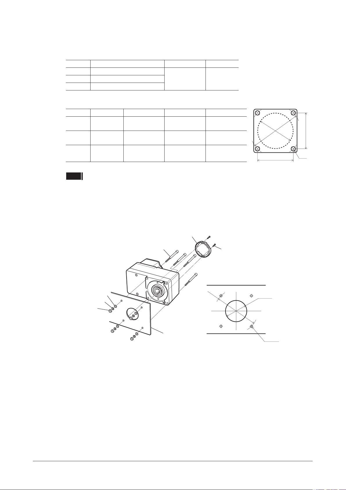
6.5 Installing the combination type hollow shaft at gearhead
Using the front side as the mounting surface
When the gearhead is installed by using its front side as the mounting surface, use the boss of the output shaft to align
the center.
Safety cover
Hexagonal socket head screw
• Mounting hole dimension
Flat washer
Spring washer
Hexagonal nut
Mounting plate
Safety cover
mounting screw (M3)
ØA
ØBH8
4×ØC
−14−
Page 15
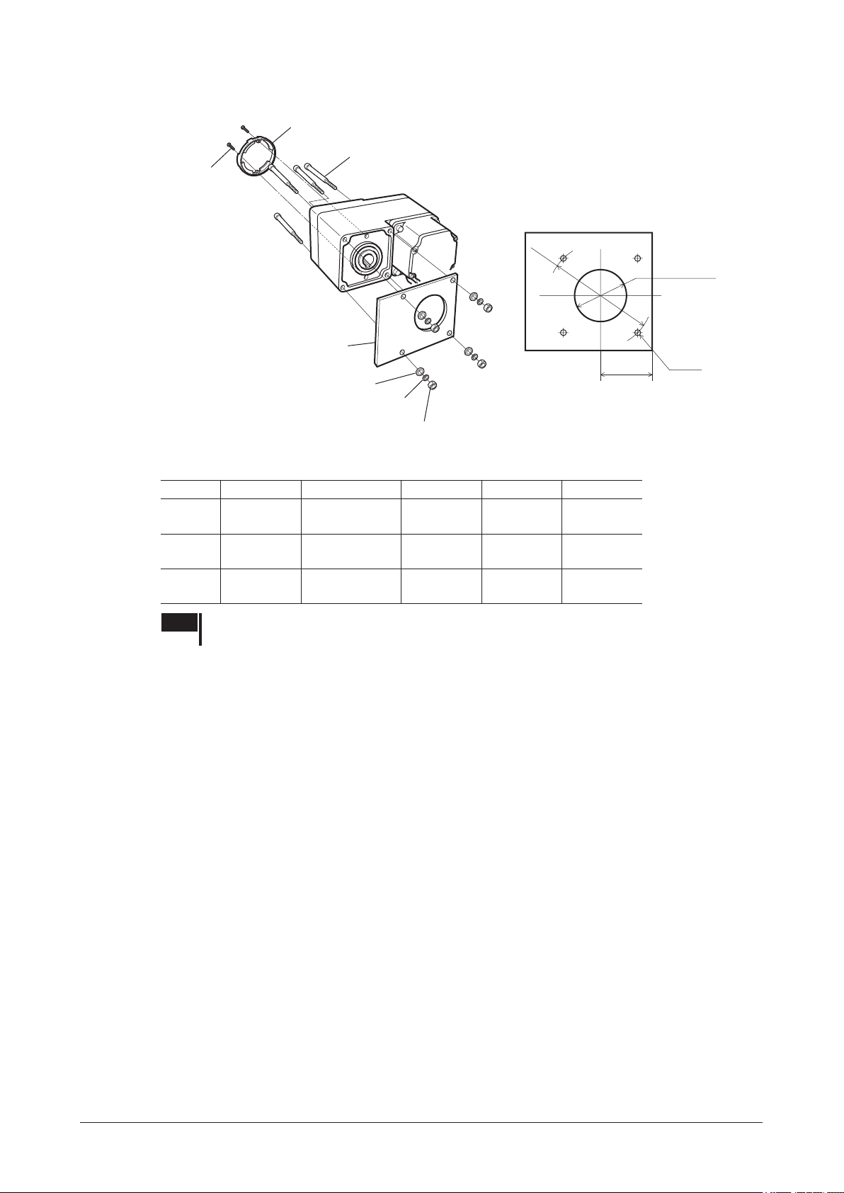
Using the rear side as the mounting surface
+ 0.039
+ 0.0015
+ 0.039
+ 0.0015
Safety cover
Hexagonal socket head screw
Safety cover
mounting screw (M3)
Installation
• Mounting hole dimension
ØA
ØD or more
Mounting plate
E
4×ØC
Flat washer
Spring washer
Hexagonal nut
Mounting hole dimensions [Unit: mm (in.)]
Model ØA ØBH8 ØC ØD E
BLE23
BLE46
BLE512
70 (2.76)
94 (3.70)
104 (4.09)
Note When installing the gearhead by using its rear side as the mounting surface, prevent contact
between the mounting plate and motor by keeping dimension E below the specied value.
34
(1.34
38
(1.50
50
(1.97
+ 0.039
0
+ 0.0015
0
0
0
0
0
5.5 (0.22) 25 (0.98) 29 (1.14)
)
6.5 (0.26) 30 (1.18) 39 (1.54)
)
8.5 (0.33) 35 (1.38) 44 (1.73)
)
−15−
Page 16
Installation
90° direction.
Removing/Installing the gearhead
To replace the gearhead or change the cable outlet direction, remove the screws assembling the gearhead.
The gearhead can be removed and the motor cable position changed to one of three 90° directions.
Note that the motor cable cannot be positioned in the direction where the cable faces the gearhead output shaft.
1.
Remove the hexagonal socket head screws (4 pcs.) attaching the gearhead and motor and detach the
motor from the gearhead.
Hexagonal socket
head screw
2.
Using the pilot sections of the motor and gearhead as guides, install the motor to the gearhead and
tighten the hexagonal socket head screws.
At this time, the motor cable position can be changed to one of three 90° directions.
Install the motor carefully to prevent the pinion of the motor output shaft from contacting the casing or gear of the
gearhead.
Also conrm that no gaps remain between the motor ange surface and the end face of the gearhead’s pilot
section.
Change the cable
position to a desired
Assembly screws
Model Nominal thread size Tightening torque
BLE23
BLE46
BLE512
Note •Do not forcibly assemble the motor and gearhead. Also, do not let metal objects or other
foreign matters enter the gearhead. The pinion or gear of the motor output shaft may be
damaged, resulting in noise or shorter service life.
•Do not allow dust to attach to the pilot sections of the motor and gearhead. Also, assemble
the motor carefully by not pinching the O-ring at the motor’s pilot section. If the O-ring is
pinched, the coupling strength will drop and grease may leak from the gearhead.
•The motor cable position cannot be changed to the direction where the cable faces the
gearhead output shaft, because the gearhead case will obstruct the cable.
M4 1.8 N·m (15.9 lb-in)
M6 6.4 N·m (56 lb-in)
M8 15.5 N·m (137 lb-in)
−16−
Page 17

6.6 Installing a load
Combination type parallel gearhead or round shaft type
When installing a load on the motor (gearhead), align the center of the motor output shaft (gearhead output shaft) with
the center of the load shaft.
Note •When coupling the motor (gearhead) with a load, pay attention to centering, belt tension,
parallelism of pulleys, etc. Also, securely afx the tightening screws of the coupling or pulleys.
•When installing a load, do not damage the motor output shaft (gearhead output shaft) or
bearing. Forcing in the load by driving it with a hammer, etc., may break the bearing. Do not
apply any excessive force to the output shaft.
•Do not modify or machine the motor (gearhead) output shaft. The bearing may be damaged or
motor (gearhead) may break.
Output shaft shape
z
Combination type parallel shaft gearhead
A key groove is provided on the output shaft of each combination type parallel shaft gearhead. Form a key groove on
the load side and afx the load using the supplied parallel key.
Round shaft type
A at section is provided on the motor output shaft of each round shaft type. Apply a double-point screw, etc., at the
at section to securely afx the load and prevent it from spinning.
Installation
How to install a load
z
Using a coupling
Align the centerline of the motor (gearhead) output shaft with the centerline of the load shaft.
Using a belt
Adjust the motor (gearhead) output shaft to lie parallel with the load shaft and form right angles between the output
shaft/load shaft and the line connecting the centers of both pulleys.
Using a gear
Adjust the motor (gearhead) output shaft to lie parallel with the gear shaft and allow the output shaft to mesh correctly
with the centers of the gear teeth.
When using the output axis tip screw hole of a gearhead
Use a screw hole provided at the tip of the output shaft as an auxiliary
means for preventing the transfer mechanism from disengaging.
(
GFS2G
The square box in the gearhead model will contain a value representing the
*
gear ratio.
type have no output shaft tip screw hole.)
Gearhead model name
GFS4G
GFS5G
*
Effective depth 10 mm (0.39 in)
Effective depth 12 mm (0.47 in)
Output shaft tip screw hole
M5
M6
The example of output axis tip screw
hole use
Transmission parts
Fixed screw
Spacer
Screw
−17−
Page 18

Installation
Combination type hollow shaft at gearhead
If the motor is subject to a strong impact upon instantaneous stop or receives a large radial load, use a stepped load
shaft.
Note Apply grease (molybdenum disulde grease, etc.) on the surface of the load shaft and inner walls
of the hollow output shaft to prevent seizure.
Stepped load shaft
z
Afxing method using retaining ring
Install each hexagonal socket head screw over a retaining ring, spacer, at washer and spring washer and securely
afx the ring.
Hexagonal socket head screw
Spring washer
Flat washer
Spacer
Retaining ring
Parallel key
Stepped load shaft
Hollow output shaft Flat washer
Load shaft
ØD
Parallel key
Retaining ring
Hexagonal
socket
headscrew
Spring washer
Spacer
Afxing method using end plate
Afx the load shaft by tightening the hexagonal socket head screw over an end plate, at washer and spring washer.
Hexagonal socket head screw
Spring washer
Hollow output shaft
ØD
Flat washer
Hexagonal socket
head screw
Parallel key
Flat washer
End plate
Load shaft
−18−
Spring washer
Parallel key
Stepped load shaft
End plate
Note The safety cover (supplied) cannot be attached due to contact between the safety cover and
hexagonal socket head screw. Take safety measures against rotating part.
Page 19

Installation
+ 0.027
+ 0.0011
0
0
+ 0.033
+ 0.0013
0
0
Non-stepped load shaft
z
Install each hexagonal socket head screw over a retaining ring, spacer, at washer and spring washer and securely
afx the ring. Also insert a spacer on the load shaft side.
Spacer
Retaining
ring
Hexagonal socket
head screw
Spring washer
Flat washer
Load shaft
Retaining ring
Hollow output shaft
Flat washer
Hexagonal
socket head
screw
Parallel key
Load shaft
Spacer
Recommended load shaft installation dimensions [Unit: mm (in.)]
z
Nominal
diameter of
retaining ring
Ø12 (Ø0.47) M4 3 (0.12) 20 (0.79)
)
Ø15 (Ø0.59) M5 4 (0.16) 25 (0.98)
)
Ø20 (Ø0.79) M6 5 (0.20) 30 (1.18)
)
Model
BLE23
BLE46
BLE512
Inner diameter
of hollow shaft
(H8)
Ø12
0
(Ø0.4724
(Ø0.5906
(Ø0.7874
Ø15
Ø20
0
+ 0.027
0
+ 0.0011
0
0
0
Recommended
diameter of load
shaft (h7)
Ø12
)
(Ø0.4724
Ø15
)
(Ø0.5906
Ø20
)
(Ø0.7874
-
0
-
-
0.018
-
0.018
0
-
0.021
-
0.0007
0.0007
0.0008
Parallel key
Applicable
screw
Spacer
Spacer
thickness
Spring washer
Spacer
Outer
diameter of
stepped shaft
(ØD)
6.7 Permissible radial load and permissible axial load
Make sure the radial load and axial load received by the motor (gearhead) output shaft will not exceed the allowable
values shown in the table below.
Note If the radial load or axial load exceeds the specied allowable value, repeated load applications
may cause the bearing or output shaft of the motor (gearhead) to undergo a fatigue failure.
Combination type parallel shaft gearhead
z
Model
Gear ratio 10 mm (0.39 in.) 20 mm (0.79 in.)
5 100 (22) [90 (20)] 150 (33) [110 (24)]
BLE23
30 to 200 200 (45) [180 (40)] 300 (67) [230 (51)]
5 200 (45) [180 (40)] 250 (56) [220 (49)]
BLE46
30 to 200 450 (101) [420 (94)] 550 (123) [500 (112)]
5 300 (67) [230 (51)] 400 (90) [300 (67)]
BLE512
30 to 200 500 (112) [450 (101)] 650 (146) [550 (123)]
The values assume a rated speed of 3000 r/min or below. The values in [ ] are based on a rated speed of 4000 r/min.
*
Distance from tip of gearhead output shaft and
permissible radial load* [N (lb.)]
Permissible
axial load
[N (lb.)]
40 (9)10 to 20 150 (33) [130 (29)] 200 (45) [170 (38)]
100 (22)10 to 20 300 (67) [270 (60)] 350 (78) [330 (74)]
150 (33)10 to 20 400 (90) [370 (83)] 500 (112) [430 (96)]
−19−
Page 20
Installation
(at the back)
Combination type
z
hollow shaft at gearhead
Model
Gear ratio 10 mm (0.39 in.) 20 mm (0.79 in.)
BLE23
BLE46
BLE512
The values assume a rated speed of 3000 r/min or below. The values in [ ] are based on a rated speed of 4000 r/min.
*
Round shaft type
z
Model
BLE23
BLE46
BLE512
Minimize the axial load. If a axial load must be applied, do not let it exceed one-half the motor’s mass.
*
5, 10 450 (101) [410 (92)] 370 (83) [330 (74)]
15 to 200 500 (112) [460 (103)] 400 (90) [370 (83)]
5, 10 800 (180) [730 (164)] 660 (148) [600 (135)]
15 to 200 1200 (270) [1100 (240)] 1000 (220) [910 (200)]
5, 10 900 (200) [820 (184)] 770 (173) [700 (157)]
30 to 200 1500 (330) [1400 (310)] 1280 (280) [1200 (270)]
Distance from tip of motor output shaft and
permissible radial load [N (lb.)]
10 mm (0.39 in.) 20 mm (0.79 in.)
80 (18) 100 (22)
110 (24) 130 (29)
150 (33) 170 (38)
Distance from gearhead mounting surface and
permissible radial load* [N (lb.)]
Permissible axial load
[N (lb.)]
Not to exceed one-half the
motor’s dead weight
Permissible
axial load
[N (lb.)]
200 (45)
400 (90)
500 (112)15, 20 1300 (290) [1200 (270)] 1110 (240) [1020 (220)]
*
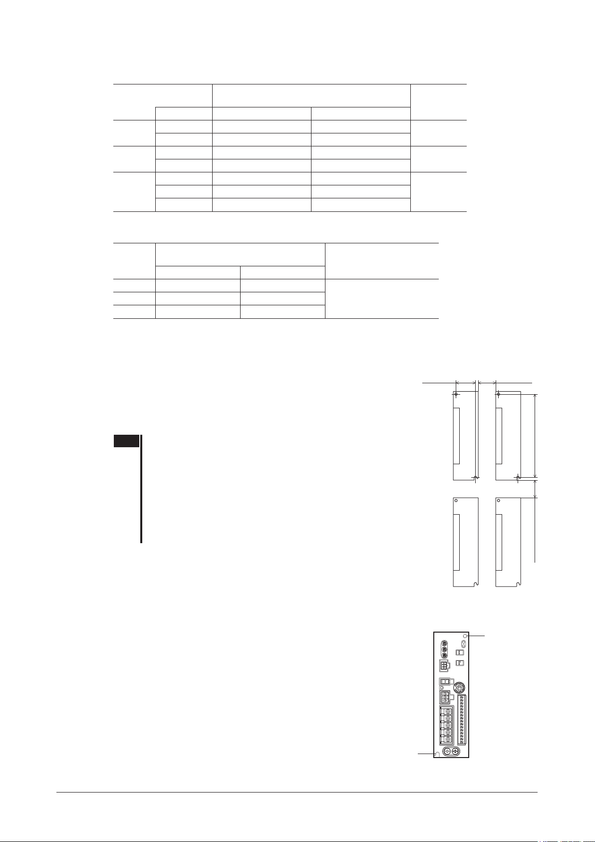
6.8 Installing the driver
The driver is designed so that heat is dissipated via air convection and conduction
through the enclosure. Install the driver to a at metal plate offering excellent
vibration resistance.
When two or more drivers are to be installed side by side, provide 20 mm
(0.79 in.) and 25 mm (0.98 in.) clearances in the horizontal and vertical
directions, respectively.
Note •Install the driver in an enclosure whose pollution degree is 2 or
above or protection class is IP54 or better.
•Be sure to install (position) the driver vertically. Do not block the
radiation openings.
•Do not install any equipment that generates a large amount of
heat or noise near the driver.
•If the ambient temperature of the driver exceeds 50 °C (122 °F),
revise the ventilation condition or force-cool the area around the
driver using a fan.
Installing with screws
Install the driver perpendicularly (vertical position) and afx the
driver through the mounting holes using two screws (M4: not
supplied).
35 (1.38)
20 (0.79)
or more
150 (5.91)
25 (0.98) or more
Unit: mm (in.)
Mounting hole
(at the back)
Mounting hole
−20−
Page 21

Mounting to DIN rail
DIN lever
When mounting the driver to a DIN rail, use a separately sold DIN rail mounting plate (model number:
attach it to a 35 mm (1.38 in.) wide DIN rail.
1.
Attach the DIN rail mounting plate (model number:
PADP03
supplied with the plate.
Tightening torque: 0.3 to 0.4 N·m (2.6 to 3.5 lb-in)
2.
Pull the DIN lever down, engage the upper tab of the
DIN rail mounting plate over the DIN rail, and push the
DIN lever until it locks in place.
) to the back of the driver using the screws
DIN rail mounting
plate
Mounting holes
(M3, four locations)
Mounting screws
(supplied)
Tab
DIN rail
Installation
PADP03
) and
3.
Use an end plate (not supplied) to secure the driver.
Removing from DIN rail
z
Pull the DIN lever down until it locks using a at tip screwdriver, and lift the bottom of
the driver to remove it from the rail.
Use force of about 10 to 20 N (2.2 to 4.5 lb.) to pull the DIN lever to lock it. Excessive
force may damage the DIN lever.
Note
•Do not use the mounting holes (M3, four locations) for the DIN rail
mounting plate provided in the back of the driver for any purpose
other than securing the DIN rail mounting plate.
•Be sure to use the supplied screws when securing the DIN rail
mounting plate. The use of screws that would penetrate 3 mm
(0.12 in.) or more through the surface of the driver may cause
damage to the driver.
DIN lever
End plate
−21−
Page 22

Installation
0.45 N·m (3.9 lb-in)
6.9 Installing the regeneration unit (accessory)
Install the accessory regeneration unit
EPRC-400P
separately) in a location where heat dissipation capacity
equivalent to a level achieved with a heat sink [made of
aluminum, 350×350×3 mm (13.78×13.78×0.12 in.)] is
ensured.
Afx the
EPRC-400P
on a smooth metal plate offering high
heat conductivity, using two screws (M4, not supplied).
(sold
• Mounting hole dimension
[unit: mm (in.)]
Screw (M4)
6.10 Installing the external potentiometer (supplied)
Insert the external potentiometer as shown below.
Variable resistor
Insulation
sheet
Toothed washer
Tightening torque:
Mounting plate
Dial plate
Setscrew (M4)
Tightening torque:
0.4 N·m (3.5 lb-in)
Dial
Nut
• Reference mounting hole dimensions
[Unit: mm (in.)]
Ø3 (Ø0.12)
Regeneration
unit
EPRC-400P
7.5
Ø10 (Ø0.39)
±0.4 (0.30±0.02)
165 (6.50)
+ 0.3
Ø4.2
0
+ 0.012
(0.165 )
0
Soldering the variable resister terminal and the lead wires
Cover a heat-shrinkable tube over the soldered part to insulate.
Soldering condition: 235 °C (455 °F), less than 5 sec.
Dial
Variable resistor
Lead wire
Terminal
Lead wire
Heat-shrinkable tube
Solder (Pass the lead wire
through the terminal hole and
give it two or three turns.)
−22−
Page 23

6.11 Installing and wiring in compliance with EMC Directive
The
require that your mechanical equipment in which the
The installation/wiring methods of the motor and driver explained here represent the basic methods that are effective
in helping your mechanical equipment conform to the EMC Directive.
The nal level of conformance of your mechanical equipment to the EMC Directive will vary depending on the
control system equipment used with the motor/driver, conguration of electrical parts, wiring, layout, hazard level,
and the like. Therefore, you must conduct the EMC tests on your mechanical equipment to conrm compliance.
Series is designed and manufactured for use as an internal component of equipment. The EMC Directive
BLE
Series is installed satisfy the applicable requirements.
BLE
Installation
Without effective measures to suppress the electromagnetic interference (EMI) caused by the
surrounding control system equipment or the electromagnetic spectrum (EMS) generated by the
function of your mechanical equipment may be seriously affected.
The
Connecting a mains lter
Install a mains lter in the power line in order to prevent the noise generated within the driver from propagating
outside via the AC input line. For mains lters, use the products as shown in the chart, or an equivalent.
Overvoltage category II applies to mains lters.
Install the mains lter as close to the driver as possible, and use cable clamps and other means to secure the input and
output cables rmly to the surface of the enclosure. Connect the ground terminal of the mains lter to the grounding
point, using as thick and short a wire as possible.
Do not place the AC input cable (AWG18 to 14: 0.75 to 2.0 mm
to 14: 0.75 to 2.0 mm
directly coupled to the power supply cable by means of stray capacitance.
Connecting the AC power line reactor
When inputting single-phase 200-240 V, insert a reactor (5 A, 5 mH) in the AC power line to ensure compliance with
EN 61000-3-2.
Series will conform to the EMC Directive if installed/wired using the methods specied below.
BLE
Manufacturer
SOSHIN ELECTRIC CO., LTD HF2010A-UPF HF3010C-SZA
Schaffner EMC FN2070-10-06 FN3025HP-10-71
2
). Parallel placement will reduce mains lter effectiveness if the enclosure’s internal noise is
Single-phase 100-120 V
Single-phase 200-240 V
2
) parallel with the mains-lter output cable (AWG18
Three-phase 200-240 V
Series in the
BLE
Series, the
BLE
Connecting the control power supply
Use a control power supply conforming to the EMC Directive. Use a shielded cable for wiring and wire/ground the
control power supply over the shortest possible distance. Refer to “Wiring the power supply cable” for how to ground
the shielded cable.
Grounding procedure
The cable used to ground the motor, driver, mains lter and power supply cable (shielded cable) must be as thick
and short to the grounding point as possible so that no potential difference is generated. Choose a large, thick and
uniformly conductive surface for the grounding point. Refer to the p.26 for the recommended grounding method.
Wiring the power supply cable
Use a shielded cable of AWG18 to 14 (0.75 to 2.0 mm2) in diameter for the driver power supply cable and keep it as
short as possible.
Strip a part of the shielded cable and ground the stripped part using a metal cable clamp that contacts the stripped
cable around its entire circumference, or use a drain wire to make the
ground connection.
When grounding the shielded cable, connect both ends (mains lter
side and power supply side) to earth to prevent a potential difference
from generating in the shielded cable.
Shielded cable
Cable clamp
−23−
Page 24

Installation
Notes about installation and wiring
•Connect the motor/driver and other peripheral control equipment directly to the grounding point so as to prevent a
potential difference from developing between grounds.
•When relays or electromagnetic switches are used together with the system, use mains lters and CR circuits to
suppress surges generated by them.
•Keep cables as short as possible without coiling and bundling extra lengths.
•Wire the power lines such as the motor cable and power cable away from the signal cables by providing a minimum
clearance of 100 mm (3.94 in.) between them. If they must cross, do so at a right angle. Place the AC input cable
and output cable of a mains lter separately from each other.
•Use a connection cable (supplied or accessory) when extending the wiring distance between the motor and driver.
The EMC measures are conducted using the Oriental Motor connection cable.
Example of motor and driver installation and wiring
Regeneration unit
EPRC-400P
Motor
AC power
supply
L
N
PE
PE
Motor cable
∗2
Power supply cable
[2 m (6.56 ft.)]
PE PE
∗2
Regeneration unit lead wire
[0.3 m (0.98 ft.)]
Connection cable
[20 m (65.6 ft.)]
Ground plate (aluminum plate)
PE
∗3
∗1∗2
Mains filter
PE
Driver
PE
Cable
clamp
FG
I/O signals cable
[2 m (6.56 ft.)]
∗2
External
potentiometer
Performance has been evaluated based on connection cable lengths of up to 20 m (65.6 ft.). You can connect up to three
*1
connection cables.
Shielded cable
*2
Unshielded cable
*3
Precautions about static electricity
Static electricity may cause the driver to malfunction or become damaged. Do not come close to or touch the driver
while the power is on except when operating the switch of the front of driver.
To change the settings of driver switches, be sure to use an insulated screwdriver.
−24−
Page 25

7 Connection
This chapter explains how to connect the driver and motor, I/O signals, and power supply, as well as the grounding
method.
7.1 Connection example
The connection example below shows an example of a electromagnetic brake type single-phase 100 to 120 V driver
where the built-in power supply and supplied external potentiometer are used to set the speed. Refer to the applicable
pages for details.
Connection
PE
Motor signal connector
p.27
Motor
cable
Electromagnetic brake
connector
Connect to CN1
Motor power connector
Connect to CN2
p.27
Power supply connection
Single-phase 100 to 120 V
-
15 to +10% 50/60 Hz
For 200 V specificaion;
Single-phase 200 to 240 V
-
15 to +10% 50/60 Hz
Three-phase 200 to 240 V
-
15 to +10% 50/60 Hz
Connect to CN4
Connection
cable
∗2
p.26
SW1-2: Set the FBL䊡compatible mode.
ON: The FBL䊡compatible mode is enabled.
OFF: The FBL
(factory setting).
䊡compatible mode is disabled
SW1-1: Not use.
SW2-2㻦㻌Set this switch when setting the speed
externally.
ON: The supplied external potentiometer or external
DC voltage is used to set the speed at 5 VDC
(factory setting).
OFF: DC voltage is used to set the speed at 10 VDC.
p.39
SW2-1: Set the I/O signal power supply.
ON: When relays, switches, etc., are used to control
the operation (driver's built-in power supply).
OFF: When external DC voltage from a programmable
controller, etc., is used to control the operation
(factory setting).
1䠖IN-COM0
2䠖FWD
3䠖REV
4䠖STOP-MODE
5䠖M0
6䠖ALARM-RESET
7䠖MB-FREE
8䠖TH
9䠖VH
10䠖VM
11䠖VL
12䠖IN-COM1
13䠖SPEED-OUT䠄+䠅
14䠖SPEED-OUT䠄
15䠖ALARM-OUT1䠄+䠅
16䠖ALARM-OUT1䠄
3
2
1
-
Input common
Clockwise rotation input
Counterclockwise rotation input
Stop mode selection input
Speed setting selection㻌Internal/
ALARM-RESET input
Electromagnetic brake release input
150 °C
Regeneration resistor thermal input
Input common (0 V)
SPEED-OUT output
䠅
-
䠅
GND
ALARM-OUT1 output
GND
∗1
1
2
3
p.44
p.29
External
External
potentiometer
(supplied)
p.29
p.29
∗2
p.28
p.39
PE
Connection is not necessary if the built-in power supply is used.
*1
Connection is necessary only when using an electromagnetic brake motor.
*2
−25−
Page 26
Connection
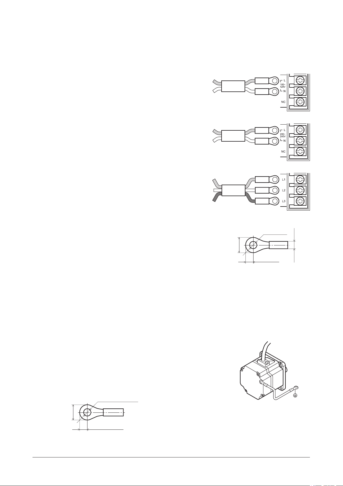
7.2 Connecting the power supply
Connect the power cable to the Power supply input terminal (TB1) on the driver.
Tightening torque: 1.0 N·m (8.8 lb-in)
The product does not come with a power cable. It must be supplied by the user.
Single-phase 100-120 V
z
Connect the live side to terminal L, and the neutral side to
terminal N.
Single-phase 200-240 V
z
Connect the live side to terminal L, and the neutral side to
terminal N.
Three-phase 200-240 V
z
Connect the R, S and T phase lines to the L1, L2 and L3
terminals, respectively.
L
N
L
N
R
S
Power connection terminal and cable
z
•Applicable crimp terminal: Round crimp terminal with insulation cover
•Thread size of terminal: M3.5
•Applicable lead wire: AWG18 to 14 (0.75 to 2.0 mm
•Temperature rating of lead wire: 60 °C, 60 or 75 °C, or 75 °C
(140 °F, 140 or 167 °F, or 167 °F)
•Conductive material: Use only copper wire.
Circuit breaker
Be sure to connect a circuit breaker to the power line of the driver to protect the primary circuit.
Rated current of protective device: Single-phase input 10 A, three-phase input 5 A
Circuit breaker: Mitsubishi Electric Corporation NF30
7.3 Grounding
Grounding the motor
Connect the Protective Earth Terminal on the motor to the ground near the
motor. Minimize the wiring length of the ground cable.
Tightening torque: 0.8 to 1.0 N·m (7.0 to 8.8 lb-in)
Ground terminal and cable
z
•Applicable crimp terminal: Round crimp terminal with insulation cover
•Thread size of terminal: M4
•Applicable lead wire: AWG18 to 14 (0.75 to 2.0 mm
T
Ø3.6 (0.14)
2
)
7.2 (0.28) or less
2
)
or more
3.8 (0.15)
or less
6.2 (0.24) or less
Unit: mm (in.)
after crimping
−26−
Ø4.1 (0.16) or more
9.5 (0.37) or less
4.8 (0.19) or less
Unit: mm (in.)
Page 27

Grounding the driver
(Ground one of these terminals.)
Be sure to ground the Protective Earth Terminal (screw size: M4) of the driver.
Tightening torque: 1.2 N·m (10.6 lb-in)
You can ground either of the two Protective Earth Terminals. The terminal that
is not grounded is used as a service terminal. Use the service terminal according
to your specic need, such as connecting it to the motor in order to ground the
motor.
Use a grounding wire of AWG18 to 14 (0.75 to 2.0 mm
Protective Earth Terminal with a welder or any other power equipment.
When grounding the Protective Earth Terminal, use a round terminal and afx the grounding point near the driver.
7.4 Connecting the motor and driver
Connect the motor cable to the motor connector (CN2) and motor signal connector (CN4) of the driver.
Insert the motor power connector into CN2, and the motor signal connector into CN4.
For the electromagnetic brake type, connect the connector for the electromagnetic brake to the CN1.
To expand connection between the motor and driver, use the connection cable (supplied or accessory).
Connection can be extended to a maximum of 20.4 m (66.9 ft.).
2
), and do not share the
Motor signal connector:
Connect to CN4
Connection
Protective Earth Terminal
Motor cable
Connection cable
Electromagnetic brake connector:
Connect to CN1
Motor power connector:
Connect to CN2
∗
Electromagnetic brake type only
*
Note Have the connector plugged in securely. Insecure connector connection may cause malfunction or
damage to the motor or driver.
Connector of the motor cable
Motor power connector
z
Pin No. Color Lead wire Pin No. Color Lead wire
1 Blue AWG18 1 − −
2 − − 2 Green AWG26
3 −
4 Purple AWG18 6 Orange AWG26
5 Gray AWG18
6 − −
Drain
AWG24 or
equivalent
6
3
5
2
4
1
Housing:
5557-06R-210
(Molex)
Terminal:
5556T (Molex)
Motor signal connector
z
3 Yellow AWG26
4 Brown AWG26
5 Red AWG26
6
3
5
2
4
1
Housing:
43025-0600
(Molex)
Terminal:
43030-0004
(Molex)
Connector of the electromagnetic brake
Pin No. Color Lead wire
1 Black AWG24
2 White AWG24
21
Housing:
5557-02R-210
(Molex)
Terminal:
5556T (Molex)
−27−
Page 28

Connection
Connection cable
This cable (sold separately) is used to extend the wiring distance between the driver and motor. Flexible connection
cables are also available. You can connect up to three connection cables.
•Standard type
Connection cable
Length
[m (ft.)]
1 (3.3)
2 (6.6)
3 (9.8)
5 (16.4)
7 (23.0)
10 (32.8)
15 (49.2)
20 (65.6)
CC01BLE
CC02BLE
CC03BLE
CC05BLE
CC07BLE
CC10BLE
CC15BLE
CC20BLE
Model
•Standard type
Flexible connection cable
Length
[m (ft.)]
1 (3.3)
2 (6.6)
3 (9.8)
5 (16.4)
7 (23.0)
10 (32.8)
15 (49.2)
20 (65.6)
Model
CC01BLER
CC02BLER
CC03BLER
CC05BLER
CC07BLER
CC10BLER
CC15BLER
CC20BLER
•Electromagnetic brake type
Connection cable
Length
[m (ft.)]
1 (3.3)
2 (6.6)
3 (9.8)
5 (16.4)
7 (23.0)
10 (32.8)
15 (49.2)
20 (65.6)
7.5 Connecting the regeneration unit
Use the accessory regeneration unit
EPRC-400P
stopping of a large inertia load, will be repeated frequently.
Install the regeneration unit in a location where heat dissipation capacity equivalent to a level achieved with a heat
sink [made of aluminum, 350×350×3 mm (13.78×13.78×0.12 in.)] is ensured.
Connection method
z
Connection to the I/O terminals varies depending on the connection method. Refer to p.35.
Connect the regeneration unit before turning on the main power. The regeneration unit does not perform its control
function if connected after the main power has been turned on.
•Regenerative current ows through the two thick lead wires (AWG18: 0.75 mm
them to the RG1 and RG2 terminals of the TB1. The applicable crimp terminal is the same as the one used to
connect the power supply. Refer to p.26.
•The two thin lead wires (AWG22: 0.3 mm
connection method.
(sold separately) if gravitational operation or sudden starting/
2
) of the regeneration unit are thermostat outputs. Refer to p.29 for the
Model
CC01BLEM
CC02BLEM
CC03BLEM
CC05BLEM
CC07BLEM
CC10BLEM
CC15BLEM
CC20BLEM
•Electromagnetic brake type
Flexible connection cable
Length
[m (ft.)]
1 (3.3)
2 (6.6)
3 (9.8)
5 (16.4)
7 (23.0)
10 (32.8)
15 (49.2)
20 (65.6)
2
) of the regeneration unit. Connect
Model
CC01BLEMR
CC02BLEMR
CC03BLEMR
CC05BLEMR
CC07BLEMR
CC10BLEMR
CC15BLEMR
CC20BLEMR
(302 °F)
EPRC-400P
AWG22
AWG18
To RG1 and RG2 terminals on TB1
Connect
to CN5
P.35 to 37
Regeneration unit
R: 400 Ω
150 °C [N.C.]
Note •If the current consumption of the regeneration unit exceeds the allowable level, the thermostat
will be triggered and a regeneration unit overheat alarm will generate. If a regeneration unit
overheat alarm generates, turn off the power and check the content of the error.
•When an external power supply is used for the power supply for input signals, turn on the
external power supply before supplying the AC power to the driver.
Regeneration unit specications
z
Model
Continuous regenerative power 100 W
Resistance 400
Operating temperature of
thermostat
Electrical rating of thermostat 120 VAC 4 A, 30 VDC 4 A (minimum current: 5 mA)
EPRC-400P
Ω
Operation: Opens at 150±7 °C (302±45 °F)
Reset: Closes at 145±12 °C (293±54 °F) (normally closed)
−28−
Page 29

7.6 Selecting the I/O signal power supply
Select the I/O signal power supply (built-in
power supply or external power supply) to be
used.
The driver comes with a built-in power supply.
To control the operation using relays and
External voltage selection switch
SW2-1
switches, set the external voltage selector
switch SW2-1 to the ON side to select the
built-in power supply.
Factory setting:
OFF (an external power supply is used)
Note •Change the setting of the external voltage selector switch SW2-1 before turning on the power.
•The built-in power supply cannot be used with the source logic. If the source logic is used, do
not turn the external voltage selector switch to the ON position.
7.7 Connecting the I/O signals
Connector function table
Pin No.
1 C0 IN-COM0 Input signal common −
2 X0
3 X1
4 X2
5 X3
6 X4
7 X5
8 X6
9 VH VH
10 VM VM
11 VL VL
12 C1 IN-COM1 Input common (0 V) −
13 Y0+
14 Y0−
15 Y1+
16 Y1−
Terminal
name
*
*
*
*
*
*
*
*
*
*
*
Signal name Name Explanation
FWD Forward input The motor turns in the clockwise direction.
REV Reverse input The motor turns in the counterclockwise direction.
STOP-MODE
M0
ALARM-RESET Alarm reset input Alarms are reset.
MB-FREE
TH
SPEED-OUT (+)
SPEED-OUT (−)
ALARM-OUT1 (+)
ALARM-OUT1 (−)
*
Stop mode selection
input
Speed setting selection
input
Electromagnetic brake
release input
Regeneration resistor
thermal input
External speed setting
input
SPEED-OUT output
ALARM-OUT1 output
The
OPX-2A
or
MEXE02
Select instantaneous stop or deceleration stop.
Select the internal potentiometer or external
potentiometer (external DC voltage).
Select the operation mode of the electromagnetic
brake when the motor stops. This signal is not
used for the standard type.
If a regeneration unit is used, connect the
thermostat output of the regeneration unit (normally
closed).
Set the speed of the external potentiometer
(external DC voltage). Refer to p.39 for details.
30 pulses are output with each revolution of the
motor output shaft. (To use this signal in the
compatible mode, refer to p.44.)
This signal is output when an alarm generates
(normally closed).
can be used to change the assignments of I/O signals. Refer to p.47.
Connection
ON: Using the built-in
power supply
OFF: Using an external
power supply
FBL
Ⅱ
−29−
Page 30

Connection
Connecting input/output signals
The combination type connector is used for the input/output signal
connection (CN5).
The combination connector may be installed and removed with the lead
wire connected, thereby offering better work efciency for driver
installation and maintenance.
1.
Strip the lead wire and twist the cable conductor.
Applicable lead wire diameter:
AWG24 to 20 (0.2 to 0.5 mm
2
)
Length of the lead wire which can be peeled:
4 mm (0.16 in.)
2.
Loosen the combination connector screw.
3.
Insert the stripped cable conductor into the combination
connector, and tighten the screw.
Use a 2 to 2.5 mm (0.079 to 0.098 in.) wide slotted head
screwdriver.
Tightening torque: 0.22 to 0.25 N·m (1.94 to 2.2 lb-in)
If crimp terminals are used, select the following terminals.
Combination
connector
CN5
4 mm
(0.16 in.)
Manufacturer PHOENIX CONTACT GmbH & Co. KG
AI 0.25-6 [AWG24 (0.2 mm
Model
Input signal circuit
AI 0.34-6 [AWG22 (0.3 mm
AI 0.5-6 [AWG20 (0.5 mm
All input signals of the driver are photocoupler
inputs.
When an external power supply is used:
24 VDC –15 to +20%, 100 mA or more
Output signal circuit
The driver outputs signals are photocoupler/open-collector output.
The ON voltage of the output circuit is max. 1.6 V. When driving each
element using the output signal circuit, give consideration to this ON
voltage.
2
)]
2
)]
2
)]
Pin No.
1
2 to 8
12
External voltage
selection switch SW2-1
5.1 kΩ
1.8 kΩ
Pin No.
13, 15
14, 16
Photo-coupler of
reinforced insulation
4.5 to 30 VDC, 40 mA or less
(For the SPEED-OUT output, supply at least 5 mA of current.)
Note •Always connect a current-limiting resistor. If the power supply voltage is connected to the
output circuit directly without connecting a current-limiting resistor in between, the driver will be
damaged.
•When connecting a relay (inductive load), etc., to detect
alarm outputs, use a relay with built-in ywheel diode, or
provide a y-back voltage control measure based on diode,
Inductive load
etc., for the inductive load.
Pin No.
13, 15
+17 V
0 V
Flywheel
diode
−30−
Page 31

Connection
Stop
Input signals
The signal state represents the “ON: Carrying current” or “OFF: Not carrying current” state of the internal
photocoupler rather than the voltage level of the signal.
FWD input and REV input
z
When the FWD input is turned ON, the motor turns in the clockwise direction according to the time set by the
acceleration time potentiometer. When the FWD input is turned OFF, the motor stops.
When the REV input is turned ON, the motor turns in the counterclockwise direction according to the time set by the
acceleration time potentiometer. When the REV input is turned OFF, the motor stops.
If both the FWD input and REV input are turned ON, the motor stops instantaneously.
STOP-MODE input
z
Select how the motor should stop when the FWD input or REV input is turned OFF.
When the STOP-MODE input is ON, the motor stops according to the time set by the deceleration time potentiometer.
STOP-MODE input is OFF, the motor stops instantaneously.
M0 input
z
Select how the motor speed is set.
When the M0 input is ON, the motor turns at the speed set by the external potentiometer or external DC voltage.
When the M0 input is OFF, the motor turns at the speed set by the internal potentiometer.
By switching the M0 input, the motor can be operated at two speeds through use of both the external potentiometer
and internal potentiometer. Refer to p.42 for details.
You can set a maximum of eight speeds by changing the assignments of M0 to M2 inputs using the
MEXE02
.
OPX-2A
or
ALARM-RESET input
z
This input actuates the driver’s protective function to reset present alarms.
To reset each alarm, be sure to remove the cause of the alarm before switching the ALARM-RESET input.
To reset an alarm, turn both the FWD input and REV input OFF, remove the cause of the alarm, and then turn the
ALARM-RESET input ON (and keep it ON for 10 ms or more). The ALARM-RESET input will not be received if
the FWD input or REV input is ON.
If the alarm cannot be reset with the ALARM-RESET input, turn off the power, wait for at least 30 seconds, and then
turn the power back on.
Motor operation pattern
Electromagnetic brake operation
ALARM-RESET input
ALARM-OUT1 input
The electromagnetic brake locks the moment an alarm generates. The electromagnetic brake can be set to lock after a free-
*
run stop of the motor using the
FWD input
OFF
OFF
OFF
CW CW
∗
Release
ON
ON
ON
OPX-2A
10 ms or more 10 ms or more
or
MEXE02
Lock
.
Release
10 ms or less
Note •Continuing the operation of the unit without removing the cause of the alarm may result in
equipment damage.
•Overcurrent and EEPROM errors cannot be reset using the ALARM-RESET input.
MB-FREE input
z
This input signal is used for the electromagnetic brake type. The operation mode of the electromagnetic brake at
motor standstill is selected.
When the MB-FREE input is ON, the electromagnetic brake will be released.
When the MB-FREE input is OFF, the electromagnetic brake will actuate and hold the shaft in position.
Note The MB-FREE input is disabled while an alarm is present.
TH input
z
When using the regeneration unit
EPRC-400P
, connect the thermostat output of the regeneration unit (normally
closed).
−31−
Page 32

Connection
Stop
Output signals
The signal state represents the “ON: Carrying current” or “OFF: Not carrying current” state of the internal
photocoupler rather than the voltage level of the signal.
SPEED-OUT output
z
30 pulses are output with each revolution of the motor output shaft synchronously with the motor operation.
The pulse width of output pulse signals is 0.2 ms. You can use the SPEED-OUT output to calculate the motor speed.
SPEED-OUT output frequency (Hz) =
Motor shaft speed (r/min) =
SPEED-OUT output frequency
1
T
30
× 60
T
0.2 ms
To display/monitor the speed of the motor output shaft or reduced speed of the gearhead output shaft, connect the
accessory digital speed indicator
ALARM-OUT1 output
z
SDM496
(sold separately). Refer to p.51 for details.
When the driver’s protective function actuates, the ALARM-OUT1 output turns OFF and the ALARM LED blinks
(normally closed).
The motor coasts to a stop in the case of a standard type. When the motor is an electromagnetic brake type, the motor
stops instantaneously and the electromagnetic brake is actuated to hold the shaft in position.
To reset an alarm, turn both the FWD input and REV input OFF, remove the cause of the alarm, and then turn the
ALARM-RESET input ON (and keep it ON for 10 ms or more). The ALARM-RESET input will not be received if
the FWD input or REV input is ON.
If the alarm cannot be reset with the ALARM-RESET input, turn off the power, wait for at least 30 seconds, and then
turn the power back on.
Motor operation pattern
Electromagnetic brake operation
FWD input
ALARM-RESET input
ALARM-OUT1 input
OFF
OFF
OFF
CW CW
ON
ON
ON
∗
Release
10 ms or more 10 ms or more
Lock
Release
10 ms or less
The electromagnetic brake locks the moment an alarm generates. The electromagnetic brake can be set to lock after a free-
*
run stop of the motor using the
Using a controller with a built-in clamp diode
OPX-2A
If a controller with a built-in clamp diode is used, a leakage
path may form and cause the motor to operate even when the
controller power is off, as long as the driver power is on. Since
the power capacity of the controller is different from that of the
or
MEXE02
.
External control
equipment
VCC +17 V
Driver
driver, the motor may operate when the controller and driver
powers are turned on or off simultaneously.
When powering down, turn off the driver power rst, followed
by the controller power.
When powering up, turn on the controller power rst, followed
by the driver power.
0 V
2 to 8
12
0 V
−32−
Page 33

Example of connection with I/O signal circuit
Sink logic circuit
z
Programmable controller Driver
24 VDC
1
5.1 kΩ
2
Connection
1.8 kΩ
5.1 kΩ
3
5.1 kΩ
4
5.1 kΩ
5
5.1 kΩ
6
0 V
30 VDC or less
R
0
40 mA or less
R0
40 mA or less
0 V
Source logic circuit
z
13
14
15
16
5.1 kΩ
7
5.1 kΩ
8
1.8 kΩ
1.8 kΩ
1.8 kΩ
1.8 kΩ
1.8 kΩ
1.8 kΩ
Programmable controller Driver
24 VDC
1
13
14
15
16
5.1 kΩ
2
5.1 kΩ
3
5.1 kΩ
4
5.1 kΩ
5
5.1 kΩ
6
5.1 kΩ
7
5.1 kΩ
8
0 V
30 VDC or less
0 V
40 mA or less
R
0
40 mA or less
R0
1.8 kΩ
1.8 kΩ
1.8 kΩ
1.8 kΩ
1.8 kΩ
1.8 kΩ
1.8 kΩ
Note •Keep the output signal to 30 VDC or less.
•Be sure to connect the current-limiting resistor R
0
and keep the current to 40 mA or less.
−33−
Page 34

Connection
7.8 Connecting the communication cable
Connect
OPX-2A
cable or support software communication cable (accessory) to the communication connector (CN3).
OPX-2A cable or support software communication cable
−34−
Page 35

7.9 Connection diagram (example)
power supply
or
brake connector
OWER
G1RG2
t
Each connection diagram (example) is for the electromagnetic brake type. In the case of the standard type, there are
no connection for the electromagnetic brake and no connection/input for the MB-FREE input signal.
To use the built-in power supply, set the external voltage selector switch
(SW2-1) to the ON side.
The factory setting is OFF (an external power supply is used).
To use an external power supply, the factory setting need not be changed.
Note Change the setting of the external voltage selector switch (SW2-1) before turning on the main
power supply.
Sink logic
Using the built-in power supply
z
In the connection example given below, the motor is operated with a single-phase 100 to 120 V power supply, relays,
switches and other contact switches. For the SPEED-OUT output, supply at least 5 mA of current.
Driver
Connection
ON: Using the built-in
power supply
OFF: Using an external
Power supply connection
Driver ground
Regeneration unit connection
R:400 Ω
N.C.
150 °C
(302 °F)
External potentiometer
(20 kΩ 1/4 W)
Not to exceed the voltage
selected by the external
voltage selection switch
Communication cable
connection
Circuit breaker
L
N
VH
VM
VL
IN-COM0
FWD
REV
STOP-MODE
M0
ALARM-RESET
MB-FREE
P
Main circui
Motor cable
connection
Motor connect
Motor
R
Electromagnetic
Motor ground
Control circuit
10
11
+5.3 V
9
Speed
command
voltage
0 V
Motor signal
connector
Output signal connection
4.5 to 30.0 VDC
40 mA or less
13
14
+17 V
1
5.1 kΩ
2
3
4
5
6
7
15
16
SPEED-OUT
∗
∗
ALARM-OUT1
∗Recommended resistance
24 VDC:
680 Ω to 4.7 kΩ (2 W)
5 VDC:
150 Ω to 1.0 kΩ (0.5 W)
IN-COM1
TH
12
8
0 V
Shielded cable
Functional grounding
−35−
Page 36

Connection
R
G1RG2
a
t
or
brake connector
Using an external power supply
z
In the connection example given below, the motor is operated with a single-phase 100 to 120 V power supply based
on transistor sequence connection. For the SPEED-OUT output, supply at least 5 mA of current.
Driver
Power supply connection
Regeneration unit connection
R:400 Ω
N.C.
150 °C
(302 °F)
External potentiometer
(20 kΩ 1/4 W)
Not to exceed the voltage
selected by the external
voltage selection switch
Communication cable
connection
Input signal connection∗1
20.4 to 28.8 VDC
100 mA or more
Circuit breaker
L
N
Driver ground
IN-COM0
FWD
REV
STOP-MODE
ALARM-RESET
MB-FREE
VH
VM
VL
M0
POWE
R
9
10
11
1
2
3
4
5
6
7
M
Control circuit
+5.3 V
Speed
command
voltage
0 V
5.1 kΩ
in circui
Motor connect
Electromagnetic
Motor signal
connector
13
14
15
16
Motor cable
connection
Motor
Motor ground
Output signal
connection
4.5 to 30.0 VDC
40 mA or less
SPEED-OUT
∗2
∗2
ALARM-OUT1
∗2 Recommended resistance
24 VDC:
680 Ω to 4.7 kΩ (2 W)
5 VDC:
150 Ω to 1.0 kΩ (0.5 W)
TH
8
IN-COM1
Turn ON the external power supply before turning ON the main power supply of the driver.
*1
12
0 V
−36−
Shielded
cable
Functional
grounding
Page 37

Connection
or
c
brake connector
OWER
G1RG2
t
Source logic
In the connection example given below, the motor is operated with a single-phase 200 to 240 V power supply based
on transistor sequence connection. For the SPEED-OUT output, supply at least 5 mA of current.
Driver
Circuit breaker
Power supply
connection
L
N
Driver ground
Regeneration unit connection
R:400 Ω
N.C.
150 °C
( 302°F)
External potentiometer
(20 kΩ 1/4 W)
Not to exceed the voltage
selected by the external
voltage selection switch
Communication cable
connection
Input signal connection∗1
20.4 to 28.8 VDC
100 mA or more
STOP-MODE
ALARM-RESET
VH
VM
VL
FWD
REV
M0
MB-FREE
P
Main circui
Motor cable
connection
Motor connect
Motor
Electromagneti
R
Motor ground
Control circuit
10
11
+5.3 V
9
Speed
command
voltage
0 V
Motor signal
connector
Output signal connection
4.5 to 30.0 VDC
40 mA or less
13
14
15
16
5.1 kΩ
2
3
4
5
6
7
SPEED-OUT
∗2
∗2
ALARM-OUT1
∗2 Recommended resistance
24 VDC:
680 Ω to 4.7 kΩ (2 W)
5 VDC:
150 Ω to 1.0 kΩ (0.5 W)
IN-COM0
IN-COM1
Turn ON the external power supply before turning ON the main power supply of the driver.
*1
TH
1
8
12
0 V
Shielded cable
Functional
grounding
−37−
Page 38

Operation
8 Operation
This chapter explains the operations that can be performed with the
8.1 Operation overview
With the
compatible mode, and extended operations using the
each operation and the reference pages.
operation
Basic operation
Operations in
FBL
Ⅱ
mode
Extended
operations using
the
MEXE02
Series, you can perform three types of operations including basic operations, operations in the
BLE
Type of
Speed
setting
Run/stop Run/stop the motor. P.40
Setting the acceleration time
and deceleration time
Changing the speed
Examples of operation patterns
Parallel operation
Settings of the following items can be changed in the same manner as with the
FBL
Ⅱ
•Operation that should take place when the FWD input and REV input turn ON
simultaneously
compatible
OPX-2A
•Operation that should take place when the direction is switched instantaneously
•SPEED-OUT output setting
•Alarm output logic
•Speed setting range
•Acceleration/deceleration time settings
•The following functions are extended when the
Refer to p.47 for the assignments of I/O signals as well as operation patterns
when eight speeds are set:
•Operating speed (maximum of 8 speeds)
•Torque limit
•Change of I/O signal assignments
or
•Various displays (speed, alarm code, load factor)
•I/O monitor
•Warning output
•Test operation
•Data copy
Series.
BLE
FBL
OPX-2A
What you can do Explanation Ref.
Internal
potentiometer
External
potentiometer
External DC
voltage
Series:
or
MEXE02
Set the speed using the internal potentiometer.
The operating method, stopping method and
direction switching method are also explained
here.
Set the speed using the external potentiometer.
Set the speed using external DC voltage.
You can set the acceleration time and
deceleration time separately for starting and
stopping.
Operation can be performed at two speeds
through use of both the external potentiometer
(external DC voltage) and internal
potentiometer.
Examples of run/stop are explained using
timing charts.
A single external potentiometer (external DC
voltage) can be used to set the same speed
for multiple motors.
. The table below shows the details of
OPX-2A
or
MEXE02
is used.
P.39
P.41
P.42
P.42
P.43
P.44
P.47
Ⅱ
−38−
Page 39

8.2 Basic operation
External potentiometer [position]
External DC voltage [V]
Speed setting
The setting range is 100 to 4000 r/min.
Setting by internal potentiometer
z
Use a precision screwdriver to turn the internal potentiometer.
Turn the potentiometer clockwise to increase the speed.
Factory setting: 0 r/min
Setting by the external potentiometer
z
Connect the supplied external potentiometer to the I/O signal connector (CN5) of the driver.
Use the supplied signal wire [1 m (3.3 ft.)] for this connection.
Ground the shielded wire of the signal wire. Make sure the shielded
wire does not contact other terminals.
When the M0 input is turned ON, the external potentiometer is
enabled. Turn the potentiometer clockwise to increase the speed.
CN5
10
11
9
VH input
VM input
VL input
Red
White
Yellow
External potentiometer
Low
speed
Yellow
White
Red
1 2 3
High
speed
Operation
Slow
Fast
•External potentiometer position vs. speed
characteristics (representative values)
4000
3500
3000
2500
2000
1500
1000
Motor shaft speed [r/min]
500
0 20 40 60 80 100
Setting with external DC voltage
z
Refer to p.45 for the characteristics when the
*
compatible mode is used.
FBL
Ⅱ
Set either 5 or 10 VDC for the external DC voltage. Use
the external voltage selector switch SW2-2 to set which
voltage to be used. 5 VDC is set when the switch is set
to the ON position, and 10 VDC is set when the switch
External voltage selection switch
SW2-2
is set to the OFF position.
Factory setting: 5 VDC (ON)
ON: 5 VDC
OFF: 10 VDC
Note Change the setting of the external voltage selector switch SW2-2 before turning on the power.
For the external voltage, use a DC power supply (0 to 5 VDC or 0 to 10 VDC) with reinforced insulation on both
the primary side and secondary side, and use the supplied signal wire [1 m (3.3 ft.)] to connect it to the I/O signal
connector (CN5).
Ground the shielded wire of the signal wire. Make sure the
shielded wire does not contact other terminals.
The input impedance between the VM input and VL input is
approx. 15 kΩ when SW2-2 is ON, and approx. 30 kΩ when
OFF. The VL input is connected to IN-COM1 inside the driver.
CN5
10
11
VM input
VL input
White
Yellow
White
Yellow
External DC
power supply
0 to 5 VDC
1 mA or more
•External DC voltage vs. speed characteristics
(representative values)
4000
3500
3000
2500
2000
1500
1000
Motor shaft speed [r/min]
500
5 VDC
10 VDC
Note Be sure to set the external DC voltage to either 5 VDC or less, or 10 VDC or less. When
2 4 6 81 3 5 7 109
0
Refer to p.45 for the characteristics when the
*
compatible mode is used.
FBL
Ⅱ
connecting the external DC power supply, make sure the polarities are correct. If the polarities are
reversed, the driver may be damaged.
−39−
Page 40

Operation
Deceleration
Instantaneous
FWD input is ON
Running/stopping the motor
Run/stop the motor by inputting operation control signals.
Operation
z
When the FWD input is turned ON, the motor turns in the clockwise direction according to the time set by the
acceleration time potentiometer. When the FWD input is turned OFF, the motor stops.
When the REV input is turned ON, the motor turns in the counterclockwise direction according to the time set by the
acceleration time potentiometer. When the REV input is turned OFF, the motor stops.
If the FWD input and REV input are turned ON at the same time, the motor stops instantaneously.
stop
Motor operation
Electromagnetic brake operation
FWD input
REV input
STOP-MODE input
ON
OFF
ON
OFF
ON
OFF
Release
Release
stop
Note When using the motor in vertical drive (gravitational operation), although it depends on the load
condition, if operation is performed with the setting below, the motor shaft may momentarily
rotate in the reverse direction (about one-fourth revolution of the motor output shaft) at the time of
starting/stopping the motor.
· When the set rotation speed is low
· When the acceleration time and deceleration time is long
Stop
z
Select how the motor should stop when the FWD input or REV input is turned ON.
When the STOP-MODE input is ON, the motor stops according to the time set by the deceleration time potentiometer.
STOP-MODE input is OFF, the motor stops instantaneously.
FWD input REV input STOP-MODE input Motor status
ON OFF − Clockwise rotation
OFF ON − Counterclockwise rotation
ON ON − Instantaneous stop
− − OFF Instantaneous stop
− − ON Deceleration stop
Rotating direction of the motor output shaft
The rotating direction of the motor output shaft represents the direction when viewed from the motor output shaft side.
Combination type parallel shaft gearhead
z
The rotating direction of the motor output shaft may vary
from that of the gearhead output shaft depending on the gear
ratio of the gearhead.
Gear ratio
5, 10, 15, 20, 200 Same as the motor output shaft
30, 50, 100 Opposite to the motor output shaft
Rotating direction of gearhead
output shaft
When the
REV input
is ON
When the
−40−
Page 41

Operation
Combination type hollow shaft at gearhead
z
For all gear ratios, the output shaft turns in the opposite direction to the motor as viewed from the front of the
gearhead. The direction is different depending on whether the motor/gearhead assembly is viewed from the front side
or rear side.
• Viewed from Front • Viewed from Rear
When the FWD
input is ON
When the REV
input is ON
When the REV
input is ON
When the FWD
input is ON
8.3 Setting the acceleration time and deceleration time
You can set the acceleration time and deceleration time separately for starting and stopping.
The acceleration time and deceleration time are effective for all speed settings.
Sudden start
Gradual start
Sudden stop
Gradual stop
Setting the acceleration time
“Acceleration time” refers to the time needed to reach the rated speed (3000 r/min).
Set the acceleration time using the acceleration time potentiometer (ACCEL). Turning the potentiometer clockwise
increases the time.
The setting range is 0.2 to 15 sec.
Factory setting: 0.2 sec
Setting the deceleration time
“Deceleration time” refers to the time needed for the motor to stop from the rated speed (3000 r/min).
Set the deceleration time using the deceleration time potentiometer (DECEL). Turning the potentiometer clockwise
increases the time.
The setting range is 0.2 to 15 sec.
Factory setting: 0.2 sec
3000 r/min
t1 t2
t1, t2 = 0.2 to 15 sec (3000 r/min)
“Acceleration time (t1)” refers to the time needed for the motor to reach the rated speed (3000 r/min) from the
stationary state.
“Deceleration time (t2)” refers to the time needed for the motor to stop from the rated speed (3000 r/min).
The actual acceleration time and deceleration time vary depending on the conditions of use, load inertia, load torque,
etc. If smooth acceleration operation or deceleration operation is not possible, increase the acceleration time or
deceleration time.
−41−
Page 42

Operation
8.4 Changing the speed
Operation can be performed at two speeds through use of both the internal potentiometer and external potentiometer
(external DC voltage).
When the M0 input is ON, the motor turns at the speed set by the external potentiometer or external DC voltage.
When the M0 input is OFF, the motor turns at the speed set by the internal potentiometer.
FWD input
REV input
STOP-MODE input
M0 input
Clockwise
Motor operation
Counterclockwise
ON
OFF
ON
OFF
ON
OFF
ON
OFF
potentiometer
Internal
External potentiometer
Deceleration stop
Internal
potentiometer
Instantaneous stop
Electromagnetic brake operation
Release
8.5 Examples of operation patterns
The charts below are examples of setting the internal potentiometer to 3000 r/min and external potentiometer to
1000 r/min and switching the speed between these two levels.
Operating/
Clockwise
Motor operation
Counterclockwise
FWD input
(Clockwise)
REV input
(Counterclockwise)
STOP-MODE input
(Deceleration stop/
Instantaneous stop)
M0 input
(Internal potentiometer/
External potentiometer)
Electromagnetic
brake operation
Release
Speed switching/
Stopped
3000 r/min
1000 r/min
ON
OFF
ON
OFF
ON
OFF
ON
OFF
Lock
Operating/
Instantaneous stop
External potentiometer
Release
Direction switching/
instantaneous reversion
Acceleration operation/
Deceleration stop/
Instantaneous stop
during deceleration
−42−
Note •Make sure each signal remains ON for at least 10 ms.
•When switching the FWD input and REV input, provide an interval of at least 10 ms.
Page 43

Operation
OFF
Power input Power line
If the FWD input and REV input are turned ON at the same time, the motor stops instantaneously regardless of the
status of the STOP-MODE input.
Motor operation
FWD input
REV input
STOP-MODE input
ON
OFF
ON
OFF
ON
8.6 Parallel operation
If two or more motors are to be operated at the same speed by using a single external potentiometer (external DC
voltage), this type of operation is called “parallel operation.”
Parallel operation is achieved by allowing multiple drivers to share the power line and speed setting line.
•The connection examples explained here assume a single-phase specication. In the case of a three-phase
specication, connect the power line to a three-phase power supply.
•Connect the external I/O signals to each driver.
•To perform parallel operation using the external potentiometer, set the external voltage selector switch (SW2-2) to
5 VDC.
•Set the external voltage selector switch (SW2-2) the same way for all the drivers.
Using an external potentiometer
Connect the drivers as shown below.
When performing parallel operation using the external potentiometer, the number of drivers should not exceed
20 units.
CW CW
Instantaneous
stop
Deceleration
stop
2
13
External potentiometer
VRx
Driver 1 Driver n
VH
470 Ω, 1/4 W
VM
VL
L
N
L
N
VH
VM
VRn
1 kΩ, 1/4 W
VL
Speed setting line
If the number of drivers used is “n,” calculate resistance (VRx) of the external potentiometer using the formula below:
Resistance (VRx) = 20/n (kΩ), n/4 (W)
Example: If two drivers are used, resistance (VRx) is calculated as 10 kΩ, 1/2 W [20/2 (kΩ), 2/4 (W)].
(Use a resistor of the calculated wattage or more.)
If the speed will vary among the respective motors, make adjustments by connecting a resistor of 470 Ω, 1/4 W to
terminal VM on driver 1 and connecting a variable resistor of 1 kΩ, 1/4 W to driver 2 and subsequent drivers.
−43−
Page 44
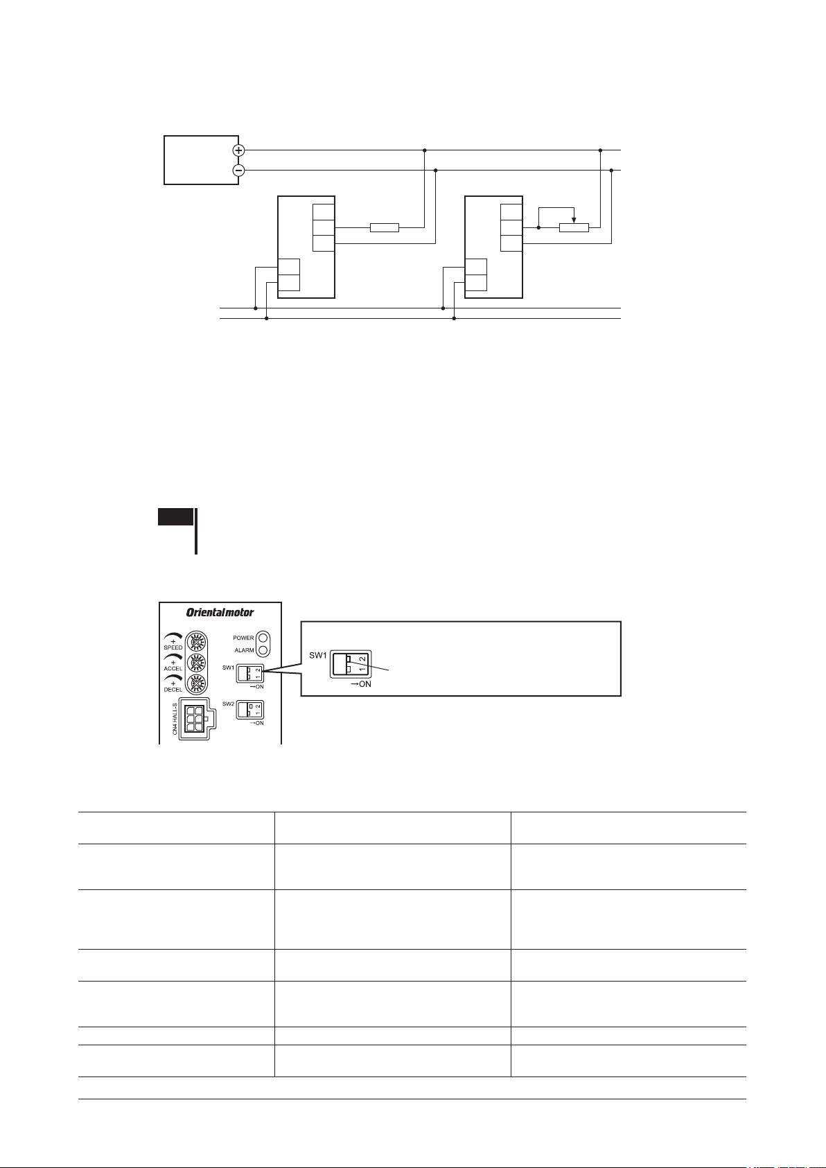
Operation
Power input Power line
Using external DC voltage
Connect the drivers as shown below.
DC power supply
0 to 5 VDC
or
0 to 10 VDC
Driver 1 Driver n
VH
VM
VL
470 Ω, 1/4 W
Speed setting line
VRn
1 kΩ, 1/4 W
VH
VM
VL
L
N
L
N
If the number of drivers used is “n,” calculate the current capacity (I) of the external DC power supply using the
formula below:
Current capacity (I) = 1 × n (mA)
Example: If two drivers are used, current capacity (I) is calculated as 2 mA or more [1 × 2 (mA)].
If the speed will vary among the respective motors, make adjustments by connecting a resistor of 470 Ω, 1/4 W to
terminal VM on driver 1 and connecting a variable resistor of 1 kΩ, 1/4 W to driver 2 and subsequent drivers.
8.7 Setting the FBLⅡcompatible mode and operation
In this mode, the settings switch to those identical to the
Switch the mode using the
Note Change the setting of the
compatible mode setting switch (SW1-2).
FBL
Ⅱ
FBL
compatible mode setting switch (SW1-2) before turning on the
Ⅱ
main power supply. If the switch setting is changed after the main power supply has been turned
on, the new setting does not become effective.
ON: The
OFF: The
compatible mode is enabled.
FBL
Ⅱ
compatible mode is disabled (factory setting).
FBL
Ⅱ
FBLⅡcompatible mode setting switch (SW1-2)
FBL
Ⅱ
Series.
Details of FBL
compatible mode
Ⅱ
ON: The FBLⅡcompatible mode is enabled.
OFF: The FBLⅡcompatible mode is disabled.
The acceleration time and deceleration time vary depending on load.
Item
Operation that should take place
when the FWD input and REV
input turn ON simultaneously
Operation that should take place
when the direction is switched
instantaneously
SPEED-OUT output setting
Alarm output logic
Speed setting range 300 to 3000 r/min 100 to 4000 r/min
Acceleration and deceleration time
setting
The FWD input is given priority and the
motor turns in the clockwise direction.
The motor stops instantaneously and the
direction also switches instantaneously.
12 pulses are output with each motor
revolution (pulse width: 0.5 ms).
The alarm output turns ON when the
driver’s protective function triggers
(normally open).
Setting range: 0.5 to 15 sec (at 3000 r/min) Setting range: 0.2 to 15 sec (at 3000 r/min)
FBL
compatible mode
Ⅱ
FBL
(The
The motor stops instantaneously.
The motor stops instantaneously and
the direction switches according to the
acceleration time set by the acceleration
time potentiometer (ACCEL).
30 pulses are output with each motor
revolution (pulse width: 0.2 ms).
The alarm output turns OFF when the
driver’s protective function triggers and an
alarm generates (normally closed).
compatible mode is disabled)
Ⅱ
BLE
Series
−44−
Page 45

Operation
Control of operation in FBL
FWD input REV input STOP-MODE input Motor status
ON OFF − Clockwise rotation
OFF ON − Counterclockwise rotation
ON ON − Clockwise rotation
− − OFF Instantaneous stop
− − ON Deceleration stop
Speed characteristics
· External potentiometer position vs. speed
characteristics (representative values)
3000
2500
2000
1500
1000
500
Motor shaft speed [r/min]
0 20 40 60 80 100
External potentiometer [position]
compatible mode
Ⅱ
· External DC voltage vs. speed characteristics
(representative values)
3000
2500
2000
1500
1000
500
Motor shaft speed [r/min]
0 2 4 6 81 3 5 7 109
5 VDC
10 VDC
External DC voltage [V]
SPEED-OUT output
12 pulses are output with each revolution of the motor output shaft synchronously with the motor operation (pulse
width of 0.5 ms).
SPEED-OUT output frequency (Hz) =
Motor shaft speed (r/min) =
Setting the acceleration time and deceleration time
SPEED-OUT output frequency
1
T
12
× 60
T
0.5 ms
Both setting ranges of the acceleration time and the deceleration time are 0.5 to 15 sec (at 3000 r/min).
−45−
Page 46

Operation
Release
brake operation
Example of operation pattern
The chart below is an example of setting the internal potentiometer to 3000 r/min and external potentiometer to
1000 r/min and operating the motor at two speeds.
Acceleration operation/
Operating/
Speed switching/
Stopped
3000 r/min
Operating/
Instantaneous stop
Direction switching/
instantaneous reversion
Deceleration stop/
Instantaneous stop
during deceleration
Clockwise
Motor operation
Counterclockwise
FWD input
(Clockwise)
REV input
(Counterclockwise)
STOP-MODE input
(Deceleration stop/
Instantaneous stop)
M0 input
(Internal potentiometer/
External potentiometer)
Electromagnetic
Note Make sure each signal remains ON for at least 10 ms.
ON
OFF
ON
OFF
ON
OFF
ON
OFF
Lock
1000 r/min
∗
When switching the FWD input and REV input, provide an interval of at least 10 ms.
*
−46−
Page 47
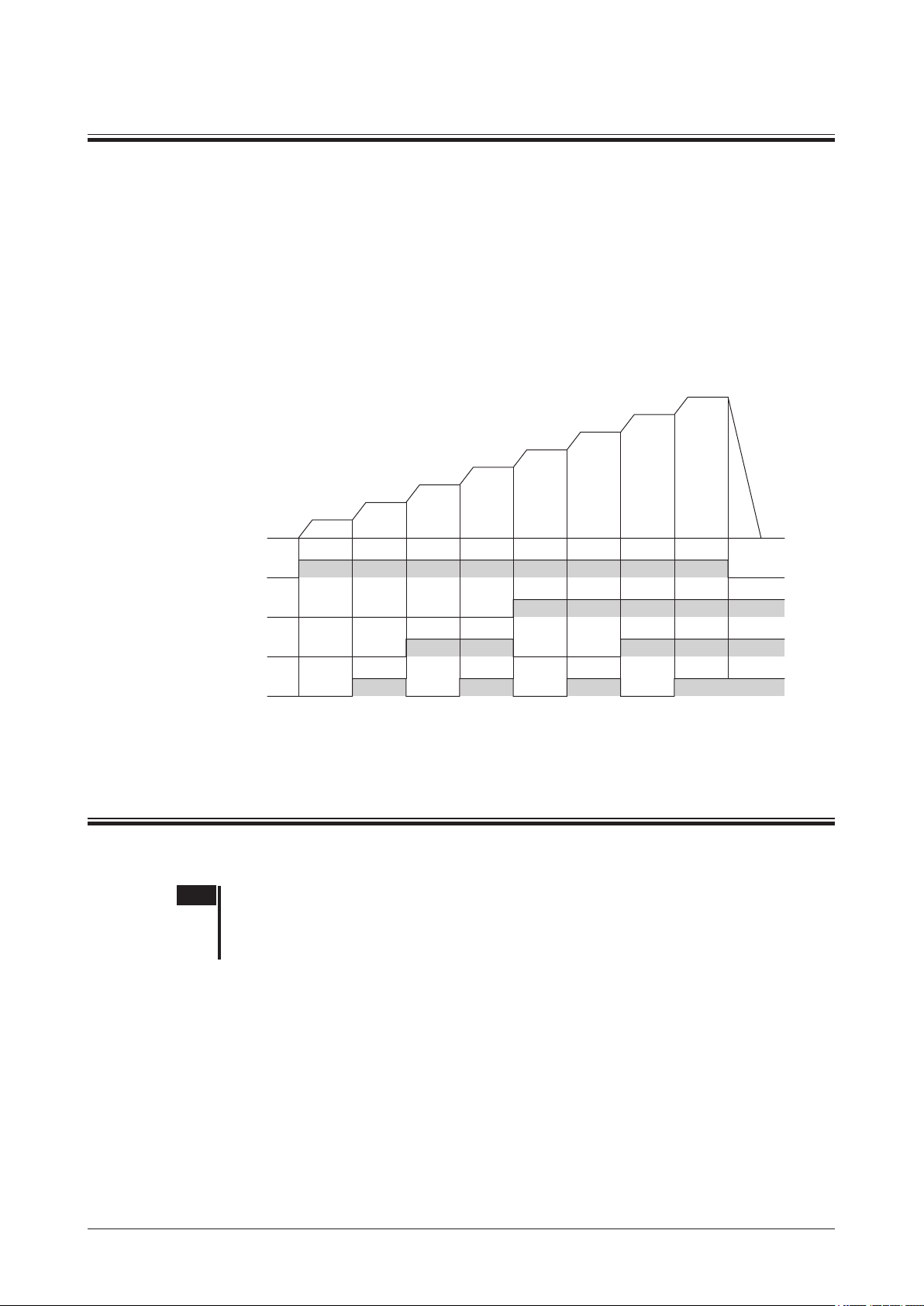
9 Extended functions
OFF
Extended functions
The following functions can be extended using the
For details, refer to the operating manual for each product.
•A maximum of eight speeds can be set.
•The torque can be limited.
•The assignments of I/O signals can be changed.
•The speed, alarm code and load factor can be displayed.
•I/Os can be monitored.
•Warnings can be output.
•Test operation can be performed.
•Data can be copied.
Example of operation pattern with maximum eight speed settings
No.1
No.0
Motor operation
FWD input
M2 input
M1 input
M0 input
ON
OFF
ON
OFF
ON
OFF
ON
OPX-2A
No.2
No.3
or
MEXE02
No.4
.
No.7
No.6
No.5
10 Inspection
It is recommended that the items listed below be inspected regularly after motor operation. If any abnormality is
found, stop using the motor and call our Technical Support Line.
Note •Never measure insulation resistance or conduct a dielectric strength test with the motor and
driver connected. Doing so may damage the motor/driver.
•The driver uses semiconductor elements, so handle it with due care. Electrostatic discharge can
damage the driver.
Inspection items
Conrm that:
•The motor/gearhead mounting screws are not loose.
•The bearing (ball bearing) and other parts of the motor are not generating noise.
•The bearing (ball bearing) and gear meshing parts of the gearhead are not generating noise.
•The motor/gearhead output shaft is not misaligned with the load shaft.
•The cables are free from damage or stress and are securely connected to the driver.
•The openings in the driver are not blocked.
•The driver mounting screws and power connection terminal screws are not loose.
•The power elements and smoothing capacitors in the driver are not generating an abnormal smell or having
abnormalities.
−47−
Page 48

Protection function
1 2 3 1 2 3
11 Protection function
When an alarm generates and the driver's protective function is actuated, the ALARM-OUT1 output will turn OFF.
*
In the case of a standard type, the motor coasts to a stop, and then the holding power of the motor output shaft is lost.
When the motor is an electromagnetic brake type, the motor stops instantaneously and the electromagnetic brake is
actuated to hold the shaft in position.
The ALARM LED blinks at the same time. You can check the type of the alarm by counting the number of times the
ALARM LED blinks.
ON in the
*
compatible mode
FBL
Ⅱ
Flashing pattern example: Sensor error (three ashes)
0.3 s0.3 s 1.5 s
To reset an alarm, be sure to remove the cause of the alarm and then perform one of the following operations:
•Turn the ALARM-RESET input ON for at least 10 ms. (Refer to p.31 for details.)
•Turn off the power, wait for at least 30 sec, and then cycle the power.
Note •Alarms cannot be reset if the FWD input or REV input is ON or the motor is running. Be sure to
stop the motor before resetting any alarm.
•Alarms caused by damage to the motor or driver itself cannot be reset using the method
explained above. Please contact your nearest ofce.
•Make sure the ALARM-RESET input remains ON for at least 10 ms. If the ON period is too
short, the alarm may not be reset.
•If an external stop alarm generates, the motor stops instantaneously.
Alarm list
No. of ALARM
LED blinks
2 Overload
3
4 Overvoltage
5 Undervoltage
6 Overspeed
Alarm name Cause Remedial action
•Decrease the load.
•Review the operation pattern
settings such as the acceleration/
deceleration time.
Check the connection between the
driver and motor.
•Check the main power supply
voltage.
•If this alarm occurs during
operation, reduce the load
or increase the acceleration/
deceleration time.
•Use a regeneration unit.
•Check the main power supply
voltage.
•Check the wiring of the power
supply cable.
•Decrease the load.
•Review the operation pattern
settings such as the acceleration/
deceleration time.
Sensor error
Initial sensor error
A load exceeding the rated
torque was applied to the
motor for 5 seconds or more.
The motor sensor signal line
experienced an open circuit
during operation, or the signal
connector came off.
The motor sensor signal line
broke or signal connector
came off before the main
power supply was turned on.
•The main power-supply
voltage became higher than
the rated voltage by approx.
20%.
•A load exceeding the
allowable gravitational
capacity of the motor is
driven or sudden starting/
stopping of a large inertial
load is performed.
The main power-supply
voltage became lower than
the rated voltage by approx.
40%.
The rotating speed of the
motor output shaft exceeded
approx. 4800 r/min.
Reset using the
ALARM-RESET
input
Possible
−48−
Page 49

Protection function
No. of ALARM
LED blinks
7 Overcurrent
8 EEPROM error
9
10 External stop
11
14
Only when EXT-ERROR is assigned using the
*1
This alarm generates when the “Initial operation inhibition” function has been enabled using the
*2
not generate in the
This alarm does not generate when the torque limit is set to less than 200% using the
*3
Alarm name Cause Remedial action
Check the wiring between the
driver and motor for damage. If the
alarm does not reset even after
the power supply has been cycled,
contact your nearest ofce.
Initialize the parameters if the
OPX-2A
alarm does not reset even after
the power supply has been cycled,
contact your nearest ofce.
Check the EXT-ERROR input.
Turn the FWD input and REV input
OFF, and then cycle the main
power supply.
Check the connection between the
driver and motor.
.
or
•The power consumption of the
regeneration resistor exceeds
the permissible level. Review
the load condition and operating
conditions.
•Check the connection between
the lead wires of the regeneration
unit/thermostat output and CN5
on the driver.
•Before turning on the main power
supply of the driver, turn on the
external power supply for input
signals.
OPX-2A
Overheated
regeneration unit
*1
Initial operation
inhibition
Main circuit output
error
*2
*3
compatible mode.
FBL
Ⅱ
Excessive current has own
through the driver due to
ground fault, etc.
•Stored data was damaged.
•Data became no longer
writable or readable.
•Overheating of the
regeneration unit was
detected.
•Lead wires of the thermostat
output of the regeneration
unit broke during operation.
•The main power supply
of the driver was turned
on before turning on the
external power supply for
input signals.
The EXT-ERROR input turned
OFF.
The main power supply was
cycled when the FWD input or
REV input was ON.
The motor drive wire broke or
motor power connector came
off.
OPX-2A
or
MEXE02
MEXE02
or
is used. If the
MEXE02
or
.
OPX-2A
MEXE02
Reset using the
ALARM-RESET
input
Not possible
Possible
. This alarm does
Note Cycle the power to reset the overcurrent and EEPROM error alarms. To cycle the power, wait for at least
30 seconds after the power is cut off and then turn it back on. If the unit does not operate properly after the
power is cycled, internal circuit damage is suspected. Please contact your nearest ofce.
−49−
Page 50

Troubleshooting and remedial actions
12 Troubleshooting and remedial actions
An erroneous speed setting or connection may prevent the motor/driver from operating properly.
If proper motor operation cannot be achieved, take an appropriate action by referring to this chapter. If the information
provided here does not help, please contact your nearest Oriental Motor ofce.
Problem Likely cause Corrective action
The motor doesn’t operate.
The motor turns in the
opposite direction to the
specied direction.
•Unstable motor operation
•Large vibration
The motor doesn’t stop
instantaneously.
The electromagnetic brake
does not hold.
The power supply is not connected
correctly.
Both the FWD input and REV input are
OFF.
Both the FWD input and REV input are
ON.
The internal potentiometer is not adjusted.
The potentiometer is not selected correctly.
The external potentiometer or external DC
voltage is not connected correctly.
The ALARM LED (red) is blinking.
Electromagnetic brake is not released.
(electromagnetic brake motor only).
The FWD input and REV input are
connected wrongly or otherwise not
connected correctly.
The combination type parallel shaft
gearhead is using a gear with a gear ratio
of 30:1, 50:1 or 100:1.
A combination type hollow shaft at
gearhead is used.
The motor (gearhead) output shaft is not
misaligned with the load shaft.
Effect of noise.
The STOP-MODE input is ON.
The inertial load is large.
The MB-FREE input is ON. Turn OFF the MB-FREE input.
Check the connection of the power supply.
Turn ON either the FWD input or REV input one at
a time.
Turn ON either the FWD input or REV input one at
a time.
The factory setting is 0 r/min. Turn the internal
potentiometer clockwise.
Turn the M0 input OFF when using the internal
potentiometer. Turn the M0 input ON when using
the external potentiometer.
Check the connection of the external potentiometer
or external DC voltage.
An alarm generated due to a protective function
being triggered. Refer to p.48 to reset the alarm.
Turn ON the MB-FREE input.
Check the connection of the FWD input and
REV input. The motor turns in the clockwise
direction when the FWD input is ON, and in the
counterclockwise direction when the REV input is
ON.
When the gear ratio of the combination type
parallel shaft gearhead is 30, 50 or 100, the
rotating direction of the gear output shaft is
opposite the rotating direction of the motor output
shaft. Accordingly, reverse the FWD input and
REV input operations.
•With a combination type hollow shaft at
gearhead, the rotating direction of the gear
output shaft is opposite the rotating direction of
the motor output shaft. Accordingly, reverse the
FWD input and REV input operations.
•Is the gearhead viewed in the correct direction?
With a combination type hollow shaft at
gearhead, the rotating direction of the gearhead
changes according to the direction in which the
gearhead is viewed.
Check the coupling condition of the motor
(gearhead) output shaft and load shaft.
Check the operation only with the motor, driver and
other external equipment required for operation. If
an effect of noise has been conrmed, implement
the following countermeasures:
•Move the unit farther away from noise generation
sources.
•Review the wiring.
•Change the signal cables to a shielded type.
•Install ferrite cores.
To cause the motor to stop instantaneously, turn
OFF the STOP-MODE input.
Reduce the load inertia or connect the accessory
regeneration unit (sold separately) to check the
inertial load.
−50−
Page 51

13 Accessories (sold separately)
Connection cable
This cable is used to extend the wiring distance between the driver and motor. Connection can be extended to a maximum
of 20.4 m (66.9 ft.). Flexible connection cables are also available. You can connect up to three connection cables.
•Standard type
Connection cable
Length
[m (ft.)]
1 (3.3)
2 (6.6)
3 (9.8)
5 (16.4)
7 (23.0)
10 (32.8)
15 (49.2)
20 (65.6)
CC01BLE
CC02BLE
CC03BLE
CC05BLE
CC07BLE
CC10BLE
CC15BLE
CC20BLE
Model
•Standard type
Flexible connection cable
Length
[m (ft.)]
1 (3.3)
2 (6.6)
3 (9.8)
5 (16.4)
7 (23.0)
10 (32.8)
15 (49.2)
20 (65.6)
Model
CC01BLER
CC02BLER
CC03BLER
CC05BLER
CC07BLER
CC10BLER
CC15BLER
CC20BLER
•Electromagnetic brake type
Connection cable
Length
[m (ft.)]
1 (3.3)
2 (6.6)
3 (9.8)
5 (16.4)
7 (23.0)
10 (32.8)
15 (49.2)
20 (65.6)
Model
CC01BLEM
CC02BLEM
CC03BLEM
CC05BLEM
CC07BLEM
CC10BLEM
CC15BLEM
CC20BLEM
Accessories (sold separately)
•Electromagnetic brake type
Flexible connection cable
Length
[m (ft.)]
1 (3.3)
2 (6.6)
3 (9.8)
5 (16.4)
7 (23.0)
10 (32.8)
15 (49.2)
20 (65.6)
Model
CC01BLEMR
CC02BLEMR
CC03BLEMR
CC05BLEMR
CC07BLEMR
CC10BLEMR
CC15BLEMR
CC20BLEMR
Regeneration unit
Connect the regeneration unit if gravitational operation or sudden starting/stopping of a large inertial load, will be
repeated frequently.
Model:
EPRC-400P
Digital speed indicator
This device displays the speed of the motor output shaft and reduced speed of the gearhead output shaft.
Model:
SDM496
Note •The
SDM496
Series unit, the
SDM496
•The
is not certied under safety standards. If the
BLE
Series unit does not conform to safety standards, either.
cannot be used with the source logic.
• Basic connection (30 pulses/revolution)
SDM496 Driver
SPEED signal input SPEED-OUT (+)
Selection of 12 pulses or
30 pulses
Power supply input
Single-phase100-240 V
50/60 Hz
FG FG
Data setter
7
5
6
2
10
9
This data setter can be used to set or monitor operation data and parameters.
Model:
OPX-2A
SPEED-OUT (
SDM496
is combined with a
• FBLⅡcompatible mode (12 pulses/revolution)
SDM496 Driver
SPEED signal input SPEED-OUT (+)
-
)GND
Selection of 12 pulses or
30 pulses
Power supply input
Single-phase 100-240 V
50/60 Hz
7
5
Not connected.
6
2
10
9
BLE
SPEED-OUT (
-
)GND
Communication cable for the support software
Be sure to purchase the communication cable for the support software when connecting a driver and PC in which the
support software
MEXE02
has been installed.
This is a set of a PC interface cable and USB cable. The cable is connected to the USB port on the PC.
Model:
The
MEXE02
CC05IF-USB
can be downloaded from Oriental Motor Website Download Page. Also, the
[5 m (16.4 ft.)]
MEXE02
is provided in
the form of a storage medium. For details, check out our web site or contact your nearest Oriental Motor sales ofce.
DIN rail mounting plate
When mounting the driver to a DIN rail, use a DIN rail mounting plate. Use a DIN rail 35 mm (1.38 in.) wide.
Model:
PADP03
−51−
Page 52

•Unauthorized reproduction or copying of all or part of this manual is prohibited.
• Please contact your nearest Oriental Motor oce for further information.
If a new copy is required to replace an original manual that has been damaged or lost, please contact your nearest Oriental Motor
branch or sales ofce.
•Oriental Motor shall not be liable whatsoever for any problems relating to industrial property rights arising from use of any
information, circuit, equipment or device provided or referenced in this manual.
•Characteristics, specications and dimensions are subject to change without notice.
•While we make every effort to offer accurate information in the manual, we welcome your input. Should you nd unclear
descriptions, errors or omissions, please contact the nearest ofce.
•
is a registered trademark or trademark of Oriental Motor Co., Ltd., in Japan and other countries.
Other product names and company names mentioned in this manual may be registered trademarks or trademarks of their respective
companies and are hereby acknowledged. The third-party products mentioned in this manual are recommended products, and
references to their names shall not be construed as any form of performance guarantee. Oriental Motor is not liable whatsoever for
the performance of these third-party products.
© Copyright
ORIENTAL MOTOR CO., LTD. 2011
Published in December 2017
Technical Support Tel:(800)468-3982
8:30 A.M. to 5:00 P.M., P.S.T. (M-F)
7:30 A.M. to 5:00 P.M., C.S.T. (M-F)
www.orientalmotor.com
Tel:+55-11-3266-6018
www.orientalmotor.com.br
Schiessstraße 44, 40549 Düsseldorf, Germany
Technical Support Tel:00 800/22 55 66 22
www.orientalmotor.de
Tel:01256-347090
www.oriental-motor.co.uk
Tel:01 47 86 97 50
www.orientalmotor.fr
Tel:02-93906346
www.orientalmotor.it
Singapore
Tel:1800-8420280
www.orientalmotor.com.sg
Tel:1800-806161
www.orientalmotor.com.my
Tel:1800-888-881
www.orientalmotor.co.th
Tel:+91-80-41125586
www.orientalmotor.co.in
Tel:0800-060708
www.orientalmotor.com.tw
Tel:400-820-6516
www.orientalmotor.com.cn
Korea
Tel:080-777-2042
www.inaom.co.kr
Hong Kong Branch
Tel:+852-2427-9800
4-8-1 Higashiueno, Taito-ku, Tokyo
110-8536 Japan
Tel:03-6744-0361
www.orientalmotor.co.jp
 Loading...