

Page 1
Brushless Motor and Driver Package
BLE Series
RS-485 communication type
USER MANUAL
(Motor) (Driver)
Thank you for purchasing an Oriental Motor product.
This Operating Manual describes product handling procedures and safety precautions.
•Please read it thoroughly to ensure safe operation.
•Always keep the manual where it is readily available.
HM-5140-3
Page 2

1 Entry
1 Operating Manuals for the BLE Series .........6
2 Introduction ...................................................7
3 Safety precautions ........................................8
4 Precautions for use .....................................10
5 Systemconguration ..................................12
6 Preparation ..................................................13
6.1 Checking the product...................................13
6.2 How to identify the product model ...............13
6.3 Combination tables ......................................14
6.4 Names and functions of parts ......................15
2 Installation and
connection
1 Installation ...................................................20
1.1 Installation location ......................................20
1.2 Installation overview ....................................20
1.3 Installing the combination type •
parallel shaft gearhead ................................22
1.4 Installing the round shaft type......................23
1.5 Installing the combination type •
hollow shaft at gearhead............................23
1.6 Installing a load to the combination type •
parallel gearhead or round shaft type ..........25
1.7 Installing a load to the combination type •
hollow shaft at gearhead............................26
1.8 Permissible radial load and
permissible axial load ..................................28
1.9 Installing the driver ......................................29
1.10 Installing the external potentiometer
(supplied) .....................................................30
1.11 Installing the regeneration unit
(accessory) ..................................................30
2 Connection ...................................................31
2.1 Connection example ....................................31
2.2 Connecting the power supply ......................32
2.3 Grounding ....................................................32
2.4 Connecting the motor and driver .................33
2.5 Connecting the 24 VDC power supply.........34
2.6 Selecting the input signal power supply ......34
2.7 Connecting the I/O signals ..........................34
2.8 Connecting an external speed setter ...........37
2.9 Connecting the data setter ..........................38
2.10 Connecting the RS-485 communication
cable ............................................................38
2.11 Test operation ..............................................39
2.12 Connecting the regeneration unit ................39
2.13 Connection diagram (example) ...................41
3 Explanation of I/O signals ..........................44
3.1 Assignment of direct I/O ..............................44
Assignment to the input terminals .....................44
Changing the logic level setting of input
signals ...............................................................45
Assignment to the output terminals ...................46
3.2 Assignment of network I/O ..........................47
Assignment of input signals ...............................47
Assignment to the output terminals ...................49
3.3 Input signals ................................................50
3.4 Output signals..............................................52
3.5 General signals (R0 to R15) ........................53
3 Method of control via I/O
1 Guidance ......................................................56
2 Operation data and parameter ...................58
2.1 Operation data .............................................58
2.2 Parameter ....................................................59
Parameter list ....................................................59
Function parameter ...........................................60
I/O function parameter .......................................61
I/O function parameter (RS-485) .......................62
Analog adjust parameter ...................................63
Alarm/warning parameter ..................................63
Utilities parameter ..............................................63
Operation parameter .........................................64
Communication parameter ................................65
3 Method of control via I/O ............................66
3.1 Operation data .............................................66
3.2 Setting the rotation speed............................66
Analog setting ....................................................66
Digital setting .....................................................68
3.3 Setting the acceleration time and
deceleration time .........................................68
When setting the rotation speed with analog
setting ................................................................68
When setting the rotation speed with digital
setting ................................................................68
3.4 Setting the torque limiting ............................69
3.5 Running/stopping the motor ........................70
Operation ...........................................................70
Stop ...................................................................70
Rotation direction ...............................................70
3.6 Example of operation pattern ......................71
3.7 Multi-motor control .......................................71
Using an external potentiometer ........................71
Using external DC voltage .................................72
How to adjust the speed dierence ...................72
3.8 Multi-speed operation ..................................73
−2−
Page 3

4 Method of control via
Modbus RTU
(RS-485 communication)
1 Guidance ......................................................76
2 Communicationspecications ..................79
3 Setting the switches ....................................81
4 Setting the RS-485 communication ...........83
5 Communication mode and
communication timing ................................84
5.1 Communication mode..................................84
5.2 Communication timing .................................84
6 Message .......................................................85
6.1 Query ...........................................................85
6.2 Response ....................................................87
7 Function code ..............................................89
7.1 Reading from a holding register(s) ..............89
7.2 Writing to a holding register .........................90
7.3 Diagnosis .....................................................91
7.4 Writing to multiple holding registers .............92
8 Register address list ...................................93
8.1 Operation commands ..................................93
8.2 Maintenance commands .............................94
8.3 Monitor commands ......................................95
8.4 Parameter R/W commands .........................98
Operation data ...................................................98
User parameters ................................................99
9 Group send ................................................104
Input/output of remote I/O ................................118
Details of remote I/O assignment ....................120
2 Method of control via MECHATROLINK
communication ..........................................122
2.1 Guidance ...................................................122
2.2 Setting the switches...................................125
2.3 I/O eld map for the
2.4 I/O eld map for the
2.5 Communication format ..............................128
Remote I/O input .............................................128
Remote I/O output ...........................................128
Remote register input ......................................128
Remote register output ....................................129
NETC01-M2
NETC01-M3
.............126
.............127
3 Details of remote I/O .................................130
3.1 Input signals to the driver ..........................130
3.2 Output signals from the driver ...................131
4 Command code list ...................................132
4.1 Group function ...........................................132
4.2 Maintenance command .............................133
4.3 Monitor command ......................................134
4.4 Operation data ...........................................135
4.5 User parameters ........................................135
Function parameter .........................................136
I/O function parameter .....................................136
I/O function parameter (RS-485) .....................137
Analog adjust parameter .................................138
Alarm/warning parameter ................................138
Utilities parameter ............................................138
Operation parameter .......................................138
Communication parameter ..............................139
10 Detection of communication errors ........106
10.1 Communication errors ..............................106
10.2 Alarms and warnings ................................106
11 Timing charts ............................................107
5 Method of control via
industrial network
1 Method of control via CC-Link
communication .......................................... 110
1.1 Guidance ................................................... 110
1.2 Setting the switches................................... 113
1.3 Remote register list.................................... 114
1.4 Assignment for remote I/O of 6 axes
connection mode ....................................... 114
Assignment list of remote I/O ..........................114
Input/output of remote I/O ................................115
Details of remote I/O assignment ....................116
1.5 Assignment for remote I/O of 12 axes
connection mode ....................................... 117
Assignment list of remote I/O ..........................117
6 Inspection,
troubleshooting and
remedial actions
1 Inspection ..................................................142
2 Alarms, warnings and
communication errors ..............................143
2.1 Alarms .......................................................143
Alarm reset ......................................................143
Alarm records ..................................................143
Alarm list ..........................................................144
2.2 Warnings ...................................................145
Warning list ......................................................145
Warning records ..............................................145
2.3 Communication errors ...............................146
Communication error list ..................................146
Communication error records ..........................146
3 Troubleshooting and remedial actions ...147
−3−
Page 4

7 Reference
1 Specications ............................................150
1.1 Specications ............................................150
1.2 General specications ...............................152
1.3 Dimension..................................................152
2 Standard and CE Marking .........................153
3 Installing and wiring in compliance
with EMC Directive ....................................155
8 Appendix
1 Accessories (sold separately) ..................160
2 Related products (sold separately) .........162
−4−
Page 5

1 Entry
This part explains the composition of the operating manuals, the product overview, specications and safety
standards as well as the name and function of each part and others.
Table of contents
1 Operating Manuals for the
BLE
2 Introduction ..........................................7
3 Safety precautions ...............................8
4 Precautions for use ............................10
5 System conguration ..........................12
6 Preparation .........................................13
6.1 Checking the product ............................ 13
6.2 How to identify the product model ......... 13
6.3 Combination tables ............................... 14
6.4 Names and functions of parts ............... 15
Series ............................................6
Page 6

Operating Manuals for the BLE Series
1 Operating Manuals for the BLE Series
Operating manuals for the
BLE
Series
RS-485 communication type are listed below.
FLEX
After reading the following manuals, keep them in a convenient place so that you can reference them at any time.
Applicable product Type of operating manual Model Description of operating manual
This manual explains the functions
as well as the installation method and
others for the motor and driver.
This manual explains the function,
installation and connection of the motor
and driver as well as operating method.
This manual explains the functions
and installation/connection method
as well as data setting method and
others for the accessory
separately).
This manual explains how to set data
using the accessory data setting
software
This manual explains the functions,
installation/connection method as well
as the operating method and others for
the network converter.
MEXE02
OPX-2A
(sold separately).
(sold
BLE
Series FLEX
RS-485
communication type
Data setter
Data setting software
MEXE02
Network converter
OPX-2A
OPERATING MANUAL
(supplied with the product)
USER MANUAL
(this manual)
OPERATING MANUAL HP-5056
OPERATING MANUAL HM-60131
CC-Link Ver.1.1 compatible
NETC01-CC
USER MANUAL
CC-Link Ver.2 compatible
NETC02-CC
USER MANUAL
MECHATROLINK-Ⅱcompatible
NETC01-M2
USER MANUAL
MECHATROLINK-Ⅲcompatible
NETC01-M3
USER MANUAL
HM-5143
HM-5140
HM-60089
HM-60305
HM-60091
HM-60093
−6−
1 Entry
Page 7

2 Introduction
Before use
Only qualied and educated personnel should work with the product.
Use the product correctly after thoroughly reading the section p.8 "3 Safety precautions".
The product described in this manual has been designed and manufactured to be incorporated in general industrial
equipment. Do not use for any other purpose. Oriental Motor Co., Ltd. is not responsible for any damage caused
through failure to observe this warning.
Product overview
This is a motor and driver package product consisting of a compact, high-torque brushless motor and driver
compatible with I/O control and RS-485 communication.
The operation data and parameters can be set using an accessory data setter
MEXE02
Accessories
The operation data and parameters can be set using an accessory data setter
MEXE02
Related products
The
converter.
(sold separately), or via RS-485 communication.
, or via RS-485 communication. Provide the
BLE
Series
RS-485 communication type can be used via various network when connecting to a network
FLEX
OPX-2A
or
MEXE02
OPX-2A
OPX-2A
as necessary.
or data setting software
or data setting software
Introduction
Network converter Supported network
NETC01-CC
NETC02-CC
NETC01-M2
NETC01-M3
CC-Link communication (Ver.1.1 compatible)
CC-Link communication (Ver.2 compatible)
MECHATROLINK-Ⅱcommunication
MECHATROLINK-Ⅲcommunication
Notation rules
The following term is used in explanation of this manual.
Term Description
Master controller
This is a generic name for a programmable controller,
master module and so on.
Hazardous substances
The products do not contain the substances exceeding the restriction values of RoHS Directive (2011/65/EU).
1 Entry
−7−
Page 8

Safety precautions
Note
3 Safety precautions
The precautions described below are intended to prevent danger or injury to the user and other personnel through safe,
correct use of the product. Use the product only after carefully reading and fully understanding these instructions.
Handling the product without observing the instructions that accompany a "Warning"
symbol may result in serious injury or death.
Handling the product without observing the instructions that accompany a "Caution"
symbol may result in injury or property damage.
The items under this heading contain important handling instructions that the user should
observe to ensure the safe use of the product.
Do not use the product in a place exposed to explosive, ammable or corrosive gases or water splashes or near
•
combustible materials. Doing so may result in re, electric shock or injury.
Only qualied and educated personnel should be allowed to perform installation, connection, operation and
•
inspection/troubleshooting of the product. Handling by unqualied personnel may result in re, electric shock,
injury or equipment damage.
•Do not move, install, connect or inspect the product while the power is supplied. Perform these operations after
turning o the power. Failure to observe these instructions may result in electric shock.
•The terminals on the driver’s front panel marked with
touch these terminals while the power is on to avoid the risk of re or electric shock.
•Do not use a non-electromagnetic brake type motor in a vertical application. If the driver’s protection function is
activated, the motor will stop and the moving part of the equipment will drop, thereby causing injury or equipment
damage.
•Do not use the brake mechanism of the electromagnetic brake motor as a safety brake. It is intended to hold the
moving parts and motor position. Doing so may result in injury or damage to equipment.
•If the driver protective function has been activated, remove the cause and reset the protective function. Continuing
to operate the equipment without removing the cause of problem will lead to a motor or driver malfunction,
resulting in injury or equipment damage.
Use a specied motor (gearhead) and driver combination. Failure to do so may result in re, electric shock or
•
equipment damage.
•The motor and driver are Class I equipment.
When installing the motor and driver, connect their Protective Earth Terminals. Failure to do so may result in
electric shock.
Install the motor and driver in an enclosure. Failure to do so may result in electric shock or injury.
•
Securely connect the cables in accordance with the connection examples. Failure to do so may result in re or
•
electric shock.
Do not forcibly bend, pull or pinch the cables. Doing so may result in re or electric shock.
•
Do not machine or modify the motor cable or connection cable. Doing so may result in electric shock or re.
•
Be sure to observe the specied cable sizes. Use of unspecied cable sizes may result in re.
•
Observe the specied screw tightening torque when connecting terminals to the terminal block. Failure to do so
•
may result in electric shock or equipment damage.
Always keep the power supply voltage of the driver within the specied range. Failure to do so may result in re or
•
electric shock.
When using the electromagnetic brake motor, do not turn the MB-FREE input ON while a load is held in vertical
•
direction. Otherwise, the holding power of the motor and electromagnetic brake will be lost, causing personal
injury or damage to equipment.
•When using the electromagnetic brake motor in vertical drive (gravitational operation), be sure to operate after
checking the load condition. If a load in excess of the rated torque is applied or the small torque limiting value is
set using a
to equipment.
Always turn o the power before performing maintenance/inspection. Failure to do so may result in electric shock.
•
•Do not touch the motor or driver when measuring insulation resistance or performing a dielectric strength test.
Accidental contact may result in electric shock.
Do not touch the connection terminals on the driver immediately (until the CHARGE LED turns o) after the
•
power is turned o. Residual voltage may cause electric shock.
Regularly check the openings in the driver for accumulated dust. Accumulated dust may cause re.
•
•Do not disassemble or modify the motor (gearhead) and driver. Doing so may result in electric shock, injury or
equipment damage. Should you require inspection or repair of internal parts, please contact the Oriental Motor
branch or sales oce from which you purchased the product.
OPX-2A, MEXE02
or RS-485 communication, the load may fall. This may result in injury or damage
symbol indicate the presence of high voltage. Do not
−8−
1 Entry
Page 9

Safety precautions
Do not use the product in conditions exceeding the motor (gearhead) or driver specications. Doing so may result
•
in electric shock, re, injury or equipment damage.
Do not insert an object into the openings in the driver. Doing so may result in re, electric shock or injury.
•
•Do not touch the motor (gearhead) or driver while operating or immediately after stopping. The surface of the
motor (gearhead) or driver may be hot and cause a skin burn(s).
•Do not carry the product by holding the motor (gearhead) output shaft or any of the cables. Doing so may result in
injury.
Do not place around the motor and driver any object blocking the air ow. Doing so may result in equipment
•
damage.
•Do not touch the motor output shaft (end of shaft or pinion) with bare hands. Doing so may result in injury.
When assembling the motor (pinion shaft) with the gearhead, exercise caution not to pinch your ngers or other
•
parts of your body between the motor and gearhead. Injury may result.
•Securely install the motor (gearhead) and driver to their respective mounting plates. Inappropriate installation may
cause the motor/driver to detach and fall, resulting in injury or equipment damage.
Provide a cover on the rotating part (output shaft) of the motor (gearhead). Failure to do so may result in injury.
•
When installing the motor (gearhead) in the equipment, exercise caution not to pinch your ngers or other parts of
•
your body between the equipment and motor or gearhead. Injury may result.
•Securely install the load on the motor output shaft. Inappropriate installation may result in injury.
Be sure to ground the motor and driver to prevent them from being damaged by static electricity. Failure to do so
•
may result in re or damage to equipment.
Use a 24 VDC power supply with reinforced insulation on its primary and secondary sides. Failure to do so may
•
result in electric shock.
•Provide an emergency stop device or emergency stop circuit external to the equipment so that the entire equipment
will operate safely in the event of a system failure or malfunction. Failure to do so may result in injury.
Immediately when trouble has occurred, stop running and turn o the driver power. Failure to do so may result in
•
re, electric shock or injury.
•Do not touch the rotating part (output shaft) during operation. Doing so may result in injury.
The motor surface temperature may exceed 70 °C (158 °F) even under normal operating
•
conditions. If the operator is allowed to approach a running motor, attach a warning label as shown
to the right in a conspicuous position. Failure to do so may result in skin burn(s).
Use an insulated screwdriver to adjust the switches in the driver. Failure to do so may result in
•
electric shock.
•Dispose the product correctly in accordance with laws and regulations, or instructions of local governments.
Warning label
Warning information
A warning label with handling instructions is attached on the driver. Be sure to observe the instructions on the label
when handling the driver.
1 Entry
−9−
Page 10

Precautions for use
4 Precautions for use
This chapter explains the restrictions and other items you should take heed of when using the
485 communication type.
BLE
Series
FLEX
RS-
•Connect protective devices to the power line
Connect a circuit breaker or earth leakage breaker to the driver’s power line to protect the primary circuit. If an
earth leakage breaker is to be installed, use one incorporating high-frequency noise elimination measures. Refer to
"Preventing leakage current" below for the selection of protective devices.
•Use an electromagnetic brake type for an application involving vertical travel
When the motor is used in an application involving vertical travel, use an electromagnetic brake type to hold the load
in position.
Do not use a solid-state relay (SSR) to turn on/o the power
•
A circuit that turns on/o the power via a solid-state relay (SSR) may damage the motor and driver.
•Do not conduct the insulation resistance measurement or dielectric strength test with the motor
and driver connected.
Conducting the insulation resistance measurement or dielectric strength test with the motor and driver connected may
result in damage to the product.
•Grease measures
On rare occasions, grease may ooze out from the gearhead. If there is concern over possible environmental damage
resulting from the leakage of grease, check for grease stains during regular inspections. Alternatively, install an oil
pan or other device to prevent leakage from causing further damage. Oil leakage may lead to problems in the user's
equipment or products.
Apply grease to the hollow output shaft of a hollow shaft at gearhead
•
When using a hollow shaft at gearhead, apply grease (molybdenum disulde grease, etc.) on the surface of the load
shaft and inner walls of the hollow output shaft to prevent seizure.
•Preventing leakage current
Stray capacitance exists between the driver’s current-carrying line and other current-carrying lines, the earth and the
motor, respectively. A high-frequency current may leak out through such capacitance, having a detrimental eect on
the surrounding equipment. The actual leakage current depends on the driver’s switching frequency, the length of
wiring between the driver and motor, and so on.
When connecting an earth leakage breaker, use one of the following products oering resistance against high
frequency current:
Mitsubishi Electric Corporation: NV series
•Noise elimination measures
Provide noise elimination measures to prevent a motor or driver malfunction caused by external noise.
For more eective elimination of noise, use a shielded I/O signal cable or attach ferrite cores if a non-shielded cable is
used. Refer to "3 Installing and wiring in compliance with EMC Directive" on p.155 for the noise elimination measures.
•Note on connecting a power supply whose positive terminal is grounded
The data edit connector (CN3), I/O signal connectors (CN5/CN6) and RS-485 communication connectors (CN7/CN8)
are not insulated. When grounding the positive terminal of the power supply, do not connect any equipment (PC, etc.)
whose negative terminal is grounded. Doing so may cause the these equipment and driver to short, damaging both.
•The driver uses semiconductor elements, so be extremely careful when handling them
Electrostatic discharge can damage the driver.
Be sure to ground the motor and driver to prevent them from being damaged by electric shock or static electricity.
•Use a connection cable (supplied or accessory) when extending the wiring distance between the
motor and driver
•When using the motor in operation such as vertical drive (gravitational operation) or a large
inertial load drive, use an accessory regeneration unit
The driver may be damaged if the regeneration energy generated during vertical drive (gravitational operation) or
sudden starting/stopping of a large inertial load exceeds the allowable limit that can be absorbed by the driver.
The accessory regeneration unit
driver.
EPRC-400P
is designed to discharge the regenerated energy, thereby protecting the
EPRC-400P
(sold separately).
−10−
1 Entry
Page 11

Precautions for use
•Saving data to the non-volatile memory
Do not turn o the 24 VDC power supply while writing the data to the non-volatile memory, and also do not turn o
within 5 seconds after the completion of writing the data. Doing so may abort writing the data and cause a EEPROM
error alarm to generate.
The non-volatile memory can be rewritten approximately 100,000 times.
1 Entry
−11−
Page 12
System conguration
Connect I/O signals.
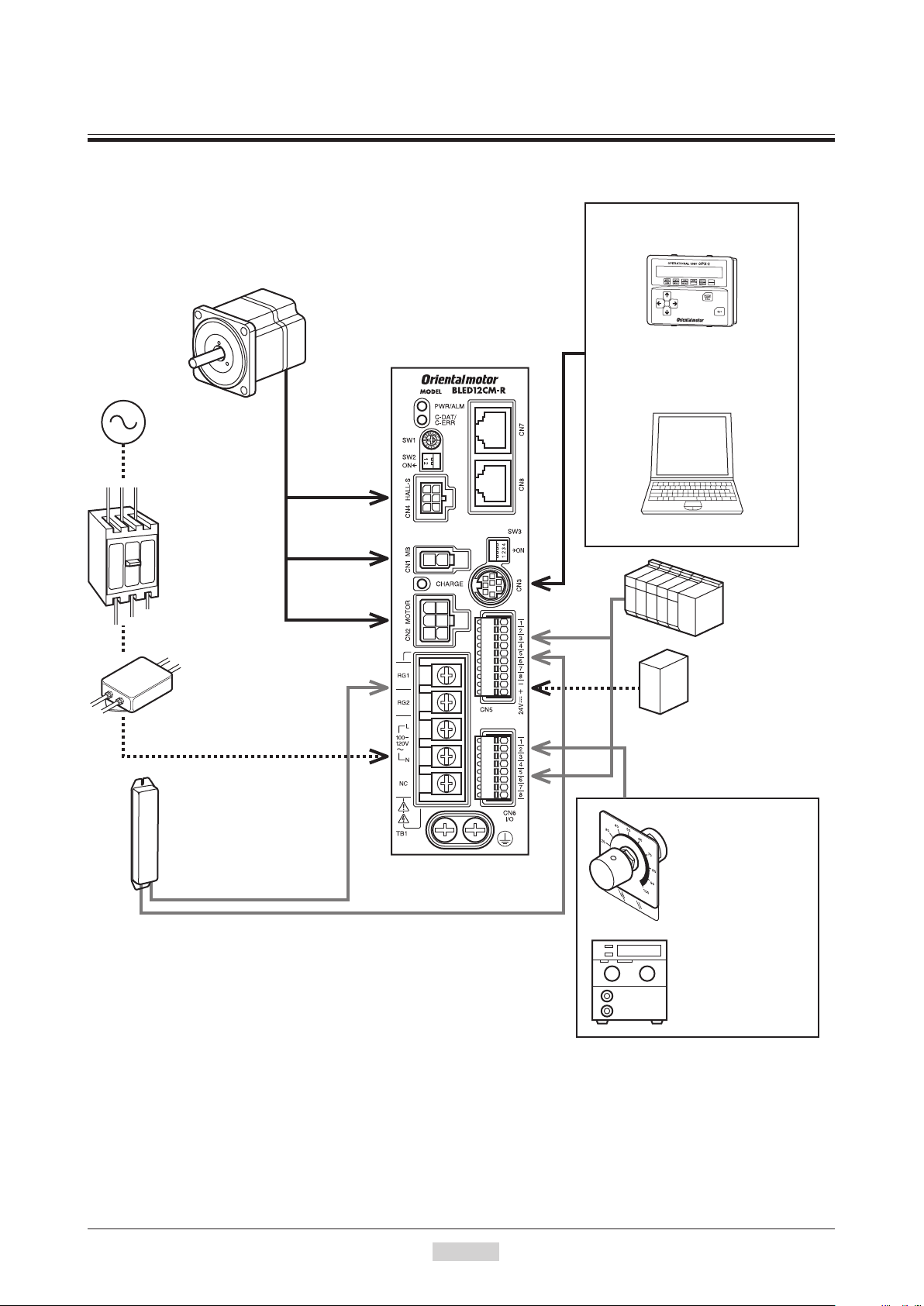
5 Systemconguration
An example of system conguration using the
Illustration shows the electromagnetic brake type.
Motor
Driver
Connection
Power supply
Make sure power supply
voltage does not exceed
the rated voltage.
Circuit breaker or
earth leakage
cable
(supplied or
accessory)
Motor signal
connector
Electromagnetic
brake connector
breaker
Always connect a
breaker to protect the
primary circuit.
Motor power
connector
BLE
Series
RS-485 communication type is shown below.
FLEX
Data setter OPX-2A
(accessory)
Or
PC in which the data
editing software MEXE02
has been installed
The PC must be supplied by the user.
Input
External control
equipment
Mains filter
Use a mains filter to eliminate
noise. It effectively reduces
noise generated from the power
source or driver.
Regeneration unit
EPRC-400P (accessory)
Use this regeneration unit when
using the motor in operation
such as vertical drive
(gravitational operation) or
a large inertial load drive.
Output
Or
24 VDC power
supply
Be sure to connect it.
External potentiometer
(supplied)
Connect this potentiometer
to set the motor speed
externally.
External DC voltage
Connect an appropriate
power supply to set the
motor speed using DC
voltage.
−12−
1 Entry
Page 13

6 Preparation
BLE 5 12 A M R 5 S - 1
: Hollow shaft flat gearhead
Series name
This chapter explains the items you should check, as well as the name and function of each part.
6.1 Checking the product
Verify that the items listed below are included. Report any missing or damaged items to the branch or sales oce
from which you purchased the product.
Verify the model number of the purchased product against the number shown on the package label.
Check the model number of the motor and driver against the number shown on the nameplate. Model names for
motor and driver combinations are shown on p.14.
•Motor ............................................................. 1 unit (with a gearhead, only for combination type)
•Driver ............................................................ 1 unit
•Connection cable ........................................... 1 piece (Only models with a supplied connection cable)
•CN5 connector (10 pins) ............................... 1 piece
•CN6 connector (8 pins) ................................. 1 piece
•External potentiometer .................................. 1 piece
•Signal cable for external potentiometer ........ 1 piece [1 m (3.3 ft.)]
•OPERATING MANUAL ..............................1 copy
Accessories for combination type • parallel shaft gearhead
•Hexagonal socket head screw set ............1 set
(Hexagonal socket head screw, at washer, spring washer and nut, pieces each)
•Parallel key ..............................................1 piece
Preparation
Accessories for combination type • hollow shaft at gearhead
•Hexagonal socket head screw set ............1 set
•Safety cover ............................................1 piece
•Safety cover mounting screw ..................2 pieces
•Parallel key ..............................................1 piece
6.2 How to identify the product model
(Hexagonal socket head screw, at washer, spring washer and nut, 4 pieces each)
Number: Length (m) of a supplied connection cable
None: Without a supplied connection cable
Gearhead type for combination type S: Parallel shaft gearhead
F
Number: Gear ratio for combination type
A: Round shaft type
R: RS-485 communication type
M: Electromagnetic brake type
None: Standard type
Power supply voltage A: Single-phase 100-120 V
C: Single-phase 200-240 V, Three-phase 200-240 V
Output power 3: 30 W
6: 60 W
12: 120 W
Motor size 2: 60 mm (2.36 in.) sq.
4: 80 mm (3.15 in.) sq.
5: 90 mm (3.54 in.) sq.
1 Entry
−13−
Page 14

Preparation
6.3 Combination tables
in the model names indicates a number representing the gear ratio.
••
indicates a number representing the length of a connection cable.
••
•The combination types come with the motor and gearhead pre-assembled.
Standard type
Motor type Model Motor model Gearhead model Driver model
Combination type •
parallel shaft gearhead
Combination type •
hollow shaft at
gearhead
Round shaft type
BLE23ARS-
BLE23CRS-
BLE46ARS-
BLE46CRS-
BLE512ARS-
BLE512CRS-
BLE23ARF-
BLE23CRF-
BLE46ARF-
BLE46CRF-
BLE512ARF-
BLE512CRF-
BLE23ARA-
BLE23CRA-
BLE46ARA-
BLE46CRA-
BLE512ARA-
BLE512CRA-
BLEM23-GFS GFS2G
BLEM46-GFS GFS4G
BLEM512-GFS GFS5G
BLEM23-GFS GFS2GFR
BLEM46-GFS GFS4GFR
BLEM512-GFS GFS5GFR
BLEM23-A
BLEM46-A
BLEM512-A
−
BLED3AM-R
BLED3CM-R
BLED6AM-R
BLED6CM-R
BLED12AM-R
BLED12CM-R
BLED3AM-R
BLED3CM-R
BLED6AM-R
BLED6CM-R
BLED12AM-R
BLED12CM-R
BLED3AM-R
BLED3CM-R
BLED6AM-R
BLED6CM-R
BLED12AM-R
BLED12CM-R
Electromagnetic brake type
Motor type Model Motor model Gearhead model Driver model
BLE23AMRS-
BLE23CMRS-
Combination type •
parallel shaft gearhead
Combination type •
hollow shaft at
gearhead
Round shaft type
BLE46AMRS-
BLE46CMRS-
BLE512AMRS-
BLE512CMRS-
BLE23AMRF-
BLE23CMRF-
BLE46AMRF-
BLE46CMRF-
BLE512AMRF-
BLE512CMRF-
BLE23AMRA-
BLE23CMRA-
BLE46AMRA-
BLE46CMRA-
BLE512AMRA-
BLE512CMRA-
BLEM23M2-GFS GFS2G
BLEM46M2-GFS GFS4G
BLEM512M2-GFS GFS5G
BLEM23M2-GFS GFS2GFR
BLEM46M2-GFS GFS4GFR
BLEM512M2-GFS GFS5GFR
BLEM23M2-A
BLEM46M2-A
BLEM512M2-A
−
BLED3AM-R
BLED3CM-R
BLED6AM-R
BLED6CM-R
BLED12AM-R
BLED12CM-R
BLED3AM-R
BLED3CM-R
BLED6AM-R
BLED6CM-R
BLED12AM-R
BLED12CM-R
BLED3AM-R
BLED3CM-R
BLED6AM-R
BLED6CM-R
BLED12AM-R
BLED12CM-R
−14−
1 Entry
Page 15
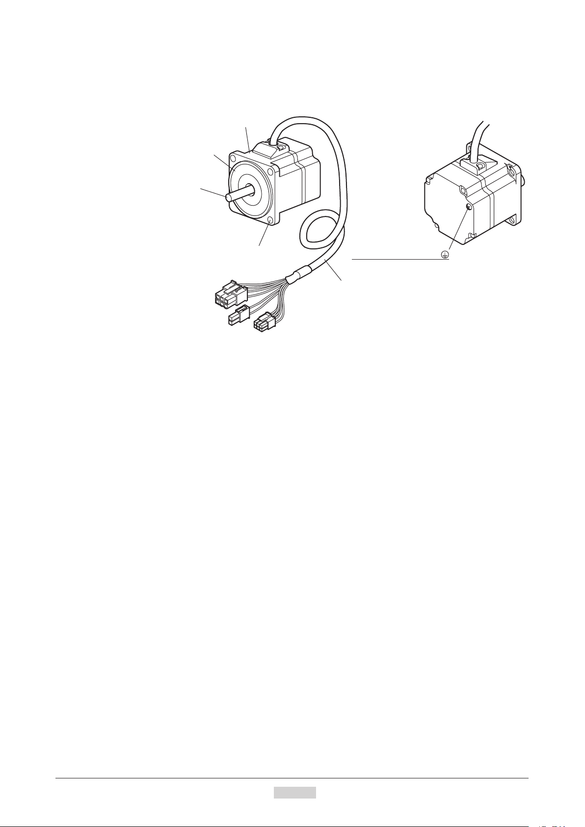
6.4 Names and functions of parts
Motor signal connector
Electromagnetic brake connector
Motor
Motor
Illustration shows the electromagnetic brake type.
Pilot
Output shaft
Preparation
Mounting hole (4 locations)
Motor power connector
Protective Earth Terminal
Be sure to ground.
Motor cable
1 Entry
−15−
Page 16
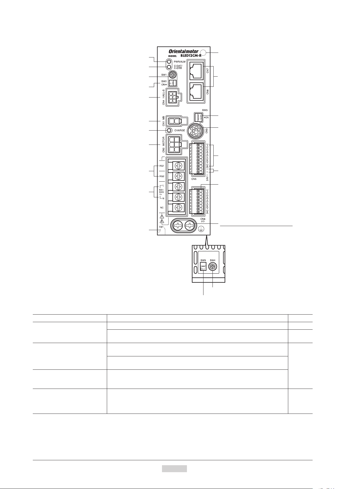
Preparation
24 VDC power supply input terminal (CN5)
Electromagnetic brake connector (CN1)
Function setting switch2 (SW5)
Driver
PWR/ALM LED
C-DAT/C-ERR LED
Address number setting switch (SW1)
Test operation mode switch (SW2)
Motor signal connector (CN4)
CHARGE LED
Motor connector (CN2)
Regeneration resistor terminal (TB1)
Main power supply input terminal (TB1)
Mounting hole (at the back)
RS-485 communication connector
(CN7/CN8)
Function setting switch1 (SW3)
Data edit connector (CN3)
Input signal connector (CN5)
I/O signal connector (CN6)
Name Description Ref.
PWR/ALM LED
C-DAT/C-ERR LED
CHARGE LED (Red)
Address number setting switch
(SW1)
Protective Earth Terminal
Mounting hole (at the back)
Be sure to ground the driver using either
of the Protective Earth Terminals.
Transmission rate setting switch (SW4)
PWR (Green): This LED is lit while the 24 VDC power is input. −
ALM (Red): This LED will blink when an alarm generates. It is possible to check
the generated alarm by counting the number of times the LED blinks.
C-DAT (Green): This LED will blink or illuminate steadily when the driver is
communicating with the master station properly via RS-485 communication.
C-ERR (Red): This LED will illuminate when the RS-485 communication error
occurs with the master station.
This LED is lit while the main power is input. After the main power has been
turned o, the LED will turn o once the residual voltage in the driver drops to a
safe level.
Use this switch when controlling the system via RS-485 communication. Using
this switch in combination with the SW5-No.1 of the function setting switch2, the
address number of RS-485 communication can be set.
Factory setting: 0
p.143
−
p.81
p.113
p.125
−16−
1 Entry
Page 17

Preparation
Name Description Ref.
SW2-No.1: This switch is used to check the connection between the motor and
driver before establishing a communication. When having connected properly,
Test operation mode switch
(SW2)
setting the SW2-No.1 to the ON side causes the motor to rotate at low speed in
the forward direction.
p.39
Factory setting: OFF
SW2-No.2: Not used. (Keep this switch OFF.)
•SW3-No.1: Not used. (Keep this switch OFF.)
−
•SW3-No.2: Not used. (Keep this switch OFF.)
•SW3-No.3: This switch is used to select the power supply for I/O signals (use
the built-in power supply or external power supply). To control the operation
Function setting switch1 (SW3)
using relays and switches, set the SW3-No.3 to the ON side to select the built-in
power supply.
p.34
Factory setting: OFF
•SW3-No.4: Use this switch when controlling the system via RS-485
communication. The termination resistor (120 Ω) of RS-485 communication can
be set.
Factory setting: OFF
Transmission rate setting switch
(SW4)
Use this switch when controlling the system via RS-485 communication. The
transmission rate of RS-485 communication can be set.
Factory setting: 7
Use this switch when controlling the system via RS-485 communication.
p.81
p.113
p.125
•SW5-No.1: Using this switch in combination with the address number setting
Function setting switch2 (SW5)
switch (SW1), the address number of RS-485 communication can be set.
Factory setting: OFF
•SW5-No.2: The protocol of RS-485 communication can be set.
Factory setting: OFF
Electromagnetic brake connector
(CN1)
Connects the electromagnetic brake connector. (Electromagnetic brake type only)
p.33
Motor connector (CN2) Connects the motor power connector.
Data edit connector (CN3) Connects a PC in which the
MEXE02
has been installed, or the
OPX-2A
. p.38
Motor signal connector (CN4) Connects the motor signal connector. p.33
Input signal connector (CN5) Connects the input signals. p.34
24 VCD power input terminals
(CN5)
I/O signal connector (CN6)
RS-485 communication
connectors (CN7/CN8)
Regeneration resistor terminal
(TB1)
Connects the control power supply of the driver.
+: +24 VDC power supply input
p.34
−: Power supply GND [This is shared with the common wire of input signals (0 V)]
•Connects the external potentiometer (supplied) or external DC power supply.
•Connects the output signals.
p.34
Connects the RS-485 communication cable. p.38
Connects an accessory regeneration unit
EPRC-400P
(sold separately). p.39
Connects to the main power supply.
•Single-phase 100-120 VAC
L, N: Connects a single-phase 100-120 VAC power supply
Main power supply input terminal
(TB1)
NC: Not used.
•Single-phase 200-240 VAC
L1, L2: Connects a single-phase 200-240 VAC power supply
p.32
L3: Not used.
•Three-phase 200-240 VAC
L1, L2, L3: Connects a three-phase 200-240 VAC power supply
Protective Earth T erminal Ground this terminal using a grounding wire of AWG18 to 14 (0.75 to 2.0 mm
Mounting holes
(two locations at the back)
These mounting holes are used to install the driver with screws (M4). p.29
2
).
1 Entry
−17−
Page 18

−18−
1 Entry
Page 19

2 Installation and
connection
This part explains the installation method of the product, the mounting method of a load and the connection
method as well as I/O signals.
Table of contents
1 Installation ..........................................20
1.1 Installation location ................................ 20
1.2 Installation overview .............................. 20
1.3 Installing the combination type •
parallel shaft gearhead ..........................22
1.4 Installing the round shaft type ............... 23
1.5 Installing the combination type •
hollow shaft at gearhead .....................23
1.6 Installing a load to the combination type •
parallel gearhead or round shaft type ...25
1.7 Installing a load to the combination type •
hollow shaft at gearhead .....................26
1.8 Permissible radial load and permissible
axial load ...............................................28
1.9 Installing the driver ................................ 29
1.10 Installing the external potentiometer
(supplied) ..............................................30
1.11 Installing the regeneration unit
(accessory) ............................................30
2 Connection .........................................31
2.1 Connection example ............................. 31
2.2 Connecting the power supply ................ 32
2.3 Grounding .............................................32
2.4 Connecting the motor and driver ........... 33
2.5 Connecting the 24 VDC power
supply ....................................................34
2.6 Selecting the input signal power
supply ....................................................34
2.7 Connecting the I/O signals .................... 34
2.8 Connecting an external speed setter .... 37
2.9 Connecting the data setter .................... 38
2.10 Connecting the RS-485 communication
cable ......................................................38
2.11 Test operation ........................................39
2.12 Connecting the regeneration unit .......... 39
2.13 Connection diagram (example) ............. 41
3 Explanation of I/O signals ..................44
3.1 Assignment of direct I/O ........................ 44
Assignment to the input terminals ................... 44
Changing the logic level setting of input
signals .............................................................. 45
Assignment to the output terminals ................. 46
3.2 Assignment of network I/O .................... 47
Assignment of input signals ............................ 47
Assignment to the output terminals ................. 49
3.3 Input signals .......................................... 50
3.4 Output signals ....................................... 52
3.5 General signals (R0 to R15) .................. 53
Page 20
Installation
• Combination type • parallel shaft gearhead
• Round shaft type
1 Installation
This chapter explains the installation location and installation methods of the motor and driver, as well as how to
install a load and external potentiometer.
1.1 Installation location
The motor and driver are designed and manufactured for use as a component to be installed inside equipment.
Install them in a well-ventilated location that provides easy access for inspection. The location must also satisfy the
following conditions:
•Inside an enclosure that is installed indoors (provide vent holes)
Ambient temperature: 0 to +50 °C (+32 to +122 °F) (non-freezing)
•
•Ambient humidity: 85% or less (non-condensing)
•Area not exposed to direct sun
•Area free of excessive amount of dust, iron particles or the like
•Area free of excessive salt
•Area that is free of explosive atmosphere or toxic gas (such as sulfuric gas) or liquid
•Area not subject to splashing water (rain, water droplets), oil (oil droplets) or other liquids
•Area not subject to continuous vibration or excessive shocks
•Area free of excessive electromagnetic noise (from welders, power machinery, etc.)
Area free of radioactive materials, magnetic elds or vacuum
•
•Altitude Up to 1000 m (3300 ft.) above sea level
1.2 Installation overview
This section explains an overview of how to install the motor and driver. Refer to each applicable section for details.
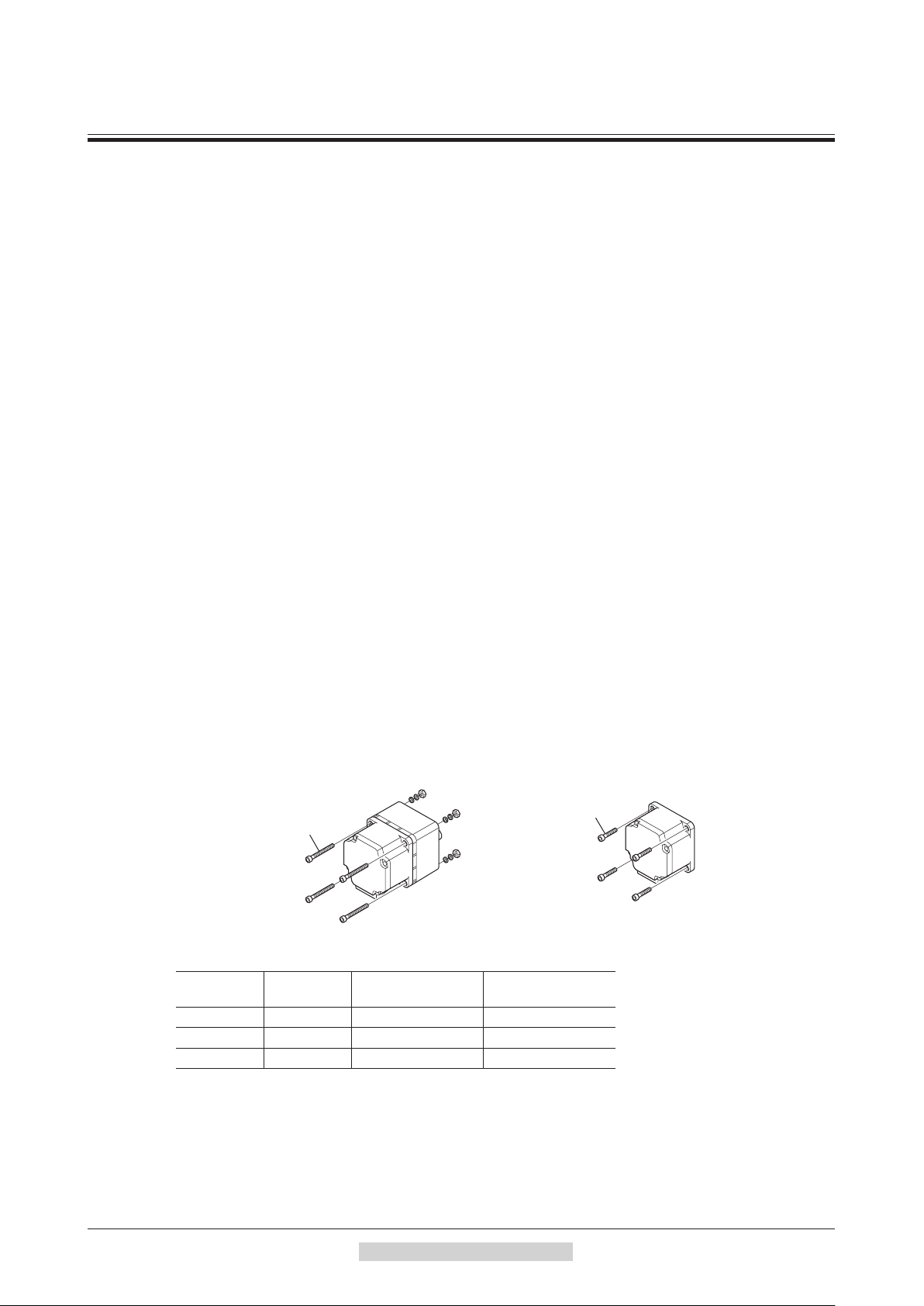
Installing the combination type • parallel shaft gearhead and round shaft
type
Secure the motor using the hexagonal socket head screws through the four mounting holes. Tighten the nuts until no
gaps remain between the motor and mounting plate.
The combination type • parallel shaft gearheads come with a set of hexagonal socket head screws. Round shaft types
do not come with hexagonal socket head screws. Hexagonal socket head screws must be provided by the user if round
shaft types are used.
For machining dimension of the mounting plate or installing/removing method of the gearhead, see p.22 for the
combination type • parallel shaft gearhead and p.23 for the round shaft type.
Hexagonal socket head
screw set (supplied)
Hexagonal socket head screw set (supplied with the combination type • parallel shaft gearhead)
Model
BLE23
BLE46
BLE512
* When the supplied hexagonal socket head screw set is used.
Nominal
thread size
M4 1.8 N·m (15.9 lb-in) 5 mm (0.20 in.)
M6 6.4 N·m (56 lb-in) 8 mm (0.31 in.)
M8 15.5 N·m (137 lb-in) 12 mm (0.47 in.)
Tightening torque
Hexagonal socket
head screw
Maximum applicable
plate thickness
∗
−20−
2 Installation and connection
Page 21

Mounting plate
MotorRear
flat gearhead
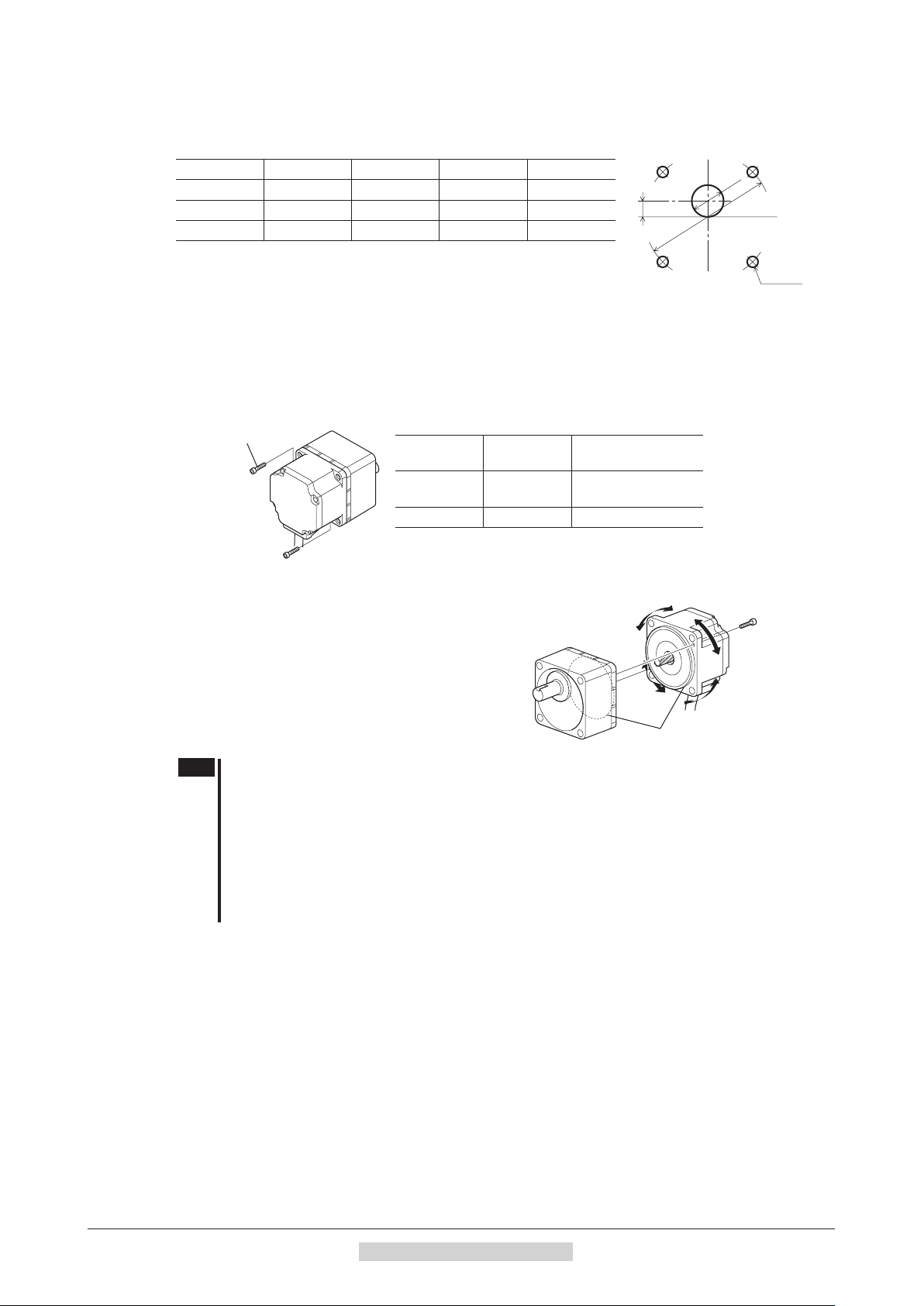
Installingthecombinationtype•hollowshaftatgearhead
A combination type • hollow shaft at gearhead can be installed by using
either its front or rear side as the mounting surface. Install the supplied
hexagonal socket head screw set in the four mounting holes you drilled and
tighten the nuts until no gaps remain between the motor and mounting plate.
Also, attach the supplied safety cover to the hollow output shaft on the end
opposite from the one where the load shaft is installed.
Refer to p.23 for the installation method and how to install/remove the gearhead.
Front
Hollow shaft
Hexagonal socket head screw set (supplied)
Model
BLE23
BLE46
BLE512
* When the supplied hexagonal socket head screw set is used.
Nominal
thread size
M5 3.8 N·m (33 lb-in) 5 mm (0.20 in.)
M6 6.4 N·m (56 lb-in) 8 mm (0.31 in.)
M8 15.5 N·m (137 lb-in) 12 mm (0.47 in.)
Tightening torque
Maximum applicable
plate thickness
∗
Installing the driver
The driver can be installed in two dierent ways. Refer to p.29 for the specic installation methods.
•Use screws (M4: not supplied) to secure the driver through the mounting holes (two locations) provided at the back
of the driver.
Secure the driver on a DIN rail using the accessory DIN-rail mounting plate (sold separately).
•
Installation
2 Installation and connection
−21−
Page 22
Installation
C
4×ØD
Hexagonal socket
Pilot section
position to a desired
1.3 Installing the combination type • parallel shaft gearhead
Mounting hole dimensions [unit: mm (in.)]
Model ØA ØB C ØD
BLE23
BLE46
BLE512
70 (2.76) 24 (0.94) 10 (0.39) 4.5 (0.177)
94 (3.70) 34 (1.34) 13 (0.51) 6.5 (0.256)
104 (4.09) 40 (1.57) 18 (0.71) 8.5 (0.335)
ØA
ØB
ØB indicates the external dimensions of the product.
Drill holes with a minimum diameter of ØB +1 mm (0.04 in.).
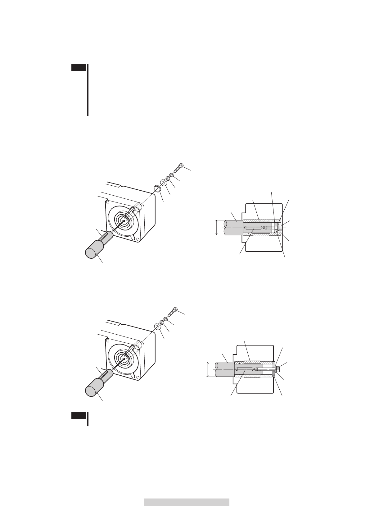
Removing/Installing the gearhead
To replace the gearhead or change the cable outlet direction, remove the screws assembling the gearhead. The
gearhead can be removed and the motor cable position changed to a desired 90° direction.
1. Remove the hexagonal socket head screws (2 pieces) assembling the motor and gearhead and detach
the motor from the gearhead.
head screw
2. Using the pilot sections of the motor and gearhead as guides, install the gearhead to the motor and
tighten the hexagonal socket head screws.
At this time, the motor cable position can be changed to
a desired 90° direction. When installing the gearhead,
slowly rotate it clockwise/counterclockwise to prevent the
pinion of the motor output shaft from contacting the side
panel or gear of the gearhead. Also conrm that no gaps
remain between the motor ange surface and the end face
of the gearhead’s pilot section.
Assembly screws
Model
BLE23
BLE46
BLE512
Nominal
thread size
Tightening torque
M2.6 0.4 N·m (3.5 lb-in)
M3 0.6 N·m (5.3 lb-in)
Change the cable
90° direction.
Note
•Do not forcibly assemble the motor and gearhead. Also, do not let metal objects or other foreign
matters enter the gearhead. The pinion of the motor output shaft or gear may be damaged,
resulting in noise or shorter service life.
•Do not allow dust to attach to the pilot sections of the motor and gearhead. Also, assemble the
motor and gearhead carefully by not pinching the O-ring at the motor’s pilot section. If the O-ring
is crushed or severed, grease may leak from the gearhead.
•The hexagonal socket head screws assembling the motor and gearhead are used to attach
the motor and gearhead temporarily. When installing the product, be sure to use the supplied
hexagonal socket head screws (4 pieces).
−22−
2 Installation and connection
Page 23
1.4 Installing the round shaft type
+ 0.030
0
+ 0.0012
0
+ 0.030
0
+ 0.0012
0
+ 0.035
0
+ 0.0014
0
Safety cover
Hexagonal nut
+0.039
0
+ 0.0015
0
+0.039
0
+ 0.0015
0
+0.039
0
+ 0.0015
0
Mounting plate size
Install the motor to a mounting plate of the following size or larger, so that the motor case temperature will not exceed
90 °C (194 °F).
Model Size of mounting plate Thickness Material
BLE23
BLE46
BLE512
* Electromagnetic brake type: 135×135 mm (5.31×5.31 in.)
Mounting hole dimensions [unit: mm (in.)]
Model ØA B ØCH7 ØD
BLE23
BLE46
BLE512
ØC indicates the pilot diameter on the ange.
115×115 mm (4.53×4.53 in.)
135×135 mm (5.31×5.31 in.)
165×165 mm (6.50×6.50 in.)
70 (2.76) 49.5 (1.949)
94 (3.70) 66.47 (2.616)
104 (4.09) 73.54 (2.895)
∗
5 mm (0.20 in.) Aluminum alloy
54
(2.1260
73
(2.8740
83
(3.2677
)
)
)
4.5 (0.177)
6.5 (0.256)
8.5 (0.335)
B
ØA
ØCH7
Installation
B
ØD
Note
Fit the boss on the gearhead mounting surface into a pilot receiving hole.
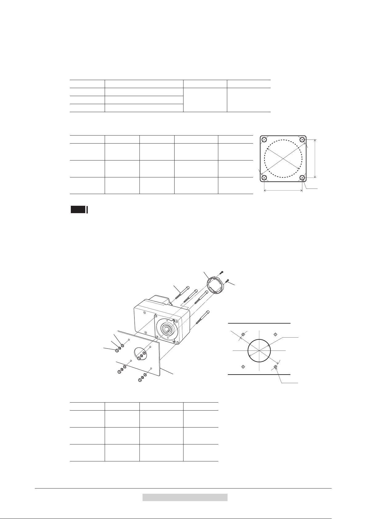
1.5 Installingthecombinationtype•hollowshaftatgearhead
Using the front side as the mounting surface
When the gearhead is installed by using its front side as the mounting surface, use the boss of the output shaft to align
the center.
Hexagonal socket head screw
Flat washer
Spring washer
Mounting plate
Safety cover
mounting screw (M3)
• Mounting hole dimension
ØA
ØBH8
4×ØC
Mounting hole dimensions [unit: mm (in.)]
Model ØA ØBH8 ØC
BLE23
BLE46
BLE512
70 (2.76)
94 (3.70)
104 (4.09)
34
(1.34
38
(1.50
50
(1.97
)
)
)
2 Installation and connection
5.5 (0.22)
6.5 (0.26)
8.5 (0.33)
−23−
Page 24
Installation
Safety cover
Safety cover
mounting screw (M3)
Hexagonal nut
Hexagonal socket
Change the cable position to
one of three 90° directions.
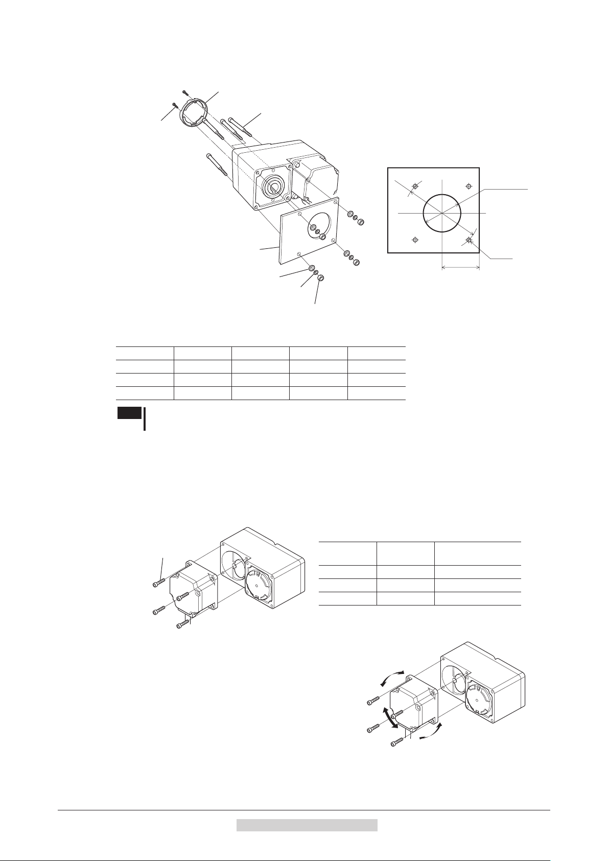
Using the rear side as the mounting surface
Hexagonal socket head screw
• Mounting hole dimension
ØA
ØD or more
Mounting plate
E
Flat washer
Spring washer
4×ØC
Mounting hole dimensions [unit: mm (in.)]
Model ØA ØC ØD E
BLE23
BLE46
BLE512
Note
When installing the gearhead by using its rear side as the mounting surface, prevent contact
70 (2.76) 5.5 (0.22) 25 (0.98) 29 (1.14)
94 (3.70) 6.5 (0.26) 30 (1.18) 39 (1.54)
104 (4.09) 8.5 (0.33) 35 (1.38) 44 (1.73)
between the mounting plate and motor by keeping dimension E below the specied value.
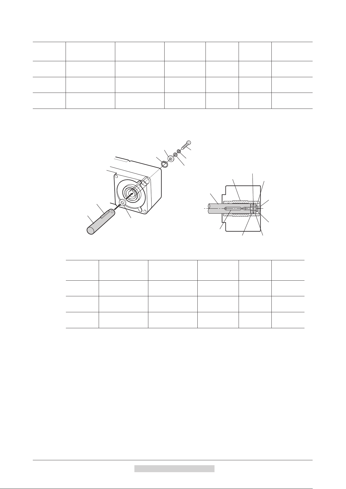
Removing/Installing the gearhead
To replace the gearhead or change the cable outlet direction, remove the screws assembling the gearhead.
The gearhead can be removed and the motor cable position changed to one of three 90° directions. Note that the
motor cable cannot be positioned in the direction where the cable faces the gearhead output shaft.
1. Remove the hexagonal socket head screws (4 pieces) attaching the gearhead and motor and detach
the motor from the gearhead.
Assembly screws
head screw
Model
BLE23
BLE46
BLE512
Nominal
thread size
M4 1.8 N·m (15.9 lb-in)
M6 6.4 N·m (56 lb-in)
M8 15.5 N·m (137 lb-in)
Tightening torque
−24−
2. Using the pilot sections of the motor and gearhead as
guides, install the motor to the gearhead and tighten the
hexagonal socket head screws.
At this time, the motor cable position can be changed to one
of three 90° directions. Install the motor carefully to prevent
the pinion of the motor output shaft from contacting the
casing or gear of the gearhead. Also conrm that no gaps
remain between the motor ange surface and the end face of
the gearhead’s pilot section.
2 Installation and connection
Page 25

Installation
will obstruct the cable.
Spacer
Transmission
Note
•Do not forcibly assemble the motor and gearhead. Also, do not let metal objects or other foreign
matters enter the gearhead. The pinion of the motor output shaft or gear may be damaged,
resulting in noise or shorter service life.
•Do not allow dust to attach to the pilot sections of the motor and gearhead. Also, assemble the
motor carefully by not pinching the O-ring at the motor’s pilot section. If the O-ring is pinched,
the coupling strength will drop and grease may leak from the gearhead.
•The motor cable position cannot be changed to the
direction where the cable faces the gearhead output
shaft, because the gearhead case will obstruct the cable.
The gearhead case
1.6 Installing a load to the combination type • parallel gearhead or round shaft type
When installing a load on the motor (gearhead), align the center of the motor output shaft (gearhead output shaft) with
the center of the load shaft.
Note
•When coupling the motor (gearhead) with a load, pay attention to centering, belt tension,
parallelism of pulleys, etc. Also, rmly secure the tightening screws of the coupling or pulleys.
•When installing a load, do not damage the motor output shaft (gearhead output shaft) or
bearing. Forcing in the load by driving it with a hammer, etc., may break the bearing. Do not
apply any excessive force to the output shaft.
•Do not modify or machine the motor (gearhead) output shaft. The bearing may be damaged or
motor (gearhead) may break.
Output shaft shape
•Combination type • parallel shaft gearhead
A key slot is provided on the output shaft of each combination type • parallel shaft gearhead. Form a key slot on the
load side and secure the load using the supplied parallel key.
•Round shaft type
A at section is provided on the motor output shaft of each round shaft type. Apply a double-point screw, etc., at the
at section to rmly secure the load and prevent it from spinning.
How to install a load
•Using a coupling
Align the centerline of the motor (gearhead) output shaft with the centerline of the load shaft.
•Using a belt
Adjust the motor (gearhead) output shaft to lie parallel with the load shaft and form right angles between the output
shaft/load shaft and the line connecting the centers of both pulleys.
•Using a gear
Adjust the motor (gearhead) output shaft to lie parallel with the gear shaft and allow the output shaft to mesh correctly
with the centers of the gear teeth.
•When using the output axis tip screw hole of a gearhead
Use a screw hole provided at the tip of the output shaft as an
auxiliary means for preventing the transfer mechanism from
disengaging. (
Gearhead
model name
GFS4G
GFS5G
type have no output shaft tip screw hole.)
GFS2G
Output shaft tip screw hole
M5, Eective depth 10 mm (0.39 in.)
M6, Eective depth 12 mm (0.47 in.)
Screw
parts
Fixed screw
2 Installation and connection
−25−
Page 26
Installation
Stepped load shaft
Parallel key
Hexagonal socket
Stepped load shaft
Parallel key
Hexagonal socket
1.7 Installingaloadtothecombinationtype•hollowshaftatgearhead
If the motor is subject to a strong impact upon instantaneous stop or receives a large overhung load, use a stepped
load shaft.
Note
Apply grease (molybdenum disulde grease, etc.) on the surface of the load shaft and inner
•
walls of the hollow output shaft to prevent seizure.
•When installing a load, do not damage the hollow output shaft or bearing of the gearhead.
Forcing in the load by driving it with a hammer, etc. may break the bearing. Do not apply any
excessive force to the hollow output shaft.
•Do not modify or machine the hollow output shaft of the gearhead. Doing so may damage the
bearings and destroy the gearhead.
Stepped load shaft
•Mounting method using retaining ring
Secure the retaining ring to the load shaft by tightening the hexagonal socket head screw over a spacer, at washer
and spring washer.
Hexagonal socket head screw
Spring washer
Flat washer
Spacer
Retaining ring
Hollow output shaft
Load shaft
ØD
Retaining ring
Flat washer
head screw
Spring washer
Parallel key
Spacer
•Mounting method using end plate
Secure the end plate to the load shaft by tightening the hexagonal socket head screw over a at washer and spring
washer.
Hexagonal socket head screw
Spring washer
Flat washer
End plate
Load shaft
Note
The safety cover (supplied) cannot be attached due to contact between the safety cover and
hexagonal socket head screw. Take safety measures against rotating part.
Hollow output shaft
Flat washer
head screw
ØD
Spring washer
End plateParallel key
−26−
2 Installation and connection
Page 27
+0.027
0
+ 0.0011
0
0
-
0.018
0
-
0.0007
+0.027
0
+ 0.0011
0
0
-
0.018
0
-
0.0007
+0.033
0
+ 0.0013
0
0
-
0.021
0
-
0.0008
Spacer
Hexagonal socket
Spacer
Load shaft
+0.027
0
+ 0.0011
0
0
-
0.018
0
-
0.0007
+0.027
0
+ 0.0011
0
0
-
0.018
0
-
0.0007
+0.033
0
+ 0.0013
0
0
-
0.021
0
-
0.0008
Recommended load shaft installation dimensions [Unit: mm (in.)]
•
Model
BLE23
BLE46
BLE512
Inner diameter of
hollow shaft (H8)
Ø12
(Ø0.4724
)
Ø15
(Ø0.5906
)
Ø20
(Ø0.7874
)
Recommended
diameter of load
shaft (h7)
Ø12
(Ø0.4724
Ø15
(Ø0.5906
Ø20
(Ø0.7874
Nominal diameter
of retaining ring
Ø12 (Ø0.47) M4 3 (0.12) 20 (0.79)
)
Ø15 (Ø0.59) M5 4 (0.16) 25 (0.98)
)
Ø20 (Ø0.79) M6 5 (0.20) 30 (1.18)
)
Non-stepped load shaft
Install a spacer on the load shaft side and secure the retaining ring to the load shaft by tightening the hexagonal socket
head screw over a spacer, at washer and spring washer.
Applicable
screw
Spacer
thickness
Installation
Outer diameter
of stepped shaft
(ØD)
Spacer
Retaining ring
Hexagonal socket head screw
Spring washer
Flat washer
Hollow output shaft
Load shaft
Parallel key
Spacer
Retaining ring
Flat washer
head screw
Spring washer
Parallel key
Recommended load shaft installation dimensions [Unit: mm (in.)]
Model
BLE23
BLE46
BLE512
Inner diameter of
hollow shaft (H8)
Ø12
(Ø0.4724
)
Ø15
(Ø0.5906
)
Ø20
(Ø0.7874
)
Recommended
diameter of load
shaft (h7)
Ø12
(Ø0.4724
Ø15
(Ø0.5906
Ø20
(Ø0.7874
Nominal diameter
of retaining ring
Ø12 (Ø0.47) M4 3 (0.12)
)
Ø15 (Ø0.59) M5 4 (0.16)
)
Ø20 (Ø0.79) M6 5 (0.20)
)
Applicable
screw
Spacer
thickness
2 Installation and connection
−27−
Page 28

Installation
1.8 Permissible radial load and permissible axial load
Make sure the radial load and axial load received by the motor (gearhead) output shaft will not exceed the allowable
values shown in the table below.
Note
If the radial load or axial load exceeds the specied allowable value, repeated load applications
may cause the bearing or output shaft of the motor (gearhead) to undergo a fatigue failure.
Combination type • parallel shaft gearhead
Model
Gear ratio 10 mm (0.39 in.) 20 mm (0.79 in.)
5 100 (22) [90 (20)] 150 (33) [110 (24)]
BLE23
30 to 200 200 (45) [180 (40)] 300 (67) [230 (51)]
5 200 (45) [180 (40)] 250 (56) [220 (49)]
BLE46
30 to 200 450 (101) [420 (94)] 550 (123) [500 (112)]
5 300 (67) [230 (51)] 400 (90) [300 (67)]
BLE512
30 to 200 500 (112) [450 (101)] 650 (146) [550 (123)]
* The values assume a rated speed of 3000 r/min or below. The values in [ ] are based on a rated speed of 4000 r/min.
Distance from tip of gearhead output shaft and
permissible radial load [N (lb.)]
∗
Permissible axial
load [N (lb.)]
40 (9)10 to 20 150 (33) [130 (29)] 200 (45) [170 (38)]
100 (22)10 to 20 300 (67) [270 (60)] 350 (78) [330 (74)]
150 (33)10 to 20 400 (90) [370 (83)] 500 (112) [430 (96)]
Combinationtype•hollowshaftatgearhead
Model
Gear ratio 10 mm (0.39 in.) 20 mm (0.79 in.)
BLE23
BLE46
BLE512
* The values assume a rated speed of 3000 r/min or below. The values in [ ] are based on a rated speed of 4000 r/min.
5, 10 450 (101) [410 (92)] 370 (83) [330 (74)]
15 to 200 500 (112) [460 (103)] 400 (90) [370 (83)]
5, 10 800 (180) [730 (164)] 660 (148) [600 (135)]
15 to 200 1200 (270) [1100 (240)] 1000 (220) [910 (200)]
5, 10 900 (200) [820 (184)] 770 (173) [700 (157)]
30 to 200 1500 (330) [1400 (310)] 1280 (280) [1200 (270)]
Distance from gearhead mounting surface and
permissible radial load [N (lb.)]
∗
Permissible axial
load [N (lb.)]
200 (45)
400 (90)
500 (112)15, 20 1300 (290) [1200 (270)] 1110 (240) [1020 (220)]
Round shaft type
Distance from tip of motor output shaft and
Model
BLE23
BLE46
BLE512
* Minimize the axial load. If a thrust load must be applied, do not let it exceed one-half the motor’s mass.
permissible radial load [N (lb.)]
10 mm (0.39 in.) 20 mm (0.79 in.)
80 (18) 100 (22)
110 (24) 130 (29)
150 (33) 170 (38)
Permissible axial load
[N (lb.)]
Not to exceed one-half the
motor’s dead weight
∗
−28−
2 Installation and connection
Page 29
1.9 Installing the driver
20 (0.79) or more
35 (1.38)
Unit: mm (in.)
Mounting hole
Mounting hole
(at the back)
DIN rail
mounting plate
(supplied)
End plate
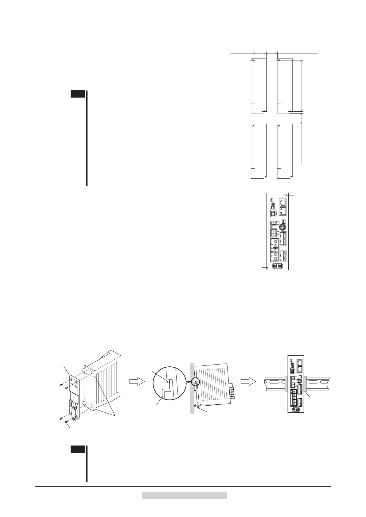
The driver is designed so that heat is dissipated via air convection
and conduction through the enclosure. Install the driver to a at
metal plate oering excellent vibration resistance.
When two or more drivers are to be installed side by side, provide
20 mm (0.79 in.) and 25 mm (0.98 in.) clearances in the horizontal
and vertical directions, respectively.
Note
•Install the driver in an enclosure whose pollution
degree is 2 or above or protection class is IP54 or
better.
•Be sure to install the driver vertically (in vertical
position) shown in the gure. Do not block the
radiation openings.
•Do not install any equipment that generates a large
amount of heat or noise near the driver.
•If the ambient temperature of the driver exceeds the
upper limit of the operating ambient temperature,
revise the ventilation condition or forcibly cool the
area around the driver using a fan in order to keep
within the operating ambient temperature.
Installation
150 (5.91)
25 (0.98) or more
Installing with screws
Install the driver vertically (in vertical position) and secure the driver
(at the back)
through the mounting holes using two screws (M4: not supplied).
Mounting to DIN rail
When mounting the driver to a DIN rail, use a separately sold DIN rail mounting plate (model number:
attach it to a 35 mm (1.38 in.) wide DIN rail.
1. Attach the DIN rail mounting plate to the back of the driver using the screws supplied with the plate.
Tightening torque: 0.3 to 0.4 N
m (2.6 to 3.5 lb-in)
·
2. Pull the DIN lever down, engage the upper tab of the DIN rail mounting plate over the DIN rail, and
push the DIN lever until it locks in place.
3. Fix the driver with the end plate (not suupplied).
Tab
PADP03
) and
Mounting screws
Note
DIN rail
Mounting holes
(M3, four locations)
DIN lever
•Do not use the mounting holes for the DIN rail mounting plate for any purpose other than
securing the DIN rail mounting plate.
•Be sure to use the supplied screws when securing the DIN rail mounting plate. The use of
screws that would penetrate 3 mm (0.12 in.) or more through the surface of the driver may
cause damage to the driver.
2 Installation and connection
−29−
Page 30
Installation
DIN lever
0.45 N·m (3.9 lb-in)
Variable resistor
Va
Dial
• Mounting hole dimension
(Ø0.165 in.)
0
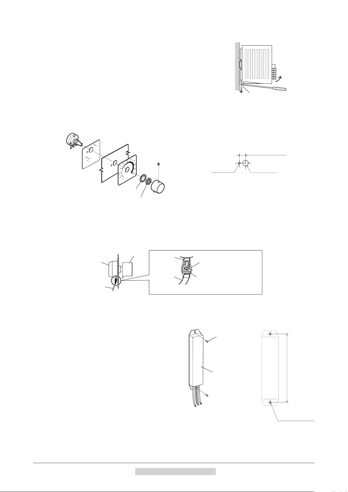
Removing from DIN rail
Pull the DIN lever down until it locks using a at tip screwdriver, and lift the
bottom of the driver to remove it from the rail.
Use force of about 10 to 20 N (2.2 to 4.5 lb.) to pull the DIN lever to lock it.
Excessive force may damage the DIN lever.
1.10 Installing the external potentiometer (supplied)
Install the external potentiometer as shown below.
Insulation
sheet
Toothed washer
Mounting plate
Dial plate
Setscrew (M4)
Tightening torque:
0.4 N·m (3.5 lb-in)
Dial
Nut
Tightening torque:
• Reference mounting hole dimensions
Ø3 (Ø0.12)
[Unit: mm (in.)]
7.5±
0.4 (0.30±0.02)
Ø10 (Ø0.39)
Soldering the variable resister terminal and the lead wires
Cover a heat-shrinkable tube over the soldered part to insulate.
Soldering condition: 235 °C (455 °F), less than 5 sec.
riable resistor
Lead wire
Terminal
Lead wire
Heat-shrinkable tube
Solder (Pass the lead wire
through the terminal hole and
give it two or three turns.)
1.11 Installing the regeneration unit (accessory)
Install the regeneration unit
where heat dissipation capacity equivalent to a level
achieved with a heat sink [made of aluminum alloy,
350×350×3 mm (13.78×13.78×0.12 in.)] is ensured.
Secure it on a smooth metal plate oering high heat
conductivity, using two screws (M4, not supplied).
−30−
EPRC-400P
2 Installation and connection
in a location
Screw (M4)
Regeneration unit
EPRC-400P
165 mm (6.50 in.)
+0.3
Ø4.2 mm
0
+0.012
Page 31

2 Connection
3
8
This chapter explains how to connect the driver and motor, I/O signals, and power supply, as well as the grounding
method.
2.1 Connection example
The following gure is a connection example when an electromagnetic brake motor is used.
Grounding
Motor
cable
Protective Earth Terminal
Be sure to ground.
("2.3 Grounding" on p.32)
Main power supply
Main power supply
Three-phase 200-240 V
∗ Electromagnetic brake type only
Single-phase 100-120 V
Single-phase 200-240 V
Motor signal connector
Connect to CN4
Connection cable
Electromagnetic brake
Motor power connector
connector
Connect to CN1
Connect to CN2
Protective Earth Terminal
Be sure to ground.
("2.3 Grounding" on p.32)
Connection
Input signals
Connect to CN5 pin No.1 to 8
24 VDC
∗
External potentiometer or
External DC voltage
Connect to CN6 pin No.1 to
Input signal common (0 V)
Connect to CN6 pin No.4
Output signals
Grounding
Connect to CN6 pin No.5 to
power supply
24 VDC±5%
1.0 A or more
Note
•Have the connector plugged in securely. Insecure connections may cause malfunction or damage to the motor
or driver.
•When unplugging the connector, do so while pressing the latches on the connector.
When cycle the power or plugging/unplugging the connector, turn o the power and wait for the CHARGE LED
•
to turn o before doing so. Residual voltage may cause electric shock.
•Do not wire the power supply cable of the driver in the same cable duct with other power lines or motor cables.
Doing so may cause malfunction due to noise.
When installing the motor to a moving part, use an accessory exible cable oering excellent exibility. For the
•
exible motor cable, refer to p.160.
2 Installation and connection
−31−
Page 32

Connection
7.2 (0.28) or less
6.2 (0.24) or les
after crimping
Ø3.6 (0.14) or more
Unit: mm (in.)
Grounding
Protective Earth
Te
9.5 (0.37) or less
Unit: mm (in.)
Protective Earth
Be sure to ground either of
the Protective Earth
2.2 Connecting the power supply
Connect the power cable to the main power supply input terminals (TB1) on the driver.
The product does not come with a power cable. It must be supplied by the user.
Power supply input Connecting method
Single-phase 100-120 V Connect the live side to terminal L, and the neutral side to terminal N.
Single-phase 200-240 V Connect the live side to terminal L1, and the neutral side to terminal L2.
Three-phase 200-240 V Connect the R, S and T phase lines to the L1, L2 and L3 terminals, respectively.
Power connection terminal and cable
•Applicable crimp terminal: Round crimp terminal with
insulation cover
Thread size of terminal: M3.5
•
Tightening torque: 1.0 N
•
•Applicable lead wire: AWG18 to 14 (0.75 to 2.0 mm
•Conductive material: Use only copper wire.
Circuit breaker
Be sure to connect a circuit breaker to the power line of the driver to protect the primary circuit.
•Rated current of protective device: Single-phase input 10 A, three-phase input 5 A
Circuit breaker: Mitsubishi Electric Corporation NF30
•
m (8.8 lb-in)
·
s
3.8 (0.15)
2
)
or less
2.3 Grounding
Be sure to ground using the Protective Earth Terminal of the motor and the Protective Earth Terminal of the driver.
Note
Be sure to ground the motor and driver. Failure to do so may result in electric shock or damage to
the product. Static electricity may cause damage to the product if the Protective Earth Terminals
are not grounded.
Motor
Connect the Protective Earth Terminal on the motor to the ground near the motor.
Minimize the wiring length of the ground cable.
Ground terminal and cable
•Applicable crimp terminal: Round crimp terminal with insulation cover
Thread size of terminal: M4
•
Tightening torque: 0.8 to 1.0 N·m (7.0 to 8.8 lb-in)
•
•Applicable lead wire: AWG18 to 14 (0.75 to 2.0 mm
Driver
Either of the two Protective Earth Terminals can be used for grounding the driver.
The terminal that is not grounded can be used as a spare terminal. Use the spare
terminal according to your specic need, such as connecting it to the motor in
order to ground the motor. Do not share the Protective Earth Terminal with a
welder or any other power equipment. When grounding the Protective Earth
Terminal, secure the grounding point near the driver.
•Applicable crimp terminal: Round crimp terminal with insulation cover
Thread size of terminal: M4
•
Tightening torque: 1.2 N
•
•Applicable lead wire: AWG18 to 14 (0.75 to 2.0 mm
Ø4.1 (0.16) or more
4.8 (0.19) or less
m (10.6 lb-in)
·
2
)
rminal
Grounding
Terminal
2
)
Terminals.
−32−
Precautions about static electricity
Static electricity may cause the driver to malfunction or suer damaged.
Be sure to ground the motor and driver to prevent them from being damaged by static electricity.
2 Installation and connection
Page 33

2.4 Connecting the motor and driver
∗ Electromagnetic brake type only
Position to hold the connector
Connect the motor power connector to the CN2, and the motor signal connector to the CN4 on the driver.
When using an electromagnetic brake type motor, also connect the electromagnetic brake connector to the CN1.
When extending the connection distance between the motor and driver, use the connection cable (supplied or
accessory).
Motor signal connector
Connect to CN4
Connection cableMotor cable
Connection
Note
Have the connector plugged in securely. Insecure connector connection may cause malfunction or
Electromagnetic brake
connector
Connect to CN1
Motor power connector
Connect to CN2
∗
damage to the motor or driver.
Notes about connector connection
Note
When inserting connectors or pulling out connectors, be sure
to do with holding the connector bodies. Doing with holding the
cables may cause a connection failure.
When inserting the connector
●
Hold the connector bodies, and insert in straight securely.
Inserting the connector in an inclined state may result in damage to terminals or a connection failure.
When pulling out the connector
●
Pull out the connector in straight while releasing the lock part of the connector.
Pulling out the connector with holding the cable (lead wire) may result in damage to the connector.
•Pin assignment of motor power connector
Pin No. Color Lead size
1 Blue AWG18
2 − −
3 − Drain (AWG24 or equivalent)
4 Purple
5 Gray
6 − −
AWG18
Housing: 5557-06R-210 (Molex)
Terminal: 5556T (Molex)
6
3
5
2
4
1
•Pin assignment of motor signal connector •Pin assignment of electromagnetic brake
connector
Pin No. Color Lead size
1 − − 1 Black
2 Green
3 Yellow
4 Brown
5 Red
6 Orange
AWG26
3
6
2
5
1
4
Housing: 43025-0600
(Molex)
Terminal: 43030-0004
(Molex)
Pin No. Color Lead size
2 White
Housing: 5557-02R-210 (Molex)
Terminal: 5556T (Molex)
AWG24
21
2 Installation and connection
−33−
Page 34

Connection
power supply
-
the button of the orange color with
1
+
-
8
•
•
•
2.5 Connecting the 24 VDC power supply
The 24 VDC power supply is for the control circuit of the driver.
Be sure to connect a power supply which voltage is 24 VDC −15% to
+20% and current is 1 A or more, to the CN5.
24 VDC
+
Note
•When connecting the 24 VDC power supply, check the indication of the driver case and pay
attention to the polarity of the power supply. Reverse-polarity connection may cause damage to
the driver.
When cycling the 24 VDC power, turn o the power and wait for the PWR/ALM LED to turn o.
•
2.6 Selecting the input signal power supply
Select the input signal power supply (built-in power
supply or external power supply) to be used.
The driver comes with a built-in power supply. To control
the operation using relays and switches, set the SW3-No.3
of the function setting switch1 to the ON side to select the
built-in power supply.
Factory setting: OFF (an external power supply is used)
Note
The built-in power supply cannot be used with the source logic. If the source logic is used, do not
turn the external voltage selector switch to the ON side.
2.7 Connecting the I/O signals
Connect the input signals to the CN5, and connect the analog external speed setting input signals and output signals to
the CN6.
•Applicable lead wire: AWG26 to 20 (0.14 to 0.5 mm
•Length of the insulation cover which can be peeled: 8 mm (0.31 in.)
Button of the orange color
Insert the lead wire while pushing
2
)
SW3-No.3
ON: Using the built-in
power supply
OFF: Using an external
power supply
8 mm (0.31 in.)
a screwdriver.
CN5 pin assignment
Pin No Name Description
1 IN0 Input terminal 0 [FWD]
2 IN1 Input terminal 1 [REV]
3 IN2 Input terminal 2 [STOP-MODE]
4 IN3 Input terminal 3 [M0]
5 IN4 Input terminal 4 [ALARM-RESET]
6 IN5 Input terminal 5 [MB-FREE]
7 IN6 Input terminal 6 [TH]
8 IN-COM0 Input signal common
− −
Power supply GND/
Input signal common (0 V)
+ − 24 VDC power supply
* The signal in brackets [ ] is a function that is assigned at the time of shipment. The assignments can be changed using the
OPX-2A
or
MEXE02
, or via RS-485 communication.
∗
•
•
−34−
2 Installation and connection
Page 35

CN6 pin assignment
1
8
•
•
•
CN5
Pin No.
reinforced insulation
CN6
Pin No.
Pin No.
Inductive load
External controle
Pin No Name Description
1 VH
Analog external speed setting input2 VM
3 VL
1
∗
4 IN-COM1 Input signal common (0 V)
5 OUT0+ Output terminal 0 (+) [SPEED-OUT]
6 OUT0− Output terminal 0 (−) [SPEED-OUT]
7 OUT1+ Output terminal 1 (+) [ALARM-OUT1]
8 OUT1− Output terminal 1 (−) [ALARM-OUT1]
*1 The VL input is connected to IN-COM1 inside the driver.
*2 The signal in brackets [ ] is a function that is assigned at the time of shipment. The assignments can be changed using
the
OPX-2A
or
MEXE02
, or via RS-485 communication.
2
∗
•
•
Input signal circuit
All input signals of the driver are photocoupler inputs.
When an external power supply is used: 24 VDC –15 to +20%,
100 mA or more
1 to 7
8
5.1 kΩ
820 Ω
Photo-coupler of
Connection
Output signal circuit
All output signals of the driver are photocoupler/open-collector
outputs. The ON voltage of the output circuit is 1.6 VDC maximum.
When driving each element using the output signal circuit, give
consideration to this ON voltage.
4.5 to 30 VDC, 40 mA or less (For the SPEED-OUT output, supply at
least 5 mA of current.)
Note
•Always connect a current-limiting resistor. If the power supply voltage is connected to the
output circuit directly without connecting a current-limiting resistor in between, the driver will be
damaged.
•When connecting a relay (inductive load), etc., to detect alarm
outputs, use a relay with built-in ywheel diode, or provide a
y-back voltage control measure based on diode, etc., for the
inductive load.
Using a controller with a built-in clamp diode
If a controller with a built-in clamp diode is used, a leakage
path may form and cause the motor to operate even when
the controller power is o, as long as the driver power is on.
Since the power capacity of the controller is dierent from
that of the driver, the motor may operate when the controller
and driver powers are turned on or o simultaneously.
When powering down, turn o the driver power rst,
followed by the controller power. When powering up, turn on
the controller power rst, followed by the driver power.
quipment Driver
5, 7
6, 8
CN6
5, 7
VCC +24 V
CN5
1 to 7
-
0 V
Flywheel
diode
0 V
2 Installation and connection
−35−
Page 36

Connection
Master controller Driver
Connection example with I/O signal circuit
•Sink logic circuit
CN5
1
2
3
4
5
24 VDC
0 V
30 VDC or less
0 V
R
R0
0
24 VDC
0 V
40 mA or less
40 mA or less
6
7
8
+
CN6
5
6
7
8
5.1 kΩ
5.1 kΩ
5.1 kΩ
5.1 kΩ
5.1 kΩ
5.1 kΩ
5.1 kΩ
820 Ω
820 Ω
820 Ω
820 Ω
820 Ω
820 Ω
820 Ω
Note
•Keep the output signal to 30 VDC or less.
•Be sure to connect the current-limiting resistor R0 and keep the current to 40 mA or less.
−36−
2 Installation and connection
Page 37

•Source logic circuit
Master controller Driver
CN6
External DC
CN6
24 VDC
Connection
CN5
1
2
3
4
5
0 V
30 VDC or less
40 mA or less
40 mA or less
24 VDC
0 V
R0
R0
6
7
8
+
CN6
5
6
7
8
5.1 kΩ
5.1 kΩ
5.1 kΩ
5.1 kΩ
5.1 kΩ
5.1 kΩ
5.1 kΩ
820 Ω
820 Ω
820 Ω
820 Ω
820 Ω
820 Ω
820 Ω
0 V
Note
•Keep the output signal to 30 VDC or less.
•Be sure to connect the current-limiting resistor R0 and keep the current to 40 mA or less.
2.8 Connecting an external speed setter
The rotation speed can be set using an external potentiometer (supplied) or external DC voltage.
Refer to p.66 for setting method.
•Using an external potentiometer
Connect the supplied external potentiometer to the pin Nos.1
to 3 of CN6 of the driver. Use the supplied signal wire for this
connection.
Connect the shield wire of the signal wire to the VL input
terminal. Make sure the shield wire does not contact other
terminals.
•Using an external DC voltage
For the external voltage, use a DC power supply (0 to 10 VDC)
with reinforced insulation on both the primary side and secondary
side, and connect it to the pin Nos. 2 and 3 of CN6 of the driver.
The input impedance between the VM input and VL input is
approximately 30 k
inside the driver.
. The VL input is connected to IN-COM1
Ω
External potentiometer
1 VH input
2 VM input
3 VL input
2 VM input
3 VL input
Yellow Red
Red
power supply
0 to 10 VDC
1 mA or more
Yellow
WhiteWhite
123
Note
Be sure to set the external DC voltage to 10 VDC or less. When connecting the external DC
power supply, make sure the polarities are correct. If the polarities are reversed, the driver may be
damaged.
2 Installation and connection
−37−
Page 38

Connection
OPX-2A cable or supplied
RS-485 communication
Drivers can be linked.
0 V
∗
0 V
∗
5 V
1
8
•
•
•
2.9 Connecting the data setter
Connect
the
MEXE02
OPX-2A
cable or supplied cable with
to CN3 on the driver.
The data edit connector (CN3), I/O signal connectors (CN5/CN6) and RS-485
communication connectors (CN7/CN8) are not insulated. When grounding the
positive terminal of the power supply, do not connect any equipment (PC, etc.)
whose negative terminal is grounded. Doing so may cause the these equipment
and driver to short, damaging both.
2.10 Connecting the RS-485 communication cable
Connect this cable when controlling the product via RS-485 communication. Connect the RS-485 communication
cable to the CN7 or CN8 on the driver.
The vacant connector can be used to connect a dierent driver. A driver link cable is available as an accessory (sold
separately). See p.160. A commercial LAN cable can be also used to link drivers.
cable with the MEXE02
connectors (CN7/CN8)
CN7/CN8 pin assignment
Pin No Name Description
1 N.C. Not used
2 GND GND
3 TR+ RS-485 communication signal (+)
4 N.C.
5 N.C.
6 TR− RS-485 communication signal (−)
7 N.C.
8 N.C.
Not used
Not used
2 GND
3 TR+
6 TR
-
2 GND
3 TR+
-
6 TR
* The GND line is used in common with 24 VDC power
supply input terminal (CN5).
SW3-No.4
100 kΩ
120 Ω
100 kΩ
•
•
−38−
2 Installation and connection
Page 39

2.11 Test operation
Regeneration unit
CN5 and CN6
Once a main power supply and 24 VDC power supply are connected, the connection status can be checked by driving
the motor tentatively without setting the data.
1. Turn on the main power supply and 24 VDC power supply after completing the wiring.
2. Turn the test operation mode switch (SW2-No.1)
ON.
3. Check that the motor rotates at low speed
(100 r/min) in the forward direction.
If the motor did not rotate or malfunction could be seen,
check the wiring after turning o the power.
(If the rotation direction has been changed by the
rotates according to the setting.)
4. Turn the test operation mode switch OFF.
The motor stops.
Note
If the FWD input or REV input is turned ON while the motor rotates in test operation, the motor
will stop. (A warning or alarm signal is not output.) To reset this condition, turn all of test operation
mode switch, FWD input and REV input OFF. The motor will be able to operate after turning all of
them OFF.
2.12 Connecting the regeneration unit
If vertical drive (gravitational operation) such as elevator applications is performed or if sudden start-stop operation
of a large inertial load is repeated frequently, connect the regeneration unit
Install the regeneration unit in a location where heat dissipation capacity equivalent to a level achieved with a heat
sink [made of aluminum alloy, 350×350×3 mm (13.78×13.78×0.12 in.)] is ensured.
OPX-2A
Test operation mode
switch (SW2-No.1)
or
MEXE02
, or via RS-485 communication, the motor
EPRC-400P
Connection
.
Connecting method
The wiring of the regeneration unit to the driver I/O terminals varies depending on the connecting methods.
Refer to p.41, 42, 43 for connecting method.
Connect the regeneration unit before turning on the main power and 24 VDC power. The regeneration unit does not
perform its control function if connected after the main power and 24 VDC power has been turned on.
Regenerative current ows through the two thick lead wires (AWG18: 0.75 mm
•
them to the RG1 and RG2 terminals of the TB1. The applicable crimp terminal is the same as the one used to
connect the power supply. Refer to p.32.
•The two thin lead wires (AWG22: 0.3 mm
2
) of the regeneration unit are thermostat outputs. Connect them to CN5
and CN6. Refer to p.34 for connecting method.
EPRC-400P
150 °C (302 °F)
[N.C.]
R: 400 Ω
AWG22
AWG18
Connect to RG1 and
RG2 terminals on TB1
TH input
IN-COM1
Connect to
2
) of the regeneration unit. Connect
Note
•If the current consumption of the regeneration unit exceeds the allowable level, the thermostat
will be triggered and a regeneration unit overheat alarm will generate. If a regeneration unit
overheat alarm generates, turn o the power and check the content of the error.
•If an external power supply is used for the power supply of input signals, turn on the external
power supply before turning on the driver main power supply.
2 Installation and connection
−39−
Page 40

Connection
Regenerationunitspecications
Model
Continuous regenerative power 100 W
Resistance 400
Operating temperature of
thermostat
Electrical rating of thermostat 120 VAC 4 A, 30 VDC 4 A (minimum current: 5 mA)
EPRC-400P
Ω
Operation: Opens at 150±7 °C (302±45 °F)
Reset: Closes at 145±12 °C (293±54 °F) (normally closed)
−40−
2 Installation and connection
Page 41

2.13 Connection diagram (example)
Driver
Each connection diagram (example) is for the electromagnetic brake type. In the case of the standard type, there are
no connection for the electromagnetic brake and no connection/input for the MB-FREE input signal.
To use the built-in power supply, set the SW3-No.3 of the
function setting switch switch1 to the ON side.
The factory setting is OFF (an external power supply is
used). To use an external power supply, the factory setting
need not be changed.
Sink logic
•Using the built-in power supply
This is a connection example that the power supply is single-phase 100-120 VAC, the rotation speed is set using an
external potentiometer or external DC voltage, and the motor is operated with relays, switches and other contact
switches. For the SPEED-OUT output, supply at least 5 mA of current.
Connection
SW3-No.3
ON: Using the built-in
power supply
OFF: Using an external
power supply
Circuit breaker
Power supply
connection
L
N
Grounding the driver
Be sure to ground.
R:400 Ω
N.C.
150 °C
(302 °F)
Regeneration unit
RS-485 communication
connection
Data setter connection
Input signal connection
Control input 0 [FWD]
Control input 1 [REV]
Control input 2 [STOP-MODE]
Control input 3 [M0]
Control input 4 [ALARM-RESET]
Control input 5 [MB-FREE]
DC power
supply
24 VDC
-
15% to +20%
Control input 6 [TH]
connection
IN-COM0
POWER
L
N
NC
RG1
RG2
CN5
8
1
2
3
4
5
6
+
7
+24 V
Main circuit
Control circuit
command
Motor connector
Electromagnetic
brake connector
Motor signal
connector
+5.3 V
CN6
Speed
voltage
0 V
CN6
CN6
0 V
Motor connection
Motor
Grounding the motor
Be sure to ground.
Setting by the external
potentiometer
or external DC voltage
1
2
3
VH
VM
VL
Output signal connection
4.5 to 30.0 VDC
40 mA or less
Control output 0
[SPEED-OUT]
5
6
7
8
∗
∗
Control output 1
[ALARM-OUT1]
Input signal connection
4
IN-COM1
External
potentiometer
(20 kΩ 1/4 W)
Within 10 V
Shielded cable
Grounding
* Recommended resistance 24 VDC: 680 Ω to 4.7 kΩ (2 W) 5 VDC: 150 Ω to 1.0 kΩ (0.5 W)
Note
Be sure to ground the motor and driver. Failure to do so may result in electric shock or damage to the product.
Static electricity may cause damage to the product if the Protective Earth Terminals are not grounded.
2 Installation and connection
−41−
Page 42

Connection
Driver
•Using an external power supply
This is a connection example that the power supply is single-phase 100-120 VAC, the rotation speed is set using an
external potentiometer or external DC voltage, and the motor is operated with sequence connection of transistor type.
For the SPEED-OUT output, supply at least 5 mA of current.
Circuit breaker
Power supply
connection
L
N
Grounding the driver
Be sure to ground.
R:400 Ω
N.C.
150 °C
(302 °F)
Regeneration unit
connection
RS-485 communication
connection
Data setter connection
Input signal connection
Control input 0
Control input 1
Control input 2
[STOP-MODE]
Control input 3
Control input 4
[ALARM-RESET]
Control input 5
[MB-FREE]
IN-COM0
[FWD]
[REV]
[M0]
∗1
POWER
L
N
NC
RG1
RG2
CN5
8
1
2
3
4
5
6
Main circuit
Control circuit
command
Motor connector
Electromagnetic
brake connector
Motor signal
connector
+5.3 V
CN6
Speed
voltage
0 V
CN6
CN6
0 V
Motor connection
Motor
Grounding the motor
Be sure to ground.
Setting by the external
potentiometer
or external DC voltage
1
2
3
VH
VM
VL
Output signal connection
4.5 to 30.0 VDC
40 mA or less
Control output 0
[SPEED-OUT]
5
6
7
8
∗2
∗2
Control output 1
[ALARM-OUT1]
Input signal connection
4
IN-COM1 ∗3
External
potentiometer
(20 kΩ 1/4 W)
Within 10 V
DC power
*1 Turn on the external power supply before turning on the driver main power supply.
*2 Recommended resistance 24 VDC: 680 Ω to 4.7 kΩ (2 W) 5 VDC: 150 Ω to 1.0 kΩ (0.5 W)
*3 When connecting one of the lead wires of the thermostat output to the IN-COM1, connect it in common with a GND of the external power supply.
Note
24 VDC
-
supply
15% to +20%
Control input 6 [TH]
Be sure to ground the motor and driver. Failure to do so may result in electric shock or damage to the product.
+
7
Shielded cable
Grounding
Static electricity may cause damage to the product if the Protective Earth Terminals are not grounded.
−42−
2 Installation and connection
Page 43

Connection
Driver
Source logic
This is a connection example that the power supply is single-phase 100-120 VAC, the rotation speed is set using an
external potentiometer or external DC voltage, and the motor is operated with sequence connection of transistor type.
For the SPEED-OUT output, supply at least 5 mA of current.
Circuit breaker
Power supply
connection
L
N
Grounding the driver
Be sure to ground.
R:400 Ω
Regeneration unit
N.C.
150 °C
(302 °F)
connection
RS-485 communication
connection
Data setter connection
Input signal connection
Control input 0
Control input 1
Control input 2
[STOP-MODE]
Control input 3
Control input 4
[ALARM-RESET]
Control input 5
[MB-FREE]
[FWD]
[REV]
[M0]
POWER
L
N
NC
Main circuit
Motor connector
Electromagnetic
brake connector
Motor connection
Motor
Grounding the motor
RG1
RG2
Control circuit
command
+5.3 V
Speed
voltage
0 V
Motor signal
connector
CN6
1
2
3
Be sure to ground.
Setting by the external
potentiometer
or external DC voltage
VH
VM
VL
External
potentiometer
(20 kΩ 1/4 W)
Within 10 V
Output signal connection
4.5 to 30.0 VDC
40 mA or less
CN6
5
∗1
CN5
1
2
3
4
5
6
0 V
6
7
8
CN6
4
Control output 0
[SPEED-OUT]
∗2
∗2
Control output 1
[ALARM-OUT1]
IN-COM1 ∗3
IN-COM0
DC power
*1 Turn on the external power supply before turning on the driver main power supply.
*2 Recommended resistance 24 VDC: 680 Ω to 4.7 kΩ (2 W) 5 VDC: 150 Ω to 1.0 kΩ (0.5 W)
*3 When connecting one of the lead wires of the thermostat output to the IN-COM1, connect it in common with a GND of the external power supply.
Note
24 VDC
-
supply
15% to +20%
Control input 6 [TH]
Be sure to ground the motor and driver. Failure to do so may result in electric shock or damage to the product.
8
+
7
Shielded cable
Grounding
Static electricity may cause damage to the product if the Protective Earth Terminals are not grounded.
2 Installation and connection
−43−
Page 44

Explanation of I/O signals
3 Explanation of I/O signals
In this manual, I/O signals are described as follows.
Direct I/O: I/O signals accessed via input signal connector (CN5) and I/O signal connector (CN6)
•
Network I/O: I/O signals accessed via RS-485 communication
•
Set the following parameters using any of the
3.1 Assignment of direct I/O
Assignment to the input terminals
The input signals shown below can be assigned to the input terminals IN0 to IN6 of CN5 by setting parameters.
For details on input signals, refer to p.50.
Input terminal Initial value Input terminal Initial value
IN0 1: FWD IN4 24: ALARM-RESET
IN1 2: REV IN5 20: MB-FREE
IN2 19: STOP-MODE IN6 22: TH
IN3 48: M0
Assignment No. Signal name Function
0 Not used Set when the input terminal is not used.
1 FWD Rotate the motor in the forward direction.
2 REV Rotate the motor in the reverse direction.
19 STOP-MODE Select instantaneous stop or deceleration stop.
20 MB-FREE Release the electromagnetic brake.
21 EXT-ERROR
22 TH
24 ALARM-RESET Reset of the present alarm.
27 HMI
32 R0
33 R1
34 R2
35 R3
36 R4
37 R5
38 R6
39 R7
40 R8
41 R9
42 R10
43 R11
44 R12
45 R13
46 R14
47 R15
48 M0
49 M1
50 M2
51 M3
54 TL Disable the torque limiting. (normally closed).
OPX-2A, MEXE02
Stop the motor (normally closed).
Release of the function limitation of the
MEXE02
General signals
Use these signals when controlling the system via
RS-485 communication.
Select the operation data No. using these four bits.
(normally closed).
or RS-485 communication.
OPX-2A
or
−44−
2 Installation and connection
Page 45

Related parameters
Parameter name Description Initial value
IN0 function select
IN1 function select 2: REV
IN2 function select 19: STOP-MODE
IN3 function select 48: M0
IN4 function select 24: ALARM-RESET
IN5 function select 20: MB-FREE
IN6 function select 22: TH
Assigns the input signals to the input
terminal IN0 to IN6.
See the table on the previous page for the
assignment number and corresponding
signal.
1: FWD
Explanation of I/O signals
Note
•Do not assign the same input signal to multiple input terminals. When the same input signal
is assigned to multiple input terminals, the function will be executed if any of the terminals
becomes active.
•The ALARM-RESET input will be executed when turning from ON to OFF.
•When the HMI input and TL input are not assigned to the input terminals, these inputs will be
always set to ON. When assigning them to multiple terminals (including direct I/O and network
I/O), the function will be executed when all terminals are set to ON.
Changing the logic level setting of input signals
You can change the logic level setting for input terminals IN0 to IN6 using the parameter.
Related parameters
Parameter name Description Initial value
IN0 contact conguration
IN1 contact conguration
IN2 contact conguration
IN3 contact conguration
IN4 contact conguration
IN5 contact conguration
IN6 contact conguration
Changes the logic level setting for the
input terminal IN0 to IN6.
0: Normally open
1: Normally closed
0
2 Installation and connection
−45−
Page 46

Explanation of I/O signals
Assignment to the output terminals
The output signals shown below can be assigned to the output terminals OUT0 and OUT1 of CN6 by setting
parameters. For details on output signals, refer to p.52.
Output terminal Initial value
OUT0 85: SPEED-OUT
OUT1 65: ALARM-OUT1
Assignment No. Signal name Function
0 Not used Set when the output terminal is not used.
1 FWD_R Output in response to the FWD input.
2 REV_R Output in response to the RVS input.
19 STOP-MODE_R Output in response to the STOP-MODE input.
20 MB-FREE_R Output in response to the MB-FREE input.
27 HMI_R Output in response to the HMI input.
32 R0
33 R1
34 R2
35 R3
36 R4
37 R5
38 R6
39 R7
40 R8
41 R9
42 R10
43 R11
44 R12
45 R13
46 R14
47 R15
48 M0_R
49 M1_R
50 M2_R
51 M3_R
54 TL_R Output in response to the TL input.
65 ALARM_OUT1 Output the alarm status of the driver (normally closed).
66 WNG Output the warning status of the driver.
68 MOVE Output while the motor operates.
71 TLC Output when the motor torque reaches the torque limiting value.
77 VA Output when the motor speed reaches the setting value.
80 S-BSY Output when the driver is in internal processing state.
81 ALARM-OUT2
82 MPS Output the ON-OFF state of the main power supply.
84 DIR Output the rotation direction of motor shaft.
85 SPEED-OUT 30 pulses are output with each revolution of the motor output shaft.
Output the status of the general signals R0 to R15.
Output in response to the M0 to M3 inputs.
Output when the overload warning detection level is exceeded.
Output when the overload alarm generates. (normally closed)
−46−
Related parameters
Parameter name Description Initial value
OUT0 function select
OUT1 function select 65: ALARM-OUT1
Assigns the output signals to the output terminals OUT0 and
OUT1. See the table above for the assignment number and
corresponding signal.
85: SPEED-OUT
2 Installation and connection
Page 47

3.2 Assignment of network I/O
Assign the I/O function via RS-485 communication.
Assignment of input signals
The input signals shown below can be assigned to the NET-IN0 to NET-IN15 of network I/O by setting parameters.
See each command description for the assignments of the NET-IN0 to NET-IN15.
Assignment No. Signal name Function Setting range
0 Not used Set when the input terminal is not used. −
1 FWD Rotate the motor to FWD direction.
2 REV Rotate the motor to REV direction.
19 STOP-MODE Select instantaneous stop or deceleration stop.
20 MB-FREE Release the electromagnetic brake.
27 HMI
32 R0
33 R1
34 R2
35 R3
36 R4
37 R5
38 R6
39 R7
40 R8
41 R9
42 R10
43 R11
44 R12
45 R13
46 R14
47 R15
48 M0
49 M1
50 M2
51 M3
54 TL Disable the torque limiting. (normally closed).
Release of the function limitation of the
OPX-2A
General signals
Use these signals when controlling the system
via RS-485 communication.
Select the operation data No. using these four
bits.
MEXE02
or
(normally closed).
Explanation of I/O signals
0: Stop
1: Operation
0: Instantaneous stop
1: Deceleration stop
0: Electromagnetic brake
hold
1: Electromagnetic brake
release
0: Function limitation
1: Function limitation
release
0: OFF
1: ON
0: OFF
1: ON
(Operation data No.0 to
15 can be selected.)
0: Torque limiting disable
1: Torque limiting enable
2 Installation and connection
−47−
Page 48

Explanation of I/O signals
Related parameters
Parameter name Description Initial value
NET-IN0 function select
NET-IN1 function select 49: M1
NET-IN2 function select 50: M2
NET-IN3 function select 1: FWD
NET-IN4 function select 2: REV
NET-IN5 function select 19: STOP-MODE
NET-IN6 function select 20: MB-FREE
NET-IN7 function select
NET-IN8 function select
NET-IN9 function select
NET-IN10 function select
NET-IN11 function select
NET-IN12 function select
NET-IN13 function select
NET-IN14 function select
NET-IN15 function select
48: M0
Assigns the input signals to the NETIN0 to NET-IN15.
See the table on the previous page
for the assignment number and
corresponding signal.
0: Not used
Note
•Do not assign the same input signal to multiple input terminals. When the same input signal
is assigned to multiple input terminals, the function will be executed if any of the terminals
becomes active.
•When the HMI input and TL input are not assigned to the input terminals, these inputs will be
always set to ON. When assigning them to multiple terminals (including direct I/O and network
I/O), the function will be executed when all terminals are set to ON.
−48−
2 Installation and connection
Page 49

Explanation of I/O signals
Assignment to the output terminals
The output signals shown below can be assigned to the NET-OUT0 to NET-OUT15 of network I/O by setting
parameters. See each command description for the assignments of the NET-OUT0 to NET-OUT15.
Assignment No. Signal name Function Data read
0 Not used Set when the output terminal is not used.
1 FWD_R Output in response to the FWD input.
2 RVS_R Output in response to the RVS input.
19 STOP-MODE_R
20 MB-FREE_R Output in response to the MB-FREE input.
27 HMI_R Output in response to the HMI input.
32 R0
33 R1
34 R2
35 R3
36 R4
37 R5
38 R6
39 R7
40 R8
41 R9
42 R10
43 R11
44 R12
45 R13
46 R14
47 R15
48 M0_R
49 M1_R
50 M2_R
51 M3_R
54 TL_R Output in response to the TL input.
65 ALARM-OUT1
66 WNG Output the warning status of the driver.
68 MOVE Output while the motor operates.
71 TLC
77 VA
80 S-BSY
81 ALARM-OUT2
82 MPS
84 DIR Output the rotation direction of motor shaft.
Output in response to the STOP-MODE
input.
Output the status of the general signals R0
to R15.
Output in response to the M0 to M3 inputs.
Output the alarm status of the driver
(normally closed).
Output when the motor torque reaches the
torque limiting value.
Output when the motor speed reaches the
setting value.
Output when the driver is in internal
processing state.
Output when the overload warning detection
level is exceeded.
Output when the overload alarm generates.
(normally closed)
Output the ON-OFF state of the main power
supply.
0: OFF
1: ON
0: Alarm not present
1: Alarm present
0: Warning not present
1: Warning present
0: Motor stopped
1: Motor operating
0: No torque limiting
1: In torque limiting
operation
0: Speed not attained
1: Speed attainment
0: OFF
1: ON
0: Normal operation
1: In overload operation
0: OFF
1: ON
0: REV direction
1: FWD direction
2 Installation and connection
−49−
Page 50

Explanation of I/O signals
Related parameters
NET-OUT0 function select
NET-OUT1 function select 49: M1_R
NET-OUT2 function select 50: M2_R
NET-OUT3 function select 1: FWD_R
NET-OUT4 function select 2: REV_R
NET-OUT5 function select 19: STOP-MODE_R
NET-OUT6 function select 66: WNG
NET-OUT7 function select 65: ALARM-OUT1
NET-OUT8 function select 80: S-BSY
NET-OUT9 function select
NET-OUT11 function select
NET-OUT12 function select 81: ALARM-OUT2
NET-OUT13 function select 68: MOVE
NET-OUT14 function select 77: VA
NET-OUT15 function select 71: TLC
Parameter name Description Initial value
48: M0_R
Assigns the output signal to the NETOUT0 to NET-OUT15.
See the table on the previous page
for the assignment number and
corresponding signal.
0: Not usedNET-OUT10 function select
3.3 Input signals
The signal state represents the "ON: Carrying current" or "OFF: Not carrying current" state of the internal
photocoupler rather than the voltage level of the signal.
FWD input and REV input
When the FWD input is turned ON, the motor rotates in the clockwise direction. When the FWD input is turned OFF,
the motor stops.
When the REV input is turned ON, the motor rotates in the counterclockwise direction. When the REV input is turned
OFF, the motor stops.
If both the FWD input and REV input are turned ON, the motor stops instantaneously.
STOP-MODE input
Select how the motor should stop when the FWD input or REV input is turned OFF.
When the STOP-MODE input is ON, the motor decelerates to a stop. When the STOP-MODE input is OFF, the motor
stops instantaneously.
MB-FREE input
This input signal is used with electromagnetic brake types. Select how the electromagnetic brake would operate when
the motor stops.
When the MB-FREE input is ON, the electromagnetic brake will be released.
When the MB-FREE input is OFF, the electromagnetic brake will actuate and hold the shaft in position.
Note
The MB-FREE input is disabled while an alarm is present.
EXT-ERROR input
The EXT-ERROR input is normally closed.
Connect an error signal detected externally. When the error signal is input, the EXT-ERROR input will be turned OFF
and the motor will be stopped.
When operating the motor, turn the EXT-ERROR input ON.
−50−
TH input
The TH input is normally closed.
When using the regeneration unit, connect the thermostat output of the regeneration unit.
ALARM-RESET input
When an alarm generates, the motor will stop. When the ALARM-RESET input is turned from ON to OFF, the alarm
will be reset (The alarm will be reset at the OFF edge of the ALARM-RESET input). Always reset an alarm after
removing the cause of the alarm and ensuring safety.
Note that some alarms cannot be reset with the ALARM-RESET input. See p.143 for alarm descriptions.
2 Installation and connection
Page 51

Explanation of I/O signals
HMI input
The HMI input is normally closed.
When the HMI input is turned ON, the function limitation of the
OPX-2A
or
MEXE02
will be released.
When the HMI input is turned OFF, the function limitation will be imposed.
The following functions will be limited to execute.
•I/O test
•Test operation
•Teaching
Writing, downloading and initializing parameters
•
Note
When the HMI input is not assigned to the input terminal, this input will be always set to ON.
When assigning it to multiple terminals (including direct I/O and network I/O), the function will be
executed when all terminals are set to ON.
M0 to M3 inputs
Select a desired operation data number for multi-speed operation based on the combination of ON/OFF states of the
M0 to M3 inputs.
Refer to p.73 for multi-speed operation.
Operation data No. M3 M2 M1 M0 Speed setting method
0 OFF OFF OFF OFF Analog setting/digital setting
1 OFF OFF OFF ON
2 OFF OFF ON OFF
3 OFF OFF ON ON
4 OFF ON OFF OFF
5 OFF ON OFF ON
6 OFF ON ON OFF
7 OFF ON ON ON
8 ON OFF OFF OFF
9 ON OFF OFF ON
10 ON OFF ON OFF
11 ON OFF ON ON
12 ON ON OFF OFF
13 ON ON OFF ON
14 ON ON ON OFF
15 ON ON ON ON
Digital setting
TL input
The TL input is normally closed.
When the TL input is turned ON, the torque limiting is enabled.
When the TL input is turned OFF, the torque limiting becomes invalid.
Note
When the TL input is not assigned to the input terminal, this input will be always set to ON.
When assigning it to multiple terminals (including direct I/O and network I/O), the function will be
executed when all terminals are set to ON.
2 Installation and connection
−51−
Page 52

Explanation of I/O signals
Motor shaft speed (r/min)
30
SPEED-OUT
1
T
OFF
Stop
Electromagnetic brake operation
3.4 Output signals
The signal state represents the "ON: Carrying current" or "OFF: Not carrying current" state of the internal
photocoupler rather than the voltage level of the signal.
SPEED-OUT output
30 pulses are output with each revolution of the motor output shaft synchronously with the motor operation. The
pulse width of output pulse signals is 0.2 ms. The rotation speed of the motor output shaft can be calculated using the
SPEED-OUT output.
output frequency (Hz) =
SPEED-OUT output frequency
=
T
× 60
0.2 ms
ALARM-OUT1 output
The ALARM-OUT1 input is normally closed.
When the driver’s protective function actuates, the ALARM-OUT1 output turns OFF and the ALM LED blinks .
In the case of a standard type, the motor coasts to a stop. In the case of an electromagnetic brake type, on the other
hand, the motor stops instantaneously, upon which the electromagnetic brake actuates and holds the shaft in position.
To reset an alarm, turn both the FWD input and REV input OFF, and remove the cause of the alarm before turning the
ALARM-RESET input ON (keep it ON for 10 ms or more). The ALARM-RESET input is disabled while the FWD
input or REV input is ON.
If the alarm cannot be reset with the ALARM-RESET input, once turn o the power, wait for at least 30 sec, and turn
on the power again.
Motor operation pattern
ALARM-RESET input
ALARM-OUT1 output
FWD input
CW CW
∗
Release ReleaseLock
ON
OFF
ON
OFF
ON
10 ms or more
10 ms or more
10 ms or less
MOVE output
VA output
ALARM-OUT2 output
WNG output
TLC output
−52−
* When the motor is an electromagnetic brake type, the electromagnetic brake is actuated to hold the shaft in position at the same
time that an alarm generates. The setting, which the electromagnetic brake will actuate and hold the position after the motor coasts
to a stop, can be selected using the
OPX-2A, MEXE02
or RS-485 communication.
The MOVE output turns ON while the motor is operating (while any of the input signal for operation is ON).
The VA output turns ON when the motor speed reaches the setting value.
The ALARM-OUT2 output is normally closed.
When the "overload warning enable" is set to enable, this signal will be turned OFF if the motor load torque exceeds
the overload warning level.
Even if the "overload warning enable" is set to disable, this signal will be turned OFF if the overload alarm generates.
When a warning generates, the WNG output will turn ON. The motor will continue to operate.
Once the cause of the warning is removed, the WNG output will turn OFF automatically.
The TLC output turns ON when the motor output torque reaches the limit value.
2 Installation and connection
Page 53

Explanation of I/O signals
S-BSY output
The S-BSY output turns ON while internal processing of the driver is being executed.
In the following condition, the driver will be in an internal processing status.
•Issuing maintenance commands via RS-485 communication
MPS output
The MPS output turns ON when the driver main power is ON.
DIR output
The DIR output is the output signal that shows the rotation direction of motor output shaft.
The rotation direction shows the forward direction if this signal is ON, and the rotation direction shows the reverse
direction if this signal is OFF.
Response output
The response output is the output signal that shows the ON/OFF status corresponding to the input signals.
The following tables show the correspondence between the input signals and output signals.
Input signal Output signal Input signal Output signal
FWD FWD_R M0 M0_R
REV REV_R M1 M1_R
STOP-MODE STOP-MODE_R M2 M2_R
MB-FREE MB-FREE_R M3 M3_R
HMI HMI_R TL TL_R
3.5 General signals (R0 to R15)
The R0 to R15 are general signals that enable control via RS-485 communication.
Using the R0 to R15 signals, I/O signals for the external device can be controlled by the master device via the driver.
The direct I/O of the driver can be used as an I/O unit.
See the following example for setting of the general signals.
•When outputting the signals from the master device to the external device
Assign the general signal R0 to the OUT0 output and NET-IN0.
When setting the NET-IN0 to 1, the OUT0 output turns ON. When setting the NET-IN0 to 0, the OUT0 output turns
OFF.
•When inputting the output of the external device to the master device
Assign the general signal R1 to the IN6 input and NET-OUT15.
When turning the IN6 input ON by the external device, the NET-OUT15 becomes 1. When turning the IN6 input
OFF, the NET-OUT15 becomes 0. The logic level of the IN6 input can be set using "IN6 contact conguration"
parameter.
I/O
Driver
Switch
Sensor
etc.
R0 (OUT0)
I/O
R1 (IN6)
RS-485 communicationDirect I/O
RS-485 communication
R0 (NET-IN0)
RS-485 communication
R1 (NET-OUT15)
Master controller
Touch panel
etc.
2 Installation and connection
−53−
Page 54

−54−
2 Installation and connection
Page 55

3 Method of control via
I/O
This part explains when the operation is controlled via I/O after setting the operation data and parameters
by the
OPX-2A
MEXE02
or
.
Table of contents
1 Guidance ............................................56
2 Operation data and parameter ...........58
2.1 Operation data ...................................... 58
2.2 Parameter .............................................59
Parameter list ................................................... 59
Function parameter .......................................... 60
I/O function parameter .................................... 61
I/O function parameter (RS-485) .................... 62
Analog adjust parameter .................................. 63
Alarm/warning parameter ............................... 63
Utilities parameter ........................................... 63
Operation parameter ........................................ 64
Communication parameter .............................. 65
3 Method of control via I/O ....................66
3.1 Operation data ...................................... 66
3.2 Setting the rotation speed ..................... 66
Analog setting ................................................. 66
Digital setting .................................................. 68
3.3 Setting the acceleration time and
deceleration time ...................................68
When setting the rotation speed with analog
setting .............................................................. 68
When setting the rotation speed with digital
setting .............................................................. 68
3.4 Setting the torque limiting ...................... 69
3.5 Running/stopping the motor .................. 70
Operation ......................................................... 70
Stop.................................................................. 70
Rotation direction ............................................ 70
3.6 Example of operation pattern ................ 71
3.7 Multi-motor control ................................ 71
Using an external potentiometer ..................... 71
Using external DC voltage .............................. 72
How to adjust the speed dierence ................. 72
3.8 Multi-speed operation ............................ 73
Page 56

Guidance
FWD input connection
Grounding
1 Guidance
If you are new to the
methods along with the operation ow.
Note
Before operating the motor, check the condition of the surrounding area to ensure safety.
BLE
Series
RS-485 communication type, read this section to understand the operating
FLEX
STEP 1 Check the installation and connection
Check
Motor connection
Check
Power supply
connection
24 VDC
+
-
External
potentiometer
Check
Master controller
Check
24 VDC power supply
connection
Check
External potentiometer
connection
STEP 2 Turn on the power
2. Turn the main power
supply on.
Operation data or parameters can
be set using the OPX-2A or MEXE02.
OPX-2A MEXE02
24 VDC
+
-
1. Turn the 24 VDC
power supply on.
Or
−56−
3 Method of control via I/O
Page 57

STEP 3 Operate the motor
rn the potentiometer clockwise
3.
Guidance
Confirm that the motor
rotates without any problem.
Operation data or parameters can
be set using the OPX-2A or MEXE02.
OPX-2A MEXE02
Or
1. Turn the FWD input ON.
Master controller
24 VDC
+
-
2. Tu
to set the speed.
External
potentiometer
STEP 4 Were you able to operate the motor properly?
How did it go? Were you able to operate the motor properly? If the motor does not function, check the following
points:
•Is any alarm present?
•Are the power supply and motor connected securely?
•Is the external potentiometer connected securely?
For more detailed settings and functions, refer to the following pages.
3 Method of control via I/O
−57−
Page 58

Operation data and parameter
2 Operation data and parameter
The parameters required for motor operation are available in the following two types.
•Operation data
•User parameters
The parameters are saved in the RAM or non-volatile memory. The data saved in the RAM will be erased once the
24 VDC power supply is turned o. On the other hand, the parameters saved in the non-volatile memory will be
retained even after the 24 VDC power supply is turned o.
When turning on the driver 24 VDC power supply, the parameters saved in the non-volatile memory will be sent to
the RAM. Then, the recalculation and setup for the parameters are executed in the RAM.
Parameters having set via RS-485 communication or industrial network are saved in the RAM. To save the parameters
stored in the RAM to the non-volatile memory, execute the "batch NV memory write" of the maintenance command.
The parameters set with the
MEXE02
When a parameter is changed, the timing to enable the new value varies depending on the parameter. See the
following four types.
Update timing Description
A Eective immediately
B Eective after stopping the operation
Eective after executing conguration or
C
eective after turning the power ON again
D Eective after turning the power ON again
will be saved in the non-volatile memory if "Data writing" is performed.
Executes the recalculation and setup immediately when writing
the parameter.
Executes the recalculation and setup after stopping the
operation.
Executes the recalculation and setup after executing the
conguration or turning the 24 VDC power ON again.
Executes the recalculation and setup after turning the 24 VDC
power ON again.
Note
•Parameters having written via RS-485 communication are written in the RAM. If you change the
parameters that become eective after turning on the power again, be sure to save them in the
non-volatile memory before turning o the power.
•The non-volatile memory can be rewritten approximately 100,000 times.
2.1 Operation data
The following data is required to operate a motor. Total 16 operation data (No.0 to No.15) can be set in this product.
There are the following two setting methods.
•Analog setting for rotation speed: This is a method to set the rotation speed using the external potentiometer or
external DC voltage.
•Digital setting for rotation speed: This is a method to set the rotation speed using any of the
RS-485 communication.
Item Description Setting range Initial value
Rotational speed No.0
to
Rotational speed No.15
Acceleration No.0
to
Acceleration No.15
Deceleration No.0
to
Deceleration No.15
Torque limit No.0
to
Torque limit No.15
*1 Indicates the timing for the data to become eective. (A: Eective immediately)
*2 The acceleration time when using the digital setting for rotation speed refers to the time needed for the motor to reach the set
rotation speed.
The acceleration time when using the analog setting for rotation speed refers to the time needed for the motor to reach the rated
rotation speed (3000 r/min).
*3 The deceleration time when using the digital setting for rotation speed refers to the time needed for the motor to stop from the
set rotation speed.
The deceleration time when using the analog setting for rotation speed refers to the time needed for the motor to stop from the
rated rotation speed (3000 r/min).
Sets the rotation speed.
Sets the time needed for the motor
to reach the rotation speed.
Sets the time needed for the motor
to stop from the rotation speed.
Sets the motor torque. Sets the
maximum torque based on the rated
torque being 100%.
2
∗
3
∗
OPX-2A, MEXE02
Analog setting:
100 to 4000 r/min
Digital setting:
80 to 4000 r/min
0.2 to 15 s 0.5
0 to 200% 200
0
or
Eective
1
∗
A
−58−
3 Method of control via I/O
Page 59

2.2 Parameter
Parameter list
Function parameter
(p.60)
I/O function paramter
(p.61)
I/O function parameter (RS-485)
(p.62)
Analog adjust parameter
(p.63)
Alarm/warning parameter
(p.63)
Utilities parameter
(p.63)
Operation parameter
(p.64)
Communication parameter
(p.65)
Operation data and parameter
•Reduction gear rate
•Decimal place for reduction gear rate
Amplication speed rate
•
•Conveyor reduction gear rate
•Decimal place for conveyor reduction gear rate
Conveyor amplication speed rate
•
•Velocity attainment width
•Motor rotation direction
•IN0 to IN6 function select
IN0 to IN6 contact conguration
•
•OUT0 and OUT1 function select
•NET-IN0 to NET-IN15 function select
•NET-OUT0 to NET-OUT15 function select
•Analog operating speed command gain
Analog operating speed command oset
•
•Analog torque limit gain
Analog torque limit oset
•
•Analog operating speed maximum value for external input
•Analog torque limit maximum value external input
•Over load warning level
•Over load warning enable
•JOG operating speed
•JOG operating torque
•Display mode of the data setter speed
•The data setter editing mode
•Data setter initial display
•Analog input signal select
•No operation at initial alarm enable
•Magnetic brake function at alarm
•Initial thermal input detection
•Run mode select
•Communication time out
•Communication error alarm
•Communication parity
•Communication stop bit
•Communication transfer wait time
3 Method of control via I/O
−59−
Page 60

Operation data and parameter
Conveyor gear ratio =
1
Feed rate per motor revolution
Gearhead gear ratio
Pulley diameter [m] × π
Conveyor
transfer speed
diameter
Conveyor transfer speed [m/min]
Motor output shaft rotating speed [r/min]
Conveyor gear ratio
Function parameter
Name Description Setting range
Reduction gear rate When entering the gear ratio of the gearhead, the
Decimal place for reduction
gear rate
Amplication speed rate
Conveyor reduction gear
rate
Decimal place for conveyor
reduction gear rate
Conveyor amplication
speed rate
Velocity attainment width
Motor rotation direction
* Indicates the timing for the data to become eective.
(A: Eective immediately, C:Eective after executing conguration or eective after turning the power ON again)
rotation speed of the gearhead output shaft can be
displayed. Set the decimal position for the setting
value of the gear ratio by the "decimal place for
reduction gear rate" parameter.
Set the speed increasing ratio relative to the
rotation speed of the motor output shaft. When
setting the speed increasing ratio to 1, the speed
reduction ratio will be eective. When setting the
speed increasing ratio to other than 1, the speed
increasing ratio will be eective.
When setting the conveyor speed reduction
ratio, the transfer speed of the conveyor can be
displayed. Set the decimal position for the setting
value of the speed reduction ratio by the "decimal
place for conveyor reduction gear rate" parameter.
Sets the conveyor speed-increasing ratio relative to
the rotation speed of the motor output shaft.
Sets the band within which the rotation speed of
the motor is deemed to have reached the set value.
Sets the motor direction to be applied when the
FWD input is turned ON.
100 to 9999 100
0: 1 digit
1: 2 digit
2: 3 digit
1 to 5 1
100 to 9999 100
0: 1 digit
1: 2 digit
2: 3 digit
1 to 5 1
0 to 400 r/min 200
0: + direction=CCW
1: + direction=CW
Initial
value
2
2
1 C
Eective
∗
A
•How to set the speed reduction ratio
Set the speed reduction ratio as a combination of the "reduction gear rate" parameter and "decimal place for
reduction gear rate" parameter. The relationships of speed reduction ratio and decimal position are explained by the
combinations shown below.
Actual speed
reduction ratio
1.00 to 9.99
10.0 to 99.9 1
100 to 999 0
10.00 to 99.99
100.0 to 999.9 1
1000 to 9999 0
"Reduction gear rate"
parameter
100 to 999
1000 to 9999
"Decimal place for reduction
gear rate" parameter
2
2
•Display the conveyor transfer speed
To display the conveyor transfer speed, set the conveyor speed reduction ratio by using the formula below:
=
Pulley
When the calculated conveyor speed reduction ratio is used, the conveyor transfer speed is converted as follows:
−60−
=
3 Method of control via I/O
Page 61

Operation data and parameter
63.7
20
0.1
×
Conveyor gear ratio
Gearhead gear ratio
20.4
1300
63.7
Conveyor transfer speed [m/min]
Example: The pulley diameter is 0.1 m and gear ratio of the gear head is 20
=
Pulley diameter [m] × π
=
䠷m䠹
䃟
䍦
From the conversion formula, the conveyor speed reduction ratio is calculated as 63.7 in this example. This means
that the conveyor speed reduction ratio parameter is 637, while the conveyor speed reduction ratio decimal digit
setting parameter is 1.
If the speed reduction decimal ratio is 63.7 and rotation speed of the motor is 1300 r/min, the conveyor transfer speed
is converted as follows:
=
䍦
Accordingly, “20.4” is shown.
I/O function parameter
Name Description Setting range Initial value
IN0 function select
IN1 function select 2: REV
IN2 function select 19: STOP-MODE
IN3 function select 48: M0
IN4 function select 24: ALARM-RESET
IN5 function select 20: MB-FREE
IN6 function select 22: TH
IN0 contact conguration
IN1 contact conguration
IN2 contact conguration
IN3 contact conguration
IN4 contact conguration
IN5 contact conguration
IN6 contact conguration
OUT0 function select
OUT1 function select 65: ALARM-OUT1
* Indicates the timing for the data to become eective.
(A: Eective immediately, B: Eective after stopping the operation, C:Eective after executing conguration or eective after turning the power
ON again)
Assigns the input signals to the input
terminals IN0 to IN6.
Changes the logic level setting for the
input terminals IN0 to IN6.
Assigns the output signals to the output
terminals OUT0 and OUT1.
See table next.
0: Make (N.O.)
1: Brake (N.C.)
See table next.
1: FWD
0 C
85: SPEED-OUT
Eective
∗
B
A
•Setting range for IN input function selection
•Setting range for OUT output function selection
0: No function
1: FWD
2: REV
19: STOP-MODE
20: MB-FREE
21: EXT-ERROR
0: No function
1: FWD_R
2: REV_R
19: STOP-MODE_R
20: MB-FREE_R
27: HMI_R
32: R0
33: R1
22: TH
24: ALARM-RESET
27: HMI
32: R0
33: R1
34: R2
34: R2
35: R3
36: R4
37: R5
38: R6
39: R7
40: R8
41: R9
3 Method of control via I/O
35: R3
36: R4
37: R5
38: R6
39: R7
40: R8
42: R10
43: R11
44: R12
45: R13
46: R14
47: R15
48: M0_R
49: M1_R
41: R9
42: R10
43: R11
44: R12
45: R13
46: R14
50: M2_R
51: M3_R
54: TL_R
65: ALARM_OUT1
66: WNG
68: MOVE
71: TLC
77: VA
47: R15
48: M0
49: M1
50: M2
51: M3
54: TL
80: S-BSY
81: ALARM-OUT2
82: MPS
84: DIR
85: SPEED-OUT
−61−
Page 62

Operation data and parameter
I/O function parameter (RS-485)
Name Description Setting range Initial value
NET-IN0 function select
NET-IN1 function select 49: M1
NET-IN2 function select 50: M2
NET-IN3 function select 1: FWD
NET-IN4 function select 2: REV
NET-IN5 function select 19: STOP-MODE
NET-IN6 function select 20: MB-FREE
NET-IN7 function select
NET-IN8 function select
NET-IN9 function select
NET-IN10 function select
NET-IN11 function select
NET-IN12 function select
NET-IN13 function select
NET-IN14 function select
NET-IN15 function select
NET-OUT0 function select
NET-OUT1 function select 49: M1_R
NET-OUT2 function select 50: M2_R
NET-OUT3 function select 1: FWD_R
NET-OUT4 function select 2: REV_R
NET-OUT5 function select 19: STOP-MODE_R
NET-OUT6 function select 66: WNG
NET-OUT7 function select 65: ALARM-OUT1
NET-OUT8 function select 80: S-BSY
NET-OUT9 function select
NET-OUT11 function select
NET-OUT12 function select 81: ALARM-OUT2
NET-OUT13 function select 68: MOVE
NET-OUT14 function select 77: VA
NET-OUT15 function select 71: TLC
* Indicates the timing for the data to become eective. (C: Eective after executing conguration or eective after turning the power ON again)
Assigns the input signals to the
NET-IN0 to NET-IN15.
Assigns the output signals to the
NET-OUT0 to NET-OUT15.
See table next.
See table next.
48: M0
0: No function
48: M0_R
0: No functionNET-OUT10 function select
Eective
∗
C
−62−
•Setting range for NET-IN input function selection
0: No function
1: FWD
2: REV
19: STOP-MODE
20: MB-FREE
27: HMI
32: R0
33: R1
34: R2
35: R3
36: R4
37: R5
38: R6
39: R7
40: R8
41: R9
42: R10
43: R11
•Setting range for NET-OUT output function selection
0: No function
1: FWD_R
2: REV_R
19: STOP-MODE_R
20: MB-FREE_R
27: HMI_R
32: R0
33: R1
34: R2
35: R3
36: R4
37: R5
38: R6
39: R7
40: R8
41: R9
42: R10
43: R11
44: R12
45: R13
46: R14
47: R15
48: M0_R
49: M1_R
3 Method of control via I/O
44: R12
45: R13
46: R14
47: R15
48: M0
49: M1
50: M2_R
51: M3_R
54: TL_R
65: ALARM_OUT1
66: WNG
68: MOVE
71: TLC
77: VA
50: M2
51: M3
54: TL
80: S-BSY
81: ALARM-OUT2
82: MPS
84: DIR
Page 63

Operation data and parameter
Analog adjust parameter
Name Description Setting range
Analog operating speed command
gain
Analog operating speed command
oset
Analog torque limit gain
Analog torque limit oset Sets the oset for torque limit input. −50 to 50% 0
Analog operating speed maximum
value for external input
Analog torque limit maximum value
external input
* Indicates the timing for the data to become eective. (A: Eective immediately)
Sets the speed command per 1 VDC of
input voltage.
Sets the oset for speed command input. −2000 to 2000 r/min 0
Sets the torque limit per 1 VDC of input
voltage.
Sets the maximum value of rotation speed. 0 to 4000 r/min 4000
Sets the maximum value of torque limiting. 0 to 200% 200
0 to 4000 r/min 800
0 to 200% 40
Alarm/warning parameter
Name Description Setting range
Over load warning level
Over load warning enable
* Indicates the timing for the data to become eective. (A: Eective immediately)
Sets the percentage to generate the overload warning
against the motor load torque.
Sets whether to enable or disable overload warning
function.
50 to 100% 100
0: Disable
1: Enable
Initial
value
Initial
value
0
Eective
∗
A
Eective
∗
A
Utilities parameter
Name Description Setting range
JOG operating speed Sets the rotation speed at JOG operation. 0, or 80 to 1000 r/min 300
JOG operating torque
Display mode of the data
setter speed
The data setter editing mode
* Indicates the timing for the data to become eective. (A: Eective immediately)
The torque in JOG operation can be limited.
Sets the maximum torque based on the rated
torque being 100%.
Sets the display method of rotation speed in the
monitor mode. If "0: Signed" is set, "−" will be
displayed when rotating in the reverse direction.
Editing and clearing the operation data/
parameters can be prohibited by locking
operation of the
OPX-2A
.
0 to 200% 200
0: Signed
1: Absolute
0: Disable
1: Enable
Initial
value
Eective
∗
0
1
A
3 Method of control via I/O
−63−
Page 64

Operation data and parameter
Operation parameter
Name Description Setting range
0: Operating speed
Data setter initial display
Analog input signal select
No operation at initial alarm
enable
Magnetic brake function at
alarm
Initial thermal input detection
Run mode select
* Indicates the timing for the data to become eective. (C:Eective after executing conguration or eective after turning the power ON again)
Sets the initial screen to display on the
when the driver power is turned on.
Sets the setting method of operation data.
See table next.
Sets whether to enable or disable the "no
operation at initial alarm enable."
Set the actuated timing of the electromagnetic
brake when an alarm is generated. When
setting to 0, the electromagnetic brake will
actuate and hold the position after the motor
coasts to a stop.
Switches whether to enable or disable the initial
thermal input detection. When setting to "1:
Enable," the regeneration unit overheat alarm
will be generated if the 24 VDC power supply is
input while the TH input is not assigned.
The motor excitation can be shut o so that the
overvoltage alarm is not generated immediately
when driving a large inertia. The time until the
motor stops will be longer.
OPX-2A
1: Conveyor speed
2: Load factor
3: Operating number
4: Mon top view
0: Analog invalid
1: Analog speed
2: Analog torque
0: Disable
1: Enable
0: Lock after free stop
1: Lock immediately
0: Disable
1: Enable
0: PWM shut o mode
enable
1: PWM shut o mode
disable
Initial
value
Eective
0
1
0
1
0
1
∗
C
Note
When the electromagnetic brake motor is operated in vertical direction, do not set the "run mode select"
parameter to "0."
•Analog input signal selection parameter
Setting method of operation data can be changed using the "analog input signal select" parameter. Others except the
following combinations are not available to set.
Analog input signal
selection parameter
0 0 to 15 Digital setting
1
(Initial value)
2 0 to 15 Digital setting Analog setting
Operation
data No.
0 Analog setting Digital setting
1 to 15 Digital setting
Rotational speed
Acceleration
Deceleration
Torque limit
Setting example
•When setting all operation data with digital setting: Set the analog input signal selection parameter to 0.
When setting the only rotation speed of the operation data No.0 with analog setting: Set the analog input signal
•
selection parameter to 1.
−64−
3 Method of control via I/O
Page 65

Operation data and parameter
Communication parameter
Name Description Setting range
Sets the condition in which the communication timeout
Communication time out
Communication error alarm
Communication parity Sets the parity for RS-485 communication.
Communication stop bit Sets the stop bit for RS-485 communication.
Communication transfer wait
time
* Indicates the timing for the data to become eective. (A: Eective immediately, D: Eective after turning the power ON again)
occurs in RS-485 communication. When setting to zero
(0), the driver does not monitor the condition in which
the communication timeout occurs.
Sets the condition in which the RS-485 communication
error alarm generates. The communication error alarm
generates after the RS-485 communication error has
occurred by the number of times set here.
Sets the transmission waiting time for RS-485
communication.
0 to 10000 ms 0
1 to 10 times 3
0: No parity
1: Even
2: Odd
0: 1 bit
1: 2 bit
0 to 10000
(1=0.1 ms)
value
Initial
1
0
100
Eective
∗
A
D
3 Method of control via I/O
−65−
Page 66

Method of control via I/O
CN6
External potentiometer [position]
Motor shaft speed [r/min]
3 Method of control via I/O
This chapter explains the operations that can be performed with the
3.1 Operation data
The following data is required to operate a motor. Total 16 operation data (No.0 to No.15) can be set in this product.
There are the following two setting methods.
•Analog setting for rotation speed: This is a method to set the rotation speed using the external potentiometer or
external DC voltage.
•Digital setting for rotation speed: This is a method to set the rotation speed using any of the
RS-485 communication.
Item Description Setting method Setting range Initial value
Rotational speed Sets the rotation speed.
Acceleration
Deceleration
Torque limit
When using the digital setting for the rotation speed or torque limiting, enable the digital setting by setting the setting
range of the following parameter to "0: Analog invalid."
Parameter name Description Setting range Initial value
Analog input signal select
Sets the time needed for the motor
to reach the rotation speed.
Sets the time needed for the motor
to stop from the rotation speed.
Sets the motor torque. Sets the
maximum torque based on the
rated torque being 100%.
Sets the setting method of operation
data. Refer to p.64 for details.
BLE
Series
RS-485 communication type.
FLEX
OPX-2A, MEXE02
Analog setting 100 to 4000 r/min
Digital setting 80 to 4000 r/min
Digital setting 0.2 to 15 s 0.5 s
Digital setting
Analog setting
0 to 200% 200%
0: Analog invalid
1: Analog speed
2: Analog torque
0 r/min
1
or
3.2 Setting the rotation speed
Analog setting
Set the rotation speed by the external potentiometer (supplied) or external DC voltage.
•Setting by the external potentiometer
Connect the supplied external potentiometer to the pin Nos.1 to 3 of
CN6 of the driver. Use the supplied signal wire for this connection.
Use the supplied signal wire for this connection.
Connect the shield wire of the signal wire to the VL input terminal.
Make sure the shield wire does not contact other terminals.
Turning the external potentiometer in the clockwise direction makes
the motor to rotate faster. Turning it in the counterclockwise direction
makes the motor to rotate slower.
External potentiometer
Yellow
1 VH input
2 VM input
3 VL input
Red
WhiteWhite
Yellow Red
123
•Speed characteristics
(representative values)
4000
3500
3000
2500
2000
1500
1000
500
020406080 100
−66−
3 Method of control via I/O
Page 67

Method of control via I/O
External DC
CN6
710
External DC voltage [VDC]
Motor shaft speed [r/min]
Motor shaft speed
Analog operating
Setting voltage
Setting voltage (VDC)
Setting voltage (VDC)
Motor shaft speed (r/min)
•Setting by the external DC voltage
For the external voltage, use a DC power supply (0 to 10 VDC) with
reinforced insulation on both the primary side and secondary side,
and connect it to the pin Nos. 2 and 3 of CN6 of the driver.
The input impedance between the VM input and VL input is approx.
30 k
. The VL input is connected to IN-COM1 inside the driver.
Ω
power supply
2 VM input
Note
3 VL input
Be sure to set the external DC voltage to 10 VDC or lower. When connecting the external DC
0 to 10 VDC
1 mA or more
power supply, make sure the polarities are correct. If the polarities are reversed, the driver may be
damaged.
•Speed characteristics
(representative values)
4000
3500
3000
2500
2000
1500
1000
500
2468135
0
9
Gain adjustment and oset adjustment for external DC voltage
When setting the rotation speed using the external DC
voltage, the relationship between the voltage value and
rotation speed can be changed by adjusting the gain or oset.
Set the following parameters using any of the
MEXE02
Note
or via RS-485 communication.
The rotation speed corresponding to the voltage
OPX-2A
,
value varies depending on the products.
Analog operating
speed maximum
value for external
input
Analog operating
speed command
gain
110
0
speed command
offset
Parameter name Description Setting range Initial value
Analog operating speed command
gain
Analog operating speed maximum
value for external input
Analog operating speed command
oset
Sets the speed command per
1 VDC of input voltage.
Sets the maximum value of rotation
speed.
Sets the oset for speed command
input.
800
0 to 4000 r/min
4000
−2000 to 2000 r/min 0
Setting example1:
When setting the rotation speed of the motor output shaft up to 4000 r/min (maximum rotation
speed) using 0 to 10 VDC of the external DC voltage
Set the "analog operating speed command gain" to 400.
4000
0
5 10
4000
0
Motor shaft speed (r/min)
5 10
3 Method of control via I/O
−67−
Page 68

Method of control via I/O
4000
Setting voltage (VDC)
Motor shaft speed (r/min)
4000
Setting voltage (VDC)
4000
Setting voltage (VDC)
3000 r/min
t1, t2 = 0.2 to 15 sec (3000 r/min)
Setting example2:
When setting the rotation speed of the motor output shaft up to 2000 r/min (maximum rotation
speed) using 0 to 10 VDC of the external DC voltage
Set the "analog operating speed maximum value for external input" to 2000, and then set the "analog operating speed
command gain" to 200.
0
5 10
2000
0
Motor shaft speed (r/min)
5 10
Motor shaft speed (r/min)
Digital setting
•Using the
•Using the
OPX-2A
MEXE02
•Via RS-485 communication: Refer to "4 Method of control via Modbus RTU (RS-485 communication)" or
"5 Method of control via industrial network"
: Refer to the
: Refer to the
OPX-2A
MEXE02
OPERATING MANUAL.
OPERATING MANUAL.
3.3 Setting the acceleration time and deceleration time
The meaning of the acceleration time/deceleration time varies depending on the setting method of the rotation speed.
When setting the rotation speed with analog setting
When using the analog setting, the motor is operated at the acceleration time and deceleration time set in the operating
data No.0.
Acceleration time (t1) refers to the time needed for the motor to reach the rated speed (3000 r/min) from the standstill
status.
Deceleration time (t2) refers to the time needed for the motor to stop from the rated speed (3000 r/min).
2000
0
5 10
t1 t2
When setting the rotation speed with digital setting
When using the digital setting, the desired value for the acceleration time and deceleration time can be set to the
operating data No.0 to No.15 respectively.
Acceleration time refers to the time needed for the motor to reach the setting speed from the standstill status.
Deceleration time refers to the time needed for the motor to stop from the setting speed.
−68−
3 Method of control via I/O
Page 69

3.4 Setting the torque limiting
External DC
CN6
10
External DC voltage [VDC]
Motor shaft torque limit [%]
11
Torque limit value
Analog torque
Setting voltage
Setting voltage (VDC)
Setting voltage (VDC)
Motor shaft torque limit (%)
)
Set the torque limiting when restricting the motor output torque. The torque limiting can be set using either of the
analog setting or digital setting. This section explains the analog setting by the external DC voltage.
Setting by the external DC voltage
For the external voltage, use a DC power supply (0 to 10 VDC) with
reinforced insulation on both the primary side and secondary side,
and connect it to the pin Nos. 2 and 3 of CN6 of the driver.
The input impedance between the VM input and VL input is approx.
30 k
. The VL input is connected to IN-COM1 inside the driver.
Ω
power supply
2 VM input
Note
3 VL input
Be sure to set the external DC voltage to 10 VDC or lower. When connecting the external DC
power supply, make sure the polarities are correct. If the polarities are reversed, the driver may be
damaged.
0 to 10 VDC
1 mA or more
Method of control via I/O
•Torque limiting characteristics
(representative values)
200
150
100
50
24681357
0
9
Gain adjustment and oset adjustment for external DC voltage
When setting the torque limiting using the analog setting, the
relationship between the voltage value and torque limiting value
can be changed by adjusting the gain or oset.
Set the following parameters using any of the
OPX-2A, MEXE02
Analog torque limit
maximum value
or via RS-485 communication.
Analog torque
limit gain
0
Parameter name Description Setting range Initial value
Analog torque limit gain Sets the torque limit per 1 VDC of input voltage.
Analog torque limit maximum
value
Analog torque limit oset Sets the oset for torque limit input. −50 to 50% 0
Sets the maximum value of torque limit. 200
0 to 200%
limit offset
0
40
Setting example
When adjusting the torque limiting value up to 200% using 0 to 10 VDC of the external DC
voltage
Set the "analog torque limit gain" to 20.
200
200
0
5 10
0
Motor shaft torque limit (%
5 10
3 Method of control via I/O
−69−
Page 70

Method of control via I/O
OFF
Deceleration
Instantaneous
Instantaneous
Electromagnetic
input is ON
When the REV
When the FWD
input is ON
input is ON
Viewed from Front Viewed from Rear
3.5 Running/stopping the motor
Run/stop the motor by inputting operation control signals.
Operation
When the FWD input is turned ON, the motor rotates in the clockwise direction. When the FWD input is turned OFF,
the motor stops.
When the REV input is turned ON, the motor rotates in the counterclockwise direction. When the REV input is turned
OFF, the motor stops.
If both the FWD input and REV input are turned ON, the motor stops instantaneously.
stop
Motor operation
Lock
brake operation
FWD input
STOP-MODE input
Note
Release
ON
OFF
REV input
ON
OFF
ON
When using the motor in vertical drive (gravitational operation), although it depends on the load
stop
stop
condition, if operation is performed with the setting below, the motor shaft may momentarily
rotate in the reverse direction (about one-fourth revolution of the motor output shaft) at the time of
starting/stopping the motor.
• When the set rotation speed is low
•
When the acceleration time and deceleration time is long
Stop
If the STOP-MODE input is ON, the motor decelerates and stops. If the STOP-MODE input is OFF, the motor stops
instantaneously.
Rotation direction
The rotation direction of the motor output shaft represents the direction when viewed from the motor output shaft
side.
•Combination type • parallel shaft gearhead
The rotation direction of the motor output shaft may vary from that of the
gearhead output shaft depending on the gear ratio of the gearhead.
Gear ratio Rotating direction of gearhead output shaft
5, 10, 15, 20, 200 Same as the motor output shaft
30, 50, 100 Opposite to the motor output shaft
Combination type • hollow shaft at gearhead
•
For all gear ratios, the output shaft of the gearhead rotates in the opposite direction to that of the motor. The direction
is dierent depending on whether the pre-assembled motor/gearhead is viewed from the front side or rear side.
When the REV
−70−
When the REV
input is ON
When the FWD
input is ON
3 Method of control via I/O
input is ON
When the FWD
Page 71

3.6 Example of operation pattern
OFF
ST
Acceleration operation/
Electromagnetic
Speed setting line
External potentiometer
Power input Power line
The charts below are an example of setting the external potentiometer to 3000 r/min and the rotation speed of the
operation data No.1 to 1000 r/min, and switching the speed between these two levels.
Method of control via I/O
Motor operation
Counterclockwise
brake operation
FWD input
REV input
OP-MODE input
M0 input
Note
Operating/
Clockwise
Lock
Release
ON
OFF
ON
OFF
ON
OFF
ON
Speed switching/
Stopped
3000 r/min
1000 r/min
Operating/
Instantaneous stop
Direction switching/
instantaneous reversion
•Make sure each signal remains ON for at least 10 ms.
•When switching the FWD input and REV input, provide an interval of at least 10 ms.
Deceleration stop/
Instantaneous stop
during deceleration
3.7 Multi-motor control
A single external potentiometer (external DC voltage) can be used to operate the same speed for multiple motors.
The connection examples explained here assume a single-phase specication. In the case of a three-phase
•
specication, connect the power line to a three-phase power supply.
Connection of a motor and I/O signals is omitted in the gure.
•
Using an external potentiometer
Connect the drivers as shown below. When performing multi-motor control using the external potentiometer, the
number of drivers should not exceed 20 units.
2
13
VRx
Resistance (VRx) when the number of drivers is n:
Resistance (VRx) = 20/n (kΩ), n/4 (W)
Example: If two drivers are used
Resistance (VRx) = 20/2 (kΩ), 2/4 (W), resistance (VRx) is calculated as 10 kΩ, 1/2 W.
L
N
Driver 1 Driver n
VH
VM
VL
L
N
VH
VM
VL
3 Method of control via I/O
−71−
Page 72

Method of control via I/O
Speed setting line
Power input Power line
DC power supply
Speed setting line
Power input Power line
Using external DC voltage
Connect the drivers as shown below.
0 to 10 VDC
Current capacity (I) of external DC power supply when the number of drivers is n:
Current capacity (I) = 1 × n (mA)
Example: If two drivers are used
Current capacity (I) = 1 × 2 (mA), current capacity (I) is calculated as 2 mA or more.
Howtoadjustthespeeddierence
To adjust the speed dierence among the rst motor and the second and subsequent motors, change the parameter or
connect a resistor to adjust.
Driver 1 Driver n
VH
L
VM
N
VL
L
N
VH
VM
VL
•Adjusting by the parameter
The speed dierence can be adjusted by changing the "analog operating speed command gain" parameter and "analog
operating speed command oset" parameter for the second and subsequent drivers. This section explains how to
adjust by the "analog operating speed command oset" parameter. See p.67 for details.
•When the speed of the second motor is slower than that of the rst motor:
Set the oset value to rotate faster (positive side) by the "analog operating speed command oset" parameter.
•When the speed of the second motor is faster than that of the rst motor:
Set the oset value to rotate slower (negative side) by the "analog operating speed command oset" parameter.
•Adjustment by a resistor
Connect a resistor of 470 Ω, 1/4 W to the terminal VM on the driver 1 and connect a variable resistor VRn of 1 kΩ,
1/4 W to the driver 2 and subsequent drivers.
Driver 1 Driver n
470 Ω
VH
L
N
VM
VL
1/4 W
VH
L
VM
N
VRn
1 kΩ, 1/4 W
VL
−72−
3 Method of control via I/O
Page 73

3.8 Multi-speed operation
No.7
OFF
Motor operation
When assigning the M0 to M3 inputs to the CN5 input terminals, the variable-speed driving of the motor is possible
using maximum 16 operation data. This section shows an example assigning the M0 to M2 inputs and performing
multi-speed operation by using 8 operating data. See p.51 for the combination of the M0 to M3 inputs and how to select
the operating data.
No.0
FWD input
M2 input
M1 input
M0 input
ON
OFF
ON
OFF
ON
OFF
ON
Method of control via I/O
No.6
No.5
No.4
No.3
No.2
No.1
3 Method of control via I/O
−73−
Page 74

−74−
3 Method of control via I/O
Page 75

4 Method of control via
Modbus RTU
(RS-485 communication)
This part explains how to control from the master controller via RS-485 communication. The protocol for the
RS-485 communication is the Modbus protocol.
Table of contents
1 Guidance ............................................76
2 Communication specications ............79
3 Setting the switches ...........................81
4 Setting the RS-485 communication ....83
5 Communication mode and
communication timing ........................84
5.1 Communication mode ........................... 84
5.2 Communication timing ........................... 84
6 Message .............................................85
6.1 Query ....................................................85
6.2 Response ..............................................87
7 Function code .....................................89
7.1 Reading from a holding register(s) ........ 89
7.2 Writing to a holding register...................90
7.3 Diagnosis ..............................................91
7.4 Writing to multiple holding registers ......92
8 Register address list ...........................93
8.1 Operation commands ............................ 93
8.2 Maintenance commands ....................... 94
8.3 Monitor commands ................................ 95
8.4 Parameter R/W commands ................... 98
Operation data ................................................. 98
User parameters ............................................... 99
9 Group send ......................................104
10 Detection of communication
errors ................................................106
10.1 Communication errors ........................ 106
10.2 Alarms and warnings ..........................106
11 Timing charts ...................................107
Page 76

Guidance
Grounding
Check
1 Guidance
The Modbus protocol is simple and its specication is open to the public, so this protocol is used widely in industrial
applications. Modbus communication is based on the single-master/multiple-slave method. Only the master can issue
a query (command). Each slave executes the requested process and returns a response message.
If you are new to the
methods along with the operation ow.
This is an example how to operate the motor based on the operation data and parameters set to the driver by the
master controller.
Note
Before operating the motor, check the condition of the surrounding area to ensure safety.
STEP 1 Check the installation and connection
BLE
Series
RS-485 communication type, read this section to understand the operating
FLEX
RS-485 communication
cable connection
Master controller
Check
OPX-2A or MEXE02
connection
Check
Motor connection
Check
Main power supply
connection
DC24 V
+
-
Check
24 VDC power supply
connection
Or
Setting method of the operation data
The analog setting, which permits the setting of the rotation speed with an external potentiometer or external DC
voltage, is enabled at the time of shipment.
When controlling by a programmable controller via RS-485 communication, change the setting of the "Analog input
signal selection" parameter to 0 (digital setting).
Refer to the table below for the parameter setting.
"Analog input signal
select" parameter
(Initial value)
0 0 to 15 Digital setting
1
2 0 ot 15 Digital setting Analog setting
Operation
data No.
0 Analog setting Digital setting
1 to 15 Digital setting
Rotational speed
Acceleration
Deceleration
Torque limit
−76−
4 Method of control via Modbus RTU (RS-485 communication)
Page 77

STEP 2 Set the switches
2.
Set the slave address.
SW1
Guidance
Set the termination resistor.
SW3-No.4
+
-
Set the slave address, protocol and transmission rate.
SW4SW5
Slave address
Set the switch ON.
(Modbus protocol)
Transmission rate
STEP 3 Turn on the power and check the parameters
For the following communication parameters,
check whether the settings of driver and those
of the master controller are the same.
· Communication parity (Initial value: 1)
· Communication stop bit (Initial value: 0)
· Communication transfer wait time (Initial value: 100)
Or
+
-
Turn main power supply on.
1. Turn 24 VDC power supply on.
Check that the parameters of the driver and those of the master controller are the same.
Use the
OPX-2A
or
MEXE02
when changing the driver parameters.
4 Method of control via Modbus RTU (RS-485 communication)
−77−
Page 78

Guidance
3. Confirm that the motor rotates
r.
STEP 4 Cycle the power
Communication parameters will be enabled after the power is cycled. If you have changed any of the communication
parameters, be sure to cycle the power.
STEP 5 Operate the motor
without any problem.
Master controller
1. Send the operating speed of the operating
data No.1 from the master controller.
2. Turn the NET-IN0 (M0) and NET-IN3 (FWD)
of the "driver input command" in operation
commands ON, and write to the holding registe
+
-
STEP 6 Were you able to operate the motor properly?
How did it go? Were you able to operate the motor properly? If the motor does not function, check the following
points:
•Is any alarm present?
•Are the power supply, motor and RS-485 communication cable connected securely?
•Are the slave address, transmission rate and termination resistor set correctly?
•Is the C-ERR LED lit?
•Is the C-DAT LED lit or blinking?
For more detailed settings and functions, refer to following pages.
−78−
4 Method of control via Modbus RTU (RS-485 communication)
Page 79

2 Communicationspecications
Communication specications
Electrical
characteristics
Transmission mode Half duplex
Transmission rate Selectable from 9600 bps, 19200 bps, 38400 bps, 57600 bps and 115,200 bps.
Physical layer
Protocol Modbus RTU mode
Connection pattern Up to 31 drivers can be connected to one master controller.
* If the motor cable or power supply cable generates an undesirable amount of noise depending on the wiring or conguration,
shield the cable or install a ferrite core.
Connection example
Master controller
Termination
resistor
In conformance with EIA-485, straight cable
Use a twisted pair cable (TIA/EIA-568B CAT5e or higher is recommended) and keep the
total wiring distance including extension to 50 m (164 ft.) or less.
Asynchronous mode (data: 8 bits, stop bit: 1 bit/2 bits, parity: none/even number/odd
number)
Address
number 1
RS-485
Address
number 2
∗
Termination resistor
(SW3-No.4): ON
Address
number 31
4 Method of control via Modbus RTU (RS-485 communication)
−79−
Page 80

Communication specications
Driver 1
Master controller
0 V
RS-485
∗1
0 V
TR+
TR
GND
TR+
TR
GND
TR+
TR
GND
TR+
TR
GND
TR+
TR
GND
-
-
Driver 2
-
-
Driver 31
-
SW3-No.4
0 V
SW3-No.4
0 V
SW3-No.4
∗2
5 V
100 kΩ
120 Ω
100 kΩ
0 V
5 V
100 kΩ
120 Ω
100 kΩ
0 V
5 V
100 kΩ
120 Ω
100 kΩ
0 V
*1 Termination resistor 120
*2 Turn the termination resistor (SW3-No.4) to ON.
Ω
−80−
4 Method of control via Modbus RTU (RS-485 communication)
Page 81

3 Setting the switches
• Driver front side
No.2: Set the protocol
A
Setting the switches
ddress number setting switch
(SW1)
Function setting switch1 (SW3)
㻌 No.4: Set the termination resistor
• Driver bottom side
Transmission rate setting switch
(SW4)
Function setting switch2 (SW5)
㻌 No.1: Set the address number
㻌
Note
Be sure to turn o the driver power before setting the switches. If the switches are set while the
power is still on, the new switch settings will not become eective until the driver power is cycled.
Protocol
Set the SW5-No.2 of the function setting switch2 to ON. The Modbus protocol is selected.
Factory setting
OFF
Address number (slave address)
Set the address number (slave address) using the address number setting switch (SW1) and SW5-No.1 of the function
setting switch2. Make sure each address number (slave address) you set for each driver is unique.
Address number (slave address) 0 is reserved for broadcasting, so do not use this address.
Factory setting
SW1 SW5-No.1
0
1 1 1 17
2 2 2 18
3 3 3 19
4 4 4 20
5 5 5 21
6 6 6 22
7 7 7 23
8 8 8 24
9 9 9 25
A 10 A 26
B 11 B 27
C 12 C 28
D 13 D 29
E 14 E 30
F 15 F 31
SW1: 0, SW5-No.1: OFF (Address number 0)
Address number
(slave address)
Not used 0
OFF
SW1 SW5-No.1
Address number
(slave address)
16
ON
4 Method of control via Modbus RTU (RS-485 communication)
−81−
Page 82

Setting the switches
0 V
0 V
5 V
Transmission rate
Set the transmission rate using transmission rate setting switch (SW4).
The transmission rate to be set should be the same as the transmission rate of the master controller.
Factory setting
Note
Termination resistor
Use a termination resistor for the driver located farthest away (positioned at the end) from the master controller.
Turn the SW3-No.4 of the function setting switch1 to ON to set the termination resistor for RS-485 communication
(120 Ω).
Factory setting
7
SW4 Transmission rate (bps)
0 9600
1 19200
2 38400
3 57600
4 115,200
5 Not used
6 Not used
7 Network Converter
8 to F Not used
Do not set the SW4 to positions 5, 6 and 8 to F.
OFF (termination resistor disabled)
SW3-No.4 Termination resistor (120 Ω)
OFF Disabled
ON Enabled
2 GND
3 TR+
6 TR
-
2 GND
3 TR+
-
6 TR
* The GND line is used in common with 24 VDC power
supply input terminal (CN5).
SW3-No.4
∗
100 kΩ
120 Ω
100 kΩ
∗
−82−
4 Method of control via Modbus RTU (RS-485 communication)
Page 83

Setting the RS-485 communication
4 Setting the RS-485 communication
Set parameters required to use via RS-485 communication beforehand.
Parameters set with the OPX-2A or MEXE02
The following parameters cannot be set via RS-485 communication. Set these parameters using the
MEXE02
Communication parity Sets the parity for RS-485 communication.
Communication stop bit Sets the stop bit for RS-485 communication.
Communication transfer
wait time
Parameter name Description Setting range Initial value
0: No parity
1: Even
2: Odd
0: 1 bit
1: 2 bit
Sets the transmission waiting time for RS-485
communication.
0 to 10000
(1=0.1 ms)
Parameters set with the OPX-2A, MEXE02 or via RS-485 communication
Set the following parameters using any of the
Parameter name Description Setting range Initial value
Sets the condition in which the communication timeout
Communication time
out
Communication error
alarm
occurs in RS-485 communication. When setting to zero
(0), the driver does not monitor the condition in which
the communication timeout occurs.
Sets the condition in which the RS-485 communication
error alarm generates. The communication error alarm
generates after the RS-485 communication error has
occurred by the number of times set here.
OPX-2A, MEXE02
or RS-485 communication.
0 to 10000 ms 0
1 to 10 times 3
OPX-2A
or
1
0
100
4 Method of control via Modbus RTU (RS-485 communication)
−83−
Page 84

Communication mode and communication timing
Master
Master
Slave No response
Tb1
Response
Master
Slave
5 Communication mode and
communication timing
5.1 Communication mode
Modbus protocol communication is based on the single-master/multiple-slave method. Under this protocol, messages
are sent in one of two methods.
•Unicast mode
The master sends a command to only one slave. The slave executes the
process and returns a response.
•Broadcast mode
If slave address 0 is specied on the master, the master can send a
command to all slaves. Each slave executes the process, but does not
return a response.
5.2 Communication timing
Slave
Query
Response
Query
Tb3 (Broadcast)
Query
Character Name Description
Tb1 Communication timeout
Tb2
Tb3 Broadcasting interval
C3.5 Silent interval
Transmission waiting
time
Tb2 C3.5C3.5C3.5
Query
Intervals between received messages are monitored. If no message
could be received after the time set in the "communication time out"
parameter, the RS-485 communication timeout alarm generates.
The time after the slave switches its communication line to the
transmission mode upon receiving a query from the master, until it
starts sending a response. Sets using the "communication transfer
wait time" parameter.
The actual transmission waiting time corresponds to the silent interval
(C3.5) + processing time + transmission waiting time (Tb2).
The time until the next query is sent in broadcasting. A time equivalent
to or longer than the silent interval (C3.5) plus 5 ms is required.
Be sure to provide a waiting time of 3.5 characters or more. If this
waiting time is less than 3.5 characters long, the driver cannot
respond. See the following table for transmission waiting time.
Transmission waiting time of the "silent interval"
Transmission rate (bps) Transmission waiting time
9600 5.5 ms or more
19200
38400
57600
115,200
3.5 ms or more
−84−
4 Method of control via Modbus RTU (RS-485 communication)
Page 85

6 Message
Master
Query
The message format is shown below.
Slave address
6.1 Query
Function code
Data
Error check
The query message structure is shown below.
Slave address Function code Data Error check
8 bits 8 bits N×8 bits 16 bits
Slave address
Specify the slave address (unicast mode).
If the slave address is set to 0, the master can send a query to all slaves (broadcast mode).
Response
Message
Slave
Slave address
Function code
Data
Error check
Function code
The function codes and message lengths supported by the
follows.
Function code Description
03h Read from a holding register(s). 8 7 to 37 Impossible
06h Write to a holding register. 8 8 Possible
08h Perform diagnosis. 8 8 Impossible
10h Write to multiple holding registers. 11 to 41 8 Possible
BLE
Series
RS-485 communication type are as
FLEX
Message length
Query Response
Broadcast
Data
Set data associated with the selected function code. The specic data length varies depending on the function code.
Error check
In the Modbus RTU mode, error checks are based on the CRC-16 method. The slave calculates a CRC-16 of each
received message and compares the result against the error check value included in the message. If the calculated
CRC-16 value matches the error check value, the slave determines that the message is normal.
•CRC-16 calculation method
1. Calculate an exclusive-OR (XOR) value of the default value of FFFFh and slave address (8 bits).
2. Shift the result of step 1 to the right by 1 bit. Repeat this shift until the overow bit becomes "1."
3. Upon obtaining "1" as the overow bit, calculate an XOR of the result of step 2 and A001h.
4. Repeat steps 2 and 3 until a shift is performed eight times.
5. Calculate an XOR of the result of step 4 and function code (8 bits).
Repeat steps 2 to 4 for all bytes.
The nal result gives the result of CRC-16 calculation.
4 Method of control via Modbus RTU (RS-485 communication)
−85−
Page 86

Message
•Example of CRC-16 calculation (slave address: 02h, function code: 07h)
The following table is a calculation example when setting the slave address of the rst byte to 02h and setting the
function code of the second byte to 07h.
The result of actual CRC-16 calculation is calculated including the data on and after the third byte.
Description Result Overow digit
Default value in CRC register FFFFh 1111 1111 1111 1111 −
First byte 02h 0000 0000 0000 0010 −
XOR with default value FFFFh 1111 1111 1111 1101 −
First shift to right 0111 1111 1111 1110 1
XOR with A001h
Second shift to right 0110 1111 1111 1111 1
XOR with A001h
Third shift to right 0110 0111 1111 1111 0
Fourth shift to right 0011 0011 1111 1111 1
XOR with A001h
Fifth shift to right 0100 1001 1111 1111 0
Sixth shift to right 0010 0100 1111 1111 1
XOR with A001h
Seventh shift to right 0100 0010 0111 1111 0
Eighth shift to right 0010 0001 0011 1111 1
XOR with A001h
XOR with next byte 07h
First shift to right 0100 0000 1001 1100 1
XOR with A001h
Second shift to right 0111 0000 0100 1110 1
XOR with A001h
Third shift to right 0110 1000 0010 0111 1
XOR with A001h
Fourth shift to right 0110 0100 0001 0011 0
Fifth shift to right 0011 0010 0000 1001 1
XOR with A001h
Sixth shift to right 0100 1001 0000 0100 0
Seventh shift to right 0010 0100 1000 0010 0
Eighth shift to right 0001 0010 0100 0001 0
Result of CRC-16 0001 0010 0100 0001 −
1010 0000 0000 0001
1101 1111 1111 1111
1010 0000 0000 0001
1100 1111 1111 1110
1010 0000 0000 0001
1001 0011 1111 1110
1010 0000 0000 0001
1000 0100 1111 1110
1010 0000 0000 0001
1000 0001 0011 1110
0000 0000 0000 0111
1000 0001 0011 1001
1010 0000 0000 0001
1110 0000 1001 1101
1010 0000 0000 0001
1101 0000 0100 1111
1010 0000 0000 0001
1100 1000 0010 0110
1010 0000 0000 0001
1001 0010 0000 1000
−
−
−
−
−
−
−
−
−
−
−86−
4 Method of control via Modbus RTU (RS-485 communication)
Page 87

6.2 Response
Master
Query
Slave
Slave-returned responses are classied into three types: normal response, no response, and exception response.
The response message structure is the same as the command message structure.
Slave address Function code Data Error check
8 bits 8 bits N×8 bits 16 bits
Normal response
Upon receiving a query from the master, the slave executes the requested process and returns a response.
No response
The slave may not return a response to a query sent by the master. This condition is referred to as "No response."
The causes of no response are explained below.
•Transmission error
The slave discards the query and does not return a response if any of the following transmission errors is detected.
Cause of transmission error Description
Framing error Stop bit 0 was detected.
Parity error A mismatch with the specied parity was detected.
Mismatched CRC The calculated value of CRC-16 was found not matching the error check value.
Invalid message length The message length exceeded 256 bytes.
Message
•Other than transmission error
A response may not be returned without any transmission error being detected.
Cause Description
Broadcast
Mismatched slave address
If the query was broadcast, the slave executes the requested process but does
not return a response.
The slave address in the query was found not matching the slave address of the
driver.
Exception response
An exception response is returned if the slave cannot execute the process requested by the query. Appended to this
response is an exception code indicating why the process cannot be executed. The message structure of exception
response is as follows.
Slave address Function code Exception code Error check
8 bits 8 bits 8 bits 16 bits
•Function code
The function code in the exception response is a sum of the function code in the query and 80h.
Example) query: 03h → Exception response: 83h
•Example of exception response
Slave address
Function code
Register address (upper)
Register address (lower) Error check (lower)
Data
Value write (lower)
Error check (lower)
Error check (upper)
01h
06h
02h
40h
FFh
FFh
88h
16h
Response
Slave address
Function code
Data Exception code
Error check (upper)
01h
86h
04h
02h
61hValue write (upper)
4 Method of control via Modbus RTU (RS-485 communication)
−87−
Page 88

Message
•Exception code
This code indicates why the process cannot be executed.
Exception
code
01h
02h
03h 8Ch Invalid data
04h
Communication
error code
88h
89h
8Ah
8Ch
8Dh
Invalid
function
Invalid data
address
Slave error
Cause Description
The process could not be executed because the function code
was invalid.
• The function code is not supported.
• The sub-function code for diagnosis (08h) is other than 00h.
The process could not be executed because the data address
was invalid.
• The address is not supported (other than 0000h to 1FFFh).
• Register address and number of registers are 2000h or more
in total.
The process could not be executed because the data was
invalid.
• The number of registers is 0 or more than 17.
• The number of bytes is other than twice the number of registers.
• The data length is outside the specied range.
The process could not be executed because an error occurred
at the slave.
• User I/F communication in progress (89h)
· Downloading, initializing or teaching function is in progress
using the
· Downloading or initialization is in progress using the
• Non-volatile memory processing in progress (8Ah)
· Internal processing is in progress. (S-BSY is ON.)
· An EEPROM error alarm is present.
• Outside the parameter setting range (8Ch)
· The value write is outside the setting range.
• Command execute disable (8Dh)
OPX-2A
MEXE02
−88−
4 Method of control via Modbus RTU (RS-485 communication)
Page 89

7 Function code
7.1 Reading from a holding register(s)
This function code is used to read a register (16 bits). Up to 16 successive registers (16×16 bits) can be read.
Read the upper and lower data at the same time. If they are not read at the same time, the value may be invalid.
If multiple holding registers are read, they are read in order of register addresses.
Example of read
Read operation data for rotation speed Nos.0 and 1 of slave address 1.
Description Register address Value read Corresponding decimal
Rotation speed No.0 (upper) 0480h 0000h
Rotation speed No.0 (lower) 0481h 0064h
Rotation speed No.1 (upper) 0482h 0000h
Rotation speed No.1 (lower) 0483h 0FA0h
•Query
Field name Data Description
Slave address 01h Slave address 1
Function code 03h Reading from holding registers
Register address (upper) 04h
Register address (lower) 80h
Data
Number of registers (upper) 00h
Number of registers (lower) 04h
Error check (lower) 44h
Error check (upper) D1h
Register address to start reading from
Number of registers to be read from the starting
register address (4 registers=0004h)
Calculation result of CRC-16
Function code
100
4000
•Response
Field name Data Description
Slave address 01h
Function code 03h
Number of data bytes 08h Twice the number of registers in the query
Value read from register address (upper) 00h
Value read from register address (lower) 00h
Value read from register address+1 (upper) 00h
Data
Value read from register address+1 (lower) 64h
Value read from register address+2 (upper) 00h
Value read from register address+2 (lower) 00h
Value read from register address+3 (upper) 0Fh
Value read from register address+3 (lower) A0h
Error check (lower) E1h
Error check (upper) 97h
Same as query
Value read from register address 0480h
Value read from register address 0481h
Value read from register address 0482h
Value read from register address 0483h
Calculation result of CRC-16
4 Method of control via Modbus RTU (RS-485 communication)
−89−
Page 90

Function code
7.2 Writing to a holding register
This function code is used to write data to a specied register address.
However, since the result combining the upper and lower may be outside the data range, write the upper and lower at
the same time using the "multiple holding registers (10h)."
Example of write
Write 50 (32h) as overload warning lebel (lower) to slave address 2.
Description Register address Value write Corresponding decimal
Overload warning lebel (lower) 10ABh 32h 50
•Query
Field name Data Description
Slave address 02h Slave address 2
Function code 06h Writing to a holding register
Register address (upper) 10h
Register address (lower) ABh
Data
Value write (upper) 00h
Value write (lower) 32h
Error check (lower) 7Dh
Error check (upper) 0Ch
Register address to be written
Value written to the register address
Calculation result of CRC-16
•Response
Field name Data Description
Slave address 02h
Function code 06h
Register address (upper) 10h
Register address (lower) ABh
Data
Value write (upper) 00h
Value write (lower) 32h
Error check (lower) 7Dh
Error check (upper) 0Ch
Same as query
Calculation result of CRC-16
−90−
4 Method of control via Modbus RTU (RS-485 communication)
Page 91

7.3 Diagnosis
This function code is used to diagnose the communication between the master and slave. Arbitrary data is sent and the
returned data is used to determine whether the communication is normal. 00h (reply to query) is the only sub-function
supported by this function code.
Example of diagnosis
Send arbitrary data (1234h) to the slave.
•Query
Slave address 03h Slave address 3
Function code 08h Diagnosis
Sub-function code (upper) 00h
Sub-function code (lower) 00h
Data
Data value (upper) 12h
Data value (lower) 34h
Error check (lower) ECh
Error check (upper) 9Eh
•Response
Slave address 03h
Function code 08h
Sub-function code (upper) 00h
Sub-function code (lower) 00h
Data
Data value (upper) 12h
Data value (lower) 34h
Error check (lower) ECh
Error check (upper) 9Eh
Function code
Field name Data Description
Return the query data
Arbitrary data (1234h)
Calculation result of CRC-16
Field name Data Description
Same as query
4 Method of control via Modbus RTU (RS-485 communication)
−91−
Page 92

Function code
7.4 Writing to multiple holding registers
This function code is used to write data to multiple successive registers. Up to 16 registers can be written.
Write the data to the upper and lower at the same time. If not, an invalid value may be written.
Registers are written in order of register addresses. Note that even when an exception response is returned because
some data is invalid as being outside the specied range, etc., other data may have been written properly.
Example of write
Set the following data as acceleration time Nos.0 to 2 as part of operation data at slave address 4.
Description Register address Value written Corresponding decimal
Operation data acceleration time No.0 (upper) 0600h 0000h
Operation data acceleration time No.0 (lower) 0601h 0002h
Operation data acceleration time No.1 (upper) 0602h 0000h
Operation data acceleration time No.1 (lower) 0603h 0032h
Operation data acceleration time No.2 (upper) 0604h 0000h
Operation data acceleration time No.2 (lower) 0605h 0096h
•Query
Field name Data Description
Slave address 04h Slave address 4
Function code 10h Writing to multiple holding registers
Register address (upper) 06h
Register address (lower) 00h
Number of registers (upper) 00h
Number of registers (lower) 06h
Number of data bytes 0Ch
Value written to register address (upper) 00h
Value written to register address (lower) 00h
Value written to register address+1 (upper) 00h
Data
Value written to register address+1 (lower) 02h
Value written to register address+2 (upper) 00h
Value written to register address+2 (lower) 00h
Value written to register address+3 (upper) 00h
Value written to register address+3 (lower) 32h
Value written to register address+4 (upper) 00h
Value written to register address+4 (lower) 00h
Value written to register address+5 (upper) 00h
Value written to register address+5 (lower) 96h
Error check (lower) 85h
Error check (upper) 70h
2
50
150
Register address to start writing from
Number of registers to be written from the
starting register address (6 registers=0006h)
Twice the number of registers in the command
(6 registers × 2 = 12 registers: 0Ch)
Value written to register address 0600h
Value written to register address 0601h
Value written to register address 0602h
Value written to register address 0603h
Value written to register address 0604h
Value written to register address 0605h
Calculation result of CRC-16
−92−
•Response
Field name Data Description
Slave address 04h
Function code 10h
Register address (upper) 06h
Register address (lower) 00h
Data
Number of registers (upper) 00h
Number of registers (lower) 06h
Error check (lower) 40h
Error check (upper) D6h
4 Method of control via Modbus RTU (RS-485 communication)
Same as query
Calculation result of CRC-16
Page 93

8 Register address list
All data used by the driver is 32-bit wide. The register for the Modbus protocol is 16-bit wide, and one data is
described by two registers. Since the address assignment is big endian, the even number addresses become the upper
and the odd number addresses become the lower.
8.1 Operation commands
These are commands related to motor operation. Operation commands are not saved in the non-volatile memory.
Register address list
Register address
Dec Hex
48 0030h Group (upper)
49 0031h Group (lower)
124 007Ch Driver input command (upper)
125 007Dh Driver input command (lower)
126 007Eh Driver output command (upper)
127 007Fh Driver output command (lower)
Name Description
•Group (0030h, 0031h)
Multiple slaves are made into a group and a query is sent to all slaves in the group at once. See p.104 for group details.
The initial value is −1. When performing read or write for setting a group, set the upper and lower simultaneously.
Address (Hex) Description of address
bit15 bit14 bit13 bit12 bit11 bit10 bit9 bit8
0030h
Address (Hex) Description of address
0031h
bit7 bit6 bit5 bit4 bit3 bit2 bit1 bit0
bit15 bit14 bit13 bit12 bit11 bit10 bit9 bit8
1 to 31: Sets the address number for the group send. [FFFFh]
bit7 bit6 bit5 bit4 bit3 bit2 bit1 bit0
1 to 31: Sets the address number for the group send. [FFFFh]
READ/
WRITE
Sets the group address. R/W
Sets the input command
to the driver.
Reads the output status
of the driver.
[FFFFh]
[FFFFh]
R/W See the following explanation.
R See next page.
Setting range
−1: No group specication
(Group send is not performed)
1 to 31: Group address (Address
number of parent slave)
∗
* [ ]: Initial value
∗
* [ ]: Initial value
•Driver input command (007Ch, 007Dh)
These are the driver input signals that can be accessed via RS-485 communication. See p.50 for each input signal.
Address (Hex) Description of address
bit15 bit14 bit13 bit12 bit11 bit10 bit9 bit8
007Ch
Address
(Hex)
007Dh
bit15 bit14 bit13 bit12 bit11 bit10 bit9 bit8
NET-IN15
[Not used]
NET-IN7
[Not used]
− − − − − − − −
bit7 bit6 bit5 bit4 bit3 bit2 bit1 bit0
− − − − − − − −
Description of address
NET-IN14
[Not used]
bit7 bit6 bit5 bit4 bit3 bit2 bit1 bit0
NET-IN6
[MB-FREE]
NET-IN13
[Not used]
NET-IN5
[STOP-MODE]
NET-IN12
[Not used]
NET-IN4
[REV]
4 Method of control via Modbus RTU (RS-485 communication)
∗
NET-IN11
[Not used]
NET-IN3
[FWD]
NET-IN10
[Not used]
NET-IN2
[M2]
NET-IN9
[Not used]
NET-IN1
[M1]
NET-IN8
[Not used]
NET-IN0
[M0]
* [ ]: Initial value
−93−
Page 94

Register address list
•Driver output command (007Eh, 007Fh)
These are the driver output signals that can be received via RS-485 communication. See p.52 for each output signal.
Address (Hex) Description of address
bit15 bit14 bit13 bit12 bit11 bit10 bit9 bit8
007Eh
− − − − − − − −
bit7 bit6 bit5 bit4 bit3 bit2 bit1 bit0
− − − − − − − −
Address
(Hex)
007Fh
bit15 bit14 bit13 bit12 bit11 bit10 bit9 bit8
NET-OUT15
[TLC]
bit7 bit6 bit5 bit4 bit3 bit2 bit1 bit0
NET-OUT7
[ALARM-
OUT1]
NET-OUT14
[VA]
NET-OUT6
[WNG]
NET-OUT13
[MOVE]
NET-OUT5
[STOP-
MODE_R]
Description of address
NET-OUT12
[ALARM-
OUT2]
NET-OUT4
[REV_R]
NET-OUT11
[Not used]
NET-OUT3
[FWD_R]
∗
NET-OUT10
[Not used]
NET-OUT2
[M2_R]
NET-OUT9
[Not used]
NET-OUT1
[M1_R]
8.2 Maintenance commands
These commands are used to reset alarms and warnings, and they are also used to execute the batch processing for the
non-volatile memory. All commands can be written (WRITE). They are executed when writing from 0 to 1.
Register address
Dec Hex
384 0180h Reset alarm (upper)
385 0181h Reset alarm (lower)
388 0184h Clear alarm records (upper)
389 0185h Clear alarm records (lower)
390 0186h Clear warning records (upper)
391 0187h Clear warning records (lower)
392 0188h
393 0189h
396 018Ch Conguration (upper)
397 018Dh Conguration (lower)
398 018Eh All data initialization (upper)
399 018Fh All data initialization (lower)
400 0190h Batch NV memory read (upper)
401 0191h Batch NV memory read (lower)
402 0192h Batch NV memory write (upper)
403 0193h Batch NV memory write (lower)
* Communication parity, communication stop bit and transmission waiting time are not initialized. Initialize them using the
Note
The non-volatile memory can be rewritten approx. 100,000 times.
Clear communication error
records (upper)
Clear communication error
records (lower)
Name Description
Resets the alarms that are present. Some alarms cannot
be reset with the “reset alarm.”
Clears alarm records.
Clears warning records.
Clears the communication error records.
Executes the parameter recalculation and the setup.
∗
Resets the operation data and parameters saved in the
non-volatile memory, to their defaults.
∗
Reads the parameters saved in the non-volatile memory,
to the RAM. All operation data and parameters previously
saved in the RAM are overwritten.
Writes the parameters saved in the RAM to the nonvolatile memory. The non-volatile memory can be rewritten
approximately 100,000 times.
* [ ]: Initial value
OPX-2A
NET-OUT8
[S-BSY]
NET-OUT0
[M0_R]
Setting
range
0, 1
or
MEXE02
.
−94−
4 Method of control via Modbus RTU (RS-485 communication)
Page 95

Conguration (018Ch, 018Dh)
Conguration will be executed when all of the following conditions are satised:
•An alarm is not present.
•The motor is not operated.
•The
OPX-2A
•The
MEXE02
Shows the driver status before and after executing the conguration.
is in other modes than the test mode or copy mode.
is in other status than downloading, I/O test, test operation or teaching function.
Register address list
Item
PWR LED Lit Lit
Electromagnetic brake Hold/release Hold
Output signals
Input signals Not allowed
Note
The correct monitor value may not return even when the monitor is executed while executing the
conguration.
8.3 Monitor commands
These commands are used to monitor the command position, command speed, alarm and warning records, etc. All
commands can be read (READ).
Register address
Dec Hex
128 0080h Present alarm (upper)
129 0081h Present alarm (lower)
130 0082h Alarm record 1 (upper)
131 0083h Alarm record 1 (lower)
132 0084h Alarm record 2 (upper)
133 0085h Alarm record 2 (lower)
134 0086h Alarm record 3 (upper)
135 0087h Alarm record 3 (lower)
136 0088h Alarm record 4 (upper)
137 0089h Alarm record 4 (lower)
138 008Ah Alarm record 5 (upper)
139 008Bh Alarm record 5 (lower)
140 008Ch Alarm record 6 (upper)
141 008Dh Alarm record 6 (lower)
142 008Eh Alarm record 7 (upper)
143 008Fh Alarm record 7 (lower)
144 0090h Alarm record 8 (upper)
145 0091h Alarm record 8 (lower)
146 0092h Alarm record 9 (upper)
147 0093h Alarm record 9 (lower)
148 0094h Alarm record 10 (upper)
149 0095h Alarm record 10 (lower)
150 0096h Present warning (upper)
151 0097h Present warning (lower)
152 0098h Warning record 1 (upper)
153 0099h Warning record 1 (lower)
154 009Ah Warning record 2 (upper)
155 009Bh Warning record 2 (lower)
156 009Ch Warning record 3 (upper)
157 009Dh Warning record 3 (lower)
158 009Eh Warning record 4 (upper)
159 009Fh Warning record 4 (lower)
Name Description Range
Conguration is ready to
execute
Allowed
Monitors the present alarm code.
Monitors the alarm records.
Monitors the present warning code.
Monitors the warning records.
Conguration is
executing
Indeterminable
Conguration is completed
Based on the driver condition.ALM LED OFF OFF
Allowed
00h to FFh
4 Method of control via Modbus RTU (RS-485 communication)
−95−
Page 96

Register address list
Register address
Dec Hex
160 00A0h Warning record 5 (upper)
161 00A1h Warning record 5 (lower)
162 00A2h Warning record 6 (upper)
163 00A3h Warning record 6 (lower)
164 00A4h Warning record 7 (upper)
165 00A5h Warning record 7 (lower)
166 00A6h Warning record 8 (upper)
167 00A7h Warning record 8 (lower)
168 00A8h Warning record 9 (upper)
169 00A9h Warning record 9 (lower)
170 00AAh Warning record 10 (upper)
171 00ABh Warning record 10 (lower)
172 00ACh
173 00ADh
174 00AEh
175 00AFh
176 00B0h
177 00B1h
178 00B2h
179 00B3h
180 00B4h
181 00B5h
182 00B6h
183 00B7h
184 00B8h
185 00B9h
186 00BAh
187 00BBh
188 00BCh
189 00BDh
190 00BEh
191 00BFh
192 00C0h
193 00C1h
Communication error code
(upper)
Communication error code
(lower)
Communication error code
record 1 (upper)
Communication error code
record 1 (lower)
Communication error code
record 2 (upper)
Communication error code
record 2 (lower)
Communication error code
record 3 (upper)
Communication error code
record 3 (lower)
Communication error code
record 4 (upper)
Communication error code
record 4 (lower)
Communication error code
record 5 (upper)
Communication error code
record 5 (lower)
Communication error code
record 6 (upper)
Communication error code
record 6 (lower)
Communication error code
record 7 (upper)
Communication error code
record 7 (lower)
Communication error code
record 8 (upper)
Communication error code
record 8 (lower)
Communication error code
record 9 (upper)
Communication error code
record 9 (lower)
Communication error code
record 10 (upper)
Communication error code
record 10 (lower)
Name Description Range
Monitors the warning records.
Monitors the last received communication
error code.
00h to FFh
Monitors the communication error records
that have occurred in the past.
−96−
4 Method of control via Modbus RTU (RS-485 communication)
Page 97

Register address list
Register address
Dec Hex
196 00C4h
197 00C5h
200 00C8h Command speed (upper)
201 00C9h Command speed (lower)
206 00CEh Feedback speed (upper)
207 00CFh Feedback speed (lower)
212 00D4h
213 00D5h
256 0100h Operation speed (upper)
257 0101h Operation speed (lower)
258 0102h
259 0103h
260 0104h Conveyor transfer speed (upper)
261 0105h Conveyor transfer speed (lower)
262 0106h
263 0107h
264 0108h Load factor (upper)
265 0109h Load factor (lower)
268 010Ch
269 010Dh
272 0110h
273 0111h
278 0116h
279 0117h
*1 The decimal position is automatically changed based on the setting of the "conveyor reduction gear rate" parameter or "decimal place for
conveyor reduction gear rate" parameter.
*2 FFFFh is displayed when not selecting by the "analog input signal select" parameter.
Present operation data No.
(upper)
Present operation data No.
(lower)
Direct I/O and electromagnetic
brake status (upper)
Direct I/O and electromagnetic
brake status (lower)
Operation speed decimal
position (upper)
Operation speed decimal
position (lower)
Conveyor transfer speed
decimal position (upper)
Conveyor transfer speed
decimal position (lower)
External analog speed setting
(upper)
External analog speed setting
(lower)
External analog torque limit
setting (upper)
External analog torque limit
setting (lower)
External analog voltage setting
(upper)
External analog voltage setting
(lower)
Name Description Range
Monitors the operation data No.
corresponding to the data used in the
current operation.
Monitors the command speed.
Monitors the feedback speed.
Monitors the each direct I/O signal and
electromagnetic brake status.
Monitors the feedback speed calculated
by the "reduction gear rate" parameter or
"amplication speed rate" parameter.
Monitors the decimal position in the
operation speed.
Monitors the feedback speed calculated
by the "conveyor reduction gear rate"
parameter or "conveyor amplication speed
rate" parameter.
Monitors the decimal position in the
conveyor transfer speed.
Monitors the torque that is output by the
motor based on the rated torque being
100%.
Monitors the value of the analog speed
setting.
Monitors the value of the analog torque
limiting.
Monitors the value of the analog voltage
setting.
2
∗
2
∗
1
∗
1
∗
0 to 15
−4010 to +4010 r/min
+: Forward
−: Reverse
0: Stop
−5200 to +5200 r/min
+: Forward
−: Reverse
0: Stop
See next table.
−20050 to +20050 r/min
+: Forward
−: Reverse
0: Stop
0: No decimal point
1: 1 digit
2: 2 digit
3: 3 digit
−20050 to +20050 r/min
+: Forward
−: Reverse
0: Stop
0: No decimal point
1: 1 digit
2: 2 digit
3: 3 digit
0 to 200%
0 to 4000 r/min
0 to 200%
0 to 100 (1=0.1 V)
4 Method of control via Modbus RTU (RS-485 communication)
−97−
Page 98

Register address list
Direct I/O and electromagnetic brake status (00D4h, 00D5h)
Address (Hex) Description of address
bit15 bit14 bit13 bit12 bit11 bit10 bit9 bit8
00D4h
Address (Hex) Description of address
00D5h
− − − − − − MB −
bit7 bit6 bit5 bit4 bit3 bit2 bit1 bit0
− − − − − − OUT1 OUT2
bit15 bit14 bit13 bit12 bit11 bit10 bit9 bit8
− − − − − − − −
bit7 bit6 bit5 bit4 bit3 bit2 bit1 bit0
− IN6 IN5 IN4 IN3 IN2 IN1 IN0
8.4 Parameter R/W commands
These commands are used to write or read parameters. All commands can be read and written (READ/WRITE).
When the operation data is changed, a recalculation and setup will be performed immediately and the changed value
will be set. For details on parameters, see p.59 and later.
Operation data
Register address
Dec Hex
1152
1153
to
1182
1183
1536
1537
to
1566
1567
1664
1665
to
1694
1695
1792
1793
to
1822
1823
0480h
0481h
049Eh
049Fh
0600h
0601h
061Eh
061Fh
0680h
0681h
069Eh
069Fh
0700h
0701h
071Eh
071Fh
Rotational speed No.0 (upper)
Rotational speed No.0 (lower)
to
to
Rotational speed No.15 (upper)
Rotational speed No.15 (lower)
Acceleration No.0 (upper)
Acceleration No.0 (lower)
to
to
Acceleration No.15 (upper)
Acceleration No.15 (lower)
Deceleration No.0 (upper)
Deceleration No.0 (lower)
to
to
Deceleration No.15 (upper)
Deceleration No.15 (lower)
Torque limit No.0 (upper)
Torque limit No.0 (lower)
to
to
Torque limit No.15 (upper)
Torque limit No.15 (lower)
Name Setting range
0, or 80 to 4000 r/min 0
2 to 150 (1=0.1 s) 5
0 to 200% 200
Initial
value
−98−
4 Method of control via Modbus RTU (RS-485 communication)
Page 99

User parameters
Register address list
Register address
Dec Hex
646 0286h JOG operating speed (upper)
647 0287h JOG operating speed (lower)
900 0384h Motor rotation direction (upper)
901 0385h Motor rotation direction (lower)
960 03C0h
961 03C1h
962 03C2h The data setter editing mode (upper)
963 03C3h The data setter editing mode (lower)
4140 102Ch Run mode select (upper)
4141 102Dh Run mode select (lower)
4162 1042h JOG operation torque (upper)
4163 1043h JOG operation torque (lower)
4170 104Ah Reduction gear rate (upper)
4171 104Bh Reduction gear rate (lower)
4172 104Ch
4173 104Dh
4174 104Eh Amplication speed rate (upper)
4175 104Fh Amplication speed rate (lower)
4176 1050h Conveyor reduction gear rate (upper)
4177 1051h Conveyor reduction gear rate (lower)
4178 1052h
4179 1053h
4180 1054h
4181 1055h
4224 1080h Magnetic brake function at alarm (upper)
4225 1081h Magnetic brake function at alarm (lower)
4226 1082h
4227 1083h
4230 1086h Initial thermal input detection (upper)
4231 1087h Initial thermal input detection (lower)
4258 10A2h Over load warning enable (upper)
4259 10A3h Over load warning enable (lower)
4266 10AAh Over load warning level (upper)
4267 10ABh Over load warning level (lower)
4320 10E0h Data setter initial display (upper)
4321 10E1h Data setter initial display (lower)
Display mode of the data setter speed
(upper)
Display mode of the data setter speed
(lower)
Decimal place for reduction gear rate
(upper)
Decimal place for reduction gear rate
(lower)
Decimal place for conveyor reduction
gear rate (upper)
Decimal place for conveyor reduction
gear rate (lower)
Conveyor amplication speed rate
(upper)
Conveyor amplication speed rate
(lower)
No operation at initial alarm enable
(upper)
No operation at initial alarm enable
(lower)
Name Setting range Initial value Eective
0, or 80 to 1000 r/min 300 A
0: + direction=CCW
1: + direction=CW
0: Signed
1: Absolute
0: Disable
1: Enable
0: PWM shut o mode
enable
1: PWM shut o mode
disable
0 to 200% 200
100 to 9999 100
0: 1 digit
1: 2 digit
2: 3 digit
1 to 5 1
100 to 9999 100
0: 1 digit
1: 2 digit
2: 3 digit
1 to 5 1
0: Lock after free stop
1: Lock immediately
0: Disable
1: Enable
50 to 100% 100
0: Operating speed
1: Conveyor speed
2: Load factor
3: Operating number
4: Mon top view
1 C
0
1
1 C
2
2
1
0
0
0
0 C
∗
A
A
C
A
* Indicates the timing for the data to become eective. (A: Eective immediately, C: Eective after executing conguration or eective after
turning the power ON again)
4 Method of control via Modbus RTU (RS-485 communication)
−99−
Page 100

Register address list
Register address
Dec Hex
4322 10E2h Analog input signal select (upper)
4323 10E3h Analog input signal select (lower)
4430 114Eh Velocity attainment width (upper)
4431 114Fh Velocity attainment width (lower)
4352 1100h IN0 function select (upper)
4353 1101h IN0 function select (lower)
4354 1102h IN1 function select (upper)
4355 1103h IN1 function select (lower)
4356 1104h IN2 function select (upper)
4357 1105h IN2 function select (lower)
4358 1106h IN3 function select (upper)
4359 1107h IN3 function select (lower)
4360 1108h IN4 function select (upper)
4361 1109h IN4 function select (lower)
4362 110Ah IN5 function select (upper)
4363 110Bh IN5 function select (lower)
4364 110Ch IN6 function select (upper)
4365 110Dh IN6 function select (lower)
4384 1120h IN0 contact conguration (upper)
4385 1121h IN0 contact conguration (lower)
4386 1122h IN1 contact conguration (upper)
4387 1123h IN1 contact conguration (lower)
4388 1124h IN2 contact conguration (upper)
4389 1125h IN2 contact conguration (lower)
4390 1126h IN3 contact conguration (upper)
4391 1127h IN3 contact conguration (lower)
4392 1128h IN4 contact conguration (upper)
4393 1129h IN4 contact conguration (lower)
4394 112Ah IN5 contact conguration (upper)
4395 112Bh IN5 contact conguration (lower)
4396 112Ch IN6 contact conguration (upper)
4397 112Dh IN6 contact conguration (lower)
4416 1140h OUT0 function select (upper)
4417 1141h OUT0 function select (lower)
4418 1142h OUT1 function select (upper)
4419 1143h OUT1 function select (lower)
4448 1160h NET-IN0 function select (upper)
4449 1161h NET-IN0 function select (lower)
4450 1162h NET-IN1 function select (upper)
4451 1163h NET-IN1 function select (lower)
4452 1164h NET-IN2 function select (upper)
4453 1165h NET-IN2 function select (lower)
4454 1166h NET-IN3 function select (upper)
4455 1167h NET-IN3 function select (lower)
4456 1168h NET-IN4 function select (upper)
4457 1169h NET-IN4 function select (lower)
4458 116Ah NET-IN5 function select (upper)
4459 116Bh NET-IN5 function select (lower)
4460 116Ch NET-IN6 function select (upper)
4461 116Dh NET-IN6 function select (lower)
* Indicates the timing for the data to become eective. (A: Eective immediately, B: Eective after stopping the operation, C: Eective after
executing conguration or eective after turning the power ON again)
Name Setting range Initial value Eective
0: Analog invalid
1: Analog speed
2: Analog torque
(See p.102 for details)
0 to 400 r/min 200 A
See table on p.102.
24: ALARM-RESET
0: Make (N.O.)
1: Brake (N.C.)
See table on p.102.
65: ALARM-OUT1
See table on p.102.
19: STOP-MODE
1 C
1: FWD
2: REV
19: STOP-MODE
48: M0
20: MB-FREE
22: TH
0 C
85: SPEED-OUT
48: M0
49: M1
50: M2
1: FWD
2: REV
20: MB-FREE
C
∗
B
A
−
100
−
4 Method of control via Modbus RTU (RS-485 communication)
 Loading...