

Page 1
Many other useful features are also available
HM-5190
For example.....
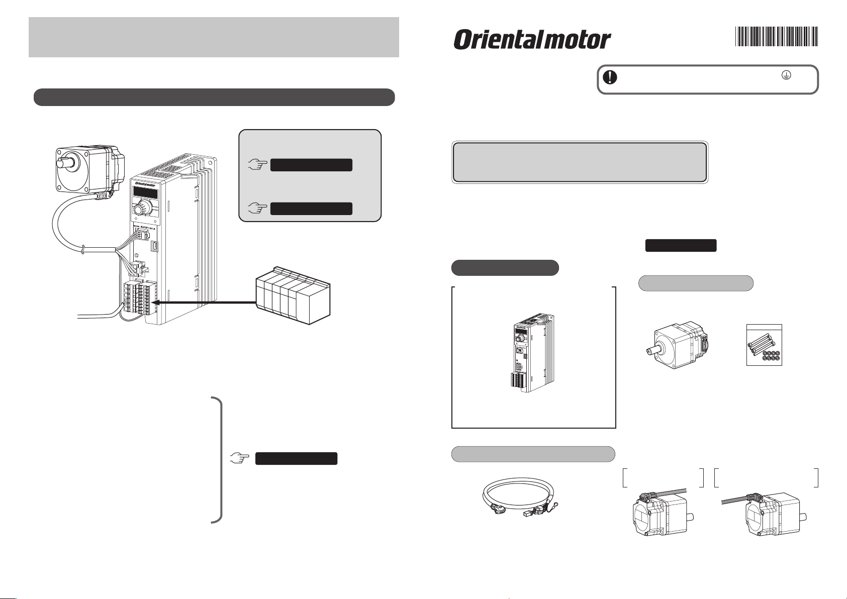
The motor can be operated by external signals
Motor
To power supply
Driver
Operating using
external signals
OPERATING MANUAL
Operating in two or
more speeds
OPERATING MANUAL
Programmable controller,
etc.
p. 33
p. 40
Be sure to ground the Protective Earth Terminal
(ground terminal) to ensure the safe use of the product.
Brushless Motors
BLE2
Series
Refer to "1 Connecting" for details, and ground securely.
QUICK START GUIDE
Thank you for purchasing an Oriental Motor product.
Use the product correctly after thoroughly reading the section "Safety precautions" of the operating
manual.
This document describes methods till rotating the motor after connecting it to the driver.
For details about how to use the product, refer to the supplied with the driver.
Package contents
The package includes the items shown below.
Driver
□
Operating manual
Motor (sold separately)
Motor
□
□
Mounting screw set
And others.....
To display the rotation speed of the
gearhead output shaft.
To display the conveyor transfer speed.
To set the rotation speed externally.
To suppress the motor torque.
To hold a load by the slight
position-keeping function.
To lock the data setting.
© Copyright
ORIENTAL MOTOR CO., LTD. 2016
As mentioned in the right, various
functions are available.
OPERATING MANUAL
Refer to "Convenient functions."
ORIENTALMOTOR CO.,LTD.
QUICK START GUIDE (this document)
□
OPERATING MANUAL
□
Connection cable (sold separately)
There are two types of connection cables
which cable leading directions are dierent.
(→ Refer to the right gure)
The gure shows an
example of the
combination type.
OPERATING MANUAL
□
Be sure to match the motor output power with the
∗
driver output power.
To connect the motor and driver, the dedicated
connection cable is always needed.
Leading in direction of
output shaft
Model:
CC__HBLF
For the round shaft type, only the cable for leading in
opposite direction of output shaft can be used.
Supplied with the
combination type.
Leading in opposite direction
of output shaft
Model:
CC__HBLB
Page 2

OPERATING MANUAL OPERATING MANUAL
1 Connecting 2 Operating a motor
Refer to "Connecting" Refer to "Operating"
Motor
Driver
CN4
Connection cable
To power supply
Ground terminal
CN2
Insert into CN1
Connect a power supply cable according to the power-supply
voltage specications of the driver. Prepare the power supply
cable since it is not supplied with the product.
Single-phase
100-120 VAC
L
N
Single-phase
200-240 VAC
L 1
L 2
Three-phase
200-240 VAC
Lead wire
Note
Screwdriver
Be sure to ground the product. Failure to do so may result in electric shock or damage to the product.
Static electricity may cause damage to the product if the Protective Earth Terminals are not grounded.
AWG18 to 14
(0.75 to 2.0 mm )
10 mm
(0.39 in.)
2
Connection for motor and cable
This is an example for when the cable is "leading
in direction of output shaft." In the case of the
cable of "leading in opposite direction of output
shaft," the cable leading direction is opposite in
3
2
and .
Remove
1
Attach
2
Locking
lever
Position of lever
Keep the locking
lever in the position
shown in the gure, and insert.
Secure
3
Be sure to turn down the locking lever
till the position shown in the gure.
Connector
cap
Ground
Be sure to ground using the
Protective Earth Terminal .
L 1
L 2
L 3
Prepare a grounding wire since
it is not supplied with the product.
AWG18 to 14 (0.75 to 2.0 mm )
Protective Earth
Terminal
M4
Grounding
Operation panel
AC power ON
1
When the power supply is turned on, the
display shows as follows.
Display: Rotation speed
0 r/min (standstill)
Operation selection
2
Press the LOCAL key.
LOCAL
3
Press
The LOCAL LED
is lit in green.
The operation using the operation
panel was set, and the rotation speed
and rotation direction are alternately
continued to show on the display.
Interval of approximately 1 second
Start of motor
4
Press
Change of motor speed
5
The motor rotates.
50 r/min (factory setting)
[ Example: 50 → 1000 r/min ]
Adjustment
Press
2
The display blinks.
You can adjust the speed while blinking.
Decelerate
MODE key
LOCAL key
LOCAL LED
Rotation direction selection
Press
The gures show the round shaft type.
∗
With the combination type, the gearhead output
shaft rotates in the opposite direction to the above
gure when the gear ratio is 30, 50, and 100.
(When the gear ratio is 30 and 50 for the 200 W type)
To stop the motor
Accelerate
Turn
The motor rotation
direction changes whenever
the MODE key is pressed.
Press
The motor stops.
Set
The display changes to lighting
from blinking, and the speed will
be set.
When you start the motor next
time, it will rotate at the set speed.
RUN key
STOP key
Setting dial
Press
 Loading...