

Page 1
Stepping Motor and Driver Package
Series/
AZ
HM-60314-2
Motorized actuator equipped with
AC power input
Pulse input type with RS-485 communication interface
Pulse input type
OPERATING MANUAL Driver
1 Introduction ................................... 2
2 Safety precautions ........................ 5
3 Precautions for use ........................ 7
4 Regulations and standards .......... 8
5 Preparation ................................... 10
6 Installation .................................... 13
7 Connection ...................................15
8 Explanation of I/O signals .......... 28
9 Setting ...........................................31
Built-in controller type
MSIP-REM-OMC-086
MSIP-REM-OMC-087
10 Guidance ....................................... 35
11 Power removal function (ETO
function: External Torque O ) .. 47
12 Inspection ..................................... 50
13 Alarm (protective function) .......51
14 Troubleshooting ..........................52
15 To use the product in more
convenient manners ................... 53
16 Accessories....................................54
AZ
Series
Thank you for purchasing an Oriental Motor product.
This Manual describes product handling procedures and safety precautions.
Please read it thoroughly to ensure safe operation.
Always keep the manual where it is readily available.
Page 2

Introduction
1 Introduction
Before use
Only quali ed personnel of electrical and mechanical engineering should work with the product.
Use the product correctly after thoroughly reading the “2 Safety precautions” on p.5. In addition, be sure to
observe the contents described in warning, caution, and note in this manual.
The product described in this manual has been designed and manufactured to be incorporated in general industrial
equipment. Do not use for any other purpose. Oriental Motor Co., Ltd. is not responsible for any damage caused
through failure to observe this warning.
This manual, unless otherwise noted, explains using gures of the built-in controller type driver.
Operating Manuals for the AZ Series
Operating manuals for the AZ Series AC power input type are listed below.
After reading these manuals, keep them in a convenient place so that you can reference them at any time.
The "AZ Series Function Edition" does not come with the product. For details, contact your nearest Oriental Motor
sales o ce or download from Oriental Motor Website download page.
Type of operating manual Description of operating manual
OPERATING MANUAL Driver
(this document)
Series Function Edition
AZ
APPENDIX UL Standards for AZ Series
(supplied with products conform to the
UL Standards)
This manual explains the functions as well as the installation/connection
method and others for the driver.
This manual explains driver functions, data setting methods, operating
methods and others which are not described in the operating manual.
This appendix includes information required for certi cation of the UL
Standards.
General speci cations
Degree of protection
Ambient temperature 0 to +55 °C (+32 to +131 °F) * (non-freezing)
Operation
environment
Storage
environment,
Shipping
environment
* When installing a driver on a heat sink. [material: aluminum, 200×200×2 mm (7.87×7.87×0.08 in.) equivalent].
Insulation resistance
Dielectric strength
Humidity 85% or less (non-condensing)
Altitude Up to 1000 m (3300 ft.) above sea level
Surrounding atmosphere No corrosive gas, dust, water or oil
Ambient temperature −25 to +70 °C (−13 to +158 °F) (non-freezing)
Humidity 85% or less (non-condensing)
Altitude Up to 3000 m (10000 ft.) above sea level
Surrounding atmosphere No corrosive gas, dust, water or oil
100 MΩ or more when 500 VDC megger is applied between the following places:
PE terminal - Main power supply terminals
Encoder connector - Main power supply terminals
Signal I/O terminals - Main power supply terminals
Su cient to withstand the following for 1 minute:
PE terminal - Main power supply terminals 1.5 kVAC 50/60 Hz
Encoder connector - Main power supply terminals 1.8 kVAC 50/60 Hz
Signal I/O terminals - Main power supply terminals 1.8 kVAC 50/60 Hz
2
IP20: Pulse input type
IP10: Built-in controller type,
Pulse input type with RS-485 communication interface
Page 3

Introduction
RS-485 communication speci cation
Electrical characteristics
Communication mode
Transmission rate
Protocol Modbus RTU mode
Number of connectable units Up to 31 units can be connected to one master controller.
* If the motor cable or power supply cable generates an undesirable amount of noise depending on the wiring or
con guration, shield the cable or install a ferrite core.
Compliant with EIA-485, straight cable
Use a twist pair cable (TIA/EIA-568B CAT5e or higher is recommended) and keep
the total wiring distance up to 50 m (164 ft.). *
Half-duplex communication
Asynchronous mode (data: 8 bits, stop bit: 1 bit/2 bits, parity: none/even
number/odd number)
Selectable from 9,600 bps, 19,200 bps, 38,400 bps, 57,600 bps, 115,200 bps, and
230,400 bps
About terms and units
Terms and units to be used vary depending on a motor or motorized actuator. This manual explains by using the
terms of the motor. When the motorized actuator is used, read this manual by replacing the terms.
Motor Motorized actuator
Torque Thrust force
Moment of inertia Mass
Rotation Movement
Ter m
Unit
CW direction Forward direction
CCW direction Reverse direction
Rotation speed Speed
Resolution Minimum travel amount
N·m N
kHz/s m/s
2
3
Page 4
Introduction
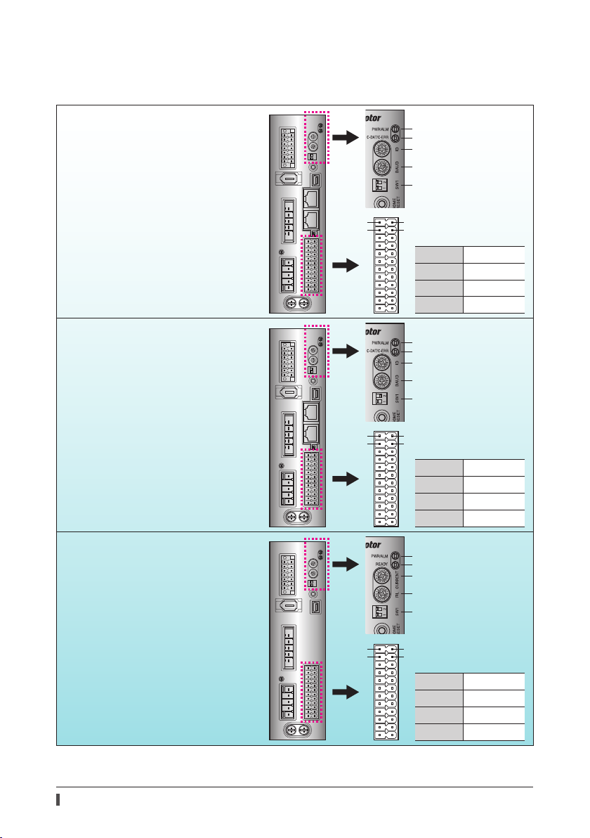
Types and overview of driver
There are 3 types of drivers in the AZ Series as shown below. I/O signals, setting items, and LEDs vary depending on
the driver type.
Built-in controller type
Operates via industrial network
Monitors the motor information via a
programmable controller or touchscreen
Operates via RS-485 communication
Operates via I/O control
Pulse input type wit RS-485
communication interface
Operates via industrial network
Monitors the motor information via a
programmable controller or touchscreen
Operates via RS-485 communication
Operates via I/O control
Operates by pulse input
PWR/ALM LED
C-DAT/C-ERR LED
Address number
Transmission rate
Function setting switch
Protocol
Address number (extended)
1
2
1
2
13
Pin Nos.1, 2, 13, and 14
14
are for control input
Pin No.1
Pin No.2
Pin No.13
Pin No.14
PWR/ALM LED
C-DAT/C-ERR LED
Address number
Transmission rate
Function setting switch
Protocol
Address number (extended)
13
14
Pin No.1
Pin No.2
Pin No.13
Pin No.14
DIN0 [START]
DIN2 [M1]
DIN1 [M0]
DIN3 [M2]
Pin Nos.1, 2, 13, and 14
are for pulse input
CW+ [PLS+]
CCW+ [DIR+]
CW- [PLS-]
CCW- [DIR-]
Pulse input type
Operates by pulse input
4
PWR/ALM LED
READY LED
Base current rate
Command lter
Function setting switch
Pulse input mode
Resolution
1
2
13
Pin Nos.1, 2, 13, and 14
14
are for pulse input
Pin No.1
Pin No.2
Pin No.13
Pin No.14
CW+ [PLS+]
CCW+ [DIR+]
CW- [PLS-]
CCW- [DIR-]
Page 5
2 Safety precautions
The precautions described below are intended to prevent danger or injury to the user and other personnel through
safe, correct use of the product. Use the product only after carefully reading and fully understanding these
instructions.
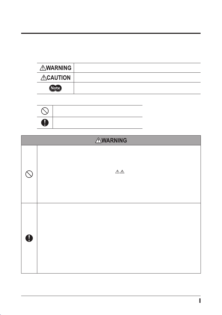
Description of signs
Handling the product without observing the instructions that accompany a "Warning"
symbol may result in serious injury or death.
Handling the product without observing the instructions that accompany a “Caution”
symbol may result in injury or property damage.
The items under this heading contain important handling instructions that the user
should observe to ensure the safe use of the product.
Description of graphic symbols
Indicates "prohibited" actions that must not be performed.
Indicates "compulsory" actions that must be performed.
Do not use the product in explosive or corrosive environments, in the presence of ammable gases, locations
subjected to splashing water, or near combustibles. This may cause re, electric shock or injur y.
Do not transport, install the product, perform connections or inspections when the power is on.
This may cause electric shock.
Do not touch the driver while the power is on. This may cause re or electric shock.
The terminals on the driver's front panel marked with
touch these terminals while the power is on. This may cause re or electric shock.
Do not forcibly bend, pull or pinch the cable. This may cause re or electric shock.
Do not turn the FREE input to ON while the motor is operating. This may cause injury or damage to equipment.
Do not touch the connection terminals on the driver immediately (within 10 minute) after the power is turned o .
This may cause electric shock.
Do not disassemble or modify the product. This may cause injury or damage to equipment.
Assign quali ed personnel the task of installing, wiring, operating/controlling, inspecting and troubleshooting the
product. Failure to do so my result in re, electric shock, injury or damage to equipment.
If this product is used in a vertical application, be sure to provide a measure for the position retention of moving
parts. Failure to do so may result in injury or damage to equipment.
When the driver generates an alarm (any of the driver's protective functions is triggered), rst remove the cause
and then clear the protective function. Continuing the operation without removing the cause of the problem may
cause malfunction of the motor and driver, leading to injury or damage to equipment.
Install the product in an enclosure. Failure to do so may result in electric shock or injury.
Keep the driver’s input-power voltage within the speci ed range. Failure to do so may result in re or electric
shock.
Since this product is Class I equipment, install it so that people cannot have contact with it, or ground it if people
may have contact with it. Failure to do so may result in electric shock.
Connect the cables securely according to the wiring diagram. Failure to do so may result in re or electric shock.
Turn o the driver power in the event of a power failure. Failure to do so may result in injury or damage to
equipment.
symbol indicate the presence of high voltage. Do not
Safety precautions
5
Page 6
Safety precautions
Do not use the product beyond its speci cations. This may cause electric shock, injury or damage to equipment.
Keep your ngers and objects out of the openings in the product. Failure to do so may result in re, electric shock
or injury.
Do not touch the product during operation or immediately after stopping. This may cause a skin burn(s).
Keep the area around the product free of combustible materials. Failure to do so may result in re or a sk in burn(s).
Leave nothing around the product that would obstruct ventilation. Failure to do so may result in damage to
equipment.
Do not forcibly bend or pull the cable that was connected to the driver. Doing so may cause damage.
Do not touch the terminals while conducting the insulation resistance test or dielectric strength test.
This may cause electric shock.
Use a motor and driver only in the speci ed combination. Failure to do so may result in re.
Take measures against static electricity when operating the switches of the driver.
Failure to do so may result in the driver malfunction or damage to equipment.
For the control power supply (24 VDC), use a DC power supply with reinforced insulation on its primary and
secondary sides. Failure to do so may result in electric shock.
Before supplying power to the driver, turn all input signals to the driver to OFF. Failure to do so may result in injury
or damage to equipment.
Provide an emergency stop device or emergency stop circuit external to the equipment so that the entire
equipment will operate safely in the event of a system failure or malfunction. Failure to do so may result in injury.
Before moving the motor directly with the hands, con rm that the FREE input turns ON. Failure to do so may result
in injury.
When an abnormal condition has occurred, immediately stop operation and turn o the driver power.
Failure to do so may result in re, electric shock or injury.
Dispose the product correctly in accordance with laws and regulations, or instructions of local governments.
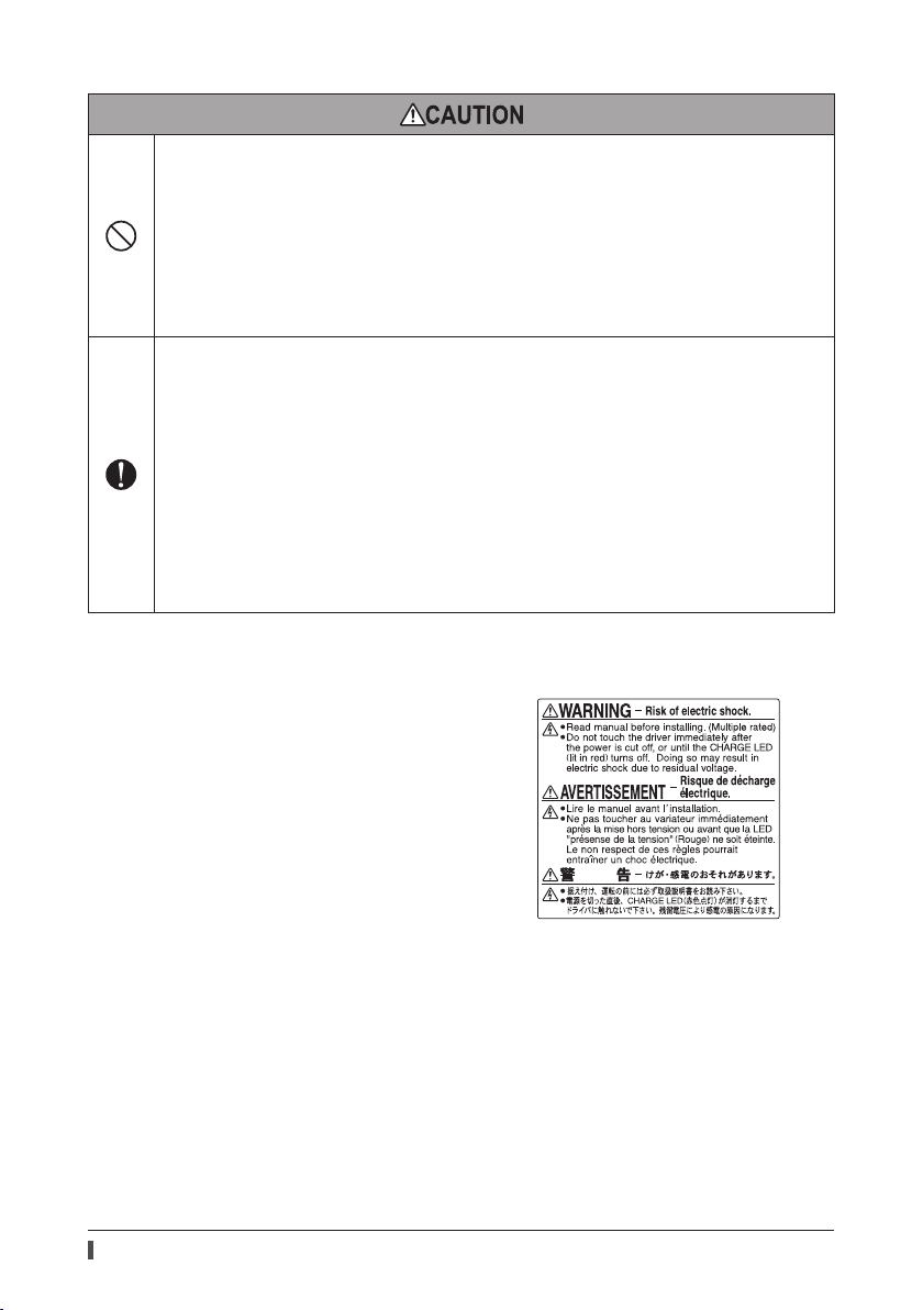
Warning sign
A warning about handling precautions is described on the
driver. Be sure to observe the description contents when
handling the driver.
Electrical hazard warning label
Material: PET
6
Page 7

3 Precautions for use
This section covers limitations and requirements the user should consider when using the product.
Always use the accessory cable to connect the motor and driver.
When conducting the insulation resistance measurement and the dielectric strength test, be sure to
separate the connection between the motor and the driver.
Conducting the insulation resistance measurement or dielectric strength test with the motor and driver connected
may result in damage to the equipment.
Preventing leakage current
Stray capacitance exists between the driver’s current-carrying line and other current-carrying lines, the earth and the
motor, respectively. A high-frequency current may leak out through such capacitance, having a detrimental e ect on
the surrounding equipment. The actual leakage current depends on the driver’s switching frequency, the length of
wiring between the driver and motor, and so on.When connecting an earth leakage breaker, use one of the following
products o ering resistance against high frequency current:
Mitsubishi Electric Corporation: NV series
Saving data to the non-volatile memory
Do not turn o the control power supply (24 VDC) while writing the data to the non-volatile memory, and also do not
turn o for 5 seconds after the completion of writing the data. Doing so may abort writing the data and cause an
EEPROM error alarm to generate. The non-volatile memory can be rewritten approximately 100,000 times.
If vertical drive (gravitational operation) such as elevator applications is performed or if sudden start-
stop operation of a large inertial load is repeated frequently, connect an accessory regeneration unit.
The overvoltage alarm may generate depending on the operating condition of the motor.
When the overvoltage alarm has generated, review the operating conditions or connect an accessory regeneration
unit. Refer to p.17 for connection method.
Note on connecting a power supply whose positive terminal is grounded
The USB communication connector, CN5, CN6 (*) and CN7 (*) connector are not insulated. When grounding the
positive terminal of the power supply, do not connect any equipment (PC, etc.) whose negative terminal is grounded.
Doing so may cause the driver and this equipment to short, damaging both. When connecting, do not ground
equipment.
* Excluding the pulse input type.
Precautions for use
7
Page 8

Regulations and standards
4 Regulations and standards
4-1 UL Standards
This product is recognized by UL under the UL Standards.
Applicable standard Certi cation body Standards File No.
UL 508C UL E171462
4-2 EU Directive
CE Marking
This product is affixed the CE Marking under the Low Voltage Directive and EMC Directive.
Low Voltage Directive
Applicable standards EN 61800-5-1
To be incorporated in equipment.
Overvoltage category: II
Installation condition
(EN Standards)
This product cannot be used in IT power distribution systems.
Install the product within the enclosure in order to avoid contact with hands.
When a product can be touched with hands, be sure to ground. Make sure to ground the Protective Earth Terminals
of the motor and driver.
To protect against electric shock using an earth leakage breaker (RCD), connect a type B earth leakage breaker to
the primary side of the driver.
When using a circuit breaker (MCCB), use a unit conforming to the EN or IEC standard.
Isolate the motor cable, power-supply cable and other drive cables from the signal cables (CN1, CN5) by means of
double insulation.
The temperature of the driver's heat sink may exceed 90 °C (194 °F) depending on the driving conditions.
Accordingly, take heed of the following items:
• Do not touch the driver.
• Do not use the driver near flammable objects.
• Always conduct a trial operation to check the driver temperature.
EMC Directive
This product is conducted EMC testing under the conditions speci ed in “Example of motor and driver installation and
wiring” on p.27. The conformance of your mechanical equipment to the EMC Directive will vary depending on such
factors as the configuration, wiring and layout for other control system devices and electrical parts used with this
product. It therefore must be verified through conducting EMC measures in a state where all parts including this
product have been installed in the equipment.
Applicable Standards
EMI EN 55011 Group1 Class A, EN 61000-6-4, EN 61800-3, EN 61000-3-2, EN 61000-3-3
EMS EN 61000-6-2, EN 61800-3
Pollution degree: 2
Degree of protection: IP20 (Pulse input type)
IP10 (Built-in controller type,
Pulse input type with RS-485 communication interface)
Protection against electric shock: Class I
This equipment is not intended for use in residential environments nor for use on a lowvoltage public network supplied in residential premises, and it may not provide
adequate protection to radio reception interference in such environments.
8
Page 9

Combinations with the motor and driver that can conform to the EMC Directive
Characters that the series name and product type can be discriminated are described in the motor model name.
Check the motor model name with the nameplate.
Driver Motor
Type Driver model Type Motor model
Built-in controller type
Pulse input type with RS-485
communication interface
Pulse input type
AZD-AD
AZD-CD
AZD-AX
AZD-CX
AZD-A
AZD-C
Standard type
Geared type
AZM46CAZM48CAZM66CAZM69CAZM98C-
AZM911C-
4-3 Republic of Korea, Radio Waves Act
This product is a xed the KC Mark under the Republic of Korea, Radio Waves Act.
4-4 RoHS Directive
The products do not contain the substances exceeding the restriction values of RoHS Directive (2011/65/EU).
Regulations and standards
9
Page 10
Preparation
5 Preparation
This chapter explains the items you should check, as well as the name and function of each part.
5-1 Checking the product
Verify that the items listed below are included. Report any missing or damaged items to the branch or sales o ce
from which you purchased the product.
Driver ........................................................ 1 unit
CN1 connector (14 pins) .................... 1 pc.
CN4 connector (5 pins) ....................... 1 pc.
CN5 connector (24 pins) .................... 1 pc.
Connector wiring lever ....................... 1 pc. (for CN4 connector)
OPERATING MANUAL Driver ............. 1 copy (this document)
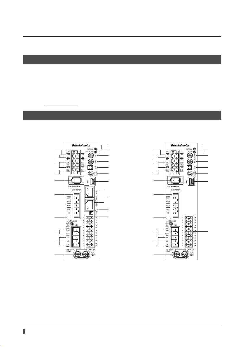
5-2 Names and functions of parts
Built-in controller type
Pulse input type with RS-485 communication interface
The gure shows the built-in controller type driver.
1
2
3
4
5
6
7
8
9
10
11
Pulse input type
12
13
14
15
16
17
18
19
20
21
1
2
3
4
5
6
7
8
9
10
11
12
13
14
15
16
17
18
21
10
Page 11
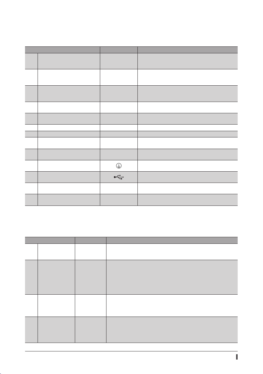
Connector, terminal
Names, indication, and functions for connectors and terminals are common to all drivers.
The RS-485 communication connectors (CN6 and CN7) are not provided in the pulse input type drivers.
Name Display Description
24 VDC power supply input
1
terminals (CN1)
Electromagnetic brake terminals
2
(CN1)
Regeneration resistor thermal input
3
terminals (CN1)
Power removal signal input
4
terminal (CN1)
Power removal monitor output
5
terminal (CN1)
6 Encoder connector (CN2) ENCODER Connects the encoder.
7 Motor connector (CN3) MOTOR Connects the motor.
Regeneration resistor terminals
9
(CN4)
Main power supply input terminals
10
(CN4)
11 Protective Earth Terminal
18 USB communication connector
RS-485 communication connector
19
(CN6/CN7)
Input/output signals connector
21
(CN5)
+24V, 0V
MB1, MB2
TH1, TH2
HWTO1+, HWTO1−
HWTO2+, HWTO2−
EDM+, EDM− Connects the programmable controller.
RG1, RG2
L, N, NC
L1, L2, L3
RS-485 Connects the RS-485 communication cable.
I/O Connects the input/output signals.
Connects the control power supply (24 VDC) of the driver.
+24V: +24 VDC power supply input
0V: Power supply ground
Connects the lead wires from the electromagnetic brake.
MB1: Electromagnetic brake− (Black)
MB2: Electromagnetic brake+ (White)
Connects the signal line of the accessory regeneration
unit. Refer to p.17 for connection method. If no regeneration
unit is connected, short the TH1 and TH2 terminals.
Connects the switch or programmable controller.
Connects the accessory regeneration unit. Refer to p.17 for
connection method.
Connects the main power supply.
Used for grounding via a grounding cable of AWG16 to 14
(1.25 to 2.0 mm
Connects the PC in which the support software
has been installed. (USB2.0 mini-B port)
2
).
Preparation
MEXE02
LED, switch
Names, indication, and functions for LEDs and switches vary depending on the driver type. Check in the table below.
Built-in controller type, Pulse input type with RS-485 communication interface
Name Display Description
8 CHARGE LED (Red) CHARGE
PWR/ALM LED
12
(Green/Red)
C-DAT/C-ERR LED
13
(Green/Red)
Address number
14
setting switch
PWR/ALM
C-DAT/C-ERR
ID
This LED is lit while the main power is input. After the main power was turned
o , the LED will turn o once the residual voltage in the driver drops to a safe
level.
This LED is lit in green while the control power supply (24 VDC) is input.
If an alarm (protective function) generates, the LED will blink in red.
If the power removal function (p.47) is triggered, the LED will blink in green.
If an information generates, the LED will blink in red and green
simultaneously. (Red and green colors may overlap and it may be visible to
orange.)
This LED will blink or illuminate in green when the driver is communicating
with the master station properly via RS-485 communication.
This LED will illuminate in red when a RS-485 communication error occurs
with the master station.
Use this switch when controlling the system via RS-485 communication.
Use this switch and SW1-No.1 of the function setting switch, to set the
address number of RS-485 communication.
Factory setting Built-in controller type: 0
Pulse input type with RS-485 communication interface: 1
11
Page 12

Preparation
Name Display Description
Transmission rate
15
setting switch
Function setting
16
switch
HOME PRESET
17
switch
Termination resistor
20
setting switch
HOME PRESET
Pulse input type
Name Display Description
8 CHARGE LED (Red) CHARGE
PWR/ALM LED
12
(Green/Red)
13 READY LED (Green) READY
Current setting
14
switch
Command lter
15
setting switch
Function setting
16
switch
HOME PRESET
17
switch
PWR/ALM
CURRENT
HOME PRESET
BAUD
SW1
TERM.
FIL
SW1
Use this switch when controlling the system via RS-485 communication.
Set the transmission rate of RS-485 communication.
Factory setting Built-in controller type: 7
Pulse input type with RS-485 communication interface: 4
Use this switch when controlling the system via RS-485 communication.
No.1: Using this switch and the address number setting switch (ID), set the
address number of RS-485 communication.
Factory setting: OFF
No.2: Set the protocol of RS-485 communication.
Factory setting Built-in controller type: OFF
Pulse input type with RS-485 communication interface: ON
This switch is used to set the starting position (home position) when
performing positioning operation.
Use this switch when controlling the system via RS-485 communication. Set
the termination resistor (120 Ω) of RS-485 communication.
Factory setting Both No.1 and No.2 are OFF
This LED is lit while the main power is input. After the main power was turned
o , the LED will turn o once the residual voltage in the driver drops to a safe
level.
This LED is lit in green while the control power supply (24 VDC) is input.
If an alarm (protective function) generates, the LED will blink in red.
If the power removal function (p.47) is triggered, the LED will blink in green.
If an information generates, the LED will blink in red and green
simultaneously. (Red and green colors may overlap and it may be visible to
orange.)
This LED is lit while the READY output is ON. It is not lit when the READY
output is OFF.
This switch is used to set the base current rate for the operating current and
standstill current.
Factory setting: F
This switch adjusts the motor response.
Factory setting: 1
No.1: This switch is used to set the resolution per revolution of the motor
output shaft.
Factory setting: OFF (1000 p/r)
No.2: This switch is used to toggle between the 1-pulse input mode and
2-pulse input mode.
The factory setting of the pulse-input mode depends on the destination
country.
This switch is used to set the starting position (home position) when
performing positioning operation.
12
Page 13
6 Installation
This chapter explains the installation location and installation method of the driver.
6-1 Location for installation
The driver has been designed and manufactured to be incorporated in equipment. Install it in a well-ventilated
location that provides easy access for inspection.
The location must also satisfy the following conditions:
Inside an enclosure that is installed indoors (provide vent holes)
Operating ambient temperature 0 to +55 °C (+32 to +131 °F) (non-freezing)
Operating ambient humidity 85% or less (non-condensing)
Area that is free of explosive atmosphere or toxic gas (such as sulfuric gas) or liquid
Area not exposed to direct sun
Area free of excessive amount of dust, iron particles or the like
Area not subject to splashing water (rain, water droplets), oil (oil droplets) or other liquids
Area free of excessive salt
Area not subject to continuous vibration or excessive shocks
Area free of excessive electromagnetic noise (from welders, power machinery, etc.)
Area free of radioactive materials, magnetic elds or vacuum
1000 m (3300 ft.) or lower above sea level
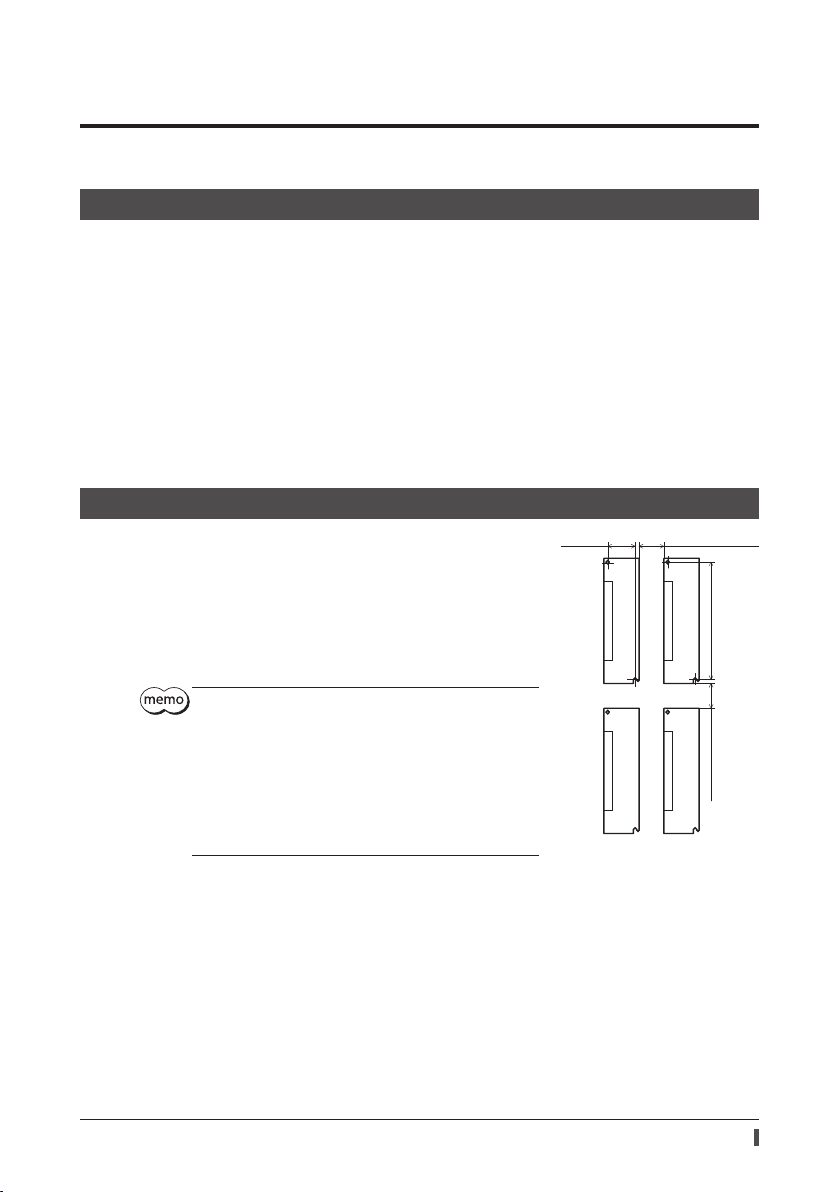
6-2 Installation method
The driver is designed so that heat is dissipated via air convection and
conduction through the enclosure. Install the driver on a at metal plate (*)
having excellent heat conductivity.
There must be a clearance of at least 25 mm (0.98 in.) in the horizontal and
vertical directions, between the driver and enclosure or other equipment
within the enclosure.
When installing the driver in an enclosure, use two screws (M4, not
supplied) to secure the driver through the mounting holes.
* Material: aluminum, 200×200×2 mm equivalent (7.87×7.87×0.08 in.)
Install the driver in an enclosure whose pollution degree is 2
or better environment, or whose degree of protection is IP54
minimum.
Do not install any equipment that generates a large amount
of heat or noise near the driver.
Do not install the driver underneath the controller or other
equipment vulnerable to heat.
If the ambient temperature of the driver exceeds 55 °C
(131 °F), improve the ventilation condition.
Be sure to install the driver vertically (vertical position).
35 (1.38)
Installation
25 (0.98) or more
150 (5.91)
25 (0.98) or more
Unit: mm (in.)
13
Page 14
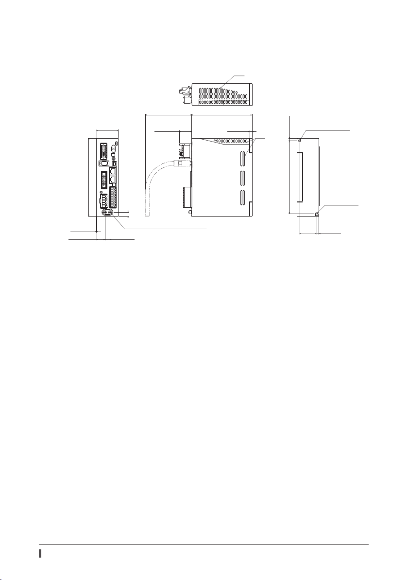
Installation
Dimension [unit: mm (in.)]
The dimension is common to all drivers.
Mass: 0.65 kg (1.43 lb)
45 (1.77)
[
95 (3.74
25 (0.98)
Slit
)]
125 (4.92)
5 (0.20)
Slit
Ø4.5 (0.177) hole
5 (0.20)
160 (6.30)
0.5 (0.02)
17.5 (0.69) 10 (0.39)
Protective Earth Terminal 2×M4
8.1 (0.32)
150 (5.91)
35
(1.38)
R2.25 (0.089)
5 (0.20)
14
Page 15
7 Connection
This chapter explains how to connect the motor, power supply and I/O signals to the driver, as well as grounding
method.
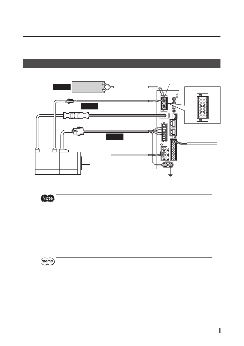
7-1 Connection example
The following gure shows models for the electromagnetic brake type and single-phase 200 to 240 VAC input.
Required
Control power
supply (24 VDC)
Required
Connect to +24 V and 0V
Connect to MB1 and MB2
Cable for electromagnetic brake
Connect to ENCODER
Cable for encoder
Connect to MOTOR
Required
Cable for motor
Connect to L1 and L2
Main power supply
Single-phase 200-240 V
CN1 connector
Grounding
Connection
CN1 connector
+24 V
MB1
Connect to CN5
I/O signals
0 V
MB2
* Cables represented in gray color are accessories. Use the cable for encoder when the length of the encoder cable of
motor is not enough.
Have the connector plugged in securely. Insecure connections may cause malfunction or damage
to the motor or driver.
When plugging/unplugging the connector, turn o the power and wait for the CHARGE LED to
turn o before doing so. The residual voltage may cause electric shock.
Do not wire the power supply cable of the driver in the same cable duct with other power lines or
motor cables. Doing so may cause malfunction due to noise.
The lead wires of the "cable for electromagnetic brake" have polarities, so connect them in the
correct polarities. If the lead wires are connected with their polarities reversed, the electromagnetic
brake will not operate properly.
Keep 20 m (65.6 ft.) or less for the wiring distance between the motor and driver. To extend more
than 20 m (65.6 ft.) may result in the driver heat generation or increase of the electrical noise
emitted from the product.
The control power supply (24 VDC) is required with or without an electromagnetic brake. Be sure
to connect it.
When unplugging the motor cable, do so while pressing the latches on the connector.
When installing the motor on a moving part, use an accessory exible cable having excellent ex
resistance.
15
Page 16

Connection
7-2 Connecting to CN1
Wiring the CN1 connector
Applicable lead wire: AWG24 to 16 (0.2 to 1.25 mm2)
Length of the insulation cover which can be peeled: 10 mm (0.39 in.)
1. Strip the insulation cover of the lead wire.
2. Insert the lead wire while pushing the button of the orange color with
a slotted screwdriver.
3. After having inserted, release the button to secure the lead wire.
Pin assignment list
Button of the
orange color
Lead wire
+24V
MB1
TH1
+V
HWTO1
-
HWTO2
-
EDM+
Display Description
Connects the control power supply (24 VDC).
+24V, 0V
MB1, MB2
TH1, TH2
HWTO1+, HWTO1−
HWTO2+, HWTO2−
EDM+, EDM− Connects the programmable controller.
+V, 0V
When the electromagnetic brake is not used: 24 VDC±5% 0.25 A
When the electromagnetic brake is used: 24 VDC±5% 0.5 A (0.33 A for
When the electromagnetic brake is used and the distance between the motor and
driver is 20 m (65.6 ft.): 24 VDC±4% 0.5 A (0.33 A for
Connects the lead wires from the electromagnetic brake.
MB1: Electromagnetic brake− (Black)
MB2: Electromagnetic brake+ (White)
Connects the signal line of the accessory regeneration unit. If the regeneration unit is not
used, connect a jumper wire between the terminals as shown in the gure.
Connects the switch or programmable controller. If the power removal function is not
used, connect a jumper wire between the terminals as shown in the gure.
For internal connections. Do not connect anything. If the power removal function is not
used, connect a jumper wire between the terminals as shown in the gure.
0V
MB2
TH2
HWTO1+
HWTO2+
0V
EDM
-
)
AZM46
)
AZM46
16
Page 17
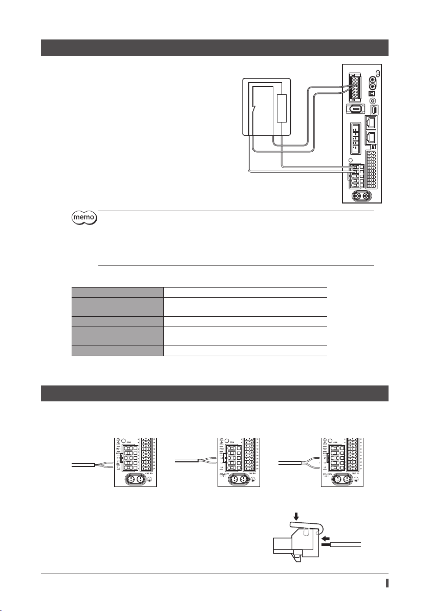
7-3 Connecting the regeneration unit
V
Connection
Connect the accessory regeneration unit if gravitational
operation or other operations involving up/down
movement, or sudden starting/stopping of a large inertial
load, will be repeated frequently.
The two thin lead wires (AWG22: 0.3 mm
regeneration unit are the thermostat outputs. Connect
them to the TH1 and TH2 using the CN1 connector.
Regenerative current flows through the two thick lead
wires (AWG18: 0.75 mm
Connect them to the RG1 and RG2 using the CN4
connector.
Before connecting the regeneration unit, be sure to remove the jumper wire from the CN1
connector.
If the allowable power consumption of the regeneration unit exceeds the allowable level, the
thermostat will be triggered and the regeneration unit overheat alarm of the driver will generate. If
the regeneration unit overheat alarm generates, turn o the power and check the connection or
operating condition.
2
) of the regeneration unit.
2
) of the
Regeneration unit
150 °C (302 °F)
R: 150 Ω
[N.C.]
CN1
To TH1 and TH2
AWG22
To RG1 and RG2
CN4
AWG18
Regeneration unit speci cation
Model
Allowable current consumption
Resistance value 150 Ω
Thermostat operating
temperature
Thermostat electrical rating 120 VAC 4 A, 30 VDC 4 A (minimum current: 5 mA)
* Install the regeneration unit in a location where heat dissipation capacity equivalent to a level achieved with a heat
sink [made of aluminum, 350×350×3 mm (13.78×13.78×0.12 in.)] is ensured.
RGB100
Continuous regenerative power: 50 W *
Instantaneous regenerative power: 600 W
Operation: Opens at 150±7 °C (302±12.6 °F)
Reset: Closes at 145±12 °C (293±21.6 °F) [normally closed]
7-4 Connecting the power supply
The connecting method varies depending on the power supply speci cation.
Single-phase 100-120 V
-
Connect to
L and N
Wiring the CN4 connector
Applicable lead wire: AWG18 to 14 (0.75 to 2.0 mm2)
Length of the insulation cover which can be peeled: 9 mm (0.35 in.)
1. Insert the connector lever.
2. Insert the lead wire while pushing down the connector lever.
15 to +6% 50/60 Hz
Connect to
L1 and L2
Single-phase 200-240 V
-
15 to +6% 50/60 Hz
Connect to
L1, L2 and L3
Three-phase 200-240
-
15 to +6% 50/60 Hz
Lead wire
17
Page 18
Connection
Power supply current capacity
The current capacity for the power supply varies depending on the motor combined.
When motorized actuators are used, check while referring to the model name of the equipped motor.
Single-phase 100-120 V Single-phase 200-240 V Three-phase 200-240 V
Model
AZM46
AZM48
AZM66
AZM69
AZM98
AZM911
Power supply
current capacity
2.7 A or more
2.7 A or more
3.8 A or more
5.4 A or more
5.5 A or more
6.4 A or more
Model
AZM46
AZM48
AZM66
AZM69
AZM98
AZM911
Power supply
current capacity
1.7 A or more
1.6 A or more
2.3 A or more
3.3 A or more
3.3 A or more
3.9 A or more
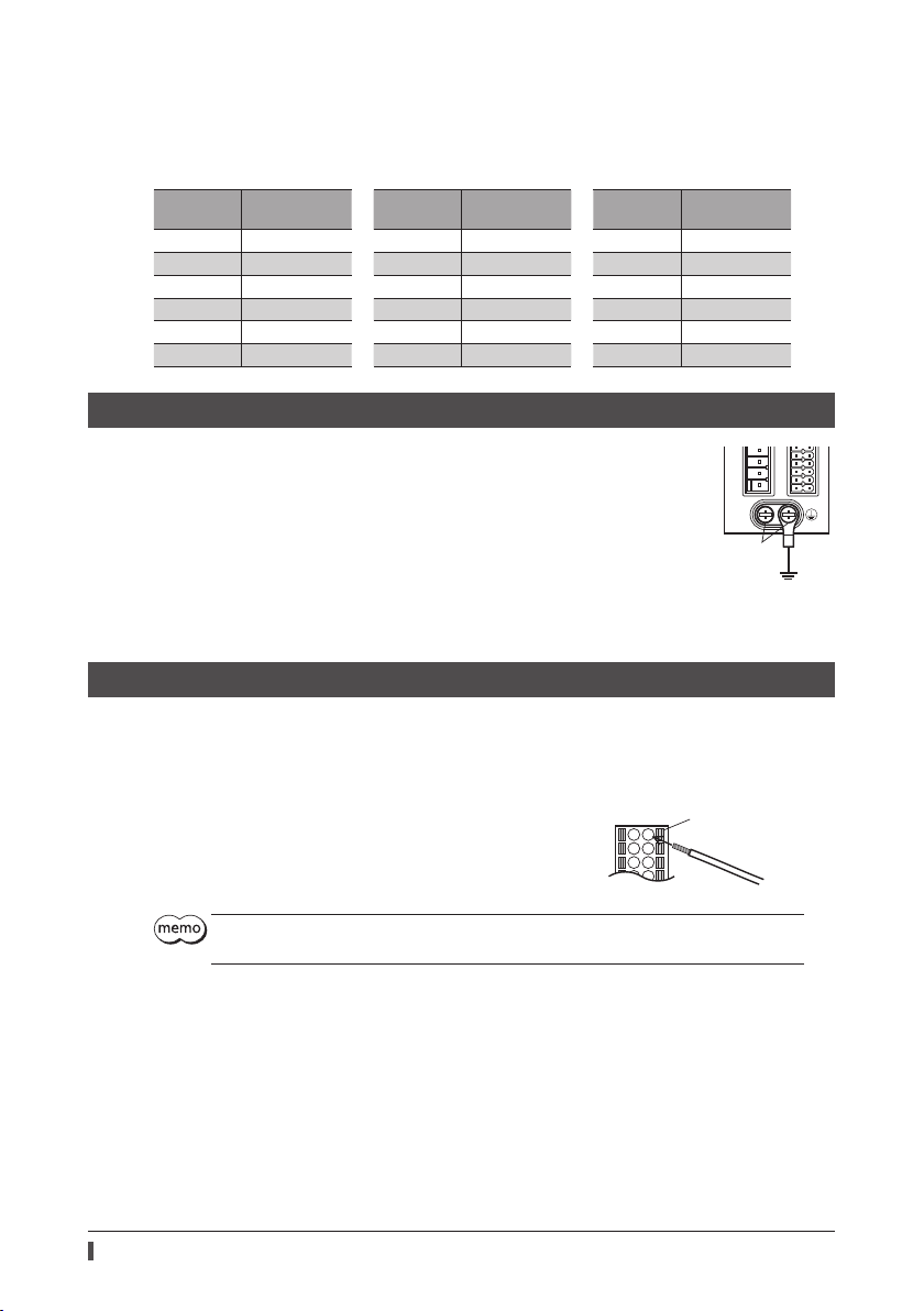
7-5 Grounding
Two Protective Earth Terminals (screw size: M4) are provided on the
driver. Be sure to ground one of the Protective Earth Terminals. You can
ground either of the two Protective Earth Terminals.
Grounding wire: AWG16 to 14 (1.25 to 2.0 mm
Tightening torque: 1.2 N·m (170 oz-in)
Connect the grounding wire of the "cable for motor" to the other
terminal to ground the motor.
Do not share the grounding wire with a welder or any other power
equipment.
When grounding the Protective Earth Terminal, use a round terminal
and secure the grounding point near the driver.
2
)
(Ground one of these terminals.)
7-6 Connecting the I/O signals
Model
AZM46
AZM48
AZM66
AZM69
AZM98
AZM911
Protective Earth Terminal
Power supply
current capacity
1.0 A or more
1.0 A or more
1.4 A or more
2.0 A or more
2.0 A or more
2.3 A or more
Grounding
Wiring the CN5 connector
Applicable lead wire: AWG24 to 16 (0.2 to 1.25 mm2)
Length of the insulation cover which can be peeled: 10 mm (0.39 in.)
1. Strip the insulation cover of the lead wire.
2. Insert the lead wire while pushing the button of the orange color with
a slotted screwdriver.
3. After having inserted, release the button to secure the lead wire.
Be certain the I/O signal cable is as short as possible. The maximum input frequency will decrease as
the cable length increases.
18
Button of the
orange color
Lead wire
Page 19

Connection
Pin assignment list
Built-in controller type
Pin
Signal name Description *
No.
1 IN0 Control input 0 (START) 13 IN1 Control input 1 (M0)
2 IN2 Control input 2 (M1) 14 IN3 Control input 3 (M2)
3 IN4 Control input 4 (ZHOME) 15 IN5 Control input 5 (FREE)
4 IN6 Control input 6 (STOP) 16 IN7 Control input 7 (ALM-RST)
5 IN-COM [0-7] IN0 to IN7 input common 17 IN-COM [8-9] IN8, IN9 input common
6 IN8 Control input 8 (FW-JOG) 18 IN9 Control input 9 (RV-JOG)
7 OUT0
8 OUT2 Control output 2 (PLS-RDY) 20 OUT3 Control output 3 (READY)
9 OUT4 Control output 4 (MOVE) 21 OUT5 Control output 5 (ALM-B)
10 OUT-COM Output common 22 GND Ground
11 ASG+ A-phase pulse output+ 23 ASG− A-phase pulse output−
12 BSG+ B-phase pulse output+ 24 BSG− B-phase pulse output−
Control output 0
(HOME-END)
* ( ): Initial value * ( ): Initial value
1 13
12 24
Pulse input type with RS-485 communication interface, pulse input type
Pin
Signal name Description *
No.
1 CW+ [PLS+]
CCW+
2
[DIR+]
3 IN4 Control input 4 (ZHOME) 15 IN5 Control input 5 (FREE)
4 IN6 Control input 6 (STOP) 16 IN7
5 IN-COM [4-7] IN4 to IN7 input common 17 IN-COM [8-9] IN8, IN9 input common
6 IN8 Control input 8 (FW-JOG) 18 IN9 Control input 9 (RV-JOG)
7 OUT0
8 OUT2 Control output 2 (PLS-RDY) 20 OUT3
9 OUT4 Control output 4 (MOVE) 21 OUT5
10 OUT-COM Output common 22 GND Ground
11 ASG+ A-phase pulse output+ 23 ASG− A-phase pulse output−
12 BSG+ B-phase pulse output+ 24 BSG− B-phase pulse output−
CW pulse input+
[Pulse input+]
CCW pulse input+
[Direction input +]
Control output 0
(HOME-END)
* ( ): Initial value * ( ): Initial value
1 13
12 24
Pin
Signal name Description *
No.
19 OUT1 Control output 1 (IN-POS)
Pin
Signal name Description *
No.
13 CW− [PLS−]
CCW−
14
[DIR−]
19 OUT1
CW pulse input−
[Pulse input−]
CCW pulse input−
[Direction input−]
Control input 7
(ALM-RST)
Control output 1
(IN-POS)
Control output 3
(READY)
Control output 5
(ALM-B)
19
Page 20

Connection
7-7 Connection diagram
Connecting to a current sink output circuit
The gure below shows a connection example of the built-in controller type driver. In the case of the pulse input type
with RS-485 communication interface and the pulse input type, the pin No.1, No.2, No.13, and No.14 are only available
to the pulse input. Refer to p.21 for connection example.
DriverController
IN0 (START)
IN4 (ZHOME)
IN5 (FREE)
IN6 (STOP)
IN7 (ALM-RST)
24 VDC
0 V
24 VDC
0 V
12 to 24 VDC
R0
10 mA or less
IN-COM [0-7]
IN8 (FW-JOG)
IN9 (RV-JOG)
IN-COM [8-9]
OUT0 (HOME-END)
IN1 (M0)
IN2 (M1)
IN3 (M2)
1
4.7 kΩ
13
4.7 kΩ
2
4.7 kΩ
14
4.7 kΩ
3
4.7 kΩ
15
4.7 kΩ
4
4.7 kΩ
16
4.7 kΩ
5
6
4.7 kΩ
18
4.7 kΩ
17
7
2.2 kΩ
2.2 kΩ
2.2 kΩ
2.2 kΩ
2.2 kΩ
2.2 kΩ
2.2 kΩ
2.2 kΩ
2.2 kΩ
2.2 kΩ
R0
R0
R0
R0
R0
0 V
0 V
Twisted pair cable
OUT1 (IN-POS)
OUT2 (PLS-RDY)
OUT3 (READY)
OUT4 (MOVE)
OUT5 (ALM-B)
OUT-COM
ASG+
ASG
BSG+
BSG
GND
19
8
Output saturated
20
9
21
10
11
23
12
24
22
voltage 3 V max.
26C31 or equivalent
0 V
* ( ): Initial value
20
Page 21

Use input signals at 24 VDC.
Use output signals at 12 to 24 VDC, 10 mA or less. If the current exceeds 10 mA, connect an
external resistor R0 so that the current becomes 10 mA or less.
The saturated voltage of the output signal is 3 VDC maximum.
Pulse input type with RS-485 communication interface, pulse input type
The pin No.1, No.2, No.13, and No.14 are only available to the pulse input. Other functions cannot be assigned.
When pulse input is of line driver type
DriverController
270 Ω
Twisted pair cable
0 V
CW+ [PLS+]
-
[PLS-]
CW
CCW+ [DIR+]
-
[DIR-]
CCW
470 Ω
1
13
2
14
470 Ω
270 Ω
270 Ω
270 Ω
When pulse input is of open-collector type (When using the voltage of pulse input signals at 5 VDC)
5 VDC
0 V
Twisted pair cable
CW+ [PLS+]
-
[PLS-]
CW
CCW+ [DIR+]
-
[DIR-]
CCW
470 Ω
1
13
470 Ω
2
14
DriverController
270 Ω
270 Ω
270 Ω
270 Ω
Connection
5.6 kΩ
5.6 kΩ
5.6 kΩ
5.6 kΩ
When pulse input is of open-collector type (When using the voltage of pulse input signals at 24 VDC)
24 VDC
0 V
Twisted pair cable
R1
1.2 kΩ to 2.2 k
0.5 W or more
R1
1.2 kΩ to 2.2 k
0.5 W or more
Use the CW [PLS] input and CCW [DIR] input at 5 VDC to 24 VDC. When using signals at 24 VDC,
connect an external resistor R1 (1.2 kΩ to 2.2 kΩ, 0.5 W or more). When using signals at 5 VDC, apply
the voltage directly.
CW+ [PLS+]
-
[PLS-]
CW
CCW+ [DIR+]
-
[DIR-]
CCW
470 Ω
1
13
470 Ω
2
14
DriverController
270 Ω
270 Ω
270 Ω
270 Ω
5.6 kΩ
5.6 kΩ
21
Page 22

Connection
Connecting to a current source output circuit
The gure below shows a connection example of the built-in controller type driver. In the case of the pulse input type
with RS-485 communication interface and the pulse input type, the pin No.1, No.2, No.13, and No.14 are only available
to the pulse input. Refer to p.23 for connection example.
24 VDC
IN0 (START)
IN4 (ZHOME)
IN5(FREE)
IN6 (STOP)
IN7 (ALM-RST)
IN-COM [0-7]
0 V
24 VDC
IN8 (FW-JOG)
IN9 (RV-JOG)
IN-COM [8-9]
0 V
12 to 24 VDC
R0
10 mA or less
OUT0 (HOME-END)
IN1 (M0)
IN2 (M1)
IN3 (M2)
1
4.7 kΩ
13
4.7 kΩ
2
4.7 kΩ
14
4.7 kΩ
3
4.7 kΩ
15
4.7 kΩ
4
4.7 kΩ
16
4.7 kΩ
5
6
4.7 kΩ
18
4.7 kΩ
17
7
DriverController
2.2 kΩ
2.2 kΩ
2.2 kΩ
2.2 kΩ
2.2 kΩ
2.2 kΩ
2.2 kΩ
2.2 kΩ
2.2 kΩ
2.2 kΩ
R0
R0
R0
R0
R0
0 V
Twisted pair cable
0 V
OUT1 (IN-POS)
OUT2(PLS-RDY)
OUT3 (READY)
OUT4 (MOVE)
OUT5 (ALM-B)
OUT-COM
ASG+
ASG
BSG+
BSG
GND
19
8
Output saturated
20
9
21
10
11
23
12
24
22
voltage 3 V max.
26C31 or equivalent
0 V
* ( ): Initial value
22
Page 23

Use input signals at 24 VDC.
Use output signals at 12 to 24 VDC, 10 mA or less. If the current exceeds 10 mA, connect an
external resistor R0 so that the current becomes 10 mA or less.
The saturated voltage of the output signal is 3 VDC maximum.
Pulse input type with RS-485 communication interface, pulse input type
The pin No.1, No.2, No.13, and No.14 are only available to the pulse input. Other functions cannot be assigned.
When pulse input is of line driver type
DriverController
270 Ω
Twisted pair cable
0 V
CW+ [PLS+]
-
[PLS-]
CW
CCW+ [DIR+]
-
[DIR-]
CCW
470 Ω
1
13
2
14
470 Ω
270 Ω
270 Ω
270 Ω
When pulse input is of open-collector type (When using the voltage of pulse input signals at 5 VDC)
Controller
5 VDC
CW+ [PLS+]
-
[PLS-]
0 V
Twisted pair cable
CW
CCW+ [DIR+]
-
[DIR-]
CCW
470 Ω
1
13
470 Ω
2
14
Driver
270 Ω
270 Ω
270 Ω
270 Ω
Connection
5.6 kΩ
5.6 kΩ
5.6 kΩ
5.6 kΩ
When pulse input is of open-collector type (When using the voltage of pulse input signals at 24 VDC)
Controller
24 VDC
1.2 kΩ to 2.2 k
0.5 W or more
R1
1.2 kΩ to 2.2 k
0.5 W or more
R1
0 V
Use the CW [PLS] input and CCW [DIR] input at 5 VDC to 24 VDC. When using signals at 24 VDC,
connect an external resistor R1 (1.2 kΩ to 2.2 kΩ, 0.5 W or more). When using signals at 5 VDC, apply
the voltage directly.
Twisted pair cable
CW+ [PLS+]
-
[PLS-]
CW
CCW+ [DIR+]
-
[DIR-]
CCW
470 Ω
1
13
470 Ω
2
14
Driver
270 Ω
270 Ω
270 Ω
270 Ω
5.6 kΩ
5.6 kΩ
23
Page 24

Connection
7-8 Connecting the RS-485 communication cable
Connect this cable if you want to control your product via
RS-485 communication. Connect the RS-485 communication
cable to CN6 or CN7 on the driver. You can use the vacant
connectors to connect a di erent driver.
A driver link cable is available as an accessory. A commerciallyavailable LAN cable (straight cable) can also be used to link
drivers.
Pin assignment list
Pin No. Signal name Description
1 N.C. Not used
2 GND GND
3 TR+ RS-485 communication signal (+)
4 N.C.
5 N.C.
6 TR− RS-485 communication signal (−)
7 N.C.
8 N.C.
Internal input circuit
Not used
Not used
RS-485
communication cable
Drivers can
be linked.
1
•
•
•
8
2 GND
3 TR+
6 TR
-
2 GND
3 TR+
6 TR
-
0 V
TERM.
No.1
5 V
1 kΩ
120 Ω
TERM.
No.2
1 kΩ
0 V
7-9 Connecting the USB cable
Using a USB cable of the following speci cation, connect a PC in which the
communication connector.
Speci cation USB2.0 (Full Speed)
Cable
24
Length: 3 m (9.8 ft.) or less
Type: A to mini B
Connect the driver and PC directly using the USB cable.
In large electrically noisy environments, use the USB cable with a ferrite core or install a ferrite core
to the USB cable.
has been installed to the USB
MEXE02
Page 25

7-10 Noise measures
The electrical noise is of two types: One is a noise to invade into the driver from the outside and cause the driver
malfunction, and the other is a noise to emit from the driver and cause peripheral equipments malfunction.
For the noise that is invaded from the outside, take measures to prevent the driver malfunction. It is needed to take
adequate measures because signal lines are very likely to be a ected by the noise.
For the noise that is emitted from the driver, take measures to suppress it.
Measures against electrical noise
There are the following three methods mainly to take measures against the electrical noise.
Noise suppression
When relays or electromagnetic switches are used together with the system, use noise lters and CR circuits to
suppress surges generated by them.
Use an accessory cable when extending a wiring distance between the motor and driver. This is e ective in
suppressing the electrical noise emitted from the motor.
Cover the driver by a metal plate such as aluminum. This is e ective in shielding the electrical noise emitted from
the driver.
Prevention of noise propagation
Connect a noise lter in the power supply cable of driver.
Place the power lines, such as the motor and power supply cables, keeping a distance of 200 mm (7.87 in.) or more
from the signal lines, and also do not bundle them or wire them in parallel. If the power cables and signal cables
have to cross, cross them at a right angle.
Use shielded twisted pair cables for power lines and signal lines.
Keep cables as short as possible without coiling and bundling extra lengths.
When grounding PE terminals of multiple drivers to a grounding point, it becomes more e ective to block the
electrical noise since impedance on the grounding point is decreased. However, ground them so that a potential
di erence does not occur among the grounding points. An accessory driver cable including with a ground wire is
available.
To ground a shielded cable, use a metal cable clamp that will maintain
contact with the entire circumference of the cable. Ground the cable
clamp near the product.
Suppression of e ect by noise propagation
Loop the noise propagated cable around a ferrite core. Doing so will prevent the propagated noise invades into
the driver or emits from the driver. The frequency band in which an e ec t by the ferrite core can be seen is
generally 1 MHz or more. Check the frequency characteristics of the ferrite core used. To increase the e ect of noise
attenuation by the ferrite core, loop the cable a lot.
Use the line driver type, which is less likely to be a ected by electrical noise, for the output circuit of pulse signals.
When the pulse signal of the controller is the open collector type, use an accessory pulse signal converter for noise
immunity.
Shielded cable
Connection
Cable clamp
Noise suppression parts
Noise lter
Connect the following noise lter (or equivalent) to the power line. Doing so will prevent the propagated noise
through the power line. Install the noise lter as close to the driver as possible.
Manufacture
SOSHIN ELECTRIC CO.,LTD HF2010A-UPF HF3010C-SZA
Scha ner EMC FN2070-10-06 FN3025HP-10-71
Use the AWG18 (0.75 mm
using a cable clamp etc. so that the cable does not come o the enclosure.
Place the input cable as far apart as possible from the output cable, and do not wire the cables in parallel. If the
input and output cable are placed at a close distance or if they are wired in parallel, the noise in the enclosure
a ects the power cable through stray capacitance, and the noise suppressing e ect will reduce.
Connect the ground terminal of the noise lter to the grounding point, using as thick and short a wire as possible.
When connecting a noise lter in an enclosure, wire the input cable of the noise lter as short as possible. Wiring in
long distance may reduce the noise suppressing e ect.
Single-phase 100-120 V
Single-phase 200-240 V
2
) or thicker wire for the input and output cables of the noise lter, and secure rmly
Three-phase 200-240 V
25
Page 26

Connection
Noise suppression parts (accessories)
Refer to p.54 for accessories.
Driver cable
This cable is a shielded cable for good noise immunity to connect the driver and controller. The ground wires useful to
grounding are provided at both ends of the cable. The EMC measures are conducted using the Oriental Motor driver
cable.
Pulse signal converter for noise immunity
This is a noise lter for pulse signal lines. It eliminates the noise of the pulse signal and changes the pulse signal to the
line driver type.
Surge suppressor
This product is e ective to suppress the surge which occurs in a relay contact part. Connect it when using a relay or
electromagnetic switch. CR circuit for surge suppression and CR circuit module are provided.
7-11 Installing and wiring in compliance with EMC Directive
E ective measures must be taken against the EMI that the motor and driver may give to adjacent control-system
equipment, as well as the EMS of the motor and driver itself, in order to prevent a serious functional impediment in
the machinery. The use of the following installation and wiring methods will enable the motor and driver to be
compliant with the EMC directive. Refer to p.8 for the applicable standards.
Oriental Motor conducts EMC measurements on its motors and drivers in accordance with “Example of motor and
driver installation and wiring” on p.27.
The user is responsible for ensuring the machine's compliance with the EMC Directive, based on the installation and
wiring explained below.
Connecting the noise lter
In large electrically noisy environments, connect a noise lter. Refer to “Noise lter ” on p.25 for details.
Connecting the AC power line reactor
When inputting single-phase 240 V, insert a reactor (5 A, 5 mH) in the AC power line to ensure compliance with EN
61000-3-2.
Connecting the control power supply (24 VDC)
Use a control power supply (24 VDC) compliant with the EMC Directive.
Use a shielded cable for the wiring , and keep it as short as possible.
Refer to “Prevention of noise propagation” on p.25 for grounding the shielded cable.
Connecting the motor cable
Use an accessory extension cable when extending the wiring distance between the motor and driver.
Connecting the signal cable
Refer to “Prevention of noise propagation” on p.25.
How to ground
The cable used to ground the motor, driver and noise lter must be as thick and shor t as possible so that no
potential di erence is generated.
Choose a large, thick and uniformly conductive surface for the grounding point.
Be sure to ground the Protective Earth Terminal of the motor and driver. Refer to p.18 for grounding method.
26
Page 27

Example of motor and driver installation and wiring
The driver uses parts that are sensitive to electrostatic charge. Take measures against static electricity
since static electricity may cause the driver to malfunction or su er damage.
Built-in controller type, pulse input type with RS-485 communication interface
Control power
AC
Grounding
Noise
lter
supply (24 VDC)
Grounding
Motor
AC
Shielded cable
Cable for
electromagnetic brake
Cable for encoder
Cable for motor
Cable
clamp
Cable
clamp
Grounding
Noise
lter
GroundingGrounding
- - - is a shielded box. Cables represented in gray color are accessories.
Driver
Grounding
RS-485
communication cable
Pulse input type
Control power
AC
Grounding
Noise
lter
supply (24 VDC)
Grounding
Shielded cable
Cable for
electromagnetic brake
Cable for encoder
Cable
clamp
Grounding
Driver
Signal cable
(Driver cable)
Grounding
Grounded panel
Grounding
Grounding
Connection
Master
controller
Grounding
Motor
AC
Cable for motor
Cable
clamp
Signal cable
Noise
lter
GroundingGrounding
Grounding
- - - is a shielded box. Cables represented in gray color are accessories.
(Driver cable)
Grounding
Grounded panel
Controller
Grounding
Grounding
Grounding
27
Page 28

Explanation of I/O signals
8 Explanation of I/O signals
8-1 Input signals
The following input signals of the driver are photocoupler inputs. The signal state represents the "ON: Carrying
current" or "OFF: Not carrying current" state of the internal photocoupler rather than the voltage level of the signal.
CW [PLS] input, CCW [DIR] input
These signals are used when the motor is operated by inputting pulses.
These inputs serve as the CW and CCW inputs in the 2-pulse input mode, or PLS and DIR inputs in the 1-pulse input
mode. Set the pulse input mode of the driver according to the pulse output mode of the controller (pulse generator)
used with the driver. When inputting the pulse, check the PLS-RDY output is turned ON.
PLS-RDY output
Pulse input
Maximum input pulse frequency
When the controller is of line driver type: 1 MHz (duty cycle is 50%)
When the controller is of open-collector type: 250 kHz (duty cycle is 50%)
2-pulse input mode
When the CW input is turned from OFF to ON, the motor will
rotate by one step in CW direction.
When the CCW input is turned from OFF to ON, the motor will
rotate by one step in CCW direction.
ON
OFF
0 s or more
ON
OFF
When the motor is at standstill, be sure to keep the photocoupler in OFF state.
ON
CW input
OFF
CCW input
Motor operation
OFF
ON
1 µs or more
CW
CCW
Do not input the CW signal and CCW signal simultaneously. If the other signal is input while one of
the signals is ON, the motor cannot operate normally.
1-pulse input mode
When the PLS input is turned from OFF to ON while the DIR
input is ON, the motor will rotate by one step in CW direction.
When the PLS input is turned from OFF to ON while the DIR
input is OFF, the motor will rotate by one step in CCW direction.
Motor operation
PLS input
DIR input
OFF
OFF
ON
ON
START input
This signal is used to start positioning operation. It is not used when the motor is operated by inputting pulses.
Select the operation data number and turn the START input ON to start positioning operation.
28
1 µs or more1 µs or more
CW
CCW
Page 29
Explanation of I/O signals
M0, M1, M2 input
Select a desired operation data number based on a
combination of ON/OFF status of the M0 to M2 inputs.
Operation data No. M2 M1 M0
0 OFF OFF OFF
1 OFF OFF ON
2 OFF ON OFF
3 OFF ON ON
4 ON OFF OFF
5 ON OFF ON
6 ON ON OFF
7 ON ON ON
ZHOME input
When the ZHOME input is turned ON, the motor will move to the home position set by the HOME PRESET switch or
. Since it does not require sensors, return-to-home is possible at high-speed.
MEXE02
FREE input
When the FREE input is turned ON, the motor current will be cut o . When an electromagnetic brake motor is used,
the electromagnetic brake will be released. The motor output shaft can be rotated manually since the motor holding
torque is lost.
Do not turn the FREE input ON when driving a vertical load. Since the motor loses its holding torque,
the load may drop.
STOP input
When the STOP input is turned ON, the motor will stop. When resuming the operation, input the operation start signal
or pulse to the driver after turning the STOP input OFF.
When the motor was stopped by the STOP input while the motor is operated by inputting pulses, be
sure to turn the pulse input OFF. If the STOP input is turned OFF while inputting pulses, the motor
may suddenly start rotating.
If the STOP input is turned ON while the motor is operated by inputting pulses, the driver is not
allowed to receive the pulse input.
ALM-RST input
If the ALM-RST input is turned from OFF to ON while an alarm is generated, the alarm will be reset. (The alarm will be
reset at the ON edge of the ALM-RST input.) Before resetting an alarm, be sure to remove the cause of the alarm to
ensure safety. Note that some alarms cannot be reset with the ALM-RST input.
When the motor is operated by inputting pulses, turn the pulse input OFF before resetting the alarm.
FW-JOG input, RV-JOG input
These signals are used to start JOG operation.
The motor continuously operates in the forward direction when turning the FW-JOG input ON, and the motor
continuously operates in the reverse direction when turning the RV-JOG input ON. If the signal having inputted is
turned OFF, the motor will stop.
29
Page 30

Explanation of I/O signals
8-2 Output signals
The driver outputs signals in the photocoupler/open-collector output mode or line driver output mode. The signal
state represents the "ON: Carrying current" or "OFF: Not carrying current" state of the internal photocoupler rather
than the voltage level of the signal.
HOME-END output
When the home position is set or when high-speed return-to-home operation is complete, the HOME-END output
turns ON.
IN-POS output
After completion of positioning operation, when the motor was converged in a position of the “IN-POS positioning
completion signal range” parameter against the command position, the IN-POS output is turned ON.
Target position
IN-POS output
OFF
ON
IN-POS positioning completion
signal range [initial value: 1.8°]
PLS-RDY output
This signal is used when the motor is operated by inputting pulses.
When the driver is ready to execute operation by inputting pulses, the PLS-RDY output turns ON. Input the pulse to
the driver after the PLS-RDY output was turned ON.
READY output
When the driver is ready to execute operation, the READY output turns ON. Input the operation start signal to the
driver after the READY output was turned ON.
MOVE output
The MOVE output turns ON while the motor is operating.
ALM-B output
When an alarm generates, the ALM-B output will turn OFF, and the motor will stop. At the same time, the PWR/ALM
LED on the driver will blink in red. The ALM-B output is normally closed.
ASG output, BSG output
The ASG output is used to output pulses according to motor operation. The motor position can be monitored by
counting the ASG output pulses. The number of output pulses per motor revolution varies depending on the
resolution e ective when turning the power on.
The BSG output has a 90° phase di erence with respect to the ASG output. The motor rotation direction can be
determined by detecting the BSG output level at the rise of the ASG output.
CW rotation CCW rotation
90°
ASG output
BSG output
OFF
OFF
ON
ON
The ASG output and BSG output are subject to a maximum delay of 0.1 ms with respect to motor
operation. Use these outputs to check the position at which the motor is stopped.
Connect a termination resistor of 100 Ω or more between the driver and the input of the line
receiver.
30
Page 31

9 Setting
This chapter explains how to set the motor and driver functions.
9-1 Setting of the built-in controller type and pulse input type with RS-
485 communication interface
The gure shows the built-in controller type driver.
Address number setting switch (ID)
Transmission rate setting switch (BAUD)
Function setting switch (SW1)
No.2: Sets the protocol.
No.1: Sets the address number (slave address).
Be sure to turn o the driver power before setting the function setting switch (SW1). The new setting
of the SW1 will become e ective after the power is cycled.
SW1
ON
Termination resistor setting switch (TERM.)
Setting
About resolution
The initial value of resolution of the driver is 1000 P/R. The initial value of resolution may vary depending on the
product connected. Check with the operating manual of the motor or motorized actuator used.
Protocol
Set the protocol of RS-485 communication using the SW1-No.2 of the function setting switch.
Factory setting Built-in controller type; OFF
Pulse input type with RS-485 communication interface; ON
SW1-No.2 Protocol
ON Modbus RTU mode
OFF Connecting with network converter
31
Page 32

Setting
Address number (slave address)
Set the address number (slave address) using the address number setting switch (ID) and SW1-No.1 of the function
setting switch. Make sure each address number (slave address) you set for each driver is unique.
Factory setting Built-in controller type; ID: 0, SW1-No.1: OFF
Pulse input type with RS-485 communication interface; ID: 1, SW1-No.1: OFF
ID SW1-No.1
0
11117
22218
33319
44420
55521
66622
77723
88824
99925
A10A26
B11B27
C12C28
D13D29
E14E30
F15F31
* In the case of Modbus protocol, the address number (slave address) 0 is reserved for broadcasting, so do not use this
address.
OFF
Address number
(slave address)
0 * 0
ID SW1-No.1
ON
Address number
(slave address)
Transmission rate
Set the transmission rate using transmission rate setting switch (BAUD).
The transmission rate to be set should be the same as the transmission rate of the master controller.
Factory setting Built-in controller type; 7
Pulse input type with RS-485 communication interface; 4
BAUD Transmission rate (bps)
0 9600
1 19200
2 38400
3 57600
4 115,200
5 230,400
6 Not used.
7 Network converter
8 to F Not used.
16
Do not set BAUD to positions 6 and 8 to F.
32
Page 33

Termination resistor
Set a termination resistor to the driver located farthest away (positioned at the end) from the master controller or
network converter.
Turn the termination resistor setting switch (TERM.-No.1 and No.2) ON to set the termination resistor for RS-485
communication (120 Ω).
Factory setting OFF for both No.1 and No.2 (termination resistor disabled)
TERM.-No.1, No.2 Termination resistor (120 Ω)
Both are OFF Disabled
Both are ON Enabled
If only one of the two of No.1 and No.2 is turned ON, a communication error may occur.
9-2 Setting of the pulse input type
Current setting switch (CURRENT)
Be sure to turn o the driver power before setting the function setting switch (SW1). The new setting
of the SW1 will become e ective after the power is cycled.
Command lter setting switch (FIL)
Function setting siwtch (SW1)
No.2: Sets the pulse input mode
No.1: Sets the resolution
SW1
ON
Setting
Resolution
Set a resolution per revolution of the motor output shaft using the SW1-No.1 of the function setting switch.
OFF: 1000 p/r (factory setting)
ON: 10000 p/r
Pulse input mode
Set a pulse input mode of the driver according to the pulse output mode of the controller (pulse generator) used with
the driver. Set a desired mode using the SW1-No.2 of the function setting switch. The factory setting of the pulse input
mode depends on the destination country.
OFF: 2-pulse input mode
ON: 1-pulse input mode
33
Page 34

Setting
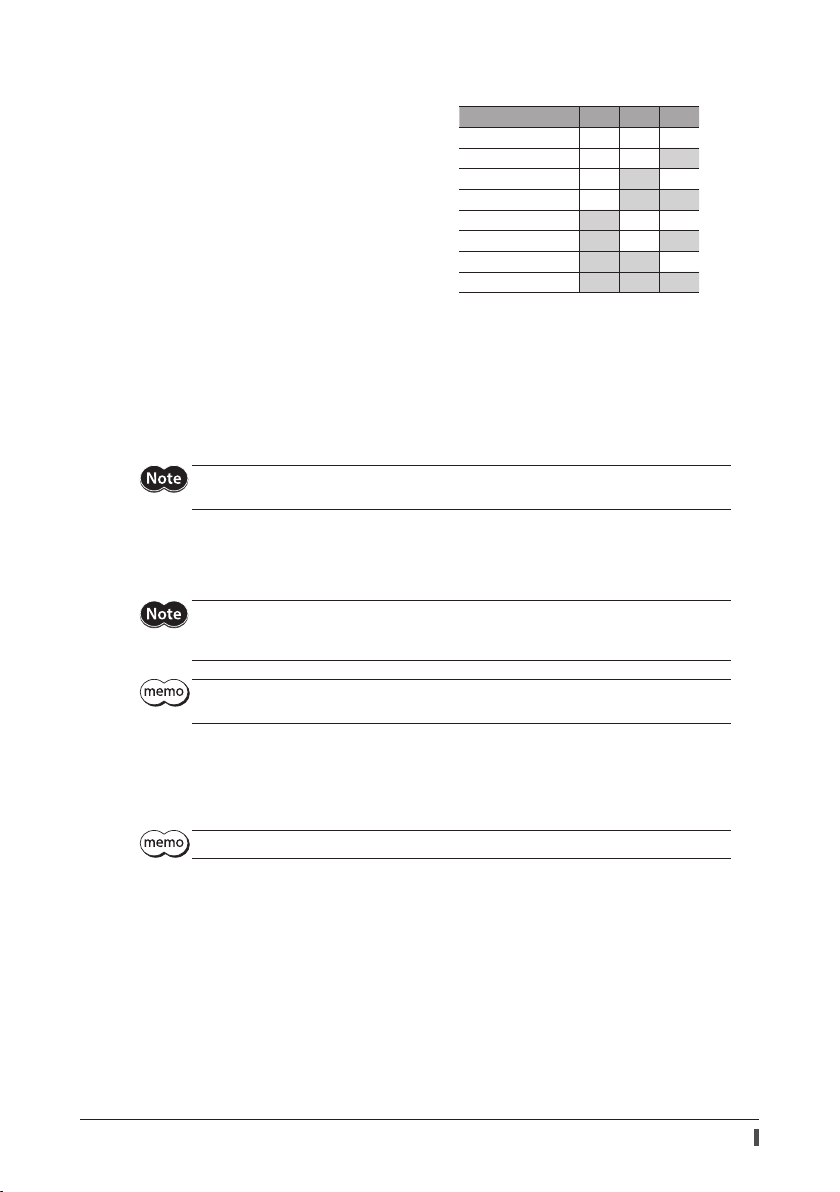
Base current rate
Set the base current rate (%) for the operating current and standstill current using the current setting switch
(CURRENT). If the load is small and there is an ample allowance for torque, motor temperature rise can be suppressed
by setting a lower base current rate.
The actual operating current and standstill current are as follows.
Operating current: Maximum output current × Base current rate
Standstill current: Maximum output current × Base current rate × 0.5
The dial settings and corresponding base current rates are listed below.
Dial setting Base current rate (%) Dial setting Base current rate (%)
0 6.3 8 56.3
1 12.5 9 62.5
2 18.8 A 68.8
3 25.0 B 75.0
4 31.3 C 81.3
5 37.5 D 87.5
6 43.8 E 93.8
7 50.0 F 100 (factory setting)
Excessively low operating current or standstill current may cause a problem in starting the motor or
holding the load in position. Set a suitable current for your application.
The motor torque is proportional to the current. If the CURRENT switch is set to "7" (50%) while the
operating torque is set to 100% (maximum output current), only 50% of the torque is output.
Base current rate 100%
Base current rate 50%
Torque [N•m]
Rotation speed [r/min]
Command lter
The motor response to input pulses can be adjusted using the command lter setting switch (FIL).
When setting a higher value for the command lter, lower vibration at low speed operation or smoother operation at
starting/stopping of the motor can be achieved. However, if this setting is too high, synchronization performance is
decreased. Set a suitable value based on the load or application.
The dial settings and corresponding command lter time constant are listed below.
Dial setting
Command lter time
constant (ms)
00 830
1 1 (factory setting) 9 50
22 A70
3 3 B 100
4 5 C 120
5 7 D 150
6 10 E 170
7 20 F 200
Dial setting
34
Command lter time
constant (ms)
Page 35

10 Guidance
If you are new to the AZ Series, read this section to understand the operating methods along with the operation ow.
How to read the guidance
This chapter explains the operation procedure as follows.
Connection (p.35)
* Perform the home position setting only once
initially. Once the home position is set, it is no
need to set afterward.
+24V 0V
PC in which the MEXE02
p.38)
p.36) *
p.40)
p.41)
Home position setting (
Trial operation (
Positioning operation (
High-speed return-to-home operation (
10-1 Connection
Wire the driver by reference to the gure. Be sure to connect a control power supply (24 VDC).
The following explanation is an example for when the built-in controller type driver of single-phase 200-240 VAC is
used.
Required
Control power
supply (24 VDC)
CN1 connector
Connect to +24V, 0V
Connect to ENCODER
Cable for encoder
Connect to MOTOR
Cable for motor
Required
Guidance
has been installed
Main power supply
Single-phase 200-240 VAC
Move the motor to a desired
home position manually.
* Cables represented in gray color are accessories. Use the cable for encoder when the length of the encoder cable of
motor is not enough.
Grounding
35
Page 36

Guidance
10-2 Home position setting
The home position has not set at the time of shipment. Before starting operation, be sure to set the home position.
Perform the home position setting only once initially. Once the home position is set, the driver keeps the home
information even if the power supply is shut down.
There are the following two methods for how to set the home position. Set the home position using either of the
methods.
Set the home position using the HOME PRESET switch on the driver.
Set the home position using the
The home position is written to the non-volatile memory. The non-volatile memory can be
rewritten approximately 100,000 times.
The home position for motorized actuators has been set at the time of shipment. Set the home
position only when you want to change it.
Set the home position using the HOME PRESET switch
1. Move the motor output shaft to a desired home position
manually.
2. Turn on the main power supply and control power supply
(24 VDC).
3. Check the power was turned ON, keep pressing the HOME
PRESET switch for one second.
Red color and green color on the PWR/ALM LED blinks
simultaneously. (Red and green colors may overlap and it
may be visible to orange.)
4. Release a hand o within three seconds after the PWR/ALM
LED started blinking, and press the HOME PRESET switch
again within three seconds after releasing the hand o .
After both red color and green color on the PWR/ALM LED
are lit, only green color continues to be lit.
MEXE02
.
PWR/ALM LED
HOME PRESET switch
PWR/ALM LED
HOME PRESET switch
5. The home position is set.
About an operation of the procedure 4, be sure to release a hand o after the PWR/ALM LED started
blinking, and perform within three seconds. If three seconds were passed, the PWR/ALM LED will
return to the state being lit in green. In this case, perform from the procedure 3 again.
Set the home position using the
1. Turn on the main power supply and control power supply (24 VDC).
2. Start a PC, and continuously start the
3. Click the [Teaching, remote operation] icon in the toolbar or click the [Teaching, remote operation] short-cut
button.
The teaching, remote operation window appears.
or
MEXE02
MEXE02
.
36
Page 37

4. Click "Start the teaching remote operation."
The pop-up window (Warning) appears, and click [Yes].
Guidance
5. Since the window which uses to synchronize the
synchronization method and click [OK].
Teaching, remote operation is enabled, and red color and green color on the PWR/ALM LED blink simultaneously.
(Red and green colors may overlap and it may be visible to orange.)
6. Adjust the motor position using the JOG operation switches.
JOG operation switches
Description of JOG operation switches
Switch Description
data and the driver data appears, select the
MEXE02
Performs continuous operation in the negative direction at the operating speed set in the "(JOG)
Operating speed (high)" parameter.
Performs continuous operation in the negative direction at the operating speed set in the "(JOG)
Operating speed" parameter.
Performs positioning operation in the negative direction for the travel amount set in the
"minimum travel amount" of the JOG operation switches.
Stops the operation immediately.
Performs positioning operation in the positive direction for the travel amount set in the
"minimum travel amount" of the JOG operation switches.
Performs continuous operation in the positive direction at the operating speed set in the "(JOG)
Operating speed" parameter.
Performs continuous operation in the positive direction at the operating speed set in the "(JOG)
Operating speed (high)" parameter.
37
Page 38

Guidance
7. When adjusting the motor position manually, click [FREE: ON] rst, and click [Yes] on the pop-up window
(Warning).
The holding power of the motor output shaft is lost, and the output shaft can be turned by hand.
After adjustment, click [FREE: OFF], and recover the motor excitation.
8. After setting the motor home position, click [Position Preset], and click [Yes] on the pop-up window (Warning).
The home position is set and written to the driver.
10-3 Trial operation
This section explains an example to perform trial operation using the
Before operating the motor, check the condition of the surrounding area to ensure safety.
1. Click the [Teaching, remote operation] icon in the toolbar or click the [Teaching, remote operation] short-cut
button.
The teaching, remote operation window appears.
or
2. Click "Start the teaching remote operation."
The pop-up window (Warning) appears, and click [Yes].
Teaching, remote operation is enabled, and red color and green color on the PWR/ALM LED blink simultaneously.
(Red and green colors may overlap and it may be visible to orange.)
3. Click the JOG operation switches to perform trial operation of the motor.
JOG operation switches
38
MEXE02
.
Page 39

Description of JOG operation switches
Switch Description
Performs continuous operation in the negative direction at the operating speed set in the "(JOG)
Operating speed (high)" parameter.
Performs continuous operation in the negative direction at the operating speed set in the "(JOG)
Operating speed" parameter.
Performs positioning operation in the negative direction for the travel amount set in the
"minimum travel amount" of the JOG operation switches.
Stops the operation immediately.
Performs positioning operation in the positive direction for the travel amount set in the
"minimum travel amount" of the JOG operation switches.
Performs continuous operation in the positive direction at the operating speed set in the "(JOG)
Operating speed" parameter.
Performs continuous operation in the positive direction at the operating speed set in the "(JOG)
Operating speed (high)" parameter.
If the motor does not operate even when clicking the JOG operation switches, check the following points.
· Are the power supply, motor, and
· Is an alarm present?
MEXE02
When changing the operating condition of JOG operation
1. Click on “Motor & Mechanism(Coordinates/JOG/Home Operation)” under “Parameter,” in the left side of the screen.
The “Motor & mechanism” parameter window appears.
Guidance
connected properly?
2. Change the "JOG/HOME/ZHOME operation setting" parameter to "manual setting."
3. Change the operating condition using following ve parameters.
4. After changing the operating condition, click the [Writing data] icon in the toolbar to download to the driver.
39
Page 40

Guidance
10-4 Positioning operation
This section explains an example to perform positioning operation using the
When using the pulse input type, set operation data to the programmable controller to perform operation.
Before operating the motor, check the condition of the surrounding area to ensure safety.
STEP 1 Set the operation data using the
Using the
Speed
2,000 [Hz]
500 [Hz]
, set the operation data of No.0 as follows.
MEXE02
8,500 [step]
1.5 [kHz/s]
1 [s] 1 [s]3 [s]
1.5 [kHz/s]
MEXE02
Time
MEXE02
Operation data setting screen
Input in increments of 0.001 kHz/s.
STEP 2 Operate the motor
1. Click the [Teaching, remote operation] icon in the toolbar or click the [Teaching, remote operation] short-cut
button.
The teaching, remote operation window appears.
or
.
2. Click "Start the teaching remote operation."
The pop-up window (Warning) appears, and click [Yes].
Teaching, remote operation is enabled, and red color and green color on the PWR/ALM LED blink simultaneously.
(Red and green colors may overlap and it may be visible to orange.)
40
Page 41

3. Write the edited data to the driver. Click "Writing all data. (PC −> Product)," and click [OK].
The contents of the data No.0 will be written to the driver.
4. Click [Start positioning operation].
The pop-up window (Warning) appears, and click [Yes].
The motor performs positioning operation.
10-5 High-speed return-to-home operation
Using high-speed return-to-home operation (ZHOME) can return the motor position to the home position easily.
STEP 1 Check the present position
Check the “Command position” in the teaching, remote operation window.
Guidance
STEP 2 Execute high-speed return-to-home operation
1. Click "ZHOME operation."
The pop-up window (Warning) appears, and click [Yes].
The motor will start high-speed return-to-home operation.
41
Page 42

Guidance
2. After the motor returns to the home position, check that the "Command position" is 0.
When changing the operating condition of high-speed return-to-home operation
1. Click on “Motor & Mechanism(Coordinates/JOG/Home Operation)” under “Parameter,” in the left side of the screen.
The “Motor & mechanism” parameter window appears.
2. Change the "JOG/HOME/ZHOME operation setting" parameter to "manual setting."
3. Change the operating condition using following three parameters.
4. After changing the operating condition, click the [Writing data] icon in the toolbar to download to the driver.
STEP 3 End the teaching, remote operation
To end the teaching, remote operation, unselect “Start the teaching remote operation.”
42
Page 43

10-6 Timing chart
This section shows ON/OFF timings for input signals and output signals.
For details, check with the AZ Series Function Edition.
Positioning operation
Built-in controller type
Positioning operation can be performed with selecting the operation data.
1. Turn on the control power supply (24 VDC) and main power supply.
The READY output will turn ON.
2. Check the READY output is turned ON and turn the START input ON by selecting the operation data number with
the M0 to M2 outputs.
The motor starts positioning operation.
3. Check the READY output has been turned OFF and turn the START input OFF.
When the operation is complete, the READY output will turn ON.
1
Control power supply (24 VDC)
Main power supply
M0 to M2 input
START input
READY output
MOVE output
IN-POS output
OFF
OFF
OFF
OFF
OFF
OFF
OFF
ON
ON
ON
ON
ON
ON
ON
1
Guidance
2
3
3
Motor operation
43
Page 44

Guidance
Pulse input type with RS-485 communication interface, pulse input type
Positioning operation is performed by inputting pulses.
1. Turn on the control power supply (24 VDC) and main power supply.
The READY output and PLS-RDY output will turn ON.
2. Check the PLS-RDY output has been turned ON and input pulses.
The motor starts positioning operation.
When the pulse is stopped inputting and the operation is complete, the READY output will turn ON.
1
Control power supply (24 VDC)
Main power supply
Pulse input
READY output
PLS-RDY output
MOVE output
IN-POS output
OFF
OFF
OFF
OFF
OFF
OFF
OFF
ON
ON
ON
ON
ON
ON
ON
1
2
2
Motor operation
When using in the 1-pulse input mode.
Perform the following settings beforehand when using in the 1-pulse input mode.
Pulse input type with RS-485 communication interface;
1. Click on “Communication I/F function” under “Parameter,” in the left side of the screen.
The “Communication I/F function” parameter window appears.
2. Set the "PULSE-I/F mode selection" parameter to "1-PULSE."
3. After changing the operating condition, click the [Writing data] icon in the toolbar to download to the driver.
4. Cycle the power supply of the driver.
The changed parameter is applied.
44
Page 45

Pulse input type;
1. Set the SW1-No.2 to ON.
2. Cycle the power supply of the driver.
The changed setting is enabled.
High-speed return-to-home operation (ZHOME operation)
High-speed return-to-home operation is used to return to the home position that is set by the
PRESET switch.
1. Turn on the control power supply (24 VDC) and main power supply.
The READY output and PLS-RDY output will turn ON.
2. Check the READY output has been turned ON and turn the ZHOME input ON.
The READY output will turn OFF, and the motor will start high-speed return-to-home operation.
3. Check the READY output has been turned OFF and turn the ZHOME input OFF.
When the home position is detected, the operation will be stopped.
The HOME-END output and READY output will turn ON.
1
Control power supply (24 VDC)
Main power supply
ZHOME input
HOME-END output
READY output
PLS-RDY output
MOVE output
OFF
OFF
OFF
OFF
OFF
OFF
OFF
ON
ON
ON
ON
ON
ON
ON
1
223
3
MEXE02
Guidance
or HOME
Motor operation
45
Page 46

Guidance
JOG operation
Constant speed operation can be performed with JOG operation. The motor operates continuously while the FW-JOG
input or RV-JOG input is being ON.
1. Turn on the control power supply (24 VDC) and main power supply.
The READY output and PLS-RDY output will turn ON.
2. Check the READY output has been turned ON and turn the FW-JOG input or RV-JOG input ON.
The motor will start operation.
When the FW-JOG input is turned ON, the motor rotates in the forward direction, and when the RV-JOG input is
turned ON, the motor rotates in the reverse direction.
3. Turn the input signal OFF.
The motor will decelerate to a stop. When the motor stops, the READY output will turn ON.
1
Control power supply (24 VDC)
Main power supply
FW-JOG input or
RV-JOG input
READY output
PLS-RDY output
IN-POS output
MOVE output
Motor operation
OFF
OFF
OFF
OFF
OFF
OFF
OFF
ON
ON
ON
ON
ON
ON
ON
1
2 3
2
46
Page 47

Power removal function (ETO function: External Torque O )
11 Power removal function
(ETO function: External Torque O )
The power removable function (ETO function: External Torque O function) is the one that stops supplying the power
to the motor forcibly to put the motor into a non-excitation state if the HWTO input of the CN1 is shut o . This
function, which is di erent from the FREE input, shuts o the power supply to the motor directly on the circuit.
It can be used for the purpose of preventing dangerous movements of the moving part when maintenance of the
equipment is performed.
Related I/O signals are the HWTO input and EDM output.
Be sure to check the motor is in a standstill state before executing the ETO function. If the ETO
function is executed while the motor is operated, it may cause damage to the motor, driver, or
equipment.
11-1 Block diagram
Main power
supply
Motor
HWTO1+
HWTO1
HWTO2+
HWTO2
4.7 kΩ
-
4.7 kΩ
-
EDM+
-
EDM
Signal name Speci caion
HWTO1+ input, HWTO1− input
HWTO2+ input, HWTO2− input
EDM+ output, EDM− output
HWTO1
HWTO2
EDM
24 VDC±10%
30 VDC or less, 50 mA or less
Output saturated voltage 1.1 V
ASIC
11-2 Related I/O signals
HWTO input
When either of the HWTO1 input or HWTO2 input is turned OFF, the power to the motor is cut o by the electronic
circuit without involving the CPU, causing the motor to stop. In this time, the PWR/ALM LED will blink in green.
When an electromagnetic brake motor is used, the electromagnetic brake continues to hold the position.
47
Page 48

Power removal function (ETO function: External Torque O )
EDM output
If both the HWTO1 input and HWTO2 input are turned OFF, the EDM output will turn ON.
HWTO1 input HWTO2 input EDM output Motor excitation
ON ON OFF Excitation
ON OFF OFF
Non-excitationOFF ON OFF
OFF OFF ON
11-3 Releasing ETO state
If the STOP input is turned ON while the ETO function is activated, the ETO state can be released (e ective at the ON
edge of the STOP input). Be sure to turn the STOP input ON after turning the HWTO1 input and HWTO2 input ON.
11-4 Timing chart
Be sure to check the motor is in a standstill state before executing the ETO function. If the ETO
function is executed while the motor is operated, it may cause damage to the motor, driver, or
equipment.
1. When both the HWTO1 input and HWTO2 input have been turned OFF, the EDM output will turn ON.
The power supply to the motor will be shut o .
2. Turn the HWTO1 input and HWTO2 input ON.
3. Turn the STOP input ON.
The power is supplied to the motor, and the motor will be excited.
4. Turn the STOP input OFF.
The PLS-RDY input turns ON, and the driver will be ready to operate.
21
3 4
200 ms or less
HWTO1 input
HWTO2 input
EDM output
STOP input
READY output
PLS-RDY output
Motor excitation
Electromagnetic brake
OFF
OFF
OFF
OFF
OFF
OFF
Hold
Release
ON
10 ms or less 10 ms or less
ON
ON
10 ms or less
ON
10 ms or less
ON
ON
2 ms or more
2 ms or less
2 ms or less
250 ms or less
48
Page 49

Power removal function (ETO function: External Torque O )
11-5 To use this product safely
When the ETO function is used, be sure to conduct a risk assessment of equipment in advance to
satisfy the safety requirements of the entire system.
The ETO function is designed based on the assumption that the motor is in a standstill state. Do not
execute the ETO function while the motor is rotating.
Even if the ETO function is activated, the following potential risks can be estimated. Be sure to con rm
the safety by conducting a risk assessment.
The motor output shaft may be rotated by an external force. If the motor output shaft is kept in place, install an
external brake mechanism or equivalent. Do not use the brake mechanism of the electromagnetic brake motor for
braking the motor rotation.
If the ETO function is activated, the driver stops supplying the power to the motor. However, the input power to
the driver is not shut o , and the driver is not electrically isolated. Before performing maintenance or inspection,
always turn o the driver power, and check the voltage with a circuit tester after the CHARGE LED is turned o .
The EDM output is not an output signal to ensure the safety. Do not use the EDM output for any other
purpose except for monitoring a failure.
49
Page 50

Inspection
12 Inspection
It is recommended that periodic inspections be conducted for the items listed below after each operation of the
motor. If an abnormal condition is noted, discontinue any use and contact your nearest Oriental Motor sales o ce.
During inspection
Are the openings in the driver blocked?
Are any of the mounting screws or connection parts of the driver loose?
Is there attachment of dust, etc., on the driver?
Are there any strange smells or appearances within the driver?
The driver uses semiconductor elements, so be extremely careful when handling them. Static
electricity may damage the driver.
50
Page 51

13 Alarm (protective function)
When an alarm generates, the ALM-B output will turn OFF and PWR/ALM LED will blink in red.
Before resetting an alarm, always remove the cause of the alarm and ensure safety.
If the motor cannot be operated properly after resetting the alarm, the driver may have been damaged.
For details about alarms, refer to the AZ Series Function Edition.
Reset alarm
Cycle the power supply of the driver.
Click [Alarm Reset] on the
MEXE02
.
Alarm (protective function)
Example of the alarm monitor screen of the
The alarm message can be checked using the "Alarm monitor" of the
MEXE02
MEXE02
.
Resets the alarm.
The measures are
displayed.
The cause that generated
the alarm is displayed.
51
Page 52

Troubleshooting
14 Troubleshooting
During motor operation, the motor or driver may fail to function properly due to an improper setting or wiring. When
the motor cannot be operated correctly, refer to the contents provided in this section and take appropriate action. If
the problem persists, contact your nearest Oriental Motor sales office.
This chapter describes problems that may occur during operation in addition to the initial settings.
Phenomenon Possible cause Remedial action
The motor is not excited.
The motor output shaft can
be moved by hand.
The motor does not operate.
The motor does not rotate
although the READY LED is lit.
(only for pulse-input type)
The motor rotates in the
direction opposite to the
speci ed direction.
The gear output shaft rotates in
the direction opposite to the
motor.
Motor operation is unstable.
Motor vibration is too great. Load is too small.
The electromagnetic brake
does not release.
Refer to the AZ Series Function Edition for these contents.
Connection error in the motor
cable.
The FREE input is turned ON. Turn the FREE input OFF.
An electromagnetic brake motor is
used and the electromagnetic
brake is in the holding state.
The STOP input is turned ON. Turn the STOP input OFF.
The position (distance) is not set in
the operation data while
positioning operation.
The FW-JOG input and RV-JOG
input are turned ON simultaneously
in the JOG operation.
Signals are not connected
properly.
Multiple signals have been input
simultaneously.
The "motor rotation direction"
parameter is set wrong.
A gear that rotates in the direction
opposite to the motor shaft is used.
Connection error in the motor or
power supply.
The base current rate setting is too
low.
The power is not supplied to the
electromagnetic brake.
Check the connections between the driver and motor.
Check the connections between electromagnetic
brake and driver.
Check the operation data.
After turning both the FW-JOG input and RV-JOG input
OFF, turn either one of them ON.
Wire signals correctly.
Check if the signal line is disconnected.
Check if the wrong signal is input.
Check the setting of the "motor rotation direction"
parameter.
With TS geared motor, the gear output shaft rotates
in the direction opposite to the motor when the gear
ratio is 20 or 30.
With Harmonic geared motors, the gear output shaft
always rotates in the direction opposite to the motor.
Check the connections between the driver, motor and
power supply.
Return the CURRENT switch to its initial setting and
check. If the current is too low, the motor torque will
also be too low and operation will be unstable.
Built-in controller type, pulse input type with RS-485
communication interface;
Lower the current using the "Base current"
parameter. Vibration will increase if the motor’s
output torque is too large for the load.
Pulse input type;
Lower the current using the CURRENT switch.
Vibration will increase if the motor’s output torque is
too large for the load.
Check the connection of the electromagnetic brake.
Check the alarm message using the
I/O signals can be monitored using the
signals.
when the alarm generates.
MEXE02
. Use to check the wiring condition of the I/O
MEXE02
52
Page 53

To use the product in more convenient manners
15 To use the product in more convenient
manners
Using the
can monitor the operating status or perform test operation.
Refer to the AZ Series Function Edition for details about operation.
Like to set the resolution
based on the function
Like to utilize convenient
functions for maintenance
push-motion operation
, you can set the operation data or change I/O signals that assign to the CN5 connector. Also, you
MEXE02
Like to perform
Like to change the I/O
assignment
Like to check operation
by the waveform monitor
Like to operate
via industrial network *
Like to utilize the
sequence function
Like to change the
alarm conditions
* Excluding the pulse input type.
53
Page 54

Accessories
16 Accessories
16-1 Motor cable set
Connection cable set
This is a cable set needed when a motor and driver are connected. It is a set of two cables for the motor and encoder.
For the cable set of electromagnetic brake motors, a set of three cables for the motor, encoder and electromagnetic
brake is provided.
Connection cable
For electromagnetic brake *
For encoder
For motor
* Only when the motor is of electromagnetic brake type.
When installing the motor on a moving part, use a exible cable having excellent ex resistance.
54
Page 55

Connection cable set
For standard type motor For electromagnetic brake type motor
Model Length [m (ft.)] Model Length [m (ft.)]
CC005VZF
CC010VZF
CC015VZF
CC020VZF
CC025VZF
CC030VZF
CC040VZF
CC050VZF
CC070VZF
CC100VZF
CC150VZF
CC200VZF
0.5 (1.6)
1 (3.3)
1.5 (4.9)
2 (6.6)
2.5 (8.2)
3 (9.8)
4 (13.1)
5 (16.4)
7 (23.0)
10 (32.8)
15 (49.2)
20 (65.6)
CC005VZFB
CC010VZFB
CC015VZFB
CC020VZFB
CC025VZFB
CC030VZFB
CC040VZFB
CC050VZFB
CC070VZFB
CC100VZFB
CC150VZFB
CC200VZFB
0.5 (1.6)
1 (3.3)
1.5 (4.9)
2 (6.6)
2.5 (8.2)
3 (9.8)
4 (13.1)
5 (16.4)
7 (23.0)
10 (32.8)
15 (49.2)
20 (65.6)
Flexible connection cable set
For standard type motor For electromagnetic brake type motor
Model Length [m (ft.)] Model Length [m (ft.)]
CC005VZR
CC010VZR
CC015VZR
CC020VZR
CC025VZR
CC030VZR
CC040VZR
CC050VZR
CC070VZR
CC100VZR
CC150VZR
CC200VZR
0.5 (1.6)
1 (3.3)
1.5 (4.9)
2 (6.6)
2.5 (8.2)
3 (9.8)
4 (13.1)
5 (16.4)
7 (23.0)
10 (32.8)
15 (49.2)
20 (65.6)
CC005VZRB
CC010VZRB
CC015VZRB
CC020VZRB
CC025VZRB
CC030VZRB
CC040VZRB
CC050VZRB
CC070VZRB
CC100VZRB
CC150VZRB
CC200VZRB
0.5 (1.6)
1 (3.3)
1.5 (4.9)
2 (6.6)
2.5 (8.2)
3 (9.8)
4 (13.1)
5 (16.4)
7 (23.0)
10 (32.8)
15 (49.2)
20 (65.6)
Accessories
55
Page 56

Accessories
Extension cable set
This is a cable set needed when a motor and driver are relayed. It is a set of two cables for the motor and encoder.
For the cable set of electromagnetic brake motors, a set of three cables for the motor, encoder and electromagnetic
brake is provided.
Extension cable
Connection cable *1
For electromagnetic brake *2
For encoder For encoder
For motor
When installing the motor on a moving part, use a exible cable having excellent ex resistance.
When extending the wiring length by connecting an extension cable to the connection cable,
keep the total cable length to 20 m (65.6 ft.) or less.
For electromagnetic brake *2
For motor
*1 Use the connection cable used.
*2 Only when the motor is of electromagnetic brake type.
Extension cable set
For standard type motor For electromagnetic brake type motor
Model Length [m (ft.)] Model Length [m (ft.)]
CC010VZFT
CC020VZFT
CC030VZFT
CC050VZFT
CC070VZFT
CC100VZFT
CC150VZFT
1 (3.3)
2 (6.6)
3 (9.8)
5 (16.4)
7 (23.0)
10 (32.8)
15 (49.2)
CC010VZFBT
CC020VZFBT
CC030VZFBT
CC050VZFBT
CC070VZFBT
CC100VZFBT
CC150VZFBT
1 (3.3)
2 (6.6)
3 (9.8)
5 (16.4)
7 (23.0)
10 (32.8)
15 (49.2)
Flexible extension cable set
For standard type motor For electromagnetic brake type motor
Model Length [m (ft.)] Model Length [m (ft.)]
CC010VZRT
CC020VZRT
CC030VZRT
CC050VZRT
CC070VZRT
CC100VZRT
CC150VZRT
1 (3.3)
2 (6.6)
3 (9.8)
5 (16.4)
7 (23.0)
10 (32.8)
15 (49.2)
CC010VZRBT
CC020VZRBT
CC030VZRBT
CC050VZRBT
CC070VZRBT
CC100VZRBT
CC150VZRBT
56
1 (3.3)
2 (6.6)
3 (9.8)
5 (16.4)
7 (23.0)
10 (32.8)
15 (49.2)
Page 57

16-2 Driver cable
This cable is a shielded cable for good noise immunity in order to connect the I/O signals of the controller to the
driver. The ground wires useful to grounding are provided at both ends of the cable. A connector is assembled at the
driver side.
Model Length [m (ft.)] Number of poles Type
CC24D005C-1
CC24D010C-1
CC24D020C-1
0.5 (1.6)
1 (3.3)
2 (6.6)
24 Single-row
16-3 RS-485 communication cable
This cable is necessary when connecting two or more drivers of the built-in controller type or the pulse input type
with RS-485 communication interface.
It can connect between drivers by connecting to the CN6 and CN7 connectors. Also, it can be used when connecting
the driver and the network converter.
Model:
CC002-RS4
[0.25 m (0.8 ft.)]
16-4 Wiring support tool
Pulse signal converter for noise immunity
It eliminates the noise of the pulse signal and changes the pulse signal to the line driver type.
Model:
VCS06
CR circuit for surge suppression
This product is e ective to suppress the serge which occurs in a relay contact part. Use it to protect the contacts of
the relay or switch.
Model:
EPCR1201-2
Accessories
CR circuit module
This product is e ective to suppress the surge which occurs in a relay contact part. Use this product to protect the
contacts of the relay or switch.
4 pieces of CR circuit for surge suppression are mounted on the compact circuit, and this product can be installed to
the DIN rail. This product can make the wiring easily and securely since it also supports terminal block connection.
Model:
VCS02
Regeneration unit
Connect the regeneration unit if gravitational operation or other operations involving up/down movement, or sudden
starting/stopping of a large inertial load, will be repeated frequently.
Always connect the regeneration unit if an overvoltage protection warning or alarm generates.
Model:
RGB100
57
Page 58

58
Page 59

59
Page 60

Unauthorized reproduction or copying of all or part of this Operating Manual is prohibited.
T
T
T
T
If a new copy is required to replace an original manual that has been damaged or lost, please contact your nearest Oriental
Motor branch or sales o ce.
Oriental Motor shall not be liable whatsoever for any problems relating to industrial property rights arising from use of any
information, circuit, equipment or device provided or referenced in this manual.
Characteristics, speci cations and dimensions are subject to change without notice.
While we make every e ort to o er accurate information in the manual, we welcome your input. Should you nd unclear
descriptions, errors or omissions, please contact the nearest o ce.
and other countries.
Other product names and company names mentioned in this manual may be registered trademarks or trademarks of their
respective companies and are hereby acknowledged. The third-party products mentioned in this manual are recommended
products, and references to their names shall not be construed as any form of performance guarantee. Oriental Motor is not
liable whatsoever for the performance of these third-party products.
© Copyright ORIENTAL MOTOR CO., LTD. 2016
,
, and ABZO sensor are registered trademark or trademark of Oriental Motor Co., Ltd., in Japan
Published in February 2018
• Please contact your nearest Oriental Motor oce for further information.
Technical Support Tel:(800)468-3982
A.M. to 5:00 P.M., P.S.T. (M-F)
8:30
7:30
A.M. to 5:00 P.M., C.S.T. (M-F)
www.orientalmotor.com
el:+55-11-3266-6018
www.orientalmotor.com.br
Schiessstraße 44, 40549 Düsseldorf, Germany
echnical Support Tel:00 800/22 55 66 22
www.orientalmotor.de
el:01256-347090
www.oriental-motor.co.uk
el:01 47 86 97 50
www.orientalmotor.fr
Tel:02-93906346
www.orientalmotor.it
Singapore
Tel:1800-8420280
www.orientalmotor.com.sg
Tel:1800-806161
www.orientalmotor.com.my
Tel:1800-888-881
www.orientalmotor.co.th
Tel:+91-80-41125586
www.orientalmotor.co.in
Tel:0800-060708
www.orientalmotor.com.tw
Tel:400-820-6516
www.orientalmotor.com.cn
Korea
Tel:080-777-2042
www.inaom.co.kr
Hong Kong Branch
Tel:+852-2427-9800
4-8-1 Higashiueno, Taito-ku, Tokyo
110-8536 Japan
Tel:03-6744-0361
www.orientalmotor.co.jp
 Loading...