

Page 1

Stepping Motor and Driver Package
HM-60262-6
Before starting operation
Operation
AZ
Series/
Motorized actuator
equipped the
AZ
Series
Function Edition
I/O signals
Parameter
Method of control via
Modbus RTU
(RS-485 communication)
Method of control via
industrial network
Address list
Measures for various
cases
Alarm and information
Thank you for purchasing an Oriental Motor product.
This Manual describes product handling procedures and safety precautions.
•Please read it thoroughly to ensure safe operation.
•Always keep the manual where it is readily available.
Extended setting for
pulse-input operation
Appendix
Page 2

1 Characteristics of the AZ Series ..........................................................................................................................10
2 Operations possible with the AZ Series ............................................................................................................12
3 Types and overview of driver .............................................................................................................................. 14
4 How to use OPERATING MANUALS for product ...............................................................................................16
5 Expansion of supported contents ......................................................................................................................18
1 Before starting operation
1 Steps of preparation for operation ....................................................................................................................20
2 Starting the
MEXE02
...........................................................................................................................................21
3 Copying the xed value (parameter) of the ABZO sensor to driver .............................................................22
4 Creation of recovery data le and method of recovery ................................................................................. 24
4-1 Creating the recovery data le ....................................................................................................................................................... 24
4-2 Method of recovery ............................................................................................................................................................................ 26
5 Setting of display unit and resolution ...............................................................................................................29
5-1 Setting example for when an index table is used ................................................................................................................... 29
5-2 Setting example for when a linear mechanism is assembled ............................................................................................. 32
6 Home position setting ..........................................................................................................................................36
7 Wrap setting ...........................................................................................................................................................39
8 Setting of software limit ......................................................................................................................................44
9 Operation check ....................................................................................................................................................47
10 Backup of data .......................................................................................................................................................50
2 Operation
1 Flow of setting required for positioning operation ........................................................................................ 52
2 Setting of resolution .............................................................................................................................................53
3 Stored data (SD) operation ..................................................................................................................................55
3-1 Types of stored data (SD) operation ............................................................................................................................................. 55
3-2 Setting of data ...................................................................................................................................................................................... 59
3-3 Positioning SD operation ................................................................................................................................................................. 66
3-4 Positioning push-motion SD operation ...................................................................................................................................... 75
3-5 Continuous SD operation ................................................................................................................................................................. 78
3-6 Mode for link operation of operation data ................................................................................................................................ 83
3-7 Sequence function .............................................................................................................................................................................. 93
3-8 Extended operation data setting .................................................................................................................................................. 99
3-9 Stop operation ...................................................................................................................................................................................101
3-10 Base current and stop current ......................................................................................................................................................103
3-11 Acceleration/deceleration unit ....................................................................................................................................................104
3-12 Starting speed ....................................................................................................................................................................................104
2
Page 3

4 Return-to-home operation ................................................................................................................................105
4-1 High-speed return-to-home operation .....................................................................................................................................105
4-2 Return-to-home operation ............................................................................................................................................................107
5 Macro operation ..................................................................................................................................................121
5-1 Types of macro operation ..............................................................................................................................................................121
5-2 JOG operation.....................................................................................................................................................................................122
5-3 High-speed JOG operation ............................................................................................................................................................124
5-4 Inching operation .............................................................................................................................................................................126
5-5 Combined JOG operation ..............................................................................................................................................................128
5-6 Continuous operation .....................................................................................................................................................................130
5-7 Speed control operation .................................................................................................................................................................132
5-8 Speed control push-motion operation .....................................................................................................................................134
6 Relationship between operation type and operation data and parameter .............................................136
7 Position coordinate management ...................................................................................................................140
7-1 Overview of position coordinate management .....................................................................................................................140
7-2 Position coordinate origin ..............................................................................................................................................................144
7-3 Parameters related to ABZO sensor ............................................................................................................................................145
7-4 Mechanism settings parameter ...................................................................................................................................................146
7-5 Initial coordinate generation & wrap coordinate parameter ............................................................................................147
7-6 Mechanism limit ...............................................................................................................................................................................152
7-7 Mechanism protection ....................................................................................................................................................................152
7-8 Position coordinate information monitor function ..............................................................................................................153
3 I/O signals
1 Overview of I/O signals ......................................................................................................................................158
1-1 Overview of input signals...............................................................................................................................................................158
1-2 Overview of output signals ...........................................................................................................................................................159
1-3 Setting contents of input signals and output signals ..........................................................................................................160
2 Signal list ...............................................................................................................................................................165
2-1 Input signal list ...................................................................................................................................................................................165
2-2 Output signal list ...............................................................................................................................................................................167
3 Signal types ..........................................................................................................................................................172
3-1 Direct I/O ..............................................................................................................................................................................................172
3-2 Remote I/O ...........................................................................................................................................................................................181
4 Input signals .........................................................................................................................................................183
4-1 Operation control ..............................................................................................................................................................................183
4-2 Position coordinate management ..............................................................................................................................................202
4-3 Management of driver .....................................................................................................................................................................204
5 Output signals ......................................................................................................................................................207
5-1 Management of driver .....................................................................................................................................................................207
5-2 Management of operation .............................................................................................................................................................208
5-3 Latch information indication ........................................................................................................................................................217
5-4 Response output ...............................................................................................................................................................................218
3
Page 4

6 Timing chart .........................................................................................................................................................219
7 Power removal function (ETO function: External Torque O function) ....................................................222
7-1 Block diagram .....................................................................................................................................................................................222
7-2 Wiring example ..................................................................................................................................................................................223
7-3 Detection for error of the ETO function ....................................................................................................................................223
7-4 Reset of ETO-mode ...........................................................................................................................................................................224
7-5 Related parameters ..........................................................................................................................................................................224
7-6 Timing chart ........................................................................................................................................................................................225
7-7 For safe use ..........................................................................................................................................................................................227
4 Parameters
1 Parameter: Base setting .....................................................................................................................................230
2 Parameter: Motor and Mechanism (Coordinates/JOG/Home Operation) ................................................233
3 Parameter: ETO and Alarm and Info ................................................................................................................236
4 Parameter: I/O action and function .................................................................................................................239
5 Parameter: Direct-IN function ...........................................................................................................................244
6 Parameter: Direct-OUT function .......................................................................................................................245
7 Parameter: Remote-I/O function (R-I/O) .........................................................................................................246
8 Parameter: EXT-IN and VIR-IN and USR-OUT function (Extend) .................................................................248
9 Parameter: Communication & I/F .....................................................................................................................250
10 I/O signal assignment list ...................................................................................................................................256
10-1 Input signals ........................................................................................................................................................................................256
10-2 Output signals ....................................................................................................................................................................................257
5 Method of control via Modbus RTU (RS-485 communication)
1 Specication of Modbus RTU ............................................................................................................................260
1-1 Communication specications .....................................................................................................................................................260
1-2 Communication timing ...................................................................................................................................................................263
2 Message structure ...............................................................................................................................................264
2-1 Query .....................................................................................................................................................................................................264
2-2 Response ..............................................................................................................................................................................................266
3 Function codes .....................................................................................................................................................268
3-1 Reading from a holding register(s) (03h) ..................................................................................................................................268
3-2 Writing to a holding register (06h) ..............................................................................................................................................269
3-3 Diagnosis (08h) ..................................................................................................................................................................................270
3-4 Writing to multiple holding registers (10h) .............................................................................................................................271
3-5 Read/write of multiple holding registers (17h) ......................................................................................................................272
4 Flow of setting required for Modbus communication .................................................................................274
5 Guidance ...............................................................................................................................................................275
4
Page 5

6 Setting of switches ..............................................................................................................................................279
6-1 Protocol .................................................................................................................................................................................................279
6-2 Address number (slave address) ..................................................................................................................................................280
6-3 Transmission rate...............................................................................................................................................................................280
6-4 Termination resistor .........................................................................................................................................................................281
7 Setting of RS-485 communication ...................................................................................................................282
7-1 Parameters reected when turning on the power ................................................................................................................282
7-2 Parameters reected immediately after rewriting ................................................................................................................283
7-3 Forcible return of parameters to initial values (default function) ....................................................................................283
8 Example of data setting in Modbus RTU mode .............................................................................................284
8-1 Remote I/O command .....................................................................................................................................................................284
8-2 Positioning operation ......................................................................................................................................................................286
8-3 Continuous operation .....................................................................................................................................................................288
8-4 High-speed return-to-home operation .....................................................................................................................................292
9 Data setting method ...........................................................................................................................................294
9-1 Overview of setting method .........................................................................................................................................................294
9-2 Direct reference .................................................................................................................................................................................294
9-3 Indirect reference ..............................................................................................................................................................................295
10 Direct data operation .........................................................................................................................................302
10-1 Overview of direct data operation ..............................................................................................................................................302
10-2 Guidance ..............................................................................................................................................................................................303
10-3 Commands required for direct data operation ......................................................................................................................307
11 Group send ...........................................................................................................................................................312
12 Timing chart .........................................................................................................................................................314
12-1 Communication start .......................................................................................................................................................................314
12-2 Start of operation ..............................................................................................................................................................................314
12-3 Operation stop, speed change .....................................................................................................................................................314
12-4 General signals ...................................................................................................................................................................................315
12-5 Conguration ......................................................................................................................................................................................315
13 Detection of communication errors ................................................................................................................316
13-1 Communication errors ....................................................................................................................................................................316
13-2 Alarms related to RS-485 communication ...............................................................................................................................316
6 Method of control via industrial network
1 Flow of setting required for control via
industrial network ...............................................................................................................................................318
2 Setting of switches ..............................................................................................................................................319
2-1 Protocol .................................................................................................................................................................................................319
2-2 Address number (slave address) ..................................................................................................................................................320
2-3 Transmission rate...............................................................................................................................................................................320
2-4 Termination resistor .........................................................................................................................................................................320
5
Page 6

3 Method of control via CC-Link communication .............................................................................................322
3-1 Guidance ..............................................................................................................................................................................................322
3-2 Operation example of command selection method ............................................................................................................327
3-3 Operation example of command xation method ...............................................................................................................334
4 Method of control via EtherCAT communication ..........................................................................................340
4-1 Guidance ..............................................................................................................................................................................................340
4-2 Basic operating procedures ...........................................................................................................................................................345
5 Group function.....................................................................................................................................................348
5-1 Group address ....................................................................................................................................................................................349
5-2 Group action modes ........................................................................................................................................................................349
6 Simple direct data operation ............................................................................................................................352
6-1 Types of simple direct data operation .......................................................................................................................................352
6-2 How to use simple direct data operation monitor 0 ............................................................................................................353
6-3 How to use simple direct data operation monitor 1 ............................................................................................................355
7 Detection of communication errors ................................................................................................................357
7-1 Communication errors ....................................................................................................................................................................357
7-2 Alarms ....................................................................................................................................................................................................358
7 Address/code lists
1 Update timing of parameters ............................................................................................................................360
2 I/O commands ......................................................................................................................................................361
3 Group commands ................................................................................................................................................363
4 Protect release commands ................................................................................................................................364
5 Direct data operation commands ....................................................................................................................365
6 Simple direct data operation commands .......................................................................................................367
7 Maintenance commands....................................................................................................................................368
7-1 How to execute maintenance commands ...............................................................................................................................369
8 Monitor commands .............................................................................................................................................370
9 Overview of operation data R/W command address arrangement ...........................................................381
9-1 Overview of direct reference .........................................................................................................................................................382
9-2 Overview of oset reference .........................................................................................................................................................382
9-3 Overview of direct reference (compatible) ..............................................................................................................................382
10 Operation data R/W commands .......................................................................................................................383
10-1 Direct reference (Modbus communication) ............................................................................................................................383
10-2 Oset reference (Modbus communication) ............................................................................................................................388
10-3 Oset reference (industrial network) .........................................................................................................................................388
11 Operation data R/W commands (compatible) ...............................................................................................395
11-1 Direct reference (Modbus communication) ............................................................................................................................395
11-2 Direct reference (industrial network) .........................................................................................................................................396
6
Page 7

12 Operation I/O event R/W commands ...............................................................................................................398
12-1 Setting method ..................................................................................................................................................................................398
12-2 Direct reference .................................................................................................................................................................................398
12-3 Oset reference .................................................................................................................................................................................400
13 Extended operation data setting R/W commands ........................................................................................402
14 Parameter R/W commands ................................................................................................................................403
14-1 Driver action simulation setting parameter ............................................................................................................................403
14-2 Base setting parameters .................................................................................................................................................................403
14-3 Position coordinate parameters...................................................................................................................................................404
14-4 Operation parameters .....................................................................................................................................................................405
14-5 Direct data operation parameters ...............................................................................................................................................405
14-6 ABZO sensor setting parameters .................................................................................................................................................406
14-7 Mechanism settings parameters .................................................................................................................................................406
14-8 Initial coordinate generation & wrap coordinate parameters ..........................................................................................407
14-9 JOG/HOME/ZHOME operation information setting parameters .....................................................................................407
14-10 Power removal function setting parameters ..........................................................................................................................409
14-11 Alarm setting parameters ..............................................................................................................................................................409
14-12 Information setting parameters ...................................................................................................................................................409
14-13 I/O parameter .....................................................................................................................................................................................412
14-14 Direct I/O setting parameters .......................................................................................................................................................416
14-15 Remote I/O setting parameters ....................................................................................................................................................419
14-16 Extended input setting parameters ...........................................................................................................................................422
14-17 Dierential output setting parameters .....................................................................................................................................422
14-18 Virtual input parameters .................................................................................................................................................................423
14-19 User output setting parameters ...................................................................................................................................................424
14-20 Driver mode setting parameters .................................................................................................................................................424
14-21 LED status indication setting parameters ................................................................................................................................425
14-22 RS-485 communication setting parameters ............................................................................................................................425
14-23 Indirect reference setting parameters .......................................................................................................................................427
14-24 Our exclusive parameters for maintenance. ............................................................................................................................428
15 I/O signal assignment list ...................................................................................................................................429
15-1 Input signals ........................................................................................................................................................................................429
15-2 Output signals ....................................................................................................................................................................................430
8 Measures for various cases
1 Vibration suppression ........................................................................................................................................434
1-1 LPF (speed lter) and moving average lter............................................................................................................................434
1-2 Smooth drive function ....................................................................................................................................................................435
1-3 Resonance suppression ..................................................................................................................................................................436
2 Suppression of heat generation and noise ....................................................................................................437
2-1 Automatic current cutback function ..........................................................................................................................................437
2-2 Current control mode ......................................................................................................................................................................437
2-3 Ramp up/ramp down rate of operating current ....................................................................................................................440
2-4 Deviation acceleration suppression ...........................................................................................................................................440
7
Page 8

3 Backup of data of
MEXE02
in driver ...............................................................................................................441
4 Check of product information...........................................................................................................................442
5 Copying the setting value of the ABZO sensor to a driver ..........................................................................444
6 Indicating the warning before writing data ...................................................................................................445
7 Monitoring of load factor...................................................................................................................................447
8 Utilizing the waveform monitor .......................................................................................................................448
9 Alarm and information
1 Alarms ....................................................................................................................................................................452
1-1 Alarm reset ...........................................................................................................................................................................................452
1-2 Alarm records......................................................................................................................................................................................452
1-3 Alarm generation conditions ........................................................................................................................................................452
1-4 Alarm list ...............................................................................................................................................................................................453
1-5 Monitor of alarm records ................................................................................................................................................................460
1-6 Timing charts ......................................................................................................................................................................................464
2 Information ...........................................................................................................................................................466
2-1 Information records ..........................................................................................................................................................................469
2-2 Information list ...................................................................................................................................................................................469
2-3 Monitor of information function .................................................................................................................................................472
3 Utilization for maintenance of equipment .....................................................................................................473
3-1 Cumulative load .................................................................................................................................................................................473
3-2 Tripmeter (travel distance) and odometer (cumulative travel distance) .......................................................................475
3-3 Latch function ....................................................................................................................................................................................476
10 Extended setting for pulse-input operation
1 Flow of operation and extended setting ........................................................................................................482
2 Setting with switches (only for pulse-input type) .........................................................................................483
2-1 Resolution ............................................................................................................................................................................................483
2-2 Pulse input mode ..............................................................................................................................................................................484
2-3 Operating current .............................................................................................................................................................................484
2-4 Command lter ..................................................................................................................................................................................485
3 Extending settings by parameters ...................................................................................................................487
3-1 Resolution ............................................................................................................................................................................................487
3-2 Pulse input mode ..............................................................................................................................................................................487
3-3 Operating current .............................................................................................................................................................................489
3-4 Command lter ..................................................................................................................................................................................489
4 I/O signals related to pulse-input operation ..................................................................................................491
4-1 LED (only for the pulse-input type) ............................................................................................................................................491
4-2 Input signals ........................................................................................................................................................................................491
4-3 Output signal ......................................................................................................................................................................................492
4-4 Timing chart ........................................................................................................................................................................................494
8
Page 9

5 Monitor function .................................................................................................................................................495
5-1 I/O position output function .........................................................................................................................................................495
5-2 Pulse request function.....................................................................................................................................................................497
6 Push-motion operation ......................................................................................................................................499
6-1 Preparation for operation ...............................................................................................................................................................499
6-2 Performing the push-motion operation ...................................................................................................................................502
6-3 Timing chart ........................................................................................................................................................................................503
11 Appendix
1 Change of function of HOME PRESET switch .................................................................................................506
2 Change of assignments of A-phase/B-phase outputs ..................................................................................507
3 LEDs on the driver ...............................................................................................................................................509
3-1 Lighting state of LEDs ......................................................................................................................................................................509
3-2 Change of lighting condition of LED ..........................................................................................................................................510
4 Simulating the driver operation .......................................................................................................................511
4-1 Preparation and operating procedure of the driver simulation mode ..........................................................................512
4-2 Coordinate ...........................................................................................................................................................................................516
4-3 Monitor .................................................................................................................................................................................................517
4-4 Operation .............................................................................................................................................................................................518
4-5 I/O signals .............................................................................................................................................................................................519
4-6 Alarm .....................................................................................................................................................................................................520
5 Use of general signals .........................................................................................................................................521
9
Page 10
1 Characteristics of the
HOME
(3)
-
LS +LS
ABZO sensor
stored in the AZ Series
Built-in ABZO sensor
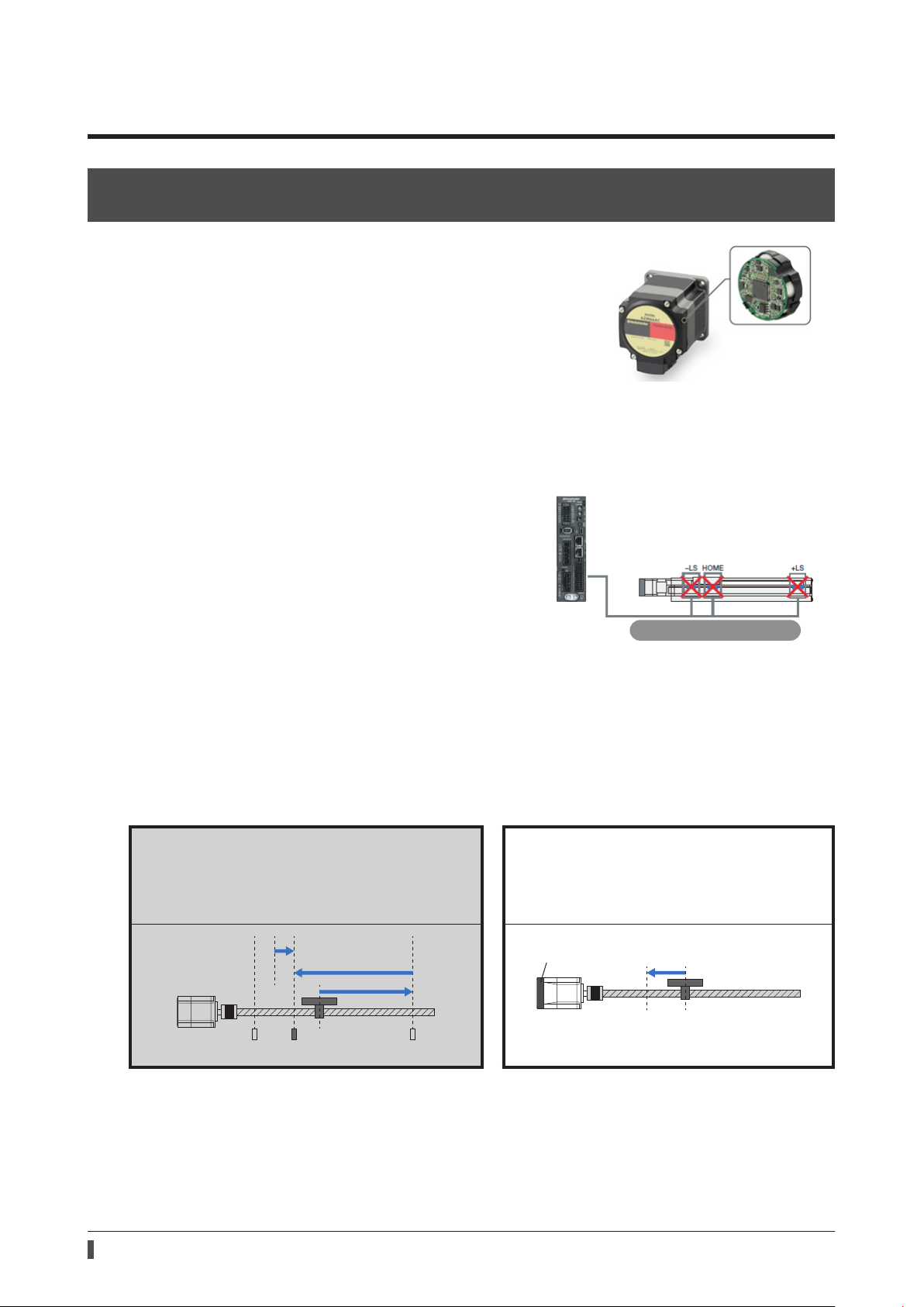
The ABZO sensor is a small-sized low-cost mechanical multirotation absolute sensor that does not require a battery.
It can detect the absolute positions for 1800 revolutions of the
motor shaft from the reference home position, so the position is
never missed.
* The motors of frame size 20 mm (0.79 in.) or 28 mm (1.10 in.) are for 900
revolutions.
No external sensor is required
Return-to-home operation can be executed without using external sensors such as the home position sensor and
limit sensors.
zSaving of wiring
AZ
Series
zCost-cutting for the system
zNot inuenced by malfunction of the sensor
No external sensor is required
Return-to-home time has been shortened
zNo return-to-home operation is required
Since the position information is maintained even if the power is interrupted, positioning operation can be continued
without return-to-home operation after emergency stop or power failure.
zHigh-speed return-to-home
Since the ABZO sensor stores the home position, the motor can return to the home position at a high speed.
Home position detection of traditional position-
control motors
The home position is detected at a low speed by sensing
the limit sensor and the home position sensor.
(2)
(1)
Home position detection of the AZ
Series
The motor directly returns to the home position
stored in the ABZO sensor at a high speed.
(1)
Home position
10
Page 11

No battery is required
No battery is required because the position information is maintained by the ABZO sensor.
zReduction of maintenance frequency
zReplacing a battery is not required
zThe position information is maintained for a long transportation period of equipment
11
Page 12
2 Operations possible with the
Speed
Time
START input
Speed
Time
START input
Push-motion
Speed
Time
START input
Speed
Coordinate
Loop oset
push-motion
Sensor
Speed
AZ
Series
Execute operation by setting the motor operating speed, position (travel amount)
and other items as operation data
Stored data (SD) operation p.55
Positioning operation is performed. Push-motion operation is performed. Continuous operation is performed.
0
Positioning SD
operation
The command position of the rotating mechanism is returned to "0" for
every rotation.
p.66
Positioning push-motion
0
SD operation
p.75
0
Continuous SD
operation
p.78
The position and the speed can be set easily
with the
MEXE02.
Wrap function p.142
Use of sequence function
Linked operations are repeated for the number of times specied.
When you use the loop oset function, you can increase or decrease the travel amount every time the operation is repeated.
Absolute positioning
operation
X-axis
Absolute positioning
operation
Loop function p.93 Loop oset function
Operation is transited by setting an arbitrary I/O signal as a trigger.
The motor can transit to a dierent operation depending on whether or not the trigger signal has been detected.
Torque control
Push-motion
operation
Coordinate
With push-motion
Continuous
operation
Z-axis
Absolute positioning
operation
Event jump function p.95
12
Without
Page 13

Return to the home position
ABZO sensor
HOME
(3)
-
LS +LS
The motor returns to the home position at the speed same
as normal positioning operation without using an external
sensor.
(1)
Home position
stored in the AZ Series
High-speed return-to-home
operation
p.105 Return-to-home operation p.107
The motor returns to the home position by using external
sensors or the stopper on the machine.
(2)
(1)
Perform test operation and operation check
zMacro operation (_p.121)
A specic input signal is turned ON to execute the operation corresponding to the signal.
The operating speed, travel amount, acceleration/deceleration rate are set with parameters.
Start operation at the same time as writing of operation data
(Modbus RTU)
zDirect data operation (_p.302)
You can use this operation to change the setting of operation data frequently, to change the speed and travel amount
according to the load, for example.
When the data of the trigger set to be reected is input by using the touch panel, etc., it is reected to the operation
at the same time as input.
Perform operation by inputting pulses
zPulse-input operation (_p.481)
Operation data are set to the master controller to execute operation. The operation data to be executed are selected
in the master controller.
Pulse input operation cannot be executed with the built-in controller type driver.
13
Page 14
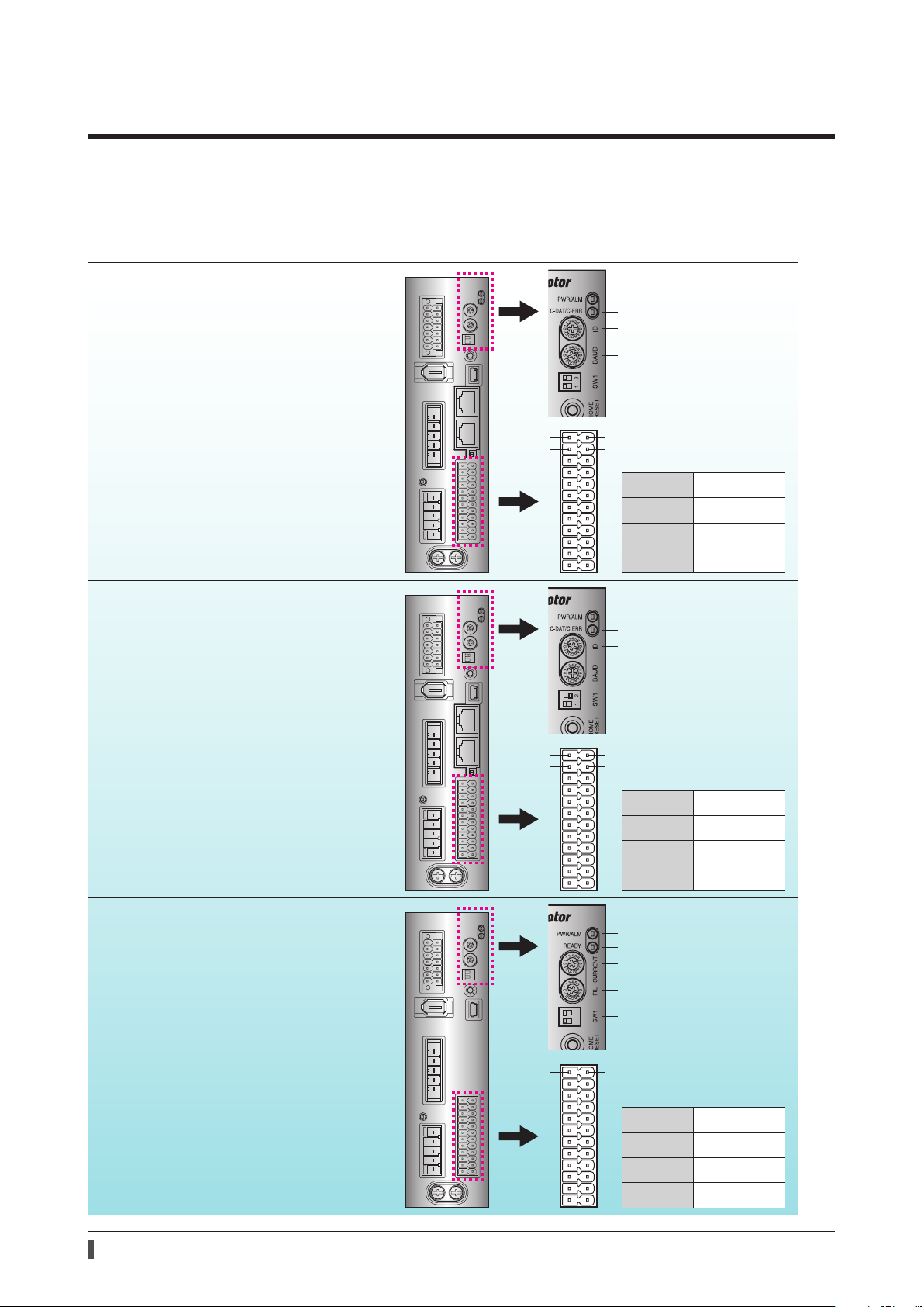
3 Types and overview of driver
There are 3 types of drivers in the AZ Series as shown below. I/O signals, setting items, and LEDs vary depending on
the driver type.
AC power input type
Built-in controller type
Operates via industrial network
Monitors the motor information via a
programmable controller or touchscreen
Operates via RS-485 communication
Operates via I/O control
Pulse input type with RS-485
communication interface
Operates via industrial network
Monitors the motor information via a
programmable controller or touchscreen
Operates via RS-485 communication
Operates via I/O control
Operates by pulse input
PWR/ALM LED
C-DAT/C-ERR LED
Address number
Transmission rate
Function setting switch
Protocol
Address number (extended)
1
2
1
2
13
Pin Nos.1, 2, 13, and 14
14
are for control input
Pin No.1
Pin No.2
Pin No.13
Pin No.14
PWR/ALM LED
C-DAT/C-ERR LED
Address number
Transmission rate
Function setting switch
Protocol
Address number (extended)
13
Pin Nos.1, 2, 13, and 14
14
are for pulse input
Pin No.1
Pin No.2
Pin No.13
Pin No.14
DIN0 [START]
DIN2 [M1]
DIN1 [M0]
DIN3 [M2]
CW+ [PLS+]
CCW+ [DIR+]
CW- [PLS-]
CCW- [DIR-]
Pulse input type
Operates by pulse input
14
PWR/ALM LED
READY LED
Base current rate
Command lter
Function setting switch
Pulse input mode
Resolution
1
2
13
Pin Nos.1, 2, 13, and 14
14
are for pulse input
Pin No.1
Pin No.2
Pin No.13
Pin No.14
CW+ [PLS+]
CCW+ [DIR+]
CW- [PLS-]
CCW- [DIR-]
Page 15
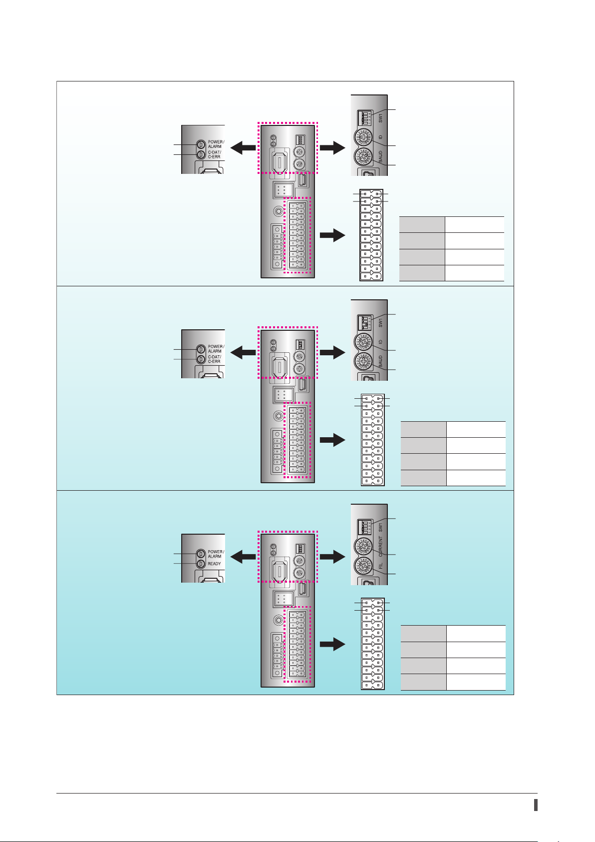
DC power input type
Built-in controller type
POWER/ALARM LED
C-DAT/C-ERR LED
Function setting switch
Protocol
Address number (extended)
Address number
Transmission rate
Operates via industrial network
Monitors the motor information via a
programmable controller or touchscreen
Operates via RS-485 communication
Operates via I/O control
Pulse input type with RS-485
communication interface
POWER/ALARM LED
C-DAT/C-ERR LED
Operates via industrial network
Monitors the motor information via a
programmable controller or touchscreen
Operates via RS-485 communication
Operates via I/O control
Operates by pulse input
1
2
13
Pin Nos.1, 2, 13, and 14
14
are for control input
Pin No.1
Pin No.2
Pin No.13
Pin No.14
DIN0 [START]
DIN2 [M1]
DIN1 [M0]
DIN3 [M2]
Function setting switch
Protocol
Address number (extended)
Address number
Transmission rate
1
2
13
Pin Nos.1, 2, 13, and 14
14
are for pulse input
Pin No.1
Pin No.2
Pin No.13
Pin No.14
CW+ [PLS+]
CCW+ [DIR+]
CW- [PLS-]
CCW- [DIR-]
Pulse input type
POWER/ALARM LED
READY LED
Operates by pulse input
When "PULSE-I/F" is described in this manual or the
When "PULSE-I/F" is described in this manual or the
•Pulse input type with RS-485 communication interface.
•Pulse input type
MEXE02
Function setting switch
Pulse input mode
Resolution
Base current rate
Command lter
1
2
13
Pin Nos.1, 2, 13, and 14
14
are for pulse input
Pin No.1
Pin No.2
Pin No.13
Pin No.14
CW+ [PLS+]
CCW+ [DIR+]
CW- [PLS-]
CCW- [DIR-]
MEXE02
, the contents are applied to the following drivers.
15
Page 16

4 How to use OPERATING MANUALS for
product
OPERATING MANUALS for the AZ Series are listed below.
The OPERATING MANUAL Function Edition (this manual) does not come with the product.
Always keep the manual where it is readily available.
Type and description of OPERATING MANUAL
Read these manuals rst
Series AC Power Input/DC Power Input
AZ
•Motor Edition (supplied with the motor)
•Driver Edition (supplied with the driver)
These manuals explain items from preparation to basic
operations, etc.
This manual explains more detailed operations, functions,
etc. that are not described in OPERATING MANUAL
supplied with the product.
Series AC Power Input/DC Power Input
AZ
•Function Edition (this manual)
•The setting unit may vary depending on the application such as the
Note that when you set the operation data and parameters.
This manual use a setting unit "step" for explanation.
•This manual describes the contents of the driver Ver.4.00 and later.
Note that some functions can not be used in a driver older than Ver.4.00.
You can check the driver version on the unit information monitor of the
Series UL APPENDIX
AZ
•APPENDIX UL Standards for the AZ Series
* Attached to the UL Standard qualied product.
•Before starting operation
•Operation
•I/O signals
•Parameter
•Method of control via Modbus RTU (RS-485
communication)
•Method of control via industrial network
•Address list
•Measures for various cases
•Alarm and information
•Extended setting for pulse input operation
MEXE02.
This appendix includes information required for
certication of the UL Standards.
MEXE02.
(
_
p.442)
16
Page 17

Type and description of OPERATING MANUAL
Motorized actuator
•Actuator Edition (supplied with the actuator)
•Function Setting Edition
The Actuator Edition explains setting methods and
maintenance for actuators.
The Function Setting Edition explains settings of
parameters required for when an actuator is combined
with a driver.
Network Converter
•USER MANUAL
About terms and units
Terms and units to be used vary depending on a motor or motorized actuator. This manual explains by using the
terms of the motor.
When the motorized actuator is used, read this manual by replacing the terms.
Ter m
Unit
Motor Motorized actuator
Torque Thrust force
Moment of inertia Mass
Rotation Movement
CW direction Forward direction
CCW direction Reverse direction
Rotation speed Speed
Resolution Minimum travel amount
N·m N
kHz/s m/s
2
This manual explains functions, installation/connection
methods, operating methods and others about the
network converter.
17
Page 18
5 Expansion of supported contents
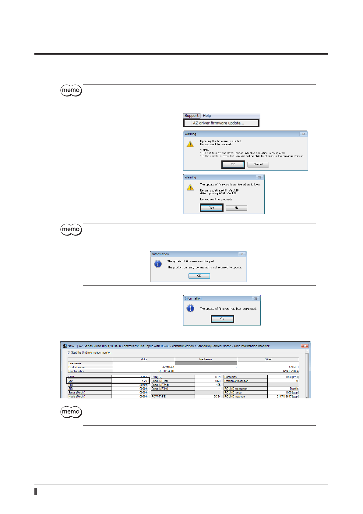
For drivers of the AZ Series, the rmware can be updated using the support software
Download the latest
•Stop the motor before starting the update of rmware.
•Check on the Oriental Motor Website for the latest rmware version.
1. Click on [AZ driver rmware update] from the
[Support] menu.
2. Click [OK].
3. Click [Yes].
Updating the rmware starts.
•Do not turn o the driver power until the update of rmware is completed.
•Once the update of rmware is executed, the version cannot be returned to the previous one.
•If the rmware has already been updated, the following dialog box is shown.
MEXE02
from Oriental Motor Website Download Page.
MEXE02
(ver.3.51 or later).
4. After it is completed, click [OK].
The rmware version can be checked with the unit information monitor.
Even if the rmware is updated, the settings for the operation data and parameters before updating
have been retained.
18
Page 19

1
Before starting operation
This chapter explains contents to be performed before starting
operation.
1 Steps of preparation for operation .........................................................................20
2 Starting the
3 Copying the xed value (parameter) of the ABZO sensor to driver ........... 22
4 Creation of recovery data le and method of recovery .................................. 24
5 Setting of display unit and resolution ................................................................... 29
6 Home position setting ................................................................................................ 36
7 Wrap setting ................................................................................................................... 39
8 Setting of software limit ............................................................................................. 44
9 Operation check ............................................................................................................ 47
10 Backup of data ............................................................................................................... 50
MEXE02
................................................................................................. 21
Page 20

Steps of preparation for operation
1 Steps of preparation for operation
1 Before starting operation
To prepare for operation, use the
Since the procedure is dierent in motors and motorized actuators, perform the preparation for operation according
to the product used.
Motor (standard type/geared type) Motorized actuator
Setting of display unit and resolution
p.29
_
Set the display unit and resolution with the "User unit
setting support wizard" of the
Home position setting
Wrap setting
Set the wrap function as necessary.
_
MEXE02
_
p.39
MEXE02
p.36
.
Starting the
.
MEXE02
Match the xed value of the ABZO sensor with the setting
p.21
_
Copying the xed value (parameter)
of the ABZO sensor to driver _p.22
value of the driver parameter in the
Creation of recovery data le and method of
recovery _p.24
Save the information of the factory setting.
Perform before installing to equipment without fail.
MEXE02
.
Setting of software limit
If a sensor is not used, the setting of the software limit is recommended.
Operation check
Check the set operation with "Teaching, remote operation" of the
Backup of data
Back up the set data.
_
_
_
p.47
p.50
p.44
MEXE02
.
20
Page 21
Starting the MEXE02
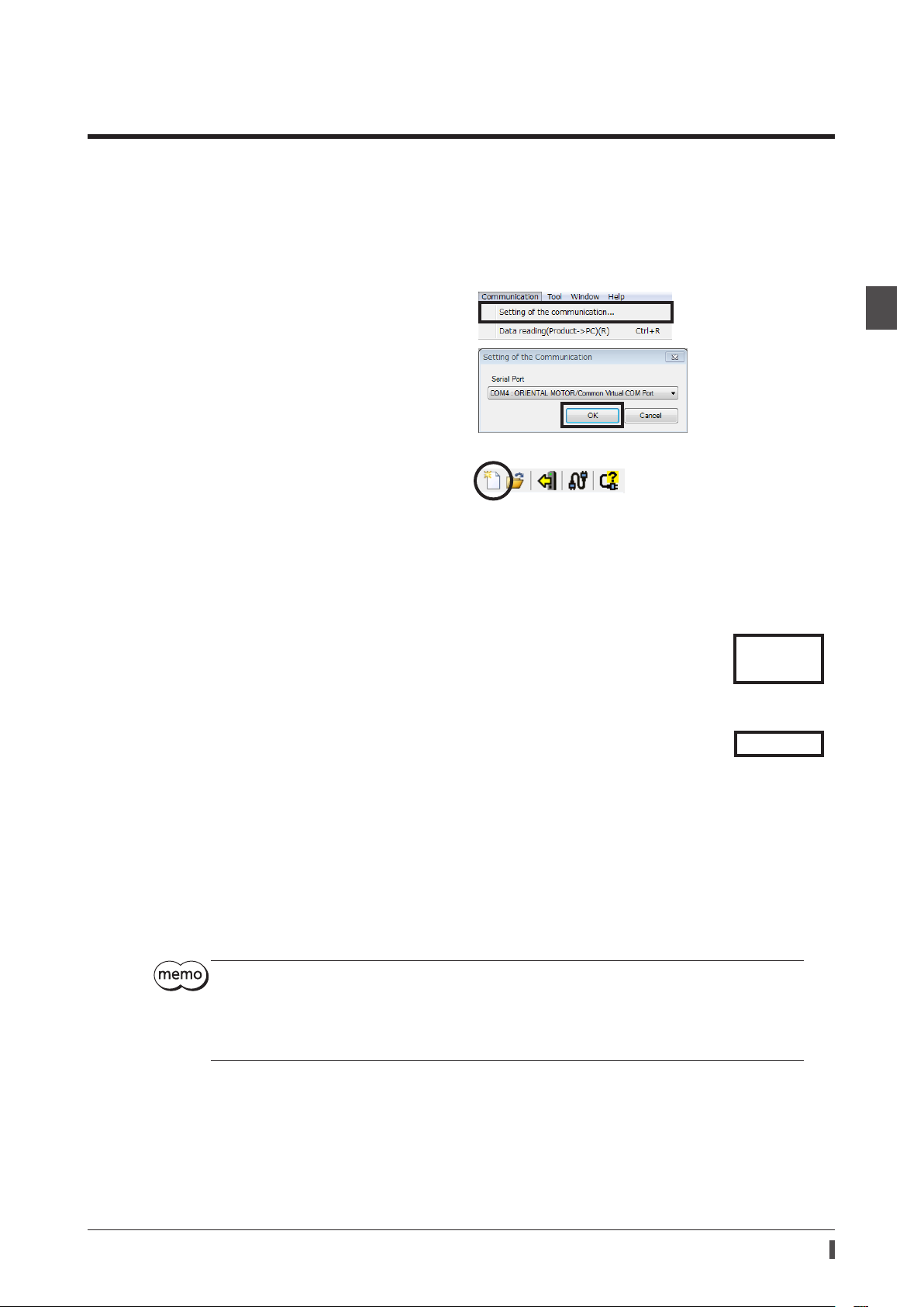
2 Starting the
1. Connect the PC on which the
1) Start the
2) Connect the driver and PC with a USB cable.
3) Turn on the power to the driver.
2. Set the communication port.
1) Click [Setting of the communication] from the
[Communication] menu.
2) Select the "ORIENTAL MOTOR/Common virtual
COM port", and click [OK].
3. Select the product.
1) Click the [New] icon in the toolbar.
2) Click [Search model] on the Select product
window.
MEXE02
.
MEXE02
MEXE02
has been installed and a driver.
1 Before starting operation
3) Check the connected product is selected and
click [OK].
For the pulse input type driver, if No.1 of the function setting switch (SW1) is set to ON (10,000 P/R),
"Resolution 10,000 P/R" is selected in the "Motor/actuator" eld on the "Select product" window. If
"Resolution 10,000 P/R" is selected, the setting by the user unit setting support wizard cannot be
performed. When the resolution is set with the parameter, set the No.1 of the SW1 to OFF. The new
settings of SW1 will become eective after the power is cycled.
After this, the procedure varies based on the product used. Refer to the corresponding page.
Customers who use the standard type and geared type motors _p.29
Customers who use motorized actuators _p.22
21
Page 22
1 Before starting operation
Copying the xed value (parameter) of the ABZO sensor to driver
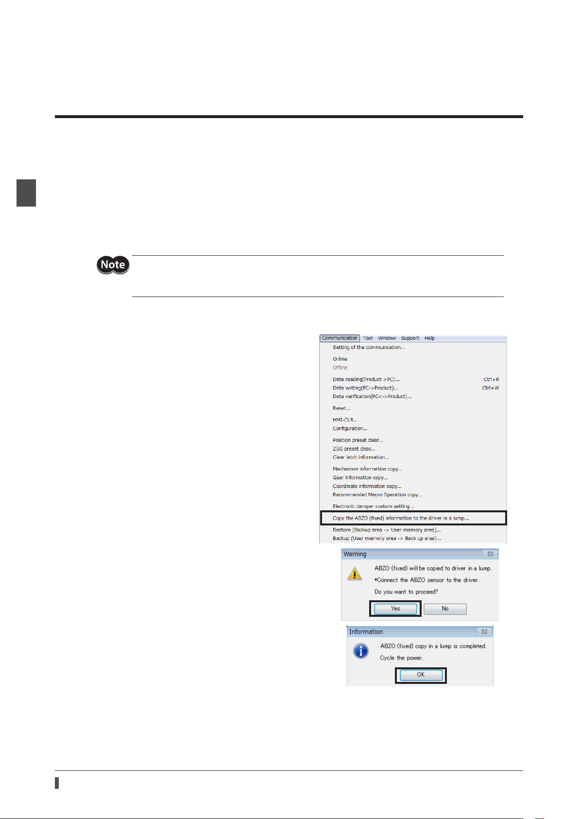
3 Copying the xed value (parameter) of
the ABZO sensor to driver
For parameters of the AZ Series, the dierent values are stored in the ABZO sensor and driver.
The values based on the product specications such as recommended macro operation and position coordinate
information are stored in the ABZO sensor. The values stored in the ABZO sensor cannot be changed because of the
xed value.
Meantime, the values for the standard type (motor only) are stored in the driver parameters.
In a state of the factory shipment, parameters stored in the ABZO sensor are used preferentially. However, if
parameters are changed with the
be changed to the values set in the driver parameters. Therefore, an unexpected movement may cause when an
operation is executed. In order to prevent such troubles, copy the xed value in the ABZO sensor to the driver
parameter, and match the setting value of the driver parameter and the xed value of the ABZO sensor.
After writing the parameter (example: electronic gear, etc.), which was changed to [Manual setting]
and set, from the
parameter that was changed with the manual setting does not return to the xed value.
MEXE02
MEXE02
or other methods, all parameters including the changed parameters will
to the driver, even if the xed value of the ABZO sensor is copied, the
Procedure
1. Click the [Communication] menu of the
select the [Copy the ABZO (xed) information to the
driver in a lump].
2. Click [Yes].
The ABZO information (xed value) is copied in the
driver.
MEXE02
, and
22
3. After it is completed, click [OK].
4. Cycle the driver power.
5. Check whether the copied value is applied on the unit
information monitor window.
Page 23
Copying the xed value (parameter) of the ABZO sensor to driver
zUnit information monitor window
1 Before starting operation
zDescription of each item
Item Description
Active Parameter value presently used is shown.
Driver parameter Parameter value set in the driver using the
ABZO (xed)
The values of parameters stored in the ABZO sensor are shown.
They cannot be changed because of the xed value.
MEXE02
or communication is shown.
23
Page 24

1 Before starting operation
Creation of recovery data le and method of recovery
4 Creation of recovery data le and
method of recovery
4-1 Creating the recovery data le
The recovery data le is a le that information of the factory setting is stored.
At the beginning, create the recovery data le for when the product is replaced with maintenance or the product is
malfunctioned.
Save the recovery data le in a PC as a data le.
•If you are the customer to use a motorized actuator, create the recovery data le without fail.
•Be sure to create the recovery data le before installing the motorized actuator to equipment.
Creating procedure for recovery data le
1. Start the
Check the connected product is selected.
2. Copy the ABZO information (xed value).
1) Click [Copy the ABZO (xed) information
2) Click [Yes].
MEXE02
to the driver in a lump] from the
[Communication] menu.
The ABZO information (xed value) is
copied in the driver.
in the steps of "2 Starting the
MEXE02
" on p.21.
24
3) After it is completed, click [OK].
4) Cycle the driver power.
Page 25
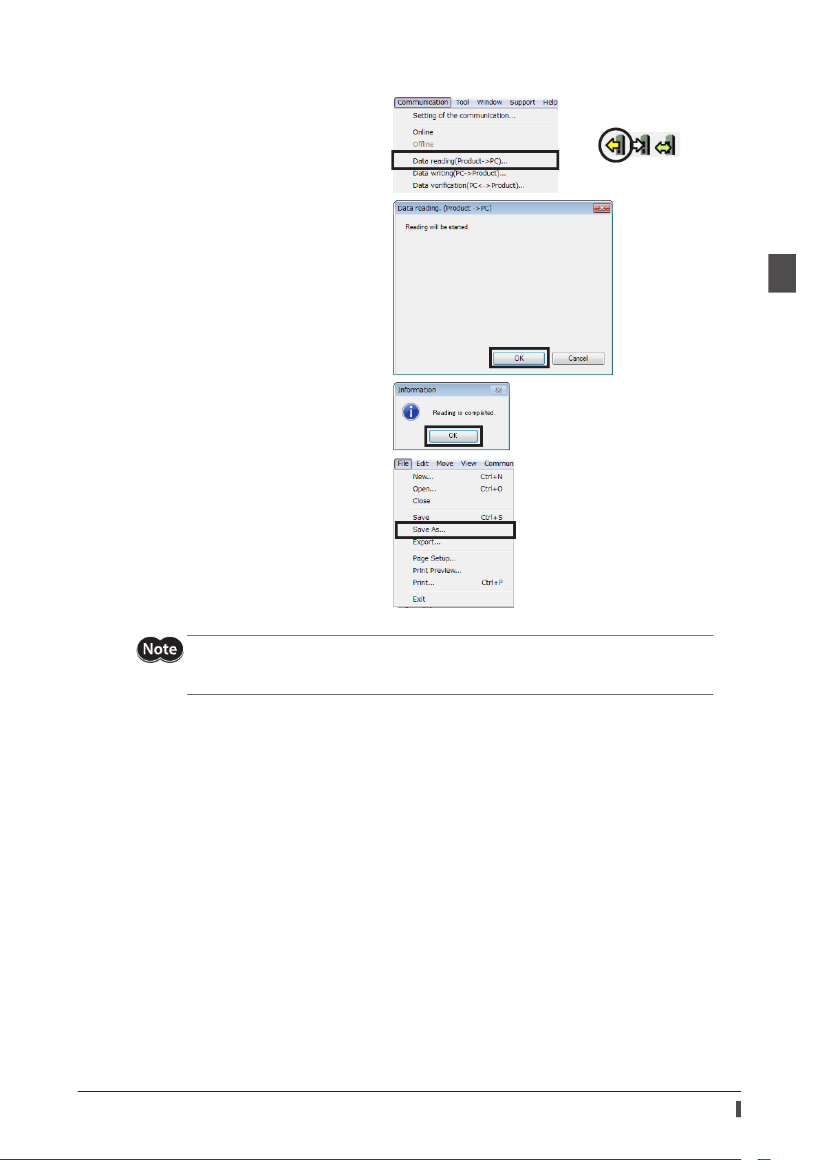
3. Read the ABZO information stored in the driver.
1) Click the [Data reading (Product → PC)]
from the [Communication] menu or click
the [Data reading (Product → PC)] icon in
the toolbar.
2) Click [OK].
Data reading is started.
3) After it is completed, click [OK].
The read data is shown on the screen.
Creation of recovery data le and method of recovery
or
1 Before starting operation
4. Create the recovery data le.
Click [Save as] from the [File] menu.
A desired le name and storage destination
can be used.
The factory setting of the motorized actuator is saved as the recovery data le.
For the recovery, create two les that are the recovery data le stored the factory setting and the nal
backup le (
have been created in advance, the equipment can be restored smoothly.
p.50) applied the operation data and others. If the recovery data le and backup le
_
25
Page 26
1 Before starting operation
Creation of recovery data le and method of recovery
4-2 Method of recovery
The recovery can be performed under the precondition of having created the recovery data le according to the "4-1
Creating the recovery data le" on p.24.
When the motor or driver was replaced, be sure to perform the recovery and the home
position resetting. Unless the recovery and the home position resetting are performed, the
followings may happen.
•The moving part may cause unexpected operations, resulting in injury or damage to
equipment.
•The moving part of the motorized linear slide or motorized cylinder may collide with the
mechanical stopper.
•A load may collide with other equipment.
•If "Search model" is performed with the
identied as the AZ Series "Standard/geared motor."
•Refer to the OPERATING MANUAL Actuator Edition for how to replace the motor.
MEXE02
after the motor is replaced, the product is
When the motor and driver were malfunctioned
1. Replace the motor and driver, and turn on the power.
2. Open the recovery data le in the
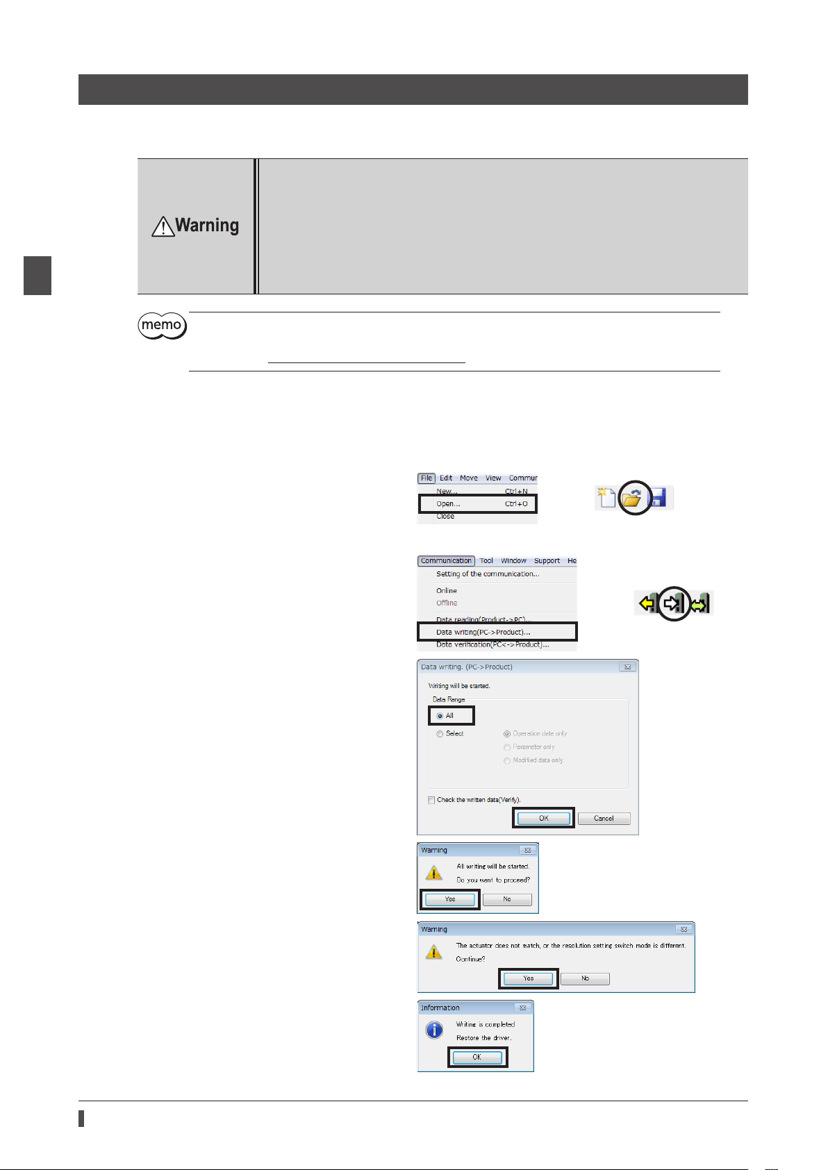
1) Click the [Open] from the [File] menu or click
the [Open] icon in the toolbar.
Select the recovery data le, and click [Open].
3. Check the data is correct, and write to the driver in the following steps.
1) Click the [Data writing (PC → product)] from
the [Communication] menu or click the [Data
writing (PC → product)] icon in the toolbar.
2) Select the [All], and click [OK].
MEXE02
.
or
or
26
3) Click [Yes].
Writing data is started.
If the following message appears, click [Yes].
4) After it is completed, click [OK].
5) Cycle the driver power.
Page 27
Creation of recovery data le and method of recovery
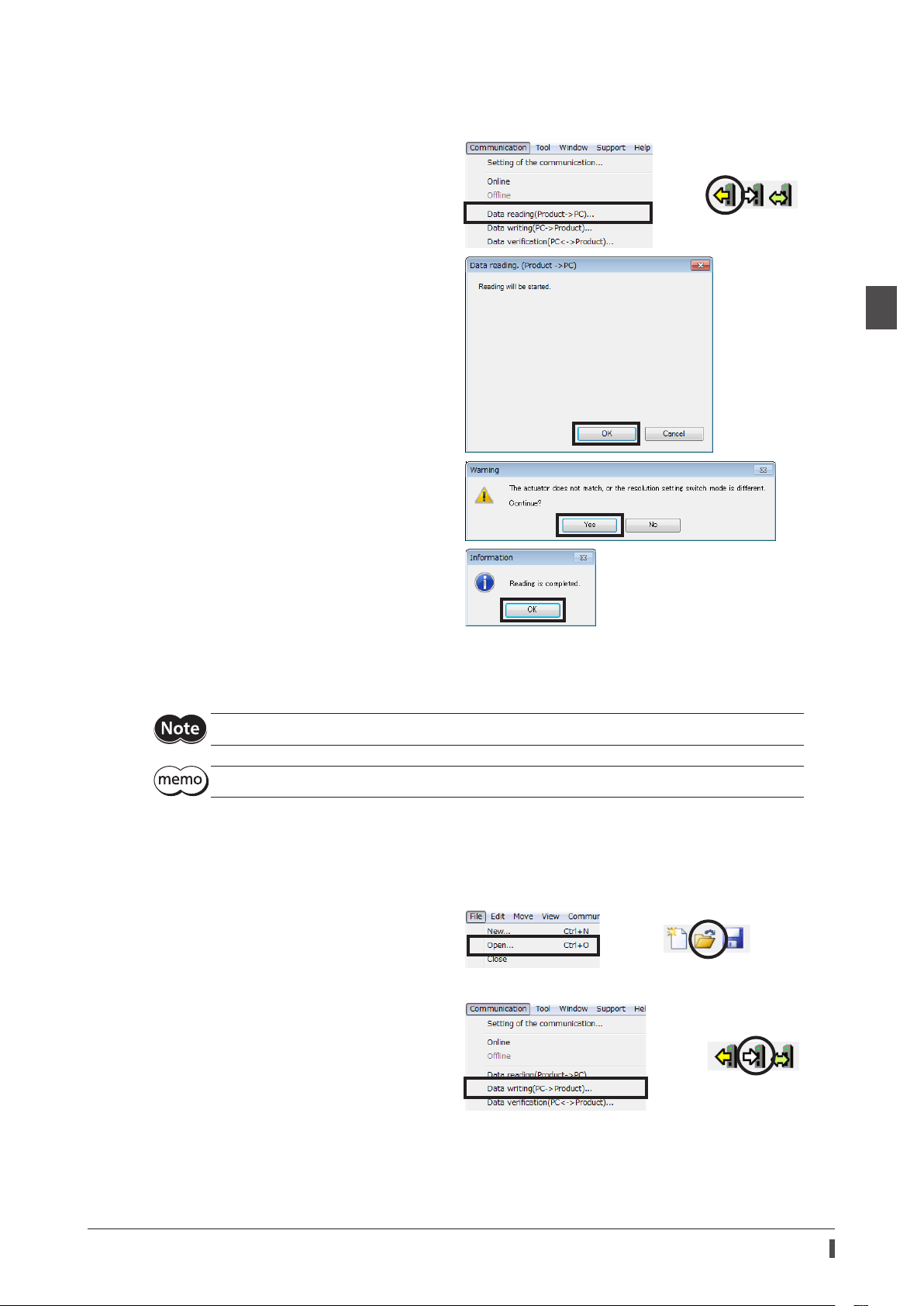
4. Read the information of the factory setting written to the driver.
When the motor is replaced, set the home position again after reading the driver information.
The communication function of the
1) Click the [Data reading (product → PC)] from
the [Communication] menu or click the [Data
reading (product → PC)] icon in the toolbar.
2) Click [OK].
Data reading is started.
If the following message appears, click [Yes].
MEXE02
cannot be used without reading the driver information.
or
1 Before starting operation
3) After it is completed, click [OK].
The read data is shown on the screen.
All data and parameters in the driver including the ABZO information were read in the
5. Refer to p.36 and set the home position again.
6. Refer to p.24 and create the recovery data le for the product after replacement.
Save the read driver information as the new recovery data le.
The details of the written parameters can be checked with the "unit information monitor."
When the driver was malfunctioned
1. Replace the driver, and turn on the power.
2. Open the recovery data le in the
1) Click the [Open] from the [File] menu or click
the [Open] icon in the toolbar.
Select the recovery data le, and click [Open].
3. Check the data is correct, and write to the driver in the following steps.
1) Click the [Data writing (PC → product)] from
the [Communication] menu or click the [Data
writing (PC → product)] icon in the toolbar.
MEXE02
.
or
MEXE02
or
.
27
Page 28
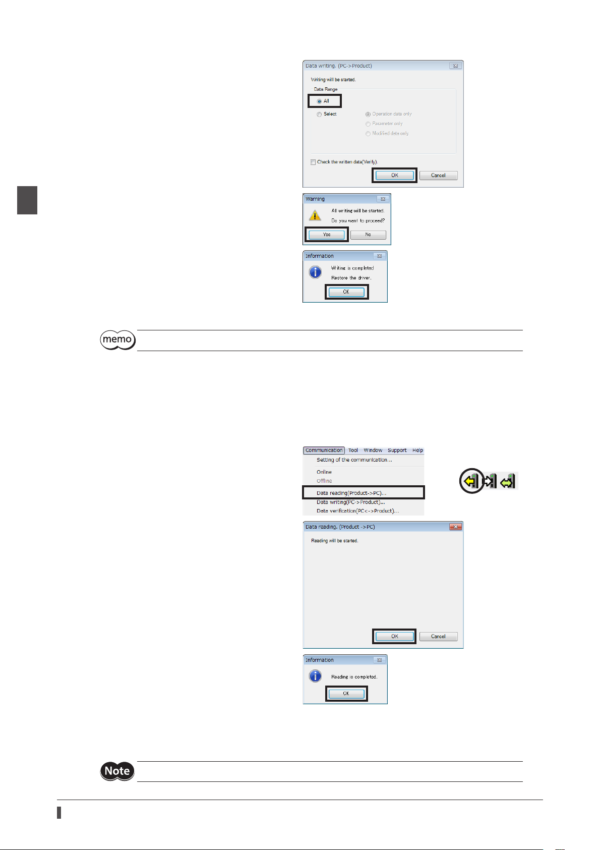
1 Before starting operation
Creation of recovery data le and method of recovery
2) Select the [All], and click [OK].
3) Click [Yes].
Writing data is started.
4) Click [OK].
5) Cycle the driver power.
The details of the written parameters can be checked with the "unit information monitor."
When the motor was malfunctioned
1. Replace the motor, and turn on the power.
2. Read the driver information to the PC.
When the motor is replaced, set the home position again after reading the driver information.
The communication function of the
1) Click the [Data reading (product → PC)] from
the [Communication] menu or click the [Data
reading (product → PC)] icon in the toolbar.
2) Click [OK].
MEXE02
cannot be used without reading the driver information.
or
28
3) After it is completed, click [OK].
The read data is shown on the screen.
All data and parameters in the driver including the ABZO information were read in the
3. Refer to p.36 and set the home position again.
4. Refer to p.24 and create the recovery data le for the product after replacement.
Save the read driver information as the new recovery data le.
MEXE02
.
Page 29

Setting of display unit and resolution
5 Setting of display unit and resolution
The display unit and resolution can be set using the "User unit setting support wizard" of the
amount, speed and others can be displayed or input by a desired unit.
5-1 Setting example for when an index table is used
1. The display unit and resolution can be set using the "User unit setting support wizard."
1) Click [System of units customize wizard].
The window of the user unit setting
support wizard is shown.
2) Click [Next].
3) Select the mechanism used.
Select the [Table mechanism], and click
[Next].
MEXE02
. The travel
1 Before starting operation
4) Set the mechanism information.
When the "table" is selected, the setting of
the mechanism information is not
required. Click [Next].
29
Page 30
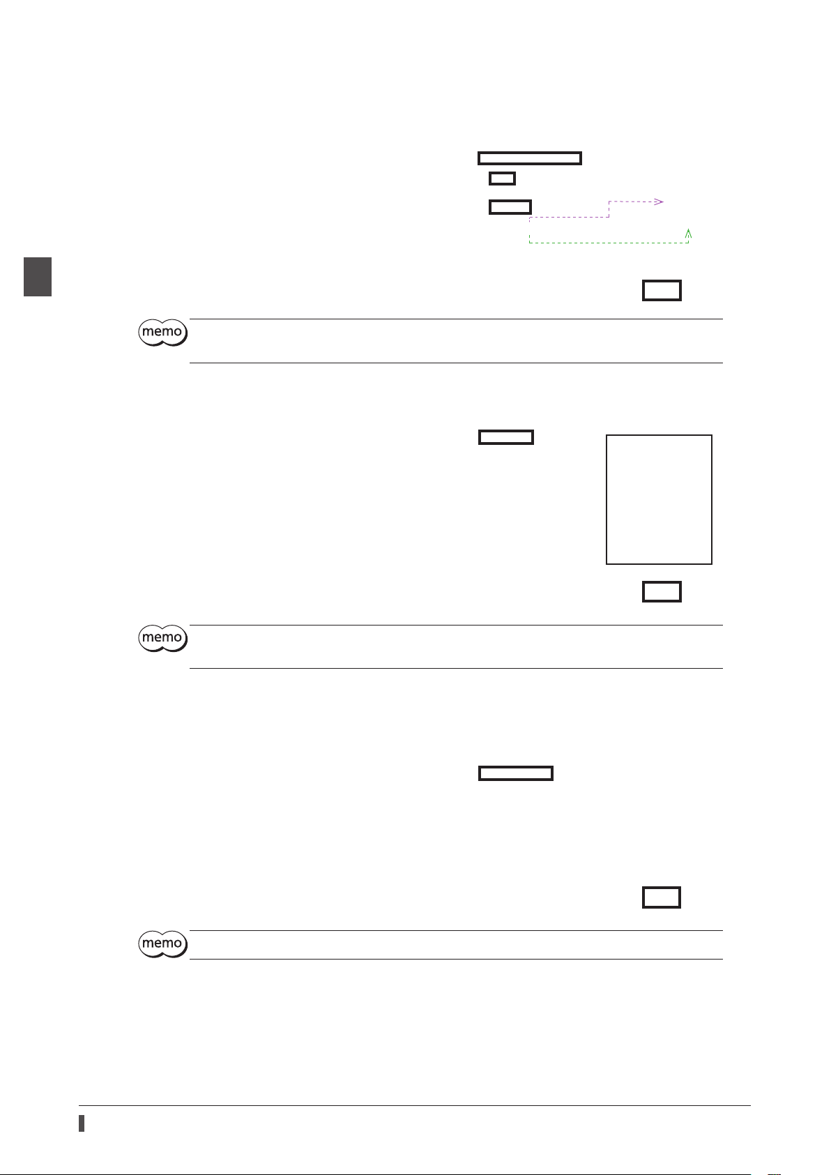
1 Before starting operation
Setting of display unit and resolution
5) Set the speed reduction ratio of the gears.
This is an example for when the geared
motor of the gear ratio 10 is used.
Set as shown in the gure, and click [Next].
When gears or pulleys are not used externally, select "Use the factory default settings of selected
product," and click [Next].
6) Set the minimum step angle of the table.
This example is set as "0.01°." Input "0.01",
and click [Next].
*1 The set contents are shown.
Since the wrong setting is indicated in
red color, set it again.
*2 If there is a wrong setting, the wrong
content and remedial actions are
indicated.
*1
When the wrap function (_ p.39) is used, set so that the resolution per revolution of the motor output
shaft is an integral number.
7) Set the display unit.
Select "deg" here, and click [Next].
The unit for when operating via network is "step."
*2
30
Page 31

Setting of display unit and resolution
8) Set the acceleration/deceleration unit.
Select "s" here, and click [Finish].
If "s" is selected in the acceleration/deceleration unit, the initial value of the "Starting/changing rate"
and "Stopping deceleration" is "1000 s." After the setting was complete, change the value according
to the operating condition.
2. Since the parameters set in the driver is prioritized, set the mechanism settings parameter to "Manual setting."
1) Click “Motor and mechanism (coordinates/
JOG/home operation)” under “Parameter”
in the tree view.
The motor and mechanism parameter is
shown.
1 Before starting operation
2) Change the "Mechanism settings"
parameter to "Manual setting."
3. Write the parameters to the driver.
1) Click the [Data writing (PC → product)]
from the [Communication] menu or click
the [Data writing (PC → product)] icon in
the toolbar.
2) Select "All" in the data range, and click
[OK].
or
3) Click [OK].
Writing parameters is started.
31
Page 32

1 Before starting operation
Setting of display unit and resolution
4) Click [OK].
4. Cycle the driver power.
Parameters are applied.
5-2 Setting example for when a linear mechanism is assembled
1. The display unit and resolution can be set using the "User unit setting support wizard."
1) Click [System of units customize wizard].
The window of the user unit setting
support wizard is shown.
2) Click [Next].
3) Select the mechanism used.
Select the [Linear motion mechanism],
and click [Next].
4) Set the travel amount per a revolution.
This example is set as "1 mm." Input "1,"
and click [Next].
32
Page 33

5) Set the speed reduction ratio of the gears.
The factory setting is used here.
Select "Use the factory default settings of
selected product," and click [Next].
6) Set the minimum step angle of the table.
This example is set as "0.0005 mm." Input
"0.0005", and click [Next].
*1 The set contents are shown.
Since the wrong setting is indicated in
red color, set it again.
*2 If there is a wrong setting, the wrong
content and remedial actions are
indicated.
Setting of display unit and resolution
1 Before starting operation
*1
When the wrap function (_ p.39) is used, set so that the resolution per revolution of the motor output
shaft is an integral number.
7) Set the display unit.
Select "mm" here, and click [Next].
The unit for when operating via network is "step."
*2
33
Page 34

1 Before starting operation
Setting of display unit and resolution
8) Set the acceleration/deceleration unit.
Select "s" here, and click [Finish].
If "s" is selected in the acceleration/deceleration unit, the initial value of the "Starting/changing rate"
and "Stopping deceleration" is "1000 s." After the setting was complete, change the value according
to the operating condition.
2. Since the parameters set in the driver is prioritized, set the mechanism settings parameter to "Manual setting."
1) Click “Motor and mechanism (coordinates/
JOG/home operation)” under “Parameter”
in the tree view.
The motor and mechanism parameter is
shown.
2) Change the "Mechanism settings"
parameter to "Manual setting."
3. Write the parameters to the driver.
1) Click the [Data writing (PC → product)]
from the [Communication] menu or click
the [Data writing (PC → product)] icon in
the toolbar.
2) Select "All" in the data range, and click
[OK].
or
34
3) Click [Yes].
Writing parameters is started.
Page 35

4) Click [OK].
4. Cycle the driver power.
Parameters are applied.
Setting of display unit and resolution
1 Before starting operation
35
Page 36

1 Before starting operation
Home position setting
6 Home position setting
The home position has not set at the time of shipment. Before starting an operation, be sure to set the home position.
Perform the home position setting only once initially. Once the home position is set, the driver keeps the home
information even if the power supply is shut down.
•Refer to the OPERATING MANUAL Driver for how to set the home position with the HOME PRESET
switch.
•The home position is written to the non-volatile memory. The non-volatile memory can be
rewritten approximately 100,000 times.
When a sensor is not used in return-to-home operation
1. Click the [Teaching, remote operation] shortcut
button or click the [Teaching, remote operation]
icon in the toolbar.
2. Click "Start the teaching remote operation."
or
3. Operate the motor till the home position using
the JOG operation buttons.
Adjust the position while checking the
"Command position (CPOS)" in the "Driver
status" eld.
* Use the FREE operation buttons to adjust
the home position manually.
If the [FREE: ON] is clicked, the motor
becomes a non-excitation state, and the
motor output shaft can be rotated by an
external force.
JOG operation buttons
*
36
Page 37

Descriptions of JOG operation buttons
HOMESRV-LS FW-LS
Home position setting
Button
Assigned input signal
name
RV-JOG-H
RV-JOG
RV-JOG-P
STOP This is used to stop the motor immediately.
FW-JOG-P
FW-JOG
FW-JOG-H
If the JOG travel amount is changed, the "(HOME) Operating current for push motion homeseeking
[%]" parameter is automatically changed to 100%. When the JOG travel amount is changed, set the
"(HOME) Operating current for push motion homeseeking [%]" parameter to 70% or less.
When the operating condition is changed, set the "JOG/HOME/ZHOME operation setting" to "Manual
setting."
This is used to perform continuous operation at the operating speed set
in the "(JOG) Operating speed (high)" parameter
This is used to perform continuous operation at the operating speed set
in the "(JOG) Operating speed" parameter
This is used to perform positioning operation in the travel amount set in
the "minimum travel amount" of the JOG operation buttons.
This is used to perform positioning operation in the travel amount set in
the "minimum travel amount" of the JOG operation buttons.
This is used to perform continuous operation at the operating speed set
in the "(JOG) Operating speed" parameter
This is used to perform continuous operation at the operating speed set
in the "(JOG) Operating speed (high)" parameter
Relationship between the input signal and parameter
1 Before starting operation
4. Click [Position preset].
The home position is set.
When a sensor input is used in return-to-home operation
Input signals, which are used in return-to-home operation, are assigned with the
according to external sensors used. This represents an example for when return-to-home operation is executed in the
3-sensor mode.
MEXE02
Input signals required in return-to-home operation
Input signal
name
HOMES Home sensor
FW-LS Limit sensors (+)
RV-LS Limit sensors (−)
HOME Signal to start return-to-home operation.
Description
. Assign the input signals
37
Page 38

Home position setting
zBuilt-in controller type
Input signals (HOMES, FW-LS, RV-LS) from sensors and signals (M0, M1, START, STOP) related in positioning operation
are assigned to direct I/O. And the alarm reset signal (ALM-RST) is remained.
The HOME is assigned to both direct I/O and remote I/O so that return-to-home operation can be performed even in
both of them.
Assignment example of direct I/O
Assignment example of remote I/O
1 Before starting operation
*
*
*
* In the case of 2-sensor mode, assign the "M2" or "ZHOME."
* In the case of 2-sensor mode, assign the "ZHOME."
•Assign the input signals according to external sensors used.
•When return-to-home operation is performed using remote I/O, assign the sensor input to direct
I/O.
zPulse input type with RS-485 communication interface, pulse input type
Input signals (HOMES, FW-LS, RV-LS) from sensors and the alarm reset signal (ALM-RST) are assigned. And the HOME
is assigned so that return-to-home operation can be performed.
* In the case of 2-sensor mode, assign the "ZHOME," "PLS-DIS," or others.
•Assign the input signals according to external sensors used.
•In the case of the pulse input type witn RS-485 communication interface and pulse input type, the
DIN0 to DIN3 are exclusively used for pulse input. Since other signals cannot be assigned, set to
"Not used."
*
*
38
Page 39

7 Wrap setting
The wrap function is a function to automatically preset the position information of the present position when the
number of revolutions of the motor output shaft exceeds the set range. Setting of wrap oset allows you to limit the
operation area of the equipment and control the index table with coordinates on the positive and negative sides.
(
p.42)
_
When the wrap function is not used
zSetting the wrap function
Disable the "Wrap setting" parameter. (Initial value: Eective)
1. Click “Motor and mechanism (coordinates/
JOG/home operation)” under “Parameter” in
the tree view.
The motor and mechanism parameter is
shown.
Wrap setting
1 Before starting operation
2. Set the "Initial coordinate generation/wrap
coordinate setting" parameter to "Manual
setting."
3. Set the "Wrap setting" parameter to
"Disable."
When the wrap function is used
zSetting example: When the motor output shaft rotates 18 revolutions, the index table rotates one
revolution.
Set the parameters in the following steps.
Setting the wrap function
Setting the wrap range
Setting the oset ratio of the wrap range
Setting the oset amount of the wrap range
Writing the set parameters to the driver
39
Page 40

Wrap setting
Related parameters
1 Before starting operation
MEXE02
Motor and mechanism
tree view Parameter name Description
Wrap setting
Initial coordinate
generation & wrap
setting range
Initial coordinate
generation & wrap
range oset ratio
Initial coordinate
generation & wrap
range oset value
STEP 1 Set the wrap function
Set the "Wrap setting" parameter.
1. Click “Motor and mechanism (coordinates/
JOG/home operation)” under “Parameter” in
the tree view.
The motor and mechanism parameter is
shown.
Set the wrap function.
Setting range
0: Disable
1: Enable
Set the wrap range. The position information of
the present position is automatically preset when
the motor has rotated for the number of times set
here.
Setting range
Refer to the next table.
Set the oset ratio of the wrap range.
Setting range
0 to 10,000 (1=0.01%)
Set the amount of oset of the wrap range.
Setting range
−536,870,912 to 536,870,911 steps
Initial
value
1
10
5,000
0
2. Set the "Wrap setting" parameter to
"Eective."
STEP 2 Set the wrap range
Set the "Initial coordinate generation & wrap setting range" parameter. When the motor rotates the number of
revolutions that was set, the position information of the present position is automatically preset. Set when
unidirectional operation or proximity operation is performed using a rotating mechanism.
1. Click “Motor and mechanism (coordinates/
JOG/home operation)” under “Parameter” in
the tree view.
The motor and mechanism parameter is
shown.
40
Page 41

2. Set the "Initial coordinate generation & wrap
C
1,800 *
C
Electronic gear A
The motors of frame size 20 (0.79 in.) and 28 (1.10 in.) are 900.
C
1,800
1,800
C
1
× 1,000 = 100,000
setting range" parameter.
The internal coordinate of the ABZO sensor
is 900 rev or 1,800 rev.
This example is set to "18" so that the
position information is preset when the
motor output shaft rotates 18 revolutions.
Internal coordinate of the ABZO sensor
Wrap setting
Frame size [mm (in.)]
20 (0.79 in.), 28 (1.10 in.) 900 rev ±450 rev (oset ratio 50%)
40 (1.57 in.), 42 (1.65 in.),
60 (2.36 in.), 85 (3.35 in.),
90 (3.54 in.)
Select a value from the table below, and set in the "Initial coordinate generation & wrap setting
range" parameter.
Internal coordinate of the
ABZO sensor
1,800 rev ±900 rev (oset ratio 50%)
Initial value
Value that can be set in the "Initial coordinate generation & wrap setting range" parameter
In the table below, the values which are surrounded with thick box border cannot be set in 900 rev.
Wrap setting range [rev]
0.5 1.8 4.8 12.0 25.0 72.0 200.0
0.6 2.0 5.0 12.5 30.0 75.0 225.0
0.8 2.4 6.0 14.4 36.0 90.0 300.0
0.9 2.5 7.2 15.0 37.5 100.0 360.0
1.0 3.0 7.5 18.0 40.0 112.5 450.0
1.2 3.6 8.0 20.0 45.0 120.0 600.0
1.5 4.0 9.0 22.5 50.0 150.0 900.0
1.6 4.5 10.0 24.0 60.0 180.0 1,800.0
1 Before starting operation
Setting condition of the "Initial coordinate generation & wrap setting range" parameter
When the wrap range meets the following condition, continuous rotation in the same direction becomes possible
with the home position maintained.
ondition (1)
ondition (2)
Wrap setting range
Wrap setting range × Resolution = Wrap setting range ×× 1,000 = An integer
= An integer
*
Electronic gear B
zSetting example 1
•Internal coordinate of the ABZO sensor: 1,800 rev
•Wrap setting range: 100 rev
•Resolution: 1,000 P/R (Electronic gear A=1, Electronic gear B=1)
•Motor: Standard motor (gear ratio 1)
ondition (1)
ondition (2)
Both Condition (1) and (2) are integers and this meets the setting condition. Wrap is possible.
Wrap setting range
Wrap setting range ×× 1,000 = 100 ×
== 18
100
Electronic gear B
Electronic gear A
1
41
Page 42

Wrap setting
C
1,800
1,800
C
3
×× 1,000 = 4,800
4.5
0
-
9
-
zSetting example 2
•Internal coordinate of the ABZO sensor: 1,800 rev
•Wrap setting range: 14.4 rev
•Resolution: 333.333··· P/R (Electronic gear A=1, Electronic gear B=1)
•Motor: TH geared motor (gear ratio 3.6)
1 Before starting operation
ondition (1)
ondition (2)
Both Condition (1) and (2) are integers and this meets the setting condition. Wrap is possible.
Wrap setting range
Wrap setting range
== 125
14.4
Electronic gear B
Electronic gear A
STEP 3 Set the oset ratio of the wrap range
Set the "Initial coordinate generation & wrap range oset ratio" parameter. The wrap range can be oset in the
negative direction by the set ratio.
1. Click “Motor and mechanism (coordinates/
JOG/home operation)” under “Parameter” in
the tree view.
The motor and mechanism parameter is
shown.
2. Set the "Initial coordinate generation & wrap
range oset ratio" parameter.
Here, 18 revolutions is divided into 50% each
in positive side and negative side so that the
index table can be rotated in both directions.
× 1,000 = 14.4 ×
1
When the "wrap setting range" is 18 rev and the wrap oset ratio is 50%
-
9
4.5 94.5
If the "Wrap setting" parameter or "Initial coordinate generation & wrap setting range" parameter is
changed, the absolute position may be moved. When the parameter is changed, perform high-speed
return-to-home operation or return-to-home operation.
0
-
4.5
42
Page 43

STEP 4 Set the amount of oset of the wrap range
After setting the oset ratio of the wrap range, use when adjusting the home position in increments of a step.
1. Click “Motor and mechanism (coordinates/
JOG/home operation)” under “Parameter” in
the tree view.
The motor and mechanism parameter is
shown.
2. Set the "Initial coordinate generation & wrap
range oset value" parameter.
Set "0" if the setting is not required.
STEP 5 Write the set parameters to the driver
Wrap setting
1 Before starting operation
1. Click the [Data writing (PC → product)] from
the [Communication] menu or click the [Data
writing (PC → product)] icon in the toolbar.
2. Select "All" in the data range, and click [OK].
3. Click [Yes].
Writing parameters is started.
4. Click [OK].
or
5. Cycle the driver power.
Parameters are applied.
If information or alarm of the wrap setting error is generated, the wrap setting condition may not be
satised. Review the setting of the "User unit setting support wizard" or parameters.
43
Page 44

1 Before starting operation
-
10,000
e
10,000
Setting of software limit
8 Setting of software limit
When no sensor is used, the setting of the software limit is recommended.
Set the software limits of the positive and negative sides as well as the stopping method for when the software limit is
detected.
Setting the motor stopping method
Set the stopping method for when the motor reached the software limit.
1. Click the “Base settings” under
“Parameter” in the tree view.
The base setting parameters are
shown.
2. Set the motor stopping method
in the "Software overtravel"
parameter.
When the "Deceleration stop" is selected, take account the distance till the motor stops after starting
deceleration. If the load may contact with the mechanism during deceleration, change the setting to
"Immediate stop" or shorten the brake deceleration in the operation data.
Setting of software limit
Set the software limits in the positive side (forward direction) and negative side (reverse direction).
The set values are saved in the non-volatile memory. The non-volatile memory can be rewritten
approximately 100,000 times.
1. Click the [Teaching, remote operation] shortcut
button or click the [Teaching, remote operation]
icon in the toolbar.
2. Click "Start the teaching remote operation."
3. Set the software limits of the positive and negative
sides in the following steps.
This explains as an example for when the moving
range is set as shown in the gure.
Negative side
or
Positive sid
44
Page 45

1) Using the JOG operation buttons, operate the
motor to the moving range 10,000 of the positive
side.
Adjust the position while checking the "Command
position (CPOS)" in the "Driver status" eld.
Setting of software limit
JOG operation buttons
2) Click the [Preset (CPOS+1)] button in the "Positive
software limit" eld.
1 Before starting operation
3) Click [Yes].
The value that was added 1 to the present
command position is set in the software limit.
4) Operate the motor to the moving range −10,000
of the negative side using the same method as 1).
45
Page 46

1 Before starting operation
Setting of software limit
5) Click the [Preset (CPOS−1)] button in the
"Negative software limit" eld.
6) Click [Yes].
The value that was added −1 to the present
command position is set in the software limit.
46
Page 47

9 Operation check
Perform an operation check for the items set before this section.
Before operating the motor, check the condition of the surrounding area to ensure safety.
Steps for checking
Operation check for return-to-home operation _ p.47
Operation check
1 Before starting operation
Operation check for software limit
_
p.48
STEP 1 Check the operating status of return-to-home operation
When no sensor is used
1. Click the [Teaching, remote operation] shortcut
button or click the [Teaching, remote operation]
icon in the toolbar.
2. Click "Start the teaching remote operation."
3. Execute the following high-speed return-to-home operation, and check the command position (CPOS) is being
"0."
1) Click "ZHOME operation."
or
2) Click [Yes].
High-speed return-to-home operation is started.
3) After the motor stopped, check the command
position (CPOS) is being "0."
If information of ZHOME start error is generated, check the setting of the home position. (_p.36)
47
Page 48

1 Before starting operation
Operation check
When sensors are used
1. Click the [Teaching, remote operation] shortcut
2. Click "Start the teaching remote operation."
3. Execute the following return-to-home operation, and check the command position (CPOS) is being "0."
1) Click "Home operation."
2) Click [Yes].
3) After the motor stopped, check the command
button or click the [Teaching, remote operation]
icon in the toolbar.
Return-to-home operation is started.
position (CPOS) is being "0."
or
When return-to-home operation is executed using the input signal, turn the HOME ON.
STEP 2 Check the operation of the software limit
Operate till the software limit with JOG operation, and check an alarm is generated.
Setting of related parameters
Set the parameters related in JOG operation so that the load may not contact with the mechanism when JOG
operation is performed.
MEXE02
Motor and mechanism
tree view Parameter name Key point for setting
JOG/HOME/ZHOME operation
setting
JOG/HOME/ZHOME operating
current
(JOG) Acceleration/deceleration
rate
(JOG) Operating speed
(JOG) Operating speed (high)
Base settings Software overtravel The stopping method set in p.44 is applied.
If the related parameter is changed, set to "Manual
setting."
If you want to suppress the torque, set the lower
current.
The acceleration/deceleration time and rotation
amount vary depending on the setting unit. Set
according to the unit.
Set according to the equipment you have used.(JOG) Starting speed
48
Page 49

Operation check
1. Click the [Teaching, remote operation] shortcut
button or click the [Teaching, remote operation]
icon in the toolbar.
2. Click "Start the teaching remote operation."
3. Operate the motor using the JOG operation buttons.
Operation check
or
JOG operation buttons
4. If the set software limit is detected, an alarm is
generated.
"67: Software overtravel" is shown on the "Alarm
condition" in the "Driver status" eld.
5. Click the [Alarm reset] button to release the alarm
status.
After releasing the alarm, escape from the software
limit using the [ZHOME operation] button or JOG
operation buttons.
1 Before starting operation
49
Page 50

Backup of data
10 Backup of data
1 Before starting operation
There are the following two methods to backup the contents set in the
MEXE02
zCreate to save the data le
The data edited in the
Data les can be saved in the
Data les saved in the
saved in the CSV format can be edited in applications other than the
MEXE02
MEXE02
or the data read from the driver can be saved as a le.
MEXE02
format and
format (.mx2),
MEXE02
MEXE02
extended format cannot be opened in other applications. Data
extended format (.mx2a), or CSV format (.csv).
MEXE02
zSave in the backup area of the driver
The data opened in the
The data stored by the backup function can be read using the restore function.
Refer to p.441 for details.
MEXE02
can be saved in the backup area of the driver.
.
.
50
Page 51

2
Operation
This part explains the operation functions and parameters.
1 Flow of setting required for positioning operation ......................................... 52
2 Setting of resolution .................................................................................................... 53
3 Stored data (SD) operation .......................................................................................55
4 Return-to-home operation .....................................................................................105
5 Macro operation .........................................................................................................121
6 Relationship between operation type and
operation data and parameter ..............................................................................136
7 Position coordinate management ........................................................................140
Page 52

Flow of setting required for positioning operation
A
p
k
i
•
d
•
operation, etc., the motor is operated
1 Flow of setting required for positioning
operation
2 Operation
OPERATING
MANUAL
Driver
Part Three
Part Four
Part Nine
The contents of are explained in this manual.
• Install the motor and the
Inst
driver and arrange wiring.
riv
• Set the home position.
Set
Assign I/O.
ssi
Set the coordinate and
the resolution.
Select the operation
method and set data.
Set parameters.
Set
Make settings concerning
Ma
information and alarms.
nfo
Assignment of I/O, Input and output conditions, output of the current
value, functions to help saving of wiring, etc. are introduced.
The method to generate the coordinate of the driver according to your
system and the wrap function are introduced.
In addition, if an electronic gear is used, the resolution can be set.
Stored data operation
+ Sequence function
Macro operation
High-speed return-to-home
Return-to-home operation
The motor is operated by setting
the operation data.
Simple sequence functions such as
jump and loop can be also executed.
In JOG operation, continuous
by inputting a specic signal.
The motor is returned to the home
position.
_
p.140
_
p.53
Completion of setting
52
Page 53

2 Setting of resolution
Resolution (P/R) = 1,000
Electronic gear B
Electronic gear A
Set the resolution for combined use with the mechanism such as the geared motor and actuator.
When the "Electronic gear A" and "Electronic gear B" parameters are set, the resolution per revolution of the motor
output shaft can be set.
Note that the calculated value must fall within the setting range specied below:
Resolution setting range: 100 to 10,000 P/R (initial value: 1,000 P/R)
Setting of resolution
×
Related parameters
MEXE02
Motor and mechanism
tree view Parameter name Description
•When the "Mechanism settings" parameter is changed, cycle the power of the driver.
•If the value out of the setting range is set, the information of electronic gear setting error is
generated. If the power is cycled or conguration is executed while the information of electronic
gear setting error is present, an alarm of electronic gear setting error is generated.
•If the resolution was changed after executing preset with the "Preset position" parameter other
than "0," execute preset again. When the "Preset position" parameter is "0," the present position is
recalculated automatically even if the resolution is changed.
Mechanism settings
Electronic gear A
Electronic gear B
To change the resolution, select manual setting.
Setting range
0: ABZO setting is prioritized
1: Manual setting
Sets the denominator of electronic gear.
Setting range
1 to 65,535
Sets the numerator of electronic gear.
Setting range
1 to 65,535
Initial
value
0
1
2 Operation
•The initial value of resolution may vary depending on the product connected.
•If you use the pulse-input type, refer to p.487. (
_
p.487)
53
Page 54

Setting of resolution
Mechanical resolution = 1000
Electronic gear B
Lead of ball screw
1
In this e
Electronic gear A
10
T
Mechanical resolution = 1000
Electronic gear B
Travel amount per revolution
1
In this e
Electronic gear A
10
T
Calculation of electronic gears A and B
Calculation of electronic gears A and B is explained with examples of a ball screw and rotary table.
zCalculation example 1: Ball screw
•When a ball screw with a lead of 12 mm should be moved 0.01 mm per step.
•Gear ratio: 1 (No speed reduction mechanism between the motor and ball screw)
2 Operation
×
Electronic gear A
Electronic gear B
xample,
herefore,
Therefore, electronic gear A is 10 and electronic gear B is 12, and the resolution is 1,200 P/R.
1000 ×
Electronic gear A
Electronic gear B
=
Minimum travel amount
12 mm
=
0.01 mm
12
=
1
×
1
×
Gear ratio
zCalculation example 2: Rotary table
•When a rotary table that moves by 360° per revolution should be moved by 0.01° per step.
•Gear ratio: 10 (a geared motor with a gear ratio of 10 is used)
×
Electronic gear A
xample
herefore,
Therefore, electronic gear A is 10 and electronic gear B is 36, and the resolution is 3600 P/R.
1000 ×
Electronic gear B
Electronic gear A
Electronic gear B
=
Minimum travel amount
=
=
360°
0.01°
36
1
×
10
×
Gear ratio
Resolution for the A-phase (ASG) output and B-phase (BSG) output
The A-phase output and B-phase output are pulse signals output from the ABZO sensor. Since pulses are output from
the A-phase and B-phase outputs in response to the motor operation, the motor position can be monitored by
counting the number of pulses.
The resolution for the A-phase output and B-phase output is the same as the motor resolution at power-on. If the
motor resolution is changed, the resolution for the A-phase and B-phase outputs is also changed.
54
Page 55

3 Stored data (SD) operation
00
Stored data operation is an operation executed by setting the motor operating speed, position (travel amount) and
other items as operation data.
* Be sure to set the home position before starting an operation.
3-1 Types of stored data (SD) operation
Operation types
Stored data (SD) operation
Speed
0
START input
Positioning SD operation
• Absolute positioning
• Incremental positioning
(based on command position)
• Incremental positioning
(based on feedback position)
• Wrap absolute positioning
• Wrap proximity positioning
• Wrap forward direction absolute positioning
• Wrap reverse direction absolute positioning
Linked method
Speed
Speed
Time
START input
Time
Positioning push-motion SD operation
Speed
• Absolute positioning push-motion
• Incremental positioning push-motion
(based on command position)
• Incremental positioning push-motion
(based on feedback position)
• Wrap absolute push-motion
• Wrap proximity push-motion
• Wrap forward direction push-motion
• Wrap reverse direction push-motion
Speed
Speed
Time
START input
Continuous SD operation
• Continuous operation (Position control)
• Continuous operation (Speed control)
• Continuous operation (Push-motion)
• Continuous operation (Torque control)
Speed
2 Operation
0
START input
Time
No link
(single-motion operation)
Extended linked method
Speed
START input
Loop operation
0
SSTART input
Manual sequential
operation
Time
START input
0
Time
START input
Automatic sequential
operation
Speed
Position0
START input
Event trigger input
Without trigger
With trigger
0
Type connection
operation
Position0
Time
Event jump operation
55
Page 56

2 Operation
Stored data (SD) operation
Operation types
Operation types Description
Positioning stored data (SD)
operation
How to set target position Operation mode Description
Absolute positioning Absolute positioning
Incremental positioning
Wrap absolute positioning
Positioning push-motion stored
data (SD) operation
How to set target position Operation mode Description
Absolute positioning
Incremental positioning
Wrap absolute positioning
By setting the motor operating speed, position (travel amount) and other items as
operation data, trapezoidal operation is performed from the present position to the
target position. The motor is started at the starting speed and accelerates until the
operating speed is reached. Once the operating speed is reached, that speed is
maintained. Then the motor decelerates when the stopping position approaches, and
nally comes to a stop.
Positioning operation is performed from the present
position to the set target position.
Incremental positioning (based
on command position)
Incremental positioning (based
on feedback position)
Wrap absolute positioning
Wrap proximity positioning
Wrap forward direction
absolute positioning
Wrap reverse direction absolute
positioning
By setting the motor operating speed, position (travel amount) and other items as
operation data, rectangular operation (drive without acceleration/deceleration time) is
performed from the present position to the target position. If you use the TLC output as
a completion signal of push-motion operation, you can judge whether or not pushmotion against the load occurred during operation.
Absolute positioning pushmotion
Incremental positioning pushmotion (based on command
position)
Incremental positioning pushmotion (based on feedback
position)
Wrap absolute push-motion
Wrap proximity push-motion
Wrap forward direction pushmotion
Wrap reverse direction pushmotion
Positioning operation of the set travel amount is
performed from the present command position.
Positioning operation of the set travel amount is
performed from the present feedback position.
Positioning operation is performed to the target
position within the wrap range.
Positioning operation in the shortest distance is
performed to the target position within the wrap
range.
Positioning operation in the forward direction is
performed to the target position within the wrap
range.
Positioning operation in the reverse direction is
performed to the target position within the wrap
range.
Positioning push-motion operation is performed from
the present position to the set target position.
Positioning push-motion operation of the set travel
amount is performed from the present command
position.
Positioning push-motion operation of the set travel
amount is performed from the present feedback
position.
Positioning push-motion operation is performed to
the target position within the wrap range.
Positioning push-motion operation in the shortest
distance is performed to the target position within the
wrap range.
Positioning push-motion operation in the forward
direction is performed to the target position within
the wrap range.
Positioning push-motion operation in the reverse
direction is performed to the target position within
the wrap range.
56
Page 57

Operation types Description
Continuous stored data (SD)
operation
Operation is continued with the set operating speed.
Operation mode Description
The motor is started running at the starting speed and
Continuous operation
(Position control)
Continuous operation
(Speed control)
Continuous operation
(Push-motion)
Continuous operation
(Torque control)
accelerates until the operating speed is reached. When the
operating speed is reached, operation is continued with the
speed maintained while monitoring the position deviation.
The motor is started running at the starting speed and
accelerates until the operating speed is reached. When the
operating speed is reached, operation is continued with the
speed maintained.
The motor is started running at the starting speed and
accelerates until the operating speed is reached. When the
operating speed is reached, operation is continued with the
speed maintained. When a mechanism installed to the motor
presses against a load, pressure is continuously applied to the
load.
Rectangular operation (drive without acceleration/
deceleration time) of the motor is executed at the operating
speed, and operation is continued with the speed maintained.
When a mechanism installed to the motor presses against a
load, pressure is continuously applied to the load.
Stored data (SD) operation
2 Operation
57
Page 58

Stored data (SD) operation
Present
Target
Present
Target
Home position
-
500
-
tual travel amount=300
How to set target position
There are three methods to set the target position as shown below.
zAbsolute positioning
Set the target position on coordinates with the home position as a reference.
Example: Setting to move from the present position "100" to the target position "400"
2 Operation
Home
position
0
position
100
200 300
position
400
500
Setting=400
Actual travel amount=300
zIncremental positioning
Set the target position by using the position to which the motor has moved as a start point of the next movement. It
is suitable for operation in which the same travel amount is repeatedly used.
Example: Setting to move from the present position "100" to the target position "400"
Home
position
0
position
100
200 300
position
400
500
Setting=300
Actual travel amount=300
zWrap absolute positioning
Set the "Wrap setting" parameter to "Enable" to use. Set the target position within the wrap range.
Example: Setting to move from the present position "100" to the target position "400"
0
Present position
100
• Setting=400
• Ac
250
Target position
400
250
58
Page 59

3-2 Setting of data
There are three types of settings concerning stored data operation as shown below.
zOperation data
The operation type, target position, operating speed, acceleration/deceleration rate, operating current, etc. required
for stored data operation are set.
zOperation I/O event
The condition to generate an event required for the event jump function, the next data and linked method of the
operation when an event is generated are set. Utilize this setting when you use the event jump function.
zExtended operation data setting
The loop start position, loop end position, number of times of loop required for the extended loop function are set.
Utilize this setting to execute loop operation with number of times that cannot be set in operation data (256 or more).
Operation data
The following operation data are required for the stored data operation. Up to 256 operation data pieces (No.0 to 255)
can be set.
Stored data (SD) operation
2 Operation
MEXE02
Operation data
tree view Item Description Initial value
Type
Position
Operating speed
Starting/changing rate
Selects the operation type.
Setting range
1: Absolute positioning
2: Incremental positioning (based on command position)
3: Incremental positioning (based on feedback position)
7: Continuous operation (Position control)
8: Wrap absolute positioning
9: Wrap proximity positioning
10: Wrap forward direcion absolute positioning
11: Wrap reverse direction absolute positioning
12: Wrap absolute push-motion
13: Wrap proximity push-motion
14: Wrap forward direcion push-motion
15: Wrap reverse direction push-motion
16: Continuous operation (Speed control)
17: Continuous operation (Push-motion)
18: Continuous operation (Torque control)
20: Absolute positioning push-motion
21: Incremental positioning push-motion (based on
command position)
22: Incremental positioning push-motion (based on
feedback position)
Sets the target position (travel amount). It is not used for
continuous SD operation.
Setting range
−2,147,483,648 to 2,147,483,647 steps
Sets the operating speed.
Positioning operation and push-motion operation are
performed at an absolute operating speed. For continuous
operation, when a positive value is set, the motor rotates
in the forward direction. When a negative value is set, it
rotates in the reverse direction.
Setting range
−4,000,000 to 4,000,000 Hz
Sets the acceleration/deceleration rate (acceleration/
deceleration time) for start and change of the speed.
Setting range
1 to 1,000,000,000
(1=0.001 kHz/s, 1=0.001 s, or 1=0.001 ms/kHz)
2
0
1,000
1,000,000
59
Page 60

Stored data (SD) operation
2 Operation
MEXE02
Operation data
tree view Item Description Initial value
Stopping deceleration
Operating current
Drive-complete delay
time
Link
Next data No.
Area oset
Area width
Loop count
Loop oset
Loop end No.
(Low) I/O event No.
Sets the deceleration rate (deceleration time) for stop.
Setting range
1 to 1,000,000,000
(1=0.001 kHz/s, 1=0.001 s, or 1=0.001 ms/kHz)
Sets the motor operating current based on the base
current being 100%.
It is a push-motion current when push-motion operation
is performed.
Setting range
0 to 1,000 (1=0.1%)
Sets the waiting time generated after operation is
completed.
Setting range
0 to 65,535 (1=0.001 s)
Sets the mode for link operation.
Setting range
0: No link
1: Manual sequential
2: Automatic sequential
3: Continuous form connection
Sets the next data.
Setting range
−256: Stop
−2: ↓↓(+2)
−1: ↓(+1)
0 to 255: Operation data number
Sets the distance from the center position of the range in
which the MAREA output is turned ON to the target
position of the positioning operation.
Sets the distance to the operation start position in the
case of continuous operation.
Setting range
−2,147,483,648 to 2,147,483,647 steps
Sets the range in which the MAREA output is turned ON.
Setting range
−1: Disable
0 to 4,194,303 steps
Sets the number of times of loop.
Setting range
0: −(No loop)
2 to 255: loop 2{to loop 255{ (number of times of loop)
Osets the position (travel amount) every time loop is
executed.
Setting range
−4,194,304 to 4,194,303 steps
Sets to the operation data number in which loop is
completed.
Setting range
0: −(not the loop end point)
1: }L-End (loop end point)
Sets the number of the operation I/O event to generate a
low event. The condition to generate the event is set in
Operation I/O event.
Setting range
−1:−(Disable)
0 to 31: Operation I/O event number
1,000,000
1,000
0
0
−1
0
−1
0
0
0
−1
60
Page 61

Stored data (SD) operation
• Continuous operation• Positioning operation
READ
OFF
ime
ime
OFF
Time
Operating speed
Time
• When operating speed ≤ starting speed• When starting speed < operating speed
100%
100%
[Torque]
teristics when the torque value of the
push-motion operation is limited to 50%
MEXE02
Operation data (High) I/O event No.
tree view Item Description Initial value
zPosition, Speed, Starting/changing rate, Stopping deceleration, Operating current, Drive-complete
delay time
Sets the target position, operating speed, acceleration/deceleration rate (acceleration/deceleration time), and
operating current required for stored data operation.
Speed
Operating speed
Starting speed
Current
Operating current
Stop current
Y output
ON
Sets the number of the operation I/O event to generate a
high event. If a low event and a high event are generated
at the same time, the high event is prioritized. The
condition to generate the event is set in Operation I/O
event.
Setting range
−1:−(Disable)
0 to 31: Operation I/O event No.
Position (travel amount)
Stop
Starting/
changing speed
Drive-complete
delay time
Time0
Time
Speed
Operating speed
Starting speed
Current
Operating current
Stop current
READY output
ON
−1
2 Operation
Starting/
changing speed
0
T
T
Speed
Starting speed
For torque limiting in push-motion operation, set with "Operating current" in operation data. Set
with the maximum holding torque as 100%.
Example) If you want to limit the torque value to 50%, set the operating current to 50%.
Position (travel amount)
Starting/
changing speed
Stop
Operating speed
Starting speed
Speed
75%
50%
25%
0%
Torque charac
Position (travel amount)
[Operating current]
75%
50%
25%
0%
[Rotation speed]
61
Page 62

Stored data (SD) operation
OFF
osition
MAREA output
OFF
• Positioning operation• Positioning operation
zLink, Next data No.
•No Link
Executes operation once with one operation data number. (Single-motion operation)
•Manual sequential
Executes operation of the operation data number set in "Next data No." every time the SSTART input is input. The
SSTART input is enabled when the READY output is turned ON.
•Automatic sequential
Starts operation of the operation data number set in "Next data No." automatically after stop for the time set in
"Drive-complete delay time."
•Continuous form connection
Executes operation of the operation data number set in "Next data No." continuously without stopping the motor.
zArea oset, Area width
You can set the range of the MAREA output for each operation data by setting Area oset and Area width.
When the operation direction is forward direction
2 Operation
Speed
Operating speed
Starting speed
ON
Operating speed
Time P
Area oset Area oset
Target position
WidthWidth
Starting speed
MAREA output
Speed
Target position
WidthWidth
ON
zLoop count, Loop oset, Loop end No.
When you set Loop count, Loop oset, Loop end No., the loop function is enabled.
(
"Loop function" on p.93)
_
z(Low) I/O event No., (High) I/O event No.
When you set (Low) I/O event No. and (High) I/O event No., the event jump function is enabled. If a low event and a
high event are generated at the same time, the high event is prioritized.
(
"Event jump function" on p.95)
_
62
Page 63

Stored data (SD) operation
Operation I/O event
Operation I/O event is required for setting of (Low) I/O event No. and (High) I/O event No. of Operation data.
MEXE02
Operation I/O event
tree view Item Description
Link
Next data No.
Dwell
Event trigger I/O
Event trigger
type
Event trigger
count
Sets the linked method after event trigger detection.
Setting range
0: No link
1: Manual sequential
2: Automatic sequential
3: Continuous form connection
Sets the next data.
Setting range
−256: Stop
−2: ↓↓(+2)
−1: ↓(+1)
0 to 255: Operation data number
Sets the waiting time generated after event trigger
detection.
Setting range
0 to 65535 (1=0.001 s)
Sets I/O to be used as an event trigger.
Setting range
"1 Overview of I/O signals" on p.158
Sets the timing to detect the event trigger.
Setting range
0: Non (Disable)
1: ON (calculated cumulative msec)
2: ON (msec)
3: OFF (calculated cumulative msec)
4: OFF (msec)
5: ON edge
6: OFF edge
7: ON (cumulative msec)
8: OFF (cumulative msec)
Sets the judgment time or number of times of
detection to detect the event trigger.
Setting range
0 to 65535 (1=1 msec or 1=Once)
Initial
value
0
−256
2 Operation
0
0: Not
used
0
0
zLink, Next data No.
Set the linked method and next data when the event trigger is detected. There are four types of link as shown below.
•No link
Ignores the event.
•Manual sequential
Decelerates and stops the present operation. After that, when the time set in "Dwell" has passed, the READY output
is turned ON. Operation of the operation data number set in "Next data No." is started when the SSTART input is
turned ON.
•Automatic sequential
Decelerates and stops the present operation. After that, when the time set in "Dwell" has passed, operation of the
operation data number set in "Next data No." is automatically started.
•Continuous form connection
Starts operation of the operation data number set in "Next data No." without stopping the operation.
63
Page 64

2 Operation
Stored data (SD) operation
Selection of operation data number
There are three methods to select the operation data number to be started as shown below.
•Selection by NET selection number
•Direct selection (D-SEL0 to D-SEL7)
•Selection using the M0 to M7 inputs
The order of the priority is: NET selection number, direct selection , M0 to M7 inputs.
zNET selection number
The NET selection number is used to set the operation data number via the remote I/O.
If an operation data number other than 0 to 255 is set, the NET selection number is disabled, and direct selection or
selection using the M0 to M7 inputs is enabled.
zDirect selection
The direct selection is a method in which the operation data number is set with the parameter and the operation data
number is selected by D-SEL0 to D-SEL7 input.
If all the D-SLE0 to D-SEL7 inputs are turned OFF or more than one input are turned ON, the direct selection is
disabled, and selection using the M0 to M7 inputs is enabled.
Related parameters
MEXE02
I/O action and function
tree view Parameter name Description
D-SEL drive start
function
D-SEL0 operation
number selection
D-SEL1 operation
number selection
D-SEL2 operation
number selection
D-SEL3 operation
number selection
D-SEL4 operation
number selection
D-SEL5 operation
number selection
D-SEL6 operation
number selection
D-SEL7 operation
number selection
Sets how to start the motor when the D-SEL input has
been turned ON.
Setting range
0: Only operation data number selection
1: Operation data number selection+START function
Sets the operation data number that is started when
each D-SEL input is turned ON.
Setting range
0 to 255: Operation data number
Initial
value
1
0
1
2
3
4
5
6
7
zSelection using the M0 to M7 inputs
This is a method in which the operation data number is selected by combining ON/OFF of the M0 to M7 inputs.
Operation data
number
0 OFF OFF OFF OFF OFF OFF OFF OFF
1 OFF OFF OFF OFF OFF OFF OFF ON
2 OFF OFF OFF OFF OFF OFF ON OFF
•
•
•
253 ON ON ON ON ON ON OFF ON
254 ON ON ON ON ON ON ON OFF
255 ON ON ON ON ON ON ON ON
M7 M6 M5 M4 M3 M2 M1 M0
•
•
•
64
•
•
•
•
•
•
•
•
•
•
•
•
•
•
•
•
•
•
•
•
•
Page 65

Timing charts
2 ms or more2 ms or more
Internal speed command
2 ms or more2 ms or more
Internal speed command
zPositioning operation
Stored data (SD) operation
START input
M0 to M7 input
ON
OFF
ON
OFF
2 ms or less
READY output
MOVE output
IN-POS output
ON
OFF
ON
OFF
ON
OFF
2 ms or less
2 Operation
zContinuous operation
START input
M0 to M7 input
READY output
MOVE output
IN-POS output
ON
OFF
ON
OFF
2 ms or less
ON
OFF
2 ms or less
ON
OFF
ON
OFF
65
Page 66

Stored data (SD) operation
Position
e
Operating speed
Time
e
Travel amount
Operating speed
Time
3-3 Positioning SD operation
Positioning SD operation is an operation executed by setting the motor operating speed, position (travel amount) and
other items as operation data. When positioning SD operation is executed, the motor is started running at the starting
speed and accelerates until the operating speed is reached. Once the operating speed is reached, that speed is
maintained. Then the motor decelerates when the target position approaches, and nally comes to a stop.
zOperation
When start position < target position (operation in forward direction)
2 Operation
Speed
Starting speed
0
position
Travel amount
Target
position
Operating speed
Starting speed
PositionStarting
Operating current
Speed
Current
Stop current
When start position > target position (operation in reverse direction)
Speed
Starting speed
0
Target
position
Starting
position
Position
Starting speed
Operating speed
Operating current
Speed
0
Current
Stop current
Starting
position
Starting/
changing speed
(travel amount)
Stop
Starting/
changing speed
Stop
Position
(travel amount)
Drive-complet
delay time
Time0
Target
position
Time
Drive-complet
delay time
The travel amount of positioning SD operation is +2,147,483,647 steps. When the travel amount of
the motor exceeds the maximum travel amount of the upper limit or lower limit, an alarm of
operation data error is generated.
•The rotation direction (forward/reverse) of positioning SD operation depends on the setting of
"Position" of operation data.
When a positive value is set, the motor rotates in the forward direction. When a negative value is
set, it rotates in the reverse direction.
•When a negative value is set to "Operating speed" of operation data, it is considered to be a speed
of absolute value.
66
Page 67

Stored data (SD) operation
Speed
Speed
Time
START
ON
In
2 4
Absolute positioning
Sets the target position on coordinates with the home position as a reference.
zUsage example
When the motor is operated from the command position 100 to the target position 8,600
Setting of operation data
Operation image
2,000
500
0
100 8,600
Operation method
1. Check that the READY output is ON.
2. Select the operation data number using the M0 to M7 inputs and turn the START input ON.
3. The READY output is turned OFF, and the motor starts operation.
4. Check that the READY output has been turned OFF and turn the START input OFF.
5. When the operation is complete, the READY output is turned ON.
M0 to M7 input
START input
READY output
OFF
ON
OFF
ON
OFF
2,000
1.5
500
Position
1
0
5
1.5
2 Operation
ternal speed command
3
67
Page 68

Stored data (SD) operation
Speed
Speed
Time
ON
In
2 4
Incremental positioning (based on command position)
Sets the travel amount from the present command position to the target position.
zUsage example
When the motor is operated from the command position 100 to the target position 8,600
Setting of operation data
Operation image
2 Operation
2,000
500
0
100 8,600
Operation method
1. Check that the READY output is ON.
2. Select the operation data number using the M0 to M7 inputs and turn the START input ON.
3. The READY output is turned OFF, and the motor starts operation.
4. Check that the READY output has been turned OFF and turn the START input OFF.
5. When the operation is complete, the READY output is turned ON.
M0 to M7 input
START input
READY output
OFF
ON
OFF
ON
OFF
2,000
1.5
500
Position
1
0
START
1.5
5
68
ternal speed command
3
Page 69

Stored data (SD) operation
Speed
Speed
Time
ON
In
2 4
Incremental positioning (based on feedback position)
Sets the travel amount from the present feedback position to the target position.
zUsage example
When the motor is operated from the feedback position 100 to the target position 8,600
Setting of operation data
Operation image
2,000
500
0
100 8,600
Operation method
1. Check that the READY output is ON.
2. Select the operation data number using the M0 to M7 inputs and turn the START input ON.
3. The READY output is turned OFF, and the motor starts operation.
4. Check that the READY output has been turned OFF and turn the START input OFF.
5. When the operation is complete, the READY output is turned ON.
M0 to M7 input
START input
READY output
OFF
ON
OFF
ON
OFF
2,000
1.5
500
Position
1
0
START
1.5
2 Operation
5
ternal speed command
3
The reference position of the operation based on the feedback position varies depending on the
load. It is a convenient method to start the next operation from a status in which the command
position and the feedback position are dierent as in the case of positioning push-motion SD
operation.
69
Page 70

Stored data (SD) operation
0
4,500
-
9,000
-
Speed
me
ON
In
2 4
Wrap absolute positioning
Sets the target position within the wrap range to the operation data.
zUsage example
When the motor is operated from the command position 100 to the target position 8,600 (Wrap
setting range 18 rev, wrap oset ratio 50%)
Setting of wrap function
For the details of the wrap function, refer to "Wrap function" on p.147.
2 Operation
Setting of operation data
Position coordinate image
100
4,500
8,600
Operation image
2,000
1.5
500
0
START
1.5
Ti
Operation method
1. Check that the READY output is ON.
2. Select the operation data number using the M0 to M7 inputs and turn the START input ON.
3. The READY output is turned OFF, and the motor starts operation.
4. Check that the READY output has been turned OFF and turn the START input OFF.
5. When the operation is complete, the READY output is turned ON.
M0 to M7 input
ternal speed command
70
START input
READY output
OFF
ON
OFF
ON
OFF
1
5
3
Page 71

Stored data (SD) operation
0
0
-
9,000
-
Speed
ime
ST
ON
In
2 4
Wrap proximity positioning
Sets the target position within the wrap range. Positioning SD operation is executed in the rotation direction near to
the target position.
zUsage example
When the motor is operated from the command position 100 to the target position 8,600 (Wrap
setting range 18 rev, wrap oset ratio 50%)
Setting of wrap function
Setting of operation data
2 Operation
Position coordinate image
100
4,500
8,600
4,50
Operation image
2,000
1.5
500
0
ART
1.5
T
Operation method
1. Check that the READY output is ON.
2. Select the operation data number using the M0 to M7 inputs and turn the START input ON.
3. The READY output is turned OFF, and the motor starts operation.
4. Check that the READY output has been turned OFF and turn the START input OFF.
5. When the operation is complete, the READY output is turned ON.
M0 to M7 input
ternal speed command
START input
READY output
OFF
ON
OFF
ON
OFF
1
5
3
71
Page 72

Stored data (SD) operation
0
4,500
-
9,000
-
Speed
me
In
2 4
Wrap forward direction absolute positioning
Sets the target position within the wrap range to the operation data. Positioning SD operation is always executed in
the forward direction regardless of the target position.
zUsage example
When the motor is operated from the command position 100 to the target position 8,600 (Wrap
setting range 18 rev, wrap oset ratio 50%)
Setting of wrap function
2 Operation
Setting of operation data
Position coordinate image
100
4,500
8,600
Operation image
2,000
1.5
500
0
START
1.5
Ti
Operation method
1. Check that the READY output is ON.
2. Select the operation data number using the M0 to M7 inputs and turn the START input ON.
3. The READY output is turned OFF, and the motor starts operation.
4. Check that the READY output has been turned OFF and turn the START input OFF.
5. When the operation is complete, the READY output is turned ON.
M0 to M7 input
ternal speed command
72
START input
READY output
ON
OFF
ON
OFF
ON
OFF
1
5
3
Page 73

Stored data (SD) operation
0
4,500
-
9,000
-
Speed
me
-
ON
In
2 4
Wrap reverse direction absolute positioning
Sets the target position within the wrap range. Positioning SD operation is always executed in the reverse direction
regardless of the target position.
zUsage example
When the motor is operated from the command position 100 to the target position 8,600 (Wrap
setting range 18 rev, wrap oset ratio 50%)
Setting of wrap function
Setting of operation data
Position coordinate image
100
4,500
8,600
Operation image
0
-
500
2,000
START
1.5
Ti
1.5
2 Operation
Operation method
1. Check that the READY output is ON.
2. Select the operation data number using the M0 to M7 inputs and turn the START input ON.
3. The READY output is turned OFF, and the motor starts operation.
4. Check that the READY output has been turned OFF and turn the START input OFF.
5. When the operation is complete, the READY output is turned ON.
M0 to M7 input
ternal speed command
START input
READY output
OFF
ON
OFF
ON
OFF
1
5
3
73
Page 74

Stored data (SD) operation
zOrbit comparison of positioning SD operation
The wrap setting range should be 1 rev, and the wrap oset ratio should be 50%. (_"Wrap function" on p.147)
Operation mode
Initial value → Value set to "Position" of operation data
-
250 → 900 250 →
1,400
2 Operation
• Absolute positioning
* Sets the coordinate of the target
position from the home position
• Incremental positioning
(based on command position)
• Incremental positioning
(based on feedback position)
* Sets the travel amount from the
command position or the feedback
position to the target position.
• Wrap absolute positioning
* Sets the target position on coordinates
with the home position as a reference.
Operation is performed within the wrap
range.
-
100
250 250
-
-
250 250
-
100
-
250 250
0
-
500
0
-
500
0
-
500
150
0
250 250
-
400
-
150
-
-
250 250
-
250 250
-
400
-
-
-
500
0
500
0
500
• Wrap proximity positioning
* Sets the target position on coordinates
with the home position as a reference.
Operation in the shortest distance is
performed to the target position within
the wrap range.
• Wrap forward direction absolute
positioning
* Sets the target position on coordinates
with the home position as a reference.
Operation in the forward direction is
performed to the target position within
the wrap range.
• Wrap reverse direction absolute
positioning
* Sets the target position on coordinates
with the home position as a reference.
Operation in the reverse direction is
performed to the target position within
the wrap range.
-
100
-
250 250
-
100
-
250 250
-
100
-
250 250
0
-
500
0
-
500
0
-
500
0
-
250 250
-
400
-
500
0
-
250 250
-
400
-
500
0
-
250 250
-
400
-
500
74
* The value in the square is the coordinate of the position where the motor stopped.
Page 75

3-4 Positioning push-motion SD operation
position
e
Operating speed
Time
e
Travel amount
Operating speed
Time
position
position
Value set in the
Positioning push-motion SD operation is an operation executed by setting the motor operating speed, position (travel
amount) and other items as operation data. When positioning push-motion SD operation is executed, rectangular
operation (drive without acceleration/deceleration time) is executed at an operating speed set in the operation data.
After that, the motor is operated with the speed maintained and stops when it reaches the target position. In addition,
if you use the TLC output as a completion signal of push-motion operation, you can judge whether or not pushmotion against the load occurred during operation.
Set the operating current of the next data to the value of the operating current before linking or
less. If a value larger than that of the operating current before linking, the push-motion current may
become larger when operation transits, and unexpected push-motion force may be applied.
zOperation
When start position < target position (forward direction)
Speed
Operating speed
Starting speed
0
position
Travel amount
Target
position
PositionStarting
Starting speed
Operating current
Stop current
Speed
Current
Stored data (SD) operation
2 Operation
(travel amount)
Drive-complet
delay time
Time0
When start position > target position (reverse direction)
Speed
Starting speed
Target
position
0
•The travel amount of positioning push-motion SD operation is −2,147,483,648 to +2,147,483,647
steps. When the travel amount of the motor exceeds the maximum travel amount of the upper
limit or lower limit, an alarm of operation data error is generated.
•Since positioning push-motion SD operation is a rectangular operation (drive without
acceleration/deceleration time), the motor may not operate normally if the operating speed is too
high.
•When the motor moves to the Excessive position deviation alarm zone due to an external force, an
alarm of overow rotation is generated.
Excessive position deviation
alarm zone
Starting
position
Position
"Excessive position deviation alarm" parameter
Operating speed
Operating current
Starting
Speed
Starting speed
Current
Stop current
Target
Starting
position
0
Position
(travel amount)
Excessive position deviation
alarm zone
Target
position
Time
Drive-complet
delay time
75
Page 76

2 Operation
Stored data (SD) operation
•The rotation direction (forward/reverse) of positioning push-motion SD operation depends on the
setting of "Position" of operation data. When a positive value is set, the motor rotates in the
forward direction. When a negative value is set, it rotates in the reverse direction.
•When a negative value is set to "Operating speed" of operation data, it is considered to be a speed
of absolute value.
Absolute positioning push-motion
Sets the target position on coordinates with the home position as a reference.
zUsage example
When the motor is operated from the present position to the target position 8,600
Setting of operation data
Incremental positioning push-motion (based on command position)
Sets the travel amount from the present command position to the target position.
zUsage example
When the motor is operated from the command position 100 to the target position 8,600
Setting of operation data
Incremental positioning push-motion (based on feedback position)
Sets the travel amount from the present feedback position to the target position.
zUsage example
When the motor is operated from the feedback position 100 to the target position 8,600
Setting of operation data
The reference position of the operation based on the feedback position varies depending on the
load. It is a convenient method to start the next operation from a status in which the command
position and the feedback position are dierent as in the case of positioning push-motion SD
operation.
Wrap absolute positioning push-motion
Set the target position within the wrap range.
zUsage example
When the motor is operated from the present position to the target position 8,600
Setting of operation data
76
Page 77

Stored data (SD) operation
Wrap proximity push-motion
Sets the target position within the wrap range. Positioning push-motion SD operation is executed in the rotation
direction near to the target position.
zUsage example
When the motor is operated from the present position to the target position 8,600
Setting of operation data
Wrap forward direction push-motion
Sets the target position within the wrap range. Positioning push-motion SD operation is always executed in the
forward direction regardless of the target position.
zUsage example
2 Operation
When the motor is operated from the present position to the target position 8,600
Setting of operation data
Wrap reverse direction push-motion
Sets the target position within the wrap range. Positioning push-motion SD operation is always executed in the
reverse direction regardless of the target position.
zUsage example
When the motor is operated from the present position to the target position 8,600
Setting of operation data
77
Page 78

2 Operation
Speed
Operating speed
Speed
osition
Time
Starting position
Operating speed
osition
Time
Stored data (SD) operation
3-5 Continuous SD operation
Continuous SD operation is an operation executed by setting the operating speed to the operation data. The motor is
continuously operated in the forward direction when a positive operating speed is set, and in the reverse direction
when a negative operating speed is set.
zOperation
0 < operating speed (forward direction)
Starting/
Starting speed
0
Target position
0 > operating speed (reverse direction)
changing speed
Operating speed
Starting/
Starting speed
PositionStarting position
Operating current
Stop current
0
Current
changing speed
P
Speed
Starting speed
•The target position of continuous SD operation is the start position (command position). The
"Position" of operation data is not set.
•When continuous operation (torque) is set, the operation becomes rectangular operation (drive
without acceleration/deceleration time).
0
changing speed
Target position
Starting/
Position
Starting speed
Operating speed
Operating current
Speed
Current
Stop current
0
Starting/
changing speed
P
78
Page 79

Stored data (SD) operation
Speed
OFF
Speed
Time
In
Continuous operation (Position control)
Set the operating speed to the operation data to execute operation. When the operation is executed, the motor is
started running at the starting speed and accelerates until the operating speed is reached. When the operating speed
is reached, operation is continued with the speed maintained. Operation is executed while the position deviation is
monitored, so when a load exceeding the torque of the motor is applied, an alarm of overload or excessive position
deviation is generated.
zUsage example
Setting of operation data
Operation image
2,000
500
0
Operation method
1. Check that the READY output is ON.
2. Select the operation data number using the M0 to M7 inputs and turn the START input ON.
The READY output is turned OFF, and the motor starts operation.
3. Check that the READY output has been turned OFF and turn the START input OFF.
4. When the STOP input is turned ON, the motor starts deceleration stop.
5. When the motor stops, the READY output is turned ON.
M0 to M7 input
START input
STOP input
READY output
ON
OFF
ON
OFF
ON
OFF
ON
OFF
1
Position
2
2,000
2 Operation
1.5
500
0
START
ON
3
4
5
ternal speed command
79
Page 80

Stored data (SD) operation
Speed
OFF
Speed
Time
In
Continuous operation (Speed control)
Sets the operating speed to the operation data to execute operation. When the operation is executed, the motor is
started running at the starting speed and accelerates until the operating speed is reached. When the operating speed
is reached, operation is continued with the speed maintained. When the motor enters an overload status, the position
deviation is xed to a certain value. When a load exceeding the torque of the motor is applied, an alarm of overload is
generated.
zUsage example
Setting of operation data
Operation image
2 Operation
2,000
500
0
Operation method
1. Check that the READY output is ON.
2. Select the operation data number using the M0 to M7 inputs and turn the START input ON.
The READY output is turned OFF, and the motor starts operation.
3. Check that the READY output has been turned OFF and turn the START input OFF.
4. When the STOP input is turned ON, the motor starts deceleration stop.
5. When the motor stops, the READY output is turned ON.
M0 to M7 input
STOP input OFF
START input
READY output
ON
OFF
ON
OFF
ON
OFF
ON
OFF
1
Position
2
2,000
1.5
500
0
START
ON
3
4
5
80
ternal speed command
Page 81

Stored data (SD) operation
Speed
Speed
Time
OFF
ON
In
2
3
Continuous operation (Push-motion)
Set the operating speed to the operation data to execute operation. When the operation is executed, the motor is
started running at the starting speed and accelerates until the operating speed is reached. When the operating speed
is reached, operation is continued with the speed maintained. When a mechanism installed to the motor presses
against a load, pressure is continuously applied to the load.
zUsage example
Setting of operation data
Operation image
2,000
500
0
Operation method
1. Check that the READY output is ON.
2. Select the operation data number using the M0 to M7 inputs and turn the START input ON.
The READY output is turned OFF, and the motor starts operation.
3. Check that the READY output has been turned OFF and turn the START input OFF.
4. When the STOP input is turned ON, the motor starts deceleration stop.
5. When the motor stops, the READY output is turned ON.
M0 to M7 input
START input
STOP input
READY output
2,000
Push Push
500
Position
TLC
ON
OFF
ON
OFF
ON
OFF
ON
OFF
ON
OFF
START
1
1.5
0
2 Operation
4
5
ternal speed command
81
Page 82

Stored data (SD) operation
Speed
OFF
Speed
Time
ON
In
2
3
Continuous operation (Torque control)
Rectangular operation (drive without acceleration/deceleration time) of the motor is executed at the speed set in the
operation data, and operation is continued with the speed maintained. When a mechanism installed to the motor
presses against a load, pressure is continuously applied to the load.
zUsage example
Setting of operation data
Operation image
2 Operation
2,000
500
0
Operation method
1. Check that the READY output is ON.
2. Select the operation data number using the M0 to M7 inputs and turn the START input ON.
The READY output is turned OFF, and the motor starts operation.
3. Check that the READY output has been turned OFF and turn the START input OFF.
4. Turn the STOP input ON. The motor stops immediately.
5. When the motor stops, the READY output is turned ON.
M0 to M7 input
START input
STOP input
READY output
OFF
ON
OFF
ON
OFF
ON
OFF
1
Position
START
2,000
500
0
ON
4
5
82
ternal speed command
Page 83

3-6 Mode for link operation of operation data
More than one operation data number are linked. If the base point for the link operation is changed using the M0 to
M7 inputs or the D-SEL0 to D-SEL7 inputs, link operation with multiple patterns can be set. It can be used when
setting a dierent operation pattern for each load.
The timing to transit to the operation data number of the next data varies depending on the type of operation.
zIn case of positioning SD operation or positioning push-motion SD operation
•When the command position has reached the target position
•When the NEXT input has been turned ON
•When the event jump function has been executed (
zIn case of continuous SD operation
•When the NEXT input has been turned ON
•When the event jump function has been executed (
Related operation data
"Event jump function" on p.95)
_
"Event jump function" on p.95)
_
Stored data (SD) operation
MEXE02
tree view Item Description Initial value
Operation data
Link
Next data No.
Sets the mode for link operation.
Setting range
0: No link
1: Manual sequential
2: Automatic sequential
3: Continuous form connection
Sets the next data.
Setting range
−256: Stop
−2: ↓↓(+2)
−1: ↓(+1)
0 to 255: Operation data number
2 Operation
0
−1
83
Page 84

Stored data (SD) operation
DELA
OFF
No link (single-motion operation)
Operation is executed once with one operation data number.
Related I/O signals
Motor operation
Drive-complete
delay time
2 Operation
START input
M0 to M7 input
MOVE output
READY output
IN-POS output
SEQ-BSY output
OPE-BSY output
Y-BSY output
CRNT output
MBC output
ON
OFF
ON
OFF
ON
OFF
ON
OFF
ON
OFF
ON
OFF
ON
OFF
ON
OFF
ON
OFF
ON
84
Page 85

Stored data (SD) operation
Speed
Speed
-
Manual sequential operation
Operation of the operation data number set in "Next data No." is executed whenever the SSTART input is turned ON.
This method is convenient when multiple positioning operations must be executed sequentially, because there is no
need to repeatedly select each operation data number.
•When the operation of the operation data number for which manual sequential operation is set is
complete, the SEQ-BSY output is turned ON (manual sequential waiting status). Operation of the
operation data number set in "Next data No." is executed when the SSTART input is turned ON in
this status.
•Operation of the operation data number currently selected is executed when the SSTART input is
turned ON with the SEQ-BSY output OFF.
zUsage example
When positioning operation is performed for multiple coordinates at an arbitrary timing
Setting of operation data
Operation image
2 Operation
2,000
1,500
500
-
500
1,500
2,000
1,500
15
500
0
500
No.2
No.1
Position2,000
-
-
1,500
START
SSTA RT
No.0 No.0
300
0
100
1,000
15
20
No.1
20
10
No.2
Time
10
85
Page 86

Stored data (SD) operation
In
Timing chart
1. Check that the READY output is ON.
2. Select the operation data number using the M0 to M7 inputs.
3. Turn the START input ON.
The READY output is turned OFF, and the SEQ-BSY output is turned ON. Then, the motor starts operation.
4. Check that the READY output has been turned OFF and turn the START input OFF.
5. When the operation is complete, the READY output is turned ON.
6. Check that the READY output has been turned ON and turn the SSTART input ON.
The operation of the operation data number linked in manual sequential is started.
7. Check that the READY output has been turned OFF and turn the SSTART input OFF.
8. When all the operations linked are complete, the SEQ-BSY output is turned OFF, and the READY output is turned
ON.
2 Operation
START input
M0 to M7 input
SSTART input
READY output
SEQ-BSY output
ON
OFF
ON
OFF
ON
OFF
ON
OFF
ON
OFF
1
3 4
2
6
7
5
8
ternal speed command
86
Page 87

Related I/O signals
M-ACT0 to M-ACT7 output
OFF
Motor operation
Stored data (SD) operation
START input
SSTART input
M0 to M7 input
MOVE output
READY output
IN-POS output
SEQ-BSY output
OPE-BSY output
DELAY-BSY output
CRNT output
MBC output
D-END0 output
D-END1 output
D-END2 output
M-CHG output
AUTO-CD output
ON
OFF
ON
OFF
ON
OFF
ON
OFF
ON
OFF
ON
OFF
ON
OFF
ON
OFF
ON
OFF
ON
OFF
ON
OFF
ON
OFF
ON
OFF
ON
OFF
ON
OFF
ON
OFF
ON
2 Operation
87
Page 88

Stored data (SD) operation
Speed
Speed
-
In
Automatic sequential operation
More than one operation are executed automatically and sequentially. After one operation is complete, operation of
the operation data number set in "Next data No." is started after stop for the time set in "Drive-complete delay time." If
operation data includes data for which "No link" is set, the motor is stopped after the stored data operation with
respect to the "No link" operation data is completed.
zUsage example
When positioning operation is performed automatically for multiple coordinates
Operation image
2 Operation
2,000
1,500
500
-
500
1,500
No.0 No.0
300
0
100
1,000
No.1
Position2,000
No.2
2,000
1,500
-
-
1,500
500
500
20
15
15
20
No.1
0
55
No.2
10
10
START
Timing chart
1. Check that READY is ON.
2. Select the operation data number using the M0 to M7 inputs.
3. Turn the START input ON.
The READY output is turned OFF, and the SEQ-BSY output is turned ON. Then, the motor starts operation.
4. Check that the READY output has been turned OFF and turn the START input OFF.
5. When the rst operation is complete, operation linked in "Automatic sequential" is started after stop for time set in
"Drive-complete delay time."
6. When all the operations linked are complete, the SEQ-BSY output is turned OFF, and the READY output is turned
ON.
Time
START input
M0 to M7 input
READY output
SEQ-BSY output
ON
OFF
ON
OFF
ON
OFF
ON
OFF
1
2 4
3
6
5
ternal speed command
88
Page 89

Related I/O signals
M-ACT0 to M-ACT7 output
OFF
Motor operation
Stored data (SD) operation
START input
M0 to M7 input
MOVE output
READY output
IN-POS output
SEQ-BSY output
OPE-BSY output
DELAY-BSY output
CRNT output
MBC output
D-END0 output
D-END1 output
D-END2 output
M-CHG output
AUTO-CD output
ON
OFF
ON
OFF
ON
OFF
ON
OFF
ON
OFF
ON
OFF
ON
OFF
ON
OFF
ON
OFF
ON
OFF
ON
OFF
ON
OFF
ON
OFF
ON
OFF
ON
OFF
ON
2 Operation
89
Page 90

Stored data (SD) operation
-
Type connection operation
Operation of the operation data number set in "Next data No." is executed continuously without stopping the motor.
If operation data includes data for which "No link" is set, the motor is stopped after the stored data operation with
respect to the "No link" operation data is completed.
zUsage example
When the speed is changed at a specied position
Setting of operation data
Operation image
2 Operation
Speed
3,000
2,000
1,000
500
0
-
500
2,000
Starting/changing
Speed
3,000
No.1
3,000
*
Position
No.0 No.0
100
* If the direction of the operation is switched to the opposite direction while the operation is executed, the motor
passes by the target position.
1300
1,000
1700
No.3 No.3
•To link to the next operation data number, the motor accelerates with the starting/changing speed
rate of the next data.
•When the motor rotates in the opposite direction in the operation of the next data, it decelerates
at the stopping deceleration of the next data.
•To stop, the motor decelerates at the stopping deceleration of the operation data number linked
last.
2,000
1,000
500
-
500
-
2,000
START
speed rate of data No.1
10
0
20
No.1 No.2No.2
Starting/changing
speed rate of data No.3
speed rate of data No.2
20
Starting/changing
Stopping deceleration
of data No.3
10
Time
10
15
Stopping deceleration
of data No.3
90
Page 91

Stored data (SD) operation
In
ON
4
3
Timing chart
1. Check that the READY output is ON.
2. Select the operation data number using the M0 to M7 inputs.
3. Turn the START input ON.
The READY output is turned OFF, and the SEQ-BSY output is turned ON. Then, the motor starts operation.
4. Check that the READY output has been turned OFF and turn the START input OFF.
5. When the motor in operation reaches the target position, it transits to the next operation linked, and acceleration/
deceleration from the present speed to the target speed is started.
6. When all the operations linked are complete, the SEQ-BSY output is turned OFF, and the READY output is turned
ON.
M0 to M7 input
SEQ-BSY output
ternal speed command
START input
READY output
OFF
ON
OFF
ON
OFF
ON
OFF
2
2 Operation
1
91
Page 92

Stored data (SD) operation
M-
OFF
Related I/O signals
Motor operation
2 Operation
START input
M0 to M7 input
MOVE output
READY output
IN-POS output
SEQ-BSY output
OPE-BSY output
DELAY-BSY output
CRNT output
MBC output
D-END0 output
D-END1 output
D-END2 output
D-END3 output
ACT0 to M-ACT7 output
M-CHG output
ON
OFF
ON
OFF
ON
OFF
ON
OFF
ON
OFF
ON
OFF
ON
OFF
ON
OFF
ON
OFF
ON
OFF
ON
OFF
ON
OFF
ON
OFF
ON
OFF
ON
OFF
ON
92
Page 93

3-7 Sequence function
Loop start
loop completion
Loop function
The loop function is a function to repeat the operation of the linked operation data number for the number of times
set.
Operation is repeated from the operation data number for which "Loop count" is set to the operation data number to
which "Loop end No." is set for the number of times set in the "Loop count." When the operation for the number of
times set is completed, the operation transits to the operation data number that is set to "Next data No."
No.0 No.2 No.3No.1
Stored data (SD) operation
Repeated for the set number of times
If "No link" is included in "Link" of the operation data number to be looped, the operation stops in the
operation data number for which "No link" is set. Be sure to link all the operations with "Manual
sequential," "Automatic sequential," or "Continuous form connection."
Related operation data
MEXE02
tree view Item Description Initial value
Link
Next data No.
Operation data
Loop count
Loop oset
Loop end No.
Loop completion
Sets the mode for link operation.
Setting range
0: No link
1: Manual sequential
2: Automatic sequential
3: Continuous form connection
Sets the next data.
Setting range
−256: Stop
−2: ↓↓(+2)
−1: ↓(+1)
0 to 255: Operation data number
Sets the number of times of loop.
Setting range
0: − (No loop)
2 to 255: loop 2{to loop 255{ (number of times of loop)
Osets the position (travel amount) every time loop is
executed.
Setting range
−4,194,304 to 4,194,303 steps
Sets to the operation data number in which loop is
completed.
Setting range
0: −(Not the loop end point)
1: }L-End (loop end point)
Transit to the operation
of the next data after
2 Operation
0
−1
0
0
0
93
Page 94

2 Operation
Time
Speed Speed
-
Stored data (SD) operation
zUsage example
When operation from the operation data No.0 to No.1 is repeated three times
Setting of operation data
Operation image
2,000
1,000
500
0
-
500
100
2,000
5,000
Position
2,000
1,000
500
-
500
No.2
No.0
1.5
No.1
1.5
1.5
1.5
1.5
0
No.0
1.5
No.1
1.5
1.5
1.5
No.0
1.5
No.1
1.5
1.5
1.5
1.5
2,000
zOset of loop
When the oset is set, the target position of positioning can be moved for the amount set in "Loop oset" while
repeating loop. Use this function for palletizing operation.
Usage example
When operation from the operation data No.0 to No.1 is repeated three times.
(The target position is increased by 100 steps for each loop)
Setting of operation data
•In case of absolute positioning
The coordinate of the target position is oset.
•In case of incremental positioning
The travel amount to the target position is oset.
-
2,000
START
94
Page 95

Stored data (SD) operation
Speed
-
Loop oset
Speed
Coordinate
Event trigger detection
Operation image
100 100
1,200
500
-
500
1,200
0
100
1000 1,100 1,200
Position
Event jump function
The event jump function is a function to branch operation with ON/OFF of the signal set in "Event trigger I/O" of
operation I/O event. When an event trigger I/O is detected during link operation or loop operation, operation is
transited to "Next data No." forcibly. For one operation data piece, two types of events "(Low) I/O event No." and
"(High) I/O event No." can be set. If the event triggers of "(Low) I/O event No." and "(High) I/O event No." are detected
at the same time, the "(High) I/O event No." has priority.
2 Operation
Push-motion
Continuous
operation
Absolute positioning operation
operation
Without
push-motion
With push-motion
Related operation data
MEXE02
tree view Item Description Initial value
(Low) I/O event No.
Operation data
(High) I/O event No.
Selects the operation I/O event number.
Setting range
−1:−(Disable)
0 to 31: Operation I/O event No.
−1
Related I/O event
MEXE02
Operation I/O event
tree view Item Description Initial value
Sets the link method after event trigger detection.
Setting range
0: No link
1: Manual sequential
2: Automatic sequential
3: Continuous form connection
Sets the next data.
Setting range
−256: Stop
−2: ↓↓(+2)
−1: ↓(+1)
0 to 255: Operation data number
Sets the waiting time generated after event trigger
detection.
Setting range
0 to 65,535 (1=0.001 s)
Link
Next data No.
Dwell
0
−256
0
95
Page 96

Stored data (SD) operation
2 Operation
MEXE02
Operation I/O event
tree view Item Description Initial value
Event trigger I/O
Event trigger type
Event trigger count
Sets I/O to be used as an event trigger.
Setting range
Refer to "2 Signal list" on p.165.
Sets the timing to detect the event trigger.
Setting range
0: Non (Disable)
1: ON (calculated cumulative msec)
2: ON (msec)
3: OFF (calculated cumulative msec)
4: OFF (msec)
5: ON edge
6: OFF edge
7: ON (cumulative msec)
8: OFF (cumulative msec)
Sets the judgment time or detection times to
detect the event trigger.
Setting range
0 to 65,535 (1=1 msec or 1=Once)
0: Not used
0
0
96
Page 97

zEvent trigger type
ON edge
OFF edge
Stored data (SD) operation
Trigger I/O
Trigger count
Internal timer
Event
ON (msec)
Trigger I/O
Trigger count
Internal timer
Event
ON
OFF
ON
OFF
ON
OFF
ON
OFF
Trigger I/O
Trigger count
Internal timer
OFF (msec)
Trigger I/O
Trigger count
Internal timer
Event
Event
ON
OFF
ON
OFF
ON
OFF
ON
OFF
2 Operation
ON (calculated cumulative msec)
OFF (calculated cumulative msec)
Trigger I/O
Trigger count
Internal timer
ON (cumulative msec)
Trigger I/O
Trigger count
Internal timer
Event
Event
ON
OFF
ON
OFF
ON
OFF
ON
OFF
Trigger I/O
ON
OFF
Trigger count
Internal timer
ON
Event
OFF
ON (cumulative msec)
Trigger I/O
ON
OFF
Trigger count
Internal timer
ON
Event
OFF
ON (cumulative) and OFF (cumulative) support the driver Ver. 3.00 or later.
97
Page 98

2 Operation
Speed
Time
Speed
Without
Without
-
Stored data (SD) operation
zUsage example
When absolute positioning push-motion operation of the operation data No.0 is executed
•Without push-motion: Operation of the operation data No.1 is started after completion of operation of the
operation data No.0. (No event generated)
•With push-motion: Operation of the operation data No.2 is started after detection of the ON edge of the TLC
output. (Low event generated)
Setting of operation data
Operation I/O event setting
Operation image
Push-motion
1,000
500
0
-
500
1,000
100 2,000
With push-motion
push-motion
Position
1,000
500
-
500
-
1,000
START
TLC
0
Push-motion
0.5
With push-motion
push-motion
0.5
98
Page 99

3-8 Extended operation data setting
The specication of the operation data can be extended.
Extended loop function
The extended loop function is a function to execute loop operation for a number of times that cannot be set in
operation data (256 or more). You can use this function to repeat simple operation as in an endurance test.
Operation is repeated from the operation data number set in "Repeat start data No." to the operation data number set
in "Repeat end data No." for the number of times set in "Repeat time." When the operation for the number of times set
is completed, the motor transits to the operation data number that is set to "Next data No."
When the extended loop function is used, the operation data from "Repeat start data No." to "Repeat end data No." is
xed with the following values.
Stored data (SD) operation
MEXE02
tree view Item Fixed value
Operation data
If "No link" is included in "Link" of the operation data number to be looped, the operation stops in the
operation data number for which "No link" is set. Be sure to link all the operations with "Manual
sequential," "Automatic sequential," or "Continuous form connection."
Related operation data
MEXE02
tree view Item Description Initial value
Operation data
Next data No.
Area oset 0
Area width −1
Loop count
Loop oset 0
Loop end No.
(Low) I/O event No. −
(High) I/O event No. −
Link
Next data No.
↓
Repeat start operation number: Number of times of repeat
Other: −
Repeat end operation number: End
Other: −
Sets the mode for link operation.
Setting range
0: No link
1: Manual sequential
2: Automatic sequential
3: Continuous form connection
Sets the next data.
Setting range
−256: Stop
−2: ↓↓(+2)
−1: ↓(+1)
0 to 255: Operation data number
(+1)
2 Operation
0
−1
99
Page 100

Stored data (SD) operation
Speed
Time
Speed
-
Related extended operation data setting
2 Operation
MEXE02
tree view Item Description Initial value
Sets the operation data number from which
extended loop operation is started.
Repeat start data No.
Setting range
−1: Disable
0 to 255: Operation data number
Sets the operation data number in which
Extended operation
data setting
Repeat end data No.
extended loop operation is completed.
Setting range
−1: Disable
0 to 255: Operation data number
Sets the number of repeat times of extended
loop operation.
Repeat time
Setting range
−1: Disable
0 to 100,000,000 times
zUsage example
Transition to the operation data No.2 after repeating the operation data No.0 and No.1 500 times.
Operation data setting
−1
−1
−1
2,000
1,000
500
-
500
2,000
Extended operation data setting
Operation image
0
100
400
2,000
Position
2,000
1,000
500
-
500
-
2,000
START
1.5
1.5
No.0
0
1.5
No.1
1.5
1.5
No.0
No.1
1.5
1.5
No.0
1.5
1.5
No.1
1.5
1.5
No.2
1.5
100
 Loading...