

Page 1

Introduction
HM-60372
AZ
Series/
Motorized Actuator
equipped with
AZ
EtherNet/IP™ Compatible Driver
USER MANUAL
Series
AC power input type
DC power input type
Implicit communication
Parameter ID lists
Troubleshooting
Reference materials
Thank you for purchasing an Oriental Motor product.
This Manual describes product handling procedures and safety precautions.
•Please read it thoroughly to ensure safe operation.
•Always keep the manual where it is readily available.
Page 2

1 Introduction
1 Before using the product ............................................................................................................................................ 8
2 Operating manuals ...................................................................................................................................................... 9
2-1 Related operating manuals ..................................................................................................................................................................9
2-2 How to use operating manuals...........................................................................................................................................................9
3 Overview of the product ........................................................................................................................................... 11
4 Safety precautions .....................................................................................................................................................12
4-1 Graphical symbols on the driver's front panel ........................................................................................................................... 14
4-2 Warning indication (AC power input driver) ............................................................................................................................... 14
5 Precautions for use ....................................................................................................................................................15
2 AC power input type
1 System conguration ................................................................................................................................................18
2 Preparation ..................................................................................................................................................................19
2-1 Checking the product ......................................................................................................................................................................... 19
2-2 How to identify the product model ............................................................................................................................................... 19
2-3 Products possible to combine .........................................................................................................................................................19
2-4 Information about nameplate ......................................................................................................................................................... 20
2-5 Names and functions of parts .......................................................................................................................................................... 20
2-6 Indication of LEDs ................................................................................................................................................................................. 22
3 Installation ...................................................................................................................................................................24
3-1 Installation location ............................................................................................................................................................................. 24
3-2 Installation method.............................................................................................................................................................................. 24
4 Connection ..................................................................................................................................................................26
4-1 Connection example ........................................................................................................................................................................... 26
4-2 Connecting the control power supply .......................................................................................................................................... 27
4-3 Connecting the regeneration resistor ........................................................................................................................................... 28
4-4 Connecting the main power supply .............................................................................................................................................. 29
4-5 Grounding the driver ........................................................................................................................................................................... 30
4-6 Connecting the EtherNet/IP communication cable ................................................................................................................. 30
4-7 Connecting the USB cable ................................................................................................................................................................. 30
4-8 Connecting the I/O signals ................................................................................................................................................................ 31
4-9 Noise elimination measures .............................................................................................................................................................. 35
4-10 Conformity to the EMC Directive .................................................................................................................................................... 37
5 Setting of IP address ..................................................................................................................................................38
5-1 Setting method ..................................................................................................................................................................................... 38
6 Power removable function (ETO function: External torque o function) .......................................................40
6-1 Block diagram ........................................................................................................................................................................................ 40
6-2 Wiring example ..................................................................................................................................................................................... 41
6-3 Detection for error of the ETO function ........................................................................................................................................ 41
6-4 Reset of ETO-mode............................................................................................................................................................................... 42
6-5 Timing chart............................................................................................................................................................................................ 42
6-6 To use this product safely .................................................................................................................................................................. 43
▌
2
Page 3

7 Inspection and maintenance ...................................................................................................................................44
7-1 Inspection ................................................................................................................................................................................................ 44
7-2 Warranty ...................................................................................................................................................................................................44
7-3 Disposal .................................................................................................................................................................................................... 44
8 Cable .............................................................................................................................................................................45
8-1 Connection cable .................................................................................................................................................................................. 45
8-2 I/O signal cable ...................................................................................................................................................................................... 47
9 Accessories ..................................................................................................................................................................48
9-1 Pulse signal converter for noise immunity .................................................................................................................................. 48
9-2 Relay contact protection parts/circuits ......................................................................................................................................... 48
9-3 Regeneration resistor .......................................................................................................................................................................... 48
3 DC power input type
1 System conguration ................................................................................................................................................50
2 Preparation ..................................................................................................................................................................51
2-1 Checking the product ......................................................................................................................................................................... 51
2-2 How to identify the product model ............................................................................................................................................... 51
2-3 Products possible to combine .........................................................................................................................................................51
2-4 Information about nameplate ......................................................................................................................................................... 52
2-5 Names and functions of parts .......................................................................................................................................................... 52
2-6 Indication of LEDs ................................................................................................................................................................................. 54
3 Installation ...................................................................................................................................................................56
3-1 Installation location ............................................................................................................................................................................. 56
3-2 Installation method.............................................................................................................................................................................. 56
4 Connection ..................................................................................................................................................................58
4-1 Connection example ........................................................................................................................................................................... 58
4-2 Connecting the control power supply .......................................................................................................................................... 59
4-3 Connecting the main power supply and grounding ............................................................................................................... 60
4-4 Connecting the EtherNet/IP communication cable ................................................................................................................. 61
4-5 Connecting the USB cable ................................................................................................................................................................. 61
4-6 Connecting the I/O signals ................................................................................................................................................................ 62
4-7 Noise elimination measures .............................................................................................................................................................. 66
4-8 Conformity to the EMC Directive .................................................................................................................................................... 68
5 Setting of IP address ..................................................................................................................................................69
5-1 Setting method ..................................................................................................................................................................................... 69
6 Power removable function (ETO function: External torque o function) .......................................................71
6-1 Block diagram ........................................................................................................................................................................................ 71
6-2 Wiring example ..................................................................................................................................................................................... 72
6-3 Detection for error of the ETO function ........................................................................................................................................ 72
6-4 Reset of ETO-mode............................................................................................................................................................................... 73
6-5 Timing chart............................................................................................................................................................................................ 73
6-6 To use this product safely .................................................................................................................................................................. 74
▐
3
Page 4

7 Inspection and maintenance ...................................................................................................................................75
7-1 Inspection ................................................................................................................................................................................................ 75
7-2 Warranty ...................................................................................................................................................................................................75
7-3 Disposal .................................................................................................................................................................................................... 75
8 Cable .............................................................................................................................................................................76
8-1 Connection cable .................................................................................................................................................................................. 76
8-2 I/O signal cable ...................................................................................................................................................................................... 80
9 Accessories ..................................................................................................................................................................81
9-1 Pulse signal converter for noise immunity .................................................................................................................................. 81
9-2 Relay contact protection parts/circuits ......................................................................................................................................... 81
4 Implicit communication
1 Flow of setting of Implicit communication ...........................................................................................................84
2 Guidance ......................................................................................................................................................................85
3 Communications specications ..............................................................................................................................89
4 Implicit message.........................................................................................................................................................90
4-1 Implicit message format ..................................................................................................................................................................... 90
4-2 Input data ................................................................................................................................................................................................ 91
4-3 Output data ............................................................................................................................................................................................ 94
4-4 Processing order of Implicit communication .............................................................................................................................98
4-5 Data writing ............................................................................................................................................................................................ 99
4-6 Data reading .........................................................................................................................................................................................100
5 Example of execution for operation .....................................................................................................................102
5-1 Absolute positioning operation ....................................................................................................................................................102
5-2 Continuous operation .......................................................................................................................................................................103
6 Direct data operation ..............................................................................................................................................104
6-1 Overview of direct data operation ...............................................................................................................................................104
6-2 OUTPUT data and parameters required for direct data operation ...................................................................................105
6-3 Operation example ............................................................................................................................................................................108
5 Parameter ID lists
1 Timing for parameter to update ............................................................................................................................112
2 Maintenance commands ........................................................................................................................................113
3 Monitor commands .................................................................................................................................................114
4 Operation data R/W commands ............................................................................................................................118
4-1 Base address of each operation data number ..........................................................................................................................118
4-2 Parameter ID .........................................................................................................................................................................................120
4-3 Setting example ..................................................................................................................................................................................121
5 Operation I/O event R/W commands....................................................................................................................122
5-1 Base address of operation I/O event ............................................................................................................................................122
5-2 Parameter ID for operation I/O event R/W command ...........................................................................................................122
▌
4
Page 5

6 I/O commands ...........................................................................................................................................................123
7 Protect release commands .....................................................................................................................................124
8 Extended operation data setting R/W command ..............................................................................................125
9 Parameter R/W commands .....................................................................................................................................126
9-1 Driver action simulation setting parameter ..............................................................................................................................126
9-2 Basic setting parameters ..................................................................................................................................................................126
9-3 Position coordinate parameters ....................................................................................................................................................127
9-4 Operation parameters .......................................................................................................................................................................127
9-5 Direct data operation parameters ................................................................................................................................................127
9-6 ABZO sensor setting parameters ..................................................................................................................................................128
9-7 Mechanism settings parameters ...................................................................................................................................................128
9-8 Initial coordinate generation & wrap coordinate parameters ............................................................................................128
9-9 JOG/HOME/ZHOME operation information setting parameters .......................................................................................129
9-10 Power removal function setting parameters ............................................................................................................................130
9-11 Alarm setting parameters ................................................................................................................................................................130
9-12 Information setting parameters ....................................................................................................................................................130
9-13 I/O parameters .....................................................................................................................................................................................132
9-14 Direct I/O setting parameters .........................................................................................................................................................135
9-15 Remote I/O setting parameters .....................................................................................................................................................137
9-16 Extended input setting parameters .............................................................................................................................................138
9-17 Dierential output setting parameters .......................................................................................................................................138
9-18 Virtual input parameters ..................................................................................................................................................................139
9-19 User output setting parameters ....................................................................................................................................................139
9-20 Driver mode setting parameters ...................................................................................................................................................140
9-21 EtherNet/IP communication setting parameters ....................................................................................................................140
10 I/O signals assignment list ......................................................................................................................................141
10-1 Input signals .........................................................................................................................................................................................141
10-2 Output signals ......................................................................................................................................................................................142
6 Troubleshooting
1 Detection of communication errors .....................................................................................................................146
1-1 Communication timeout .................................................................................................................................................................146
1-2 IP address conict ...............................................................................................................................................................................146
2 Alarms .........................................................................................................................................................................147
2-1 Alarm reset ............................................................................................................................................................................................147
2-2 Alarm history ........................................................................................................................................................................................147
2-3 Generation condition of alarms .....................................................................................................................................................147
2-4 Alarm list ................................................................................................................................................................................................148
2-5 Timing chart..........................................................................................................................................................................................155
3 Informations ..............................................................................................................................................................157
3-1 Information history ............................................................................................................................................................................160
3-2 Information list ....................................................................................................................................................................................160
4 Troubleshooting and remedial actions ................................................................................................................163
▐
5
Page 6

7 Reference materials
1 Timing chart ..............................................................................................................................................................166
2 Specications ............................................................................................................................................................167
2-1 General specications .......................................................................................................................................................................167
2-2 Product specications .......................................................................................................................................................................168
3 Regulations and standards .....................................................................................................................................169
3-1 UL Standards (AC power input driver only) ...............................................................................................................................169
3-2 EU Directives .........................................................................................................................................................................................169
3-3 Republic of Korea, Radio Waves Act .............................................................................................................................................170
3-4 RoHS Directive .....................................................................................................................................................................................170
▌
6
Page 7

1 Introduction
This part explains the product overview and safety precautions in addition to the types and descriptions about
operating manuals.
Table of contents
1 Before using the product ....................... 8
2 Operating manuals ................................. 9
2-1 Related operating manuals ............................9
2-2 How to use operating manuals ....................9
3 Overview of the product ...................... 11
4 Safety precautions ................................ 12
4-1 Graphical symbols on the driver's front
panel .................................................................... 14
4-2 Warning indication
(AC power input driver) ................................ 14
5 Precautions for use ................................15
Page 8

1 Introduction
Before using the product
1 Before using the product
Only qualied personnel of electrical and mechanical engineering should work with the product.
Use the product correctly after thoroughly reading the section "4 Safety precautions" on p.12. In addition, be sure
to observe the contents described in warning, caution, and note in this manual.
The product described in this manual has been designed and manufactured to be incorporated in general industrial
equipment. Do not use for any other purpose. Oriental Motor Co., Ltd. is not responsible for any compensation for
damage caused through failure to observe this warning.
8
Page 9

2 Operating manuals
n
2-1 Related operating manuals
For operating manuals not included with the product, contact your nearest Oriental Motor sales oce or download
from Oriental Motor Website Download Page.
Operating manuals
Operating manual name
Series OPERATING MANUAL Motor Included
AZ
Series/ /Motorized Actuator equipped with AZ Series
AZ
EtherNet/IP™ Compatible Driver OPERATING MANUAL Driver
Series/ /Motorized Actuator equipped with AZ Series
AZ
EtherNet/IP™ Compatible Driver USER MANUAL (this document)
Series/Motorized Actuator equipped with AZ Series
AZ
OPERATING MANUAL Function Edition
When using a motorized actuator, also read the following operating manuals.
Operating manual name
OPERATING MANUAL Actuator Included
Motorized Actuator Function Setting Edition Not included
Included or not included
2-2 How to use operating manuals
To use the product, read this manual together with the OPERATING MANUAL AZ Series Function Edition.
This manual describes contents specic to the EtherNet/IP compatible driver, and the OPERATING MANUAL AZ Series
Function Edition describes contents common to the
Function Edition for the contents not included in this manual.
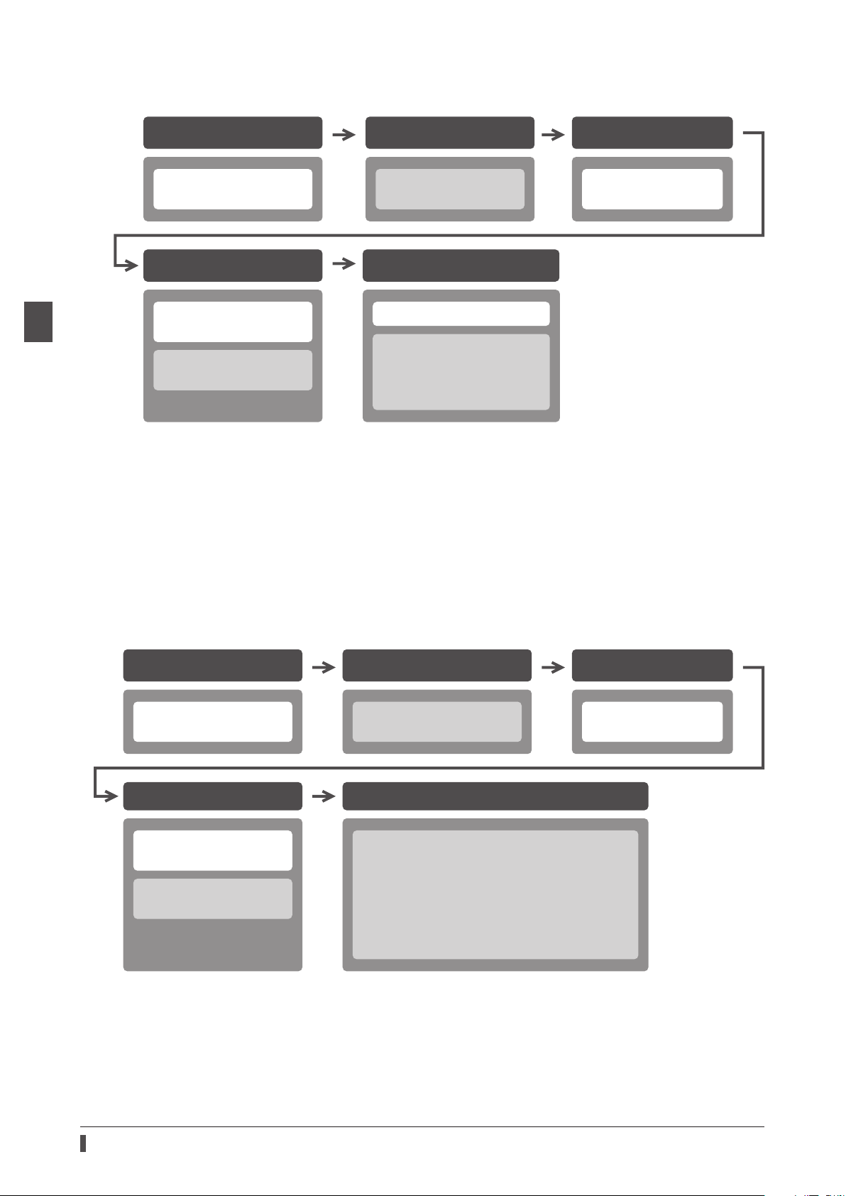
For each control method, reference destinations are indicated according to the ow of use.
Included or not included
with product
Included
Not included
Not included
with product
Series products. Refer to the OPERATING MANUAL AZ Series
AZ
1 Introduction
How to read reference destinations
The title name of the operating manual is described in the reference destination.
The title number described in the reference destination may be changed. Use the title name when
checking the reference destination.
Setting of parameters
4 Implicit communication
5 Parameter ID lists
4 Parameters
7 Address/code lists
Procedure
Reference destination in this manual
Reference destination in
OPERATING MANUAL AZ Series Function Editio
9
Page 10
Operating manuals
When controlling via EtherNet/IP
1 Introduction
Installation and connection
2 AC power input type
3 DC power input type
Setting of parameters
4 Implicit communication
5 Parameter ID lists
4 Parameters
7 Address/code lists
*1 When a motorized actuator is used, the following contents cannot be operated via EtherNet/IP. Use the support
software
· Copying the xed value (parameter) of the ABZO sensor to a driver
· Creation of recovery data le and method of recovery
*2 Refer to this manual for “power removable function.”
· When the AC power input driver is used: p.40
· When the DC power input driver is used: p.71
*3 Refer to this manual for “LEDs of the driver.”
· When the AC power input driver is used: p.22
· When the DC power input driver is used: p.54
MEXE02
.
Before starting operation
1 Before starting
operation *1
Operation
4 Implicit communication
2 Operation
3 I/O signals *2
8 Measures for various cases
11 Appendix *3
Setting of IP address
2 AC power input type
3 DC power input type
When controlling by inputting pulse signals
Before starting operationInstallation and connection Setting of IP address
2 AC power input type
3 DC power input type
Setting of parameters
4 Implicit communication
5 Parameter ID lists
4 Parameters
7 Address/code lists
*1 When a motorized actuator is used, the following contents cannot be operated via EtherNet/IP. Use the support
software
· Copying the xed value (parameter) of the ABZO sensor to a driver
· Creation of recovery data le and method of recovery
*2 Refer to this manual for “LEDs of the driver.”
· When the AC power input driver is used: p.22
· When the DC power input driver is used: p.54
MEXE02
.
1 Before starting
operation *1
Operation
8 Measures for various cases
10 Extended setting for pulse-input operation
3 Extending settings by parameters
4 I/O signals related to pulse-input operation
5 Monitor function
6 Push-motion operation
11 Appendix *2
2 AC power input type
3 DC power input type
10
Page 11

3 Overview of the product
The AZ Series EtherNet/IP compatible driver is the dedicated driver for the AZ Series products.
Lineup
Two types of the AZ Series EtherNet/IP compatible drivers are available: AC power input type and DC power input
type.
Two types of control methods
zOperation by Implicit communication (periodic communication) of EtherNet/IP
Overview of the product
zOperation by inputting pulses
Setting methods of operation data and parameters
Operation data and parameters can be set via EtherNet/IP or using the
This manual describes how to set operation data and parameters via EtherNet/IP.
MEXE02
.
Equipped with direct data operation function
The direct data operation is a function to start operation at the same time as rewriting of the data. It can be used
when the setting of the operation data is changed frequently, such as changing the speed or travel amount according
to a load.
Equipped with power removable function (ETO function: External Torque OFF)
The power removable function is a function that stops supplying the power to the motor forcibly and puts the motor
into a non-excitation state. This function can shut o the power supplying to the motor directly on the circuit.
It can be used for the purpose to protect a worker from malfunction of the moving part when a load is set to the jig of
equipment or maintenance of the equipment is performed.
Providing the EDS File
The EDS le (Electronic Data Sheets le) is a le that describes the specic information of the EtherNet/IP compatible
products. By importing the EDS le to the setting tool of the scanner, settings of EtherNet/IP can be performed before
you receive the driver.
For details, contact your nearest Oriental Motor sales oce.
1 Introduction
11
Page 12

Safety precautions
4 Safety precautions
The precautions described below are intended to ensure the safe and correct use of the product, and to prevent the
user and other personnel from exposure to the risk of injury. Use the product only after carefully reading and fully
understanding these instructions.
Handling the product without observing the instructions that accompany a "WARNING"
symbol may result in serious injury or death.
Handling the product without observing the instructions that accompany a "CAUTION"
symbol may result in injury or property damage.
The items under this heading contain important handling instructions that the user
should observe to ensure the safe use of the product.
1 Introduction
The items under this heading contain related information and contents to gain a further
understanding of the text in this manual.
Common to AC power input driver and DC power input driver
General
•Do not use the product in explosive or corrosive environments, in the presence of ammable gases, locations
subjected to splashing water, or near combustibles. Doing so may result in re, electric shock or injury.
•Assign qualied personnel to the task of installing, wiring, operating/controlling, inspecting, and troubleshooting
the product. Failure to do so may result in re, electric shock, injury, or damage to equipment.
•Do not transport, install, connect or inspect the driver while the power is supplied. Doing so may result in electric
shock.
•Do not touch the driver while the power is on. Doing so may result in re or electric shock.
•Take measures to keep the moving part in position if the product is used in vertical operations such as elevating
equipment. Failure to do so may result in injury or damage to equipment.
•When an alarm is generated in the driver (any of the driver's protective functions is triggered), remove the cause
before clearing the alarm (protective function). Continuing the operation without removing the cause of the
problem may cause malfunction of the motor and the driver, leading to injury or damage to equipment.
Installation
•Install the driver inside an enclosure. Failure to do so may result in electric shock or injury.
•The driver is Class I equipment. When installing the driver, install it inside an enclosure so that it is out of the direct
reach of users. Be sure to ground if users can touch it. Failure to do so may result in electric shock.
12
Connection
•Always keep the power supply voltage of the driver within the specied range. Failure to do so may result in re or
electric shock.
•Connect the product securely according to the wiring diagram. Failure to do so may result in re or electric shock.
•Do not forcibly bend, pull, or pinch the cable. Doing so may result in re or electric shock.
Operation
•Turn o the main power supply and the control power supply in the event of a power failure. Failure to do so may
result in injury or damage to equipment.
•Do not turn the FREE input ON while operating the motor. Doing so may result in injury or damage to equipment.
Repair, disassembly, and modication
•Do not disassemble or modify the driver. Doing so may result in injury or damage to equipment.
Page 13

Safety precautions
AC power input driver
General
•Do not touch the terminals indicated signs on the driver’s front panel while the power is supplied because
high voltage is applied. Doing so may result in re or electric shock.
Inspection and maintenance
•Do not touch the connection terminals of the driver immediately after turning o the main power supply and the
control power supply. Before performing connection or inspection, turn o the main power supply and the control
power supply, and check the CHARGE LED has been turned o. Residual voltage may cause electric shock.
Common to AC power input driver and DC power input driver
General
•Do not use the driver beyond the specications. Doing so may result in electric shock, injury, or damage to
equipment.
•Keep your ngers and objects out of the openings in the driver. Doing so may result in re, electrical shock, or
injury.
•Do not touch the driver during operation or immediately after stopping. Doing so may result in a skin burn(s).
•Do not forcibly bend or pull the cable that is connected to the driver. Doing so may result in damage.
Installation
•Keep the area around the driver free of combustible materials. Failure to do so may result in re or a skin burn(s).
•Do not leave anything around the driver that would obstruct ventilation. Doing so may result in damage to
equipment.
Operation
•Use a motor and a driver only in the specied combination. An incorrect combination may cause a re.
•Provide an emergency stop device or emergency stop circuit externally so that the entire equipment will operate
safely in the event of a system failure or malfunction. Failure to do so may result in injury.
•Before turning on the main power supply and the control power supply, turn all input signals to the driver to OFF.
Failure to do so may result in injury or damage to equipment.
•Before rotating the motor output shaft manually (manual positioning etc.), check the FREE input of the driver is
being ON. Failure to do so may result in injury.
•When an abnormal condition has occurred, immediately stop operation to turn o the main power supply and the
control power supply. Failure to do so may result in re, electrical shock or injury.
•Take measures against static electricity when operating the switches of the driver. Failure to do so may result in the
driver malfunction or damage to equipment.
1 Introduction
AC power input driver
Operation
•For the control power supply, use a DC power supply with reinforced insulation on its primary and secondary sides.
Failure to do so may result in electric shock.
Inspection and maintenance
•Do not touch the terminals while conducting the insulation resistance measurement or dielectric strength test.
Doing so may result in electric shock.
DC power input driver
Operation
•For the main power supply and the control power supply, use a DC power supply with reinforced insulation on its
primary and secondary sides. Failure to do so may result in electric shock.
Inspection and maintenance
•Do not touch the terminals while conducting the insulation resistance measurement. Doing so may result in
electric shock.
13
Page 14
Safety precautions
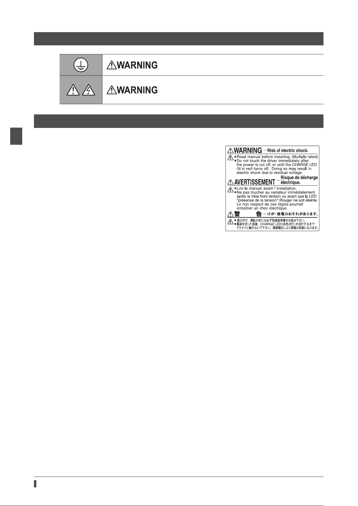
4-1 Graphical symbols on the driver's front panel
This is the protective earth terminal. Be sure to ground because
improper grounding may result in electric shock.
A high voltage is applied to the motor connector (CN3) and the main
power supply input terminals (CN4). Do not touch them while the
power is supplied. Doing so may result in re or electric shock. (AC
power input driver)
4-2 Warning indication (AC power input driver)
1 Introduction
A warning about handling precautions is described on the driver.
Be sure to observe the description contents when handling the
product.
Electrical hazard warning label
Material: PET
14
Page 15

5 Precautions for use
This chapter covers restrictions and requirements the user should consider when using the product.
Common to AC power input driver and DC power input driver
zBe sure to use our cable to connect the motor and the driver.
Check the cable models on p.45 (AC power input driver) or p.76 (DC power input driver).
zNote on connecting a power supply whose positive terminal is grounded
The USB communication connector, CN5, CN6, and CN7 connectors on the driver are not electrically insulated. When
grounding the positive terminal of the power supply, do not connect any equipment (PC, etc.) whose negative
terminal is grounded. Doing so may cause the driver and this equipment to short, damaging both. When connecting,
do not ground equipment.
zSaving data to the non-volatile memory
Do not turn o the control power supply while writing the data to the non-volatile memory, and also do not turn o
for 5 seconds after the completion of writing the data. Doing so may abort writing the data and cause an EEPROM
error alarm to generate. The non-volatile memory can be rewritten approximately 100,000 times.
zNoise elimination measures
Refer to p.35 (AC power input driver) or p.66 (DC power input driver) for the noise elimination measures.
Precautions for use
1 Introduction
AC power input driver
zWhen conducting the insulation resistance measurement or the dielectric strength test, be sure to
separate the connection between the motor and the driver.
Conducting the insulation resistance measurement or dielectric strength test with the motor and the driver
connected may result in damage to the product.
zPreventing leakage current
Stray capacitance exists between the driver’s current-carrying line and other current-carrying lines, the earth and the
motor, respectively. A high-frequency current may leak out through such capacitance, having a detrimental eect on
the surrounding equipment. The actual leakage current depends on the driver’s switching frequency, the length of
wiring between the driver and the motor, and so on. When installing an earth leakage breaker, use a product oering
resistance against high frequency current such as the one specied below.
Mitsubishi Electric Corporation: NV series
zIf vertical drive (gravitational operation) such as elevator applications is performed or if sudden start-
stop operation of a large inertial load is repeated frequently, connect our regeneration resistor
RGB100
An alarm of overvoltage may be detected depending on the operating condition of the motor. When the alarm of
overvoltage has been detected, reconsider the operating condition or use our regeneration resistor
p.28 for the connection method.
.
RGB100
. Refer to
DC power input driver
zWhen conducting the insulation resistance measurement, be sure to separate the connection between
the motor and the driver.
Conducting the insulation resistance measurement with the motor and the driver connected may result in damage to
the product.
15
Page 16

1 Introduction
16
Page 17

2 AC power input type
This part explains contents specic to the AC power input type driver.
Table of contents
1 System conguration ............................18
2 Preparation ............................................. 19
2-1 Checking the product ................................... 19
2-2 How to identify the product model ......... 19
2-3 Products possible to combine ................... 19
2-4 Information about nameplate ................... 20
2-5 Names and functions of parts .................... 20
2-6 Indication of LEDs ........................................... 22
3 Installation .............................................. 24
3-1 Installation location ....................................... 24
3-2 Installation method ....................................... 24
4 Connection ............................................. 26
4-1 Connection example ..................................... 26
4-2 Connecting the control power supply .... 27
4-3 Connecting the regeneration resistor ..... 28
4-4 Connecting the main power supply ........ 29
4-5 Grounding the driver.....................................30
4-6 Connecting the EtherNet/IP
communication cable ................................... 30
4-7 Connecting the USB cable ........................... 30
4-8 Connecting the I/O signals .......................... 31
4-9 Noise elimination measures .......................35
4-10 Conformity to the EMC Directive .............. 37
5 Setting of IP address ............................. 38
5-1 Setting method ............................................... 38
6 Power removable function
(ETO function: External torque o
function) .................................................. 40
6-1 Block diagram .................................................. 40
6-2 Wiring example ............................................... 41
6-3 Detection for error of the ETO function .. 41
6-4 Reset of ETO-mode ........................................ 42
6-5 Timing chart ..................................................... 42
6-6 To use this product safely ............................ 43
7 Inspection and maintenance .............. 44
7-1 Inspection .......................................................... 44
7-2 Warranty .............................................................44
7-3 Disposal .............................................................. 44
8 Cable ........................................................ 45
8-1 Connection cable ............................................ 45
8-2 I/O signal cable ................................................ 47
9 Accessories..............................................48
9-1 Pulse signal converter for
noise immunity ............................................... 48
9-2 Relay contact protection parts/circuits .. 48
9-3 Regeneration resistor .................................... 48
Page 18
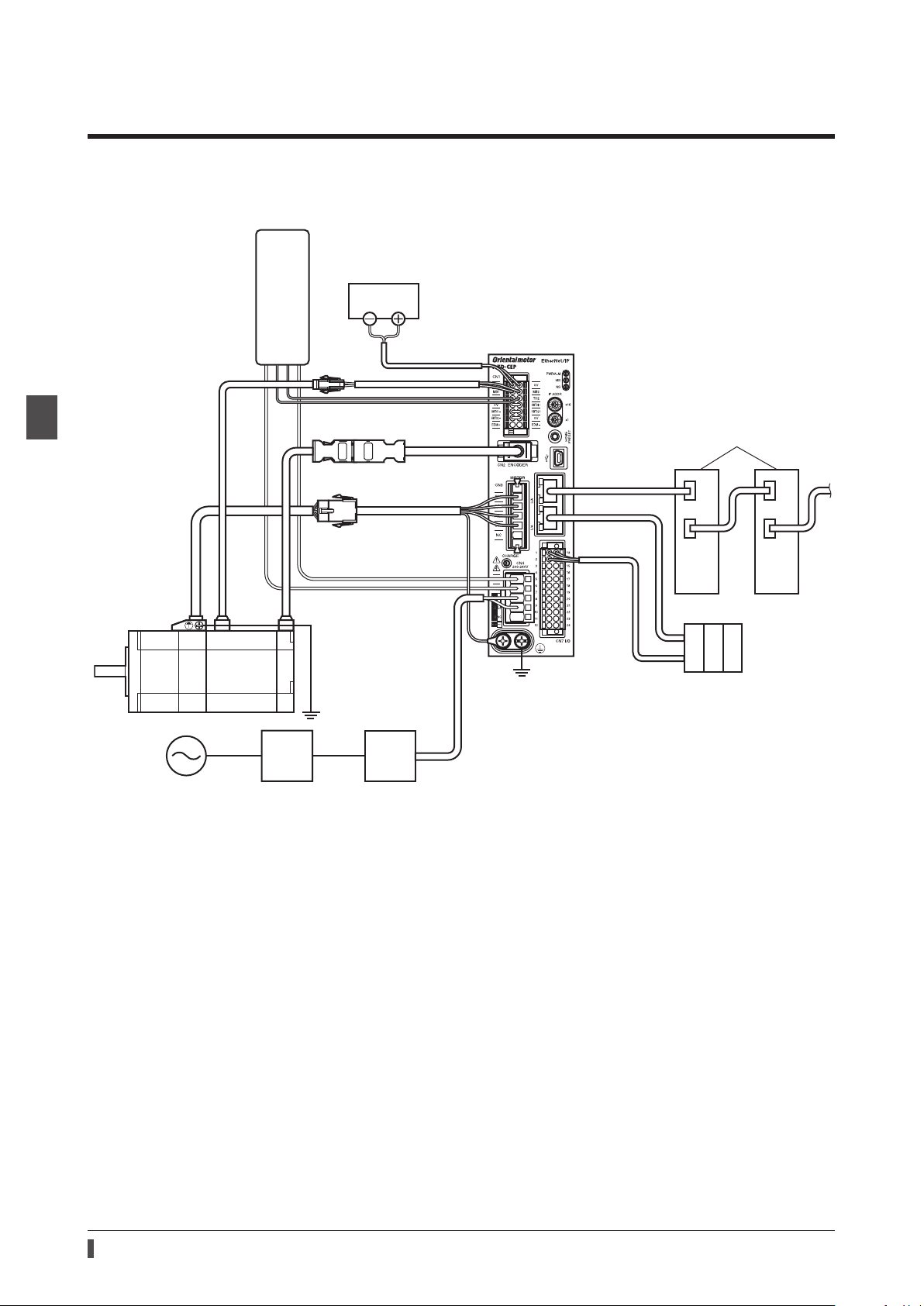
System conguration
Regeneration resistor
interrupt circuit
1 System conguration
The gure shows models for the electromagnetic brake type with single-phase 200 to 240 VAC input.
RGB100
Control
power supply
2 AC power input type
Motor
GND +24 V
Thermostat output (AWG22)
Regeneration resistor
(AWG18)
Grounding
Driver
EtherNet/IP compatible products
EtherNet/IP
EtherNet/IP
*
Scanner
Grounding
Main power
supply
Circuit breaker
or ground fault
Noise lter
* Connect when using direct I/O or sensors.
18
Page 19

2 Preparation
This chapter explains the items you should check, as well as names and functions of each part.
2-1 Checking the product
Verify that the items listed below are included. Report any missing or damaged items to the Oriental Motor sales
oce from which you purchased the product.
•Driver .................................................1 unit
•CN1 connector (14 pins) .............1 pc.
•CN4 connector (5 pins) ................1 pc.
•CN7 connector (24 pins) .............1 pc.
•Connector lever ..............................1 pc. (for CN4 connector)
•OPERATING MANUAL Driver ......1 copy
Included connector model
Preparation
Type Part number Manufacturer
CN1 connector DFMC1,5/7-ST-3,5-LR PHOENIX CONTACT GmbH & Co. KG
CN4 connector 05JFAT-SAXGDK-H5.0 J.S.T. Mfg. Co., Ltd.
CN7 connector DFMC1,5/12-ST-3,5 PHOENIX CONTACT GmbH & Co. KG
2-2 How to identify the product model
Check the model number of the driver against the number shown on the nameplate. Refer to p.20 for how to
identify the nameplate.
AZD - C EP
1 2 3
1 Series
2 Power supply input
3 Network type
AZD: AZ
A
C
EP
Series driver
: Single-phase 100-120 VAC
: Single-phase/Three-phase 200-240 VAC
: EtherNet/IP
2-3 Products possible to combine
Products with which the driver can be combined are listed below. Check the model name of the product with the
nameplate.
2 AC power input type
Power supply
type
AC input
*1 The driver described in this manual can be combined with products that begin with these model names.
*2 For these motorized actuators, the equipped motors have been evaluated to ax the CE Marking. Check the model
name of the equipped motor with the nameplate.
Product type Applicable series
Stepping motor
Motorized actuator
Series
AZ
EAS
EAC
EZS
EZSH
DGII
Series
L
Series *2
Series *2
Series *2
Series *2
Series
Model name representing
series name *1
AZM
EASM EASM4NXD005AZAC
EACM EACM4RWE15AZMC
EZSM EZSM6D005AZAC
EZSHM EZSHM6H020AZAC
DGM
DGB
LM LM4F500AZMC-10
Example of model name
AZM46AC
AZM66AC-TS10
DGM85R-AZAC
DGB85R12-AZACR
19
Page 20
Preparation
Output specication
Serial number Manufacturing date
r
Regeneration resistor thermal input terminals (
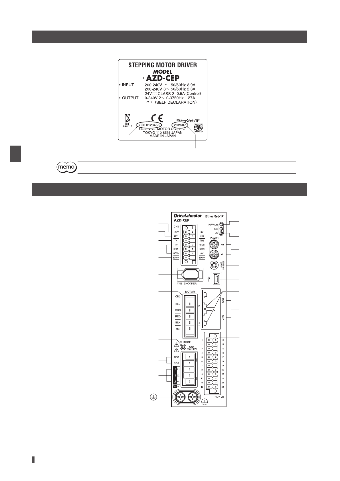
2-4 Information about nameplate
The gure shows an example.
Driver model
Input specication
2 AC power input type
The position describing the information may vary depending on the product.
2-5 Names and functions of parts
The gure shows the
Control power supply input terminals (CN1)
Electromagnetic brake terminals (CN1)
Power removal signal input terminals (CN1)
Power removal monitor output terminals (CN1)
AZD-CEP
Encoder connector (CN2)
.
CN1)
Motor connector (CN3)
PWR/ALM LED (Green/Red)
MS LED (Green/Red)
NS LED (Green/Red)
IP address setting switches
(IP ADDR ×16, ×1)
HOME PRESET switch
USB communication connecto
L/A LED (Green)
EtherNet/IP communication
connectors (CN5, CN6)
20
CHARGE LED (Red)
Regeneration resistor terminals (CN4)
Main power supply input terminals (CN4)
Protective Earth Terminals
I/O signal connector (CN7)
Page 21

Type Name Sign Description
This LED is lit while the main power supply is turned
on. After the main power has been turned o, the LED
will turn o once the residual voltage in the driver
drops to a safe level.
•This LED is lit in green while the control power supply
is turned on.
•If an alarm (protective function) is generated, the
LED will blink in red.
•If the power removable function (p.40) is triggered,
the LED will blink in green.
•If information is generated, the LED will
simultaneously blink in red and green twice. (Green
and red colors may overlap and it may be visible to
orange.)
This LED indicates the communication status of
EtherNet/IP.
These switches are used to set an IP address.
Factory setting: 00 (×16: 0, ×1: 0)
This switch is used to set the starting position (home
position) when positioning operation is performed.
Connects a PC in which the
installed. (USB2.0 mini-B port)
Connects the lead wires from the electromagnetic
brake.
Connects our regeneration resistor
regeneration resistor
the TH1 and TH2 terminals.
Connects switches or a scanner.
Connects a main power supply.
Ground using a grounding wire of AWG16 to 14 (1.25
to 2.0 mm
2
).
RGB100
LED
Switch
Connector
Terminal
CHARGE LED (Red) CHARGE
PWR/ALM LED (Green/Red) PWR/ALM
MS LED (Green/Red) MS This LED indicates the status of the driver.
NS LED (Green/Red) NS
L/A LED (Green) L/A This LED indicates the LINK/ACT status of EtherNet/IP.
IP address setting switches
HOME PRESET switch HOME PRESET
Encoder connector (CN2) ENCODER Connects the encoder.
Motor connector (CN3) MOTOR Connects the motor.
USB communication connector
EtherNet/IP communication
connectors (CN5, CN6)
I/O signal connector (CN7) I/O Connects when using direct I/O or sensors.
Control power supply input
terminals (CN1)
Electromagnetic brake
terminals (CN1)
Regeneration resistor thermal
terminals (CN1)
Power removal signal input
terminals (CN1)
Power removal monitor output
terminals (CN1)
Regeneration resistor terminals
(CN4)
Main power supply input
terminals (CN4)
Protective Earth Terminals
IP ADDR ×16
IP ADDR ×1
− Connects the EtherNet/IP communication cable.
+24V, 0V Connects a control power supply.
MB1, MB2
TH1, TH2
HWTO1+, HWTO1−
HWTO2+, HWTO2−
EDM+, EDM− Connects a scanner.
RG1, RG2 Connects our regeneration resistor
L, N, NC
L1, L2, NC
L1, L2, L3
Preparation
MEXE02
has been
RGB100
is not connected, short
RGB100
. If the
.
2 AC power input type
21
Page 22

Preparation
OFF
Blinking
500 ms 500 ms
2-6 Indication of LEDs
PWR/ALM LED
This LED indicates the status of the driver.
2 AC power input type
LED status
Green Red
Unlit Unlit The control power supply is not turned on.
Lit Unlit The control power supply is turned on.
An alarm is being generated. Details about the generated alarm can be
Unlit Blinking
Blinking Unlit
Blinking twice at the same time *
Blinking at the same time *
Lit at the same time *
Repeating "Green → Red →
Simultaneously lit → Unlit"
* Green and red colors may overlap and it may be visible to orange.
checked by counting the number of times the LED blinks. The LED is lit in green
when the alarm is reset.
The power removable function has been activated. The LED is lit in green when
the power removable function is released.
•Information is being generated. The LED is lit in green when the information
is cleared.
•Teaching, remote operation is being executed with the
lit in green when teaching, remote operation is complete.
The interlock was released by holding down the HOME PRESET switch.
The LED is lit in green when the time set in the "Extended input (EXT-IN)
interlock releasing time" parameter is elapsed.
The input signal assigned to the HOME PRESET switch is being executed. The
LED is lit in green when it is complete.
This is the driver simulation mode.
MS LED
This LED indicates the status of the driver.
Description
MEXE02
. The LED is
LED status
Green Red
Unlit Unlit The control power supply of the driver is not turned on.
Blinking Unlit The communication setting of EtherNet/IP is invalid.
Lit Unlit The driver operates properly.
Unlit Blinking
Unlit Lit An alarm that cannot be reset with EtherNet/IP or the
Blinking alternately Self-diagnosis when turning on the power is executing.
The timing to blink the LED is as follows.
ON
•An alarm that can be reset with EtherNet/IP or the
•The setting of an IP address is duplicated in the same system.
Description
MEXE02
MEXE02
was generated.
was generated.
22
Page 23

NS LED
OFF
Blinking
500 ms 500 ms
This LED indicates the communication status of EtherNet/IP.
Preparation
LED status
Green Red
Unlit Unlit
Blinking Unlit In an online state. Connection with the scanner is not established.
Lit Unlit In an online state. Connection with the scanner is being established.
Unlit Blinking Connection with the scanner became time-out.
Unlit Lit The setting of an IP address is duplicated in the same system.
Blinking alternately Self-diagnosis when turning on the power is executing.
The timing to blink the LED is as follows.
ON
•In an oine state.
•The control power supply of the driver is not turned on.
Description
2 AC power input type
L/A LED
This LED indicates the LINK/ACT status of EtherNet/IP.
LED status Description
Unlit
Blinking
Lit
•In an oine state.
•The frame of EtherNet/IP is not sent and received.
•In an online state.
•The frame of EtherNet/IP is sent and received.
•In an online state.
•The frame of EtherNet/IP is not sent and received.
23
Page 24
2 AC power input type
25 (0.98) or more
35 (1.38)
Installation
3 Installation
This chapter explains the installation location and installation method of the driver.
3-1 Installation location
The driver is designed and manufactured to be incorporated in equipment. Install it in a well-ventilated location that
provides easy access for inspection. The location must also satisfy the following conditions:
•Inside an enclosure that is installed indoors (provide vent holes)
•Operating ambient temperature: 0 to +55°C (+32 to +131 °F) (non-freezing)
•Operating ambient humidity: 85% or less (non-condensing)
•Area that is free of explosive atmosphere or toxic gas (such as sulfuric gas) or liquid
•Area not exposed to direct sun
•Area free of excessive amount of dust, iron particles or the like
•Area not subject to splashing water (rain, water droplets), oil (oil droplets) or other liquids
•Area free of excessive salt
•Area not subject to continuous vibrations or excessive shocks
•Area free of excessive electromagnetic noise (from welders, power machinery, etc.)
•Area free of radioactive materials, magnetic elds or vacuum
•Up to 1,000 m (3,300 ft.) above sea level
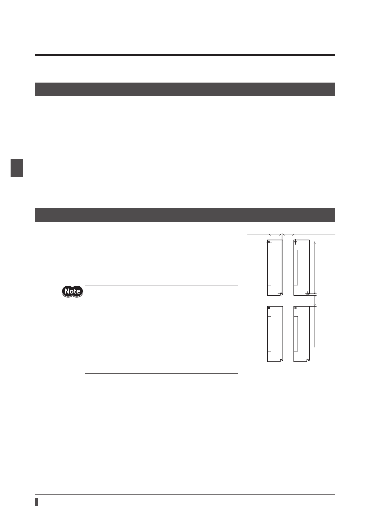
3-2 Installation method
The driver is designed so that heat is dissipated via air convection and
conduction through the enclosure. Install the driver to a at metal plate (*)
oering high heat conductivity. When installing drivers, provide clearances
of at least 25 mm (0.98 in.) in the horizontal and vertical directions between
the driver and enclosure or other equipment within the enclosure.
When installing the driver, use two screws (M4, not included) to secure the
driver through the mounting holes.
* Material: Aluminum, 200×200×2 mm (7.87×7.87×0.08 in.) or equivalent
•Install the driver inside an enclosure whose pollution degree
is 2 or better environment, or whose degree of protection is
IP54 minimum.
•Do not install any equipment that generates a large amount
of heat or noise near the driver.
•Do not install the driver underneath a scanner or other
equipment vulnerable to heat.
•If the ambient temperature of the driver exceeds 55 °C
(131 °F), improve the ventilation condition such as providing
forced cooling by using fans or creating spaces between the
drivers.
•Be sure to install the driver vertically (in vertical position).
150 (5.91) 25 (0.98) or more
Unit: mm (in.)
24
Page 25
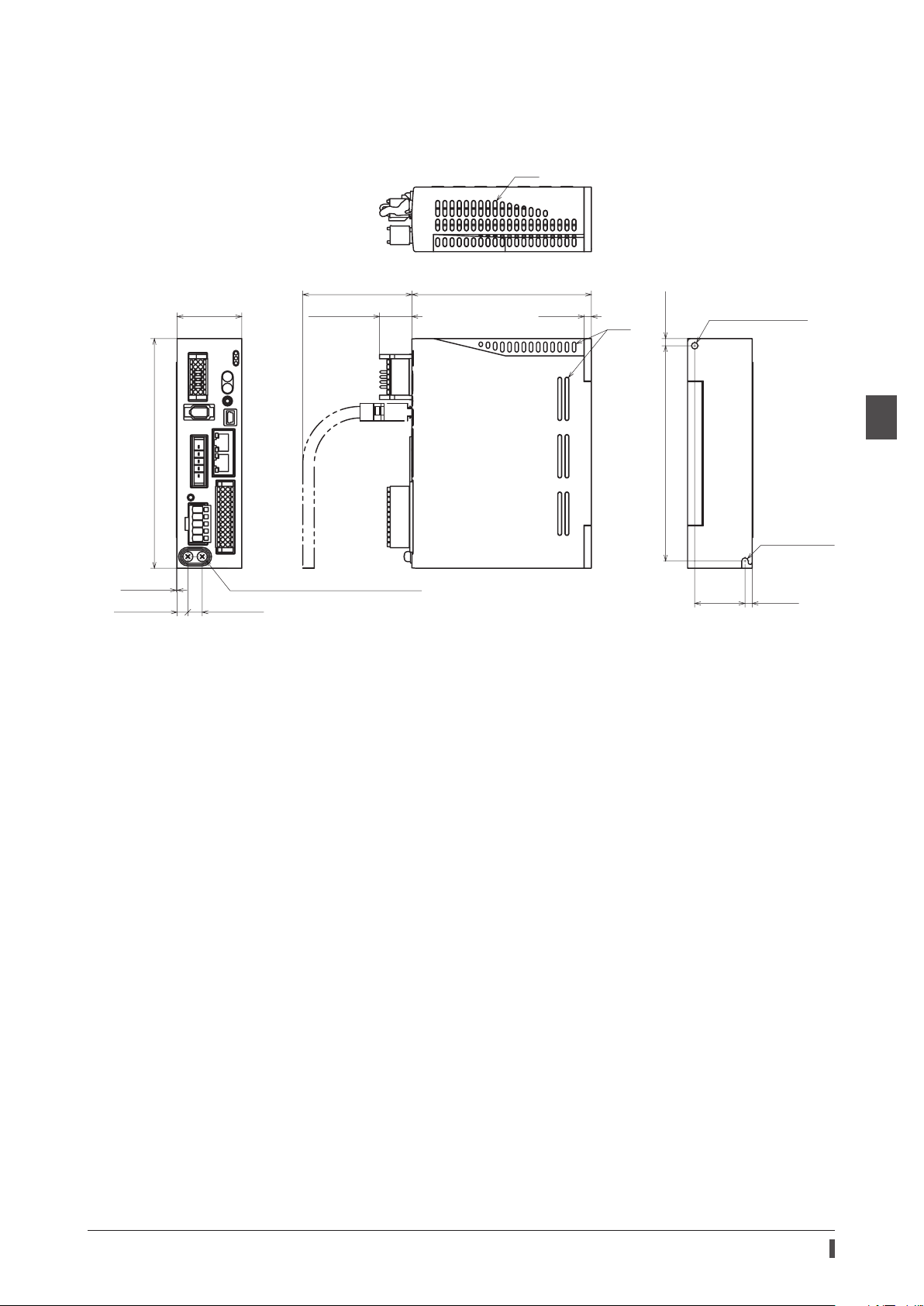
Dimensions
[7.5 (0.30)]
Slits
R2.25 (0.089)
•Unit: mm (in.)
•Mass: 0.68 kg (1.5 lb.)
Installation
160 (6.30)
0.5 (0.02)
45 (1.77)
[10 (0.39)]
[76 (2.99)]
[22.5 (0.89)]
Protective Earth Terminals 2×M4
125 (4.92)
5 (0.20)
Slits
150 (5.91) 5 (0.20)
ø4.5 (0.177) hole
35
(1.38)
5 (0.20)
2 AC power input type
25
Page 26
Connection
Grounding
4 Connection
This chapter explains a connection example of a driver and a motor, connection methods of power supplies and the
regeneration resistor
The installation and wiring methods in compliance with the EMC Directive as well as protection against noise are also
explained.
RGB100
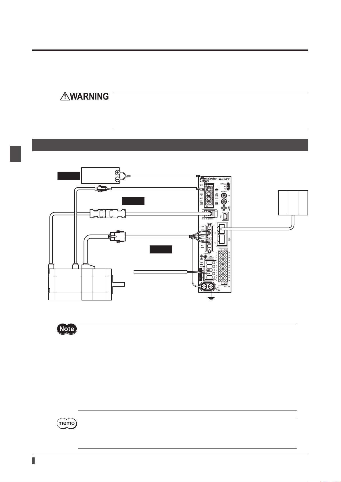
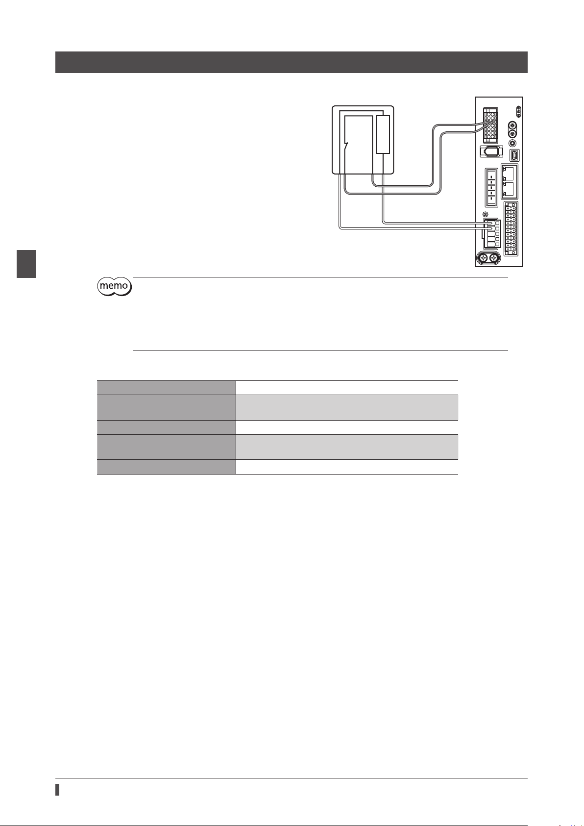
4-1 Connection example
, the grounding method, and others.
•For protection against electric shock, do not turn on the power supply until the wiring
is completed.
•A high voltage is applied to the motor connector (CN3) and the main power supply
input terminals (CN4). Do not touch them while the power is on. Doing so may result in
re or electric shock.
2 AC power input type
The gure shows models for the electromagnetic brake type with single-phase 200 to 240 VAC input.
Required
*1 Purchase it separately.
*2 Use the cable for encoder when the length of the encoder cable of motor is not enough.
Control
power supply
Cable for electromagnetic brake *1
Required
Connect to +24V and 0V
Connect to MB1 and MB2
Connect to CN2
Cable for encoder *1 *2
Connect to CN3
Cable for motor *1
Required
Connect to L1 and L2
Main power supply
Single-phase 200-240 V
Connect to CN5 or CN6
EtherNet/IP
communication cable
Scanner
26
•Connect the connectors securely. Insecure connections may cause malfunction or damage to the
motor or driver.
•Before connecting or disconnecting a connector, turn o the main power supply and the control
power supply, and check the CHARGE LED has been turned o. Residual voltage may cause electric
shock.
•The lead wires of the "cable for electromagnetic brake" have polarities, so connect them in the
correct polarities. If the lead wires are connected with their polarities reversed, the electromagnetic
brake will not operate properly.
•Do not wire the power supply cable of the driver in the same cable duct with other power lines or
motor cable. Doing so may cause malfunction due to noise.
•Keep 20 m (65.6 ft.) or less for the wiring distance between the motor and the driver. To extend
more than 20 m (65.6 ft.) may result in the driver heat generation or increase of the electrical noise
emitted from the product.
•A control power supply is required with or without an electromagnetic brake. Be sure to connect it.
•When pulling o the motor cable, do so while pressing the latches on the connector with ngers.
•When installing the motor on a moving part, use a exible cable oering excellent exibility. Refer
to p.45 for the model name.
Page 27
Electrical wire size
Button of the orange color
HW
HW
O1+
O2+
Jumper wire
Connector Terminal symbol Recommended wire size
+24V, 0V, MB1, MB2, TH1, TH2,
CN1
CN4 RG1, RG2, L, N, L1, L2, L3 Stranded wire or solid wire AWG18 to 14 (0.75 to 2.0 mm
CN7 − Stranded wire or solid wire AWG24 to 16 (0.2 to 1.25 mm
HWTO1+, HWTO1−, HWTO2+,
HWTO2−, EDM+, EDM−
Stranded wire or solid wire AWG24 to 16 (0.2 to 1.25 mm
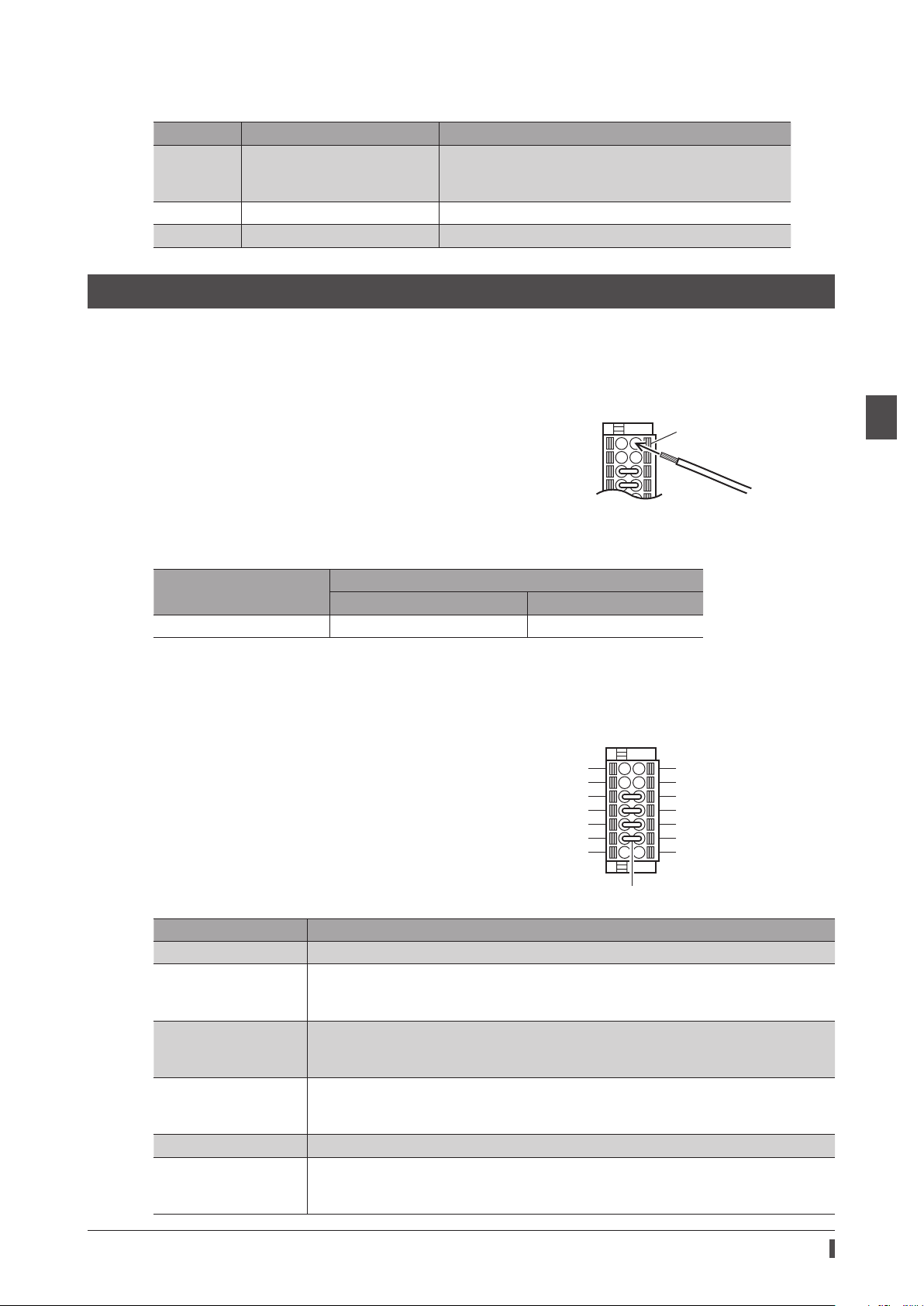
4-2 Connecting the control power supply
Wiring method of CN1 connector
•Applicable lead wire: AWG24 to 16 (0.2 to 1.25 mm2)
•Stripping length of wire insulation: 10 mm (0.39 in.)
1. Strip the insulation of the lead wire.
2. Insert the lead wire while pushing the button of the orange color with
a slotted screwdriver.
3. After having inserted, release the button to secure the lead wire.
Lead wire
Connection
2
)
2
)
2
)
2 AC power input type
Power supply current capacity
Input power supply voltage
24 VDC±5% *1 0.25 A 0.5 A *2
*1 When an electromagnetic brake motor is used, if the wiring distance between the motor and the driver is extended
to 20 m (65.6 ft.) using our cable, the input voltage is 24 VDC±4%.
*2 The
AZM46
Pin assignment
There are two terminals for 0 V: One for control power supply
and the other is for internal connection. Check each position in
the gure and table shown.
Sign Description
+24V, 0V *1 Connects a control power supply.
MB1, MB2
TH1, TH2
HWTO1+, HWTO1−
HWTO2+, HWTO2−
EDM+, EDM− Connects a scanner.
+V, 0V *2
type is 0.33 A.
Power supply current capacity
Without electromagnetic brake With electromagnetic brake
+24V
MB1
TH1
+V
TO1
-
TO2
-
EDM+
Connects the lead wires from the electromagnetic brake.
MB1: Electromagnetic brake− (Black)
MB2: Electromagnetic brake+ (White)
Connects the signal lines of our regeneration resistor
If the regeneration resistor is not used, connect a jumper wire (included) between the
terminals as shown in the gure.
Connects switches or a scanner.
If the power removal function is not used, connect a jumper wire (included) between the
terminals as shown in the gure.
These are for internal connection. Do not connect anything.
If the power removal function is not used, connect a jumper wire (included) between the
terminals as shown in the gure.
RGB100
0V *1
MB2
TH2
HWT
HWT
0V *2
EDM
.
-
27
Page 28
Connection
Regeneration resistor
4-3 Connecting the regeneration resistor
If vertical drive (gravitational operation) such as elevating
applications is performed or if sudden start-stop operation
of a large inertial is repeated frequently, connect our
regeneration resistor
•The two thin lead wires (AWG22: 0.3 mm
regeneration resistor are the thermostat outputs.
Connect them to the TH1 and TH2 using the CN1
connector.
•Regenerative current ows through the two thick lead
wires (AWG18: 0.75 mm
Connect them to the RG1 and RG2 using the CN4
connector.
RGB100
.
2
) of the regeneration resistor.
2
) of the
RGB100
150 °C (302 °F)
[N.C.]
R:150 Ω
AWG22
To TH1 and TH2
CN1
CN4
To RG1 and RG2
AWG18
2 AC power input type
•When connecting the regeneration resistor, be sure to remove the jumper wire from the CN1
connector.
•If the allowable power consumption of the regeneration resistor exceeds the allowable level, the
thermostat will be triggered to generate an alarm of regeneration resistor overheat. When an alarm
of regeneration resistor overheat is generated, turn o the main power supply and check the error
content.
zRegeneration resistor specications
Model
Allowable power consumption
Resistance value 150 Ω
Thermostat operating temperature
Thermostat electrical rating 120 VAC 4 A or 30 VDC 4A (minimum current 5 mA)
* Install the regeneration resistor in a location where heat dissipation capacity equivalent to a level achieved with a
aluminum plate [350×350×3 mm (13.78×13.78×0.12 in.)] is ensured.
RGB100
Continuous regenerative power: 50 W *
Instantaneous regenerative power: 600 W
Operation: Opens at 150±7 °C (302±12.6 °F)
Reset: Closes at 145±12 °C (293±21.6 °F) [normally closed]
28
Page 29
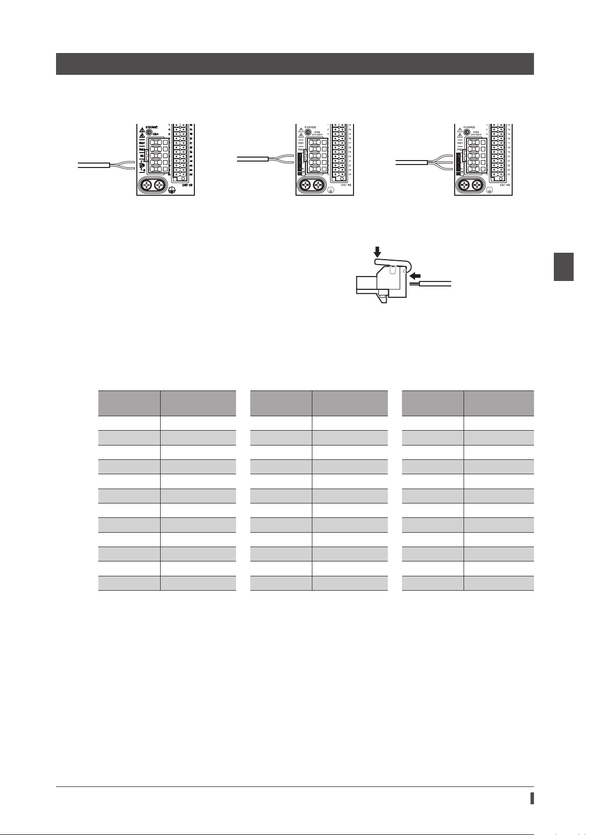
4-4 Connecting the main power supply
Single-phase 100-120 V -15% to +6%
50/60
Single-phase 200-240 V -15% to +6%
Three-phase 200-240 V -15% to +6%
Co
L and
e
Connector lever
The connecting method varies depending on the power supply specication.
Connection
Hz
nnect to
N
50/60 Hz
Connect to
L1 and L2
50/60 Hz
Connect to
L1, L2 and L3
Wiring method of CN4 connector
•Applicable lead wire: AWG18 to 14 (0.75 to 2.0 mm2)
•Stripping length of wire insulation: 9 mm (0.35 in.)
1. Insert the connector lever.
2. Insert the lead wire while pushing down the connector lever.
Lead wir
Power supply current capacity
The current capacity for the power supply varies depending on the product combined.
Check the current capacity in reference to the equipped motor model name when using the
EZS
Series, or
EZSH
Series.
zSingle-phase 100-120 VAC zSingle-phase 200-240 VAC zThree-phase 200-240 VAC
Model
AZM46
AZM48
AZM66
AZM69
AZM98
AZM911
DGB85
DGM85
DGM130
DGM200
LM2
LM4
Power supply
current capacity
2.7 A or more
2.7 A or more
3.8 A or more
5.4 A or more
5.5 A or more
6.4 A or more
2.7 A or more
2.7 A or more
3.8 A or more
6.4 A or more
3.8 A or more
3.8 A or more
Model
AZM46
AZM48
AZM66
AZM69
AZM98
AZM911
DGB85
DGM85
DGM130
DGM200
LM2
LM4
Power supply
current capacity
1.7 A or more
1.6 A or more
2.3 A or more
3.3 A or more
3.3 A or more
3.9 A or more
1.7 A or more
1.7 A or more
2.3 A or more
3.9 A or more
2.3 A or more
2.3 A or more
Model
AZM46
AZM48
AZM66
AZM69
AZM98
AZM911
DGB85
DGM85
DGM130
DGM200
LM2
LM4
EAS
Series,
Power supply
current capacity
1.0 A or more
1.0 A or more
1.4 A or more
2.0 A or more
2.0 A or more
2.3 A or more
1.0 A or more
1.0 A or more
1.4 A or more
2.3 A or more
1.4 A or more
1.4 A or more
EAC
2 AC power input type
Series,
29
Page 30
Connection
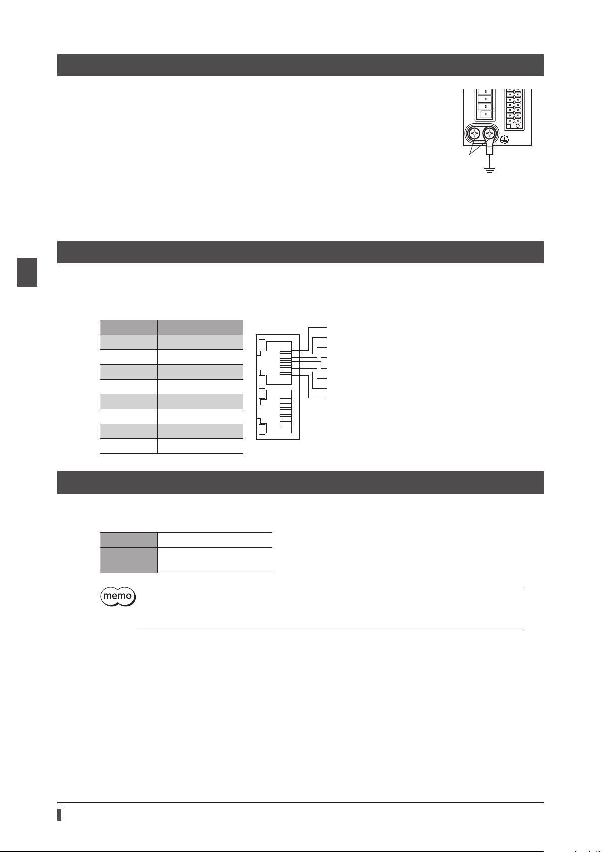
(Ground either of the terminals.)
Grounding
TXP
N
N
4-5 Grounding the driver
Two Protective Earth Terminals (screw size: M4) are provided on
the driver. Be sure to ground one of the Protective Earth
Terminals. Either of the two Protective Earth Terminals can be
used for grounding the driver.
•Grounding wire: AWG16 to 14 (1.25 to 2.0 mm
•Tightening torque: 1.2 N·m (170 oz-in)
Connect the grounding wire of the "cable for motor" to the
other terminal to ground the motor.
Do not share the grounding wire with a welder or any other
power equipment.
When grounding the Protective Earth Terminal, use a round
terminal and secure the grounding point near the driver.
2
)
Protective Earth Terminals
4-6 Connecting the EtherNet/IP communication cable
2 AC power input type
Connect the EtherNet/IP communication cable to the EtherNet/IP communication connector (CN5, CN6).
Pin assignment
Signal name Description
TXP Transmitted data+
TXN Transmitted data−
RXP Received data+
N.C. −
N.C. −
RXN Received data−
N.C. −
N.C. −
4-7 Connecting the USB cable
Using a USB cable of the following specication, connect a PC in which the
communication connector.
Specication USB2.0 (full speed)
Cable
Length: 3 m (9.8 ft.) or less
Shape: A to mini B
TX
RXP
N.C.
N.C.
RX
N.C.
N.C.
MEXE02
has been installed to the USB
30
•Connect the driver and PC directly using the USB cable.
•In large electrically noisy environments, use the USB cable with a ferrite core or install a ferrite core
to the USB cable.
Page 31

4-8 Connecting the I/O signals
Button of the orange color
13
12 24
Connect when using direct I/O or sensors.
Wiring method of CN7 connector
•Applicable lead wire: AWG24 to 16 (0.2 to 1.25 mm2)
•Stripping length of wire insulation: 10 mm (0.39 in.)
1. Strip the insulation of the lead wire.
2. Insert the lead wire while pushing the button of the orange color
with a slotted screwdriver.
3. After having inserted, release the button to secure the lead wire.
Be certain the I/O signal cable is as short as possible. The maximum input frequency will decrease as
the cable length increases.
Connection
Lead wire
Pin assignment
Pin
No.
10 OUT-COM Output common 22 GND GND
11 ASG+ Phase A pulse output + 23 ASG− Phase A pulse output −
12 BSG+ Phase B pulse output + 24 BSG− Phase B pulse output −
Signal
name *
1
2
3 IN0
4 IN2 Control input 2 (STOP) 16 IN3
5
6 IN4
7 OUT0
8 OUT2
9 OUT4
CW+
[PLS+]
CCW+
[DIR+]
IN-COM
0-3
Description *
CW pulse input +
[Pulse input +]
CCW pulse input +
[Rotation direction
switching input +]
Control input 0
(ZHOME)
IN0 to IN3 inputs
common
Control input 4
(FW-JOG)
Control output 0
(HOME-END)
Control output 2
(PLS-RDY)
Control output 4
(MOVE)
1
Pin
No.
13
14
15 IN1 Control input 1 (FREE)
17
18 IN5
19 OUT1
20 OUT3
21 OUT5
Signal
name *
CW−
[PLS−]
CCW−
[DIR−]
IN-COM
4-5
Description *
CW pulse input −
[Pulse input −]
CCW pulse input −
[Rotation direction
switching input −]
Control input 3
(ALM-RST)
IN4, IN5 inputs
common
Control input 5
(RV-JOG)
Control output 1
(IN-POS)
Control output 3
(READY)
Control output 5
(ALM-B)
2 AC power input type
* Values in brackets [ ] are signals when the 1-pulse input mode is set. Values in parentheses ( ) are initial values.
31
Page 32

Connection
Scanner Driver
Connection example with a current sink output circuit
zWhen the pulse input circuit of the driver is of line driver type
The pin No.1, No.2, No.13, and No.14 are only available to the pulse input. Other functions cannot be assigned.
Twisted pair cable
0 V
2 AC power input type
24 VDC
0 V
24 VDC
0 V
12 to 24 VDC
R0
10 mA or less →
CW+ [PLS+]
[PLS-]
-
CW
CCW+ [DIR+]
-
[DIR-]
CCW
IN0 (ZHOME)
IN1 (FREE)
IN2 (STOP)
IN3 (ALM-RST)
IN-COM 0-3
IN4 (FW-JOG)
IN5 (RV-JOG)
IN-COM 4-5
OUT0 (HOME-END)
13
14
15
16
18
17
1
2
3
4
5
6
7
470 Ω
470 Ω
270 Ω
270 Ω
270 Ω
270 Ω
4.7 kΩ 2.2 kΩ
4.7 kΩ 2.2 kΩ
4.7 kΩ 2.2 kΩ
4.7 kΩ 2.2 kΩ
4.7 kΩ
4.7 kΩ
5.6 kΩ
5.6 kΩ
2.2 kΩ
2.2 kΩ
R0
R0
R0
R0
R0
0 V
0 V
* Values in brackets [ ] are signals when the 1-pulse input mode is set. Values in parentheses ( ) are initial values.
Twisted pair cable
OUT1 (IN-POS)
OUT2 (PLS-RDY)
OUT3 (READY)
OUT4 (MOVE)
OUT5 (ALM-B)
OUT-COM
ASG+
ASG
BSG+
BSG
GND
19
8
Output saturated
20
9
21
10
11
23
12
24
22
voltage 3 V max.
26C31 or equivalent
0 V
32
Page 33

•Use input signals at 24 VDC.
DriverScanner
DriverScanner
•Use output signals at 12 to 24 VDC, 10 mA or less. If the current exceeds 10 mA, connect an
external resistor R0 so that the current becomes 10 mA or less.
•The saturated voltage of the output signal is 3 VDC maximum.
zWhen the pulse input circuit of the driver is of open collector type
The pin No.1, No.2, No.13, and No.14 are only available to the pulse input. Other functions cannot be assigned.
Use the CW [PLS] input and CCW [DIR] input at 5 to 24 VDC. When using signals at 24 VDC, connect
an external resistor R1 (1.2 kΩ to 2.2 kΩ, 0.5 W or more). When using signals at 5 VDC, apply the
voltage directly.
When the voltage of pulse input signals is 5 VDC
Connection
5 VDC
0 V
Twisted pair cable
CW+ [PLS+]
-
[PLS-]
CW
CCW+ [DIR+]
-
[DIR-]
CCW
* Values in brackets [ ] are signals when the 1-pulse input mode is set.
13
14
1
2
470 Ω
470 Ω
270 Ω
270 Ω
270 Ω
270 Ω
5.6 kΩ
5.6 kΩ
2 AC power input type
When the voltage of pulse input signals is 24 VDC
24 VDC
0 V
Twisted pair cable
R1
1.2 kΩ to 2.2 kΩ
0.5 W or more
R1
1.2 kΩ to 2.2 kΩ
0.5 W or more
CW+ [PLS+]
CW
-
[PLS-]
CCW+ [DIR+]
-
[DIR-]
CCW
* Values in brackets [ ] are signals when the 1-pulse input mode is set.
13
14
1
2
470 Ω
470 Ω
270 Ω
270 Ω
270 Ω
270 Ω
5.6 kΩ
5.6 kΩ
33
Page 34

Connection
DriverScanner
Connection example with a current source output circuit
zWhen the pulse input circuit of the driver is of line driver type
The pin No.1, No.2, No.13, and No.14 are only available to the pulse input. Other functions cannot be assigned.
2 AC power input type
270 Ω
270 Ω
270 Ω
270 Ω
4.7 kΩ 2.2 kΩ
4.7 kΩ 2.2 kΩ
4.7 kΩ 2.2 kΩ
4.7 kΩ 2.2 kΩ
4.7 kΩ 2.2 kΩ
4.7 kΩ 2.2 kΩ
13
14
15
16
18
17
1
2
3
4
5
6
7
470 Ω
470 Ω
Twisted pair cable
0 V
24 VDC
0 V
24 VDC
0 V
12 to 24 VDC
R0
← 10 mA or less
CW+ [PLS+]
[PLS-]
-
CW
CCW+ [DIR+]
-
[DIR-]
CCW
IN0 (ZHOME)
IN1 (FREE)
IN2 (STOP)
IN3 (ALM-RST)
IN-COM 0-3
IN4 (FW-JOG)
IN5 (RV-JOG)
IN-COM 4-5
OUT0 (HOME-END)
5.6 kΩ
5.6 kΩ
R0
R0
R0
R0
R0
0 V
Twisted pair cable
0 V
* Values in brackets [ ] are signals when the 1-pulse input mode is set. Values in parentheses ( ) are initial values.
OUT1 (IN-POS)
OUT2 (PLS-RDY)
OUT3 (READY)
OUT4 (MOVE)
OUT5 (ALM-B)
OUT-COM
ASG+
ASG
BSG+
BSG
GND
19
8
Output saturated
20
9
21
10
11
23
12
24
22
voltage 3 V max.
26C31 or equivalent
0 V
34
Page 35

•Use input signals at 24 VDC.
Scanner
Driver
Scanner
Driver
•Use output signals at 12 to 24 VDC, 10 mA or less. If the current exceeds 10 mA, connect an
external resistor R0 so that the current becomes 10 mA or less.
•The saturated voltage of the output signal is 3 VDC maximum.
zWhen the pulse input circuit of the driver is of open collector type
The pin No.1, No.2, No.13, and No.14 are only available to the pulse input. Other functions cannot be assigned.
Use the CW [PLS] input and CCW [DIR] input at 5 to 24 VDC. When using signals at 24 VDC, connect
an external resistor R1 (1.2 kΩ to 2.2 kΩ, 0.5 W or more). When using signals at 5 VDC, apply the
voltage directly.
When the voltage of pulse input signals is 5 VDC
5 VDC
Connection
270 Ω
270 Ω
270 Ω
270 Ω
13
14
1
2
470 Ω
470 Ω
CW+ [PLS+]
-
[PLS-]
0 V
Twisted pair cable
CW
CCW+ [DIR+]
-
[DIR-]
CCW
* Values in brackets [ ] are signals when the 1-pulse input mode is set.
5.6 kΩ
2 AC power input type
5.6 kΩ
When the voltage of pulse input signals is 24 VDC
24 VDC
0 V
1.2 kΩ to 2.2 kΩ
0.5 W or more
R1
1.2 kΩ to 2.2 kΩ
0.5 W or more
R1
CW+ [PLS+]
CW
CCW+ [DIR+]
CCW
Twisted pair cable
* Values in brackets [ ] are signals when the 1-pulse input mode is set.
-
-
[PLS-]
[DIR-]
13
14
1
2
470 Ω
470 Ω
270 Ω
270 Ω
270 Ω
270 Ω
5.6 kΩ
5.6 kΩ
4-9 Noise elimination measures
There are two types of electrical noises: One is a noise to invade into the driver from the outside and cause the driver
malfunction, and the other is a noise to emit from the driver and cause peripheral equipments malfunction.
For the noise that is invaded from the outside, take measures to prevent the driver malfunction. It is needed to take
adequate measures because signal lines are very likely to be aected by the noise.
For the noise that is emitted from the driver, take measures to suppress it.
Measures against electrical noise
There are the following three methods mainly to take measures against the electrical noise.
zNoise suppression
•When relays or electromagnetic switches are used, use noise lters or CR circuits to suppress surge generated by
them.
•Use our connection cable when extending the wiring distance between the motor and the driver. Refer to p.45
for the model name. This is eective in suppressing the electrical noise emitted from the motor.
•Cover the driver by a metal plate such as aluminum. This is eective in shielding the electrical noise emitted from
the driver.
35
Page 36

2 AC power input type
Cable clamp
Shielded cable
Connection
z Prevention of noise propagation
•Connect a noise lter to the power supply cable of the driver.
•Place the power lines, such as the motor and the power supply cables, keeping a distance of 200 mm (7.87 in.) or
more from the signal lines, and also do not bundle them or wire them in parallel. If a power cable and a signal
cable have to cross, cross them at a right angle.
•Use shielded twisted pair cables for power lines and signal lines.
•Keep cables as short as possible without coiling and bundling extra lengths.
•Grounding multiple points will increase eect to block electrical noise because impedance on the grounding
points is decreased. However, ground them so that a potential dierence does not occur among the grounding
points. I/O signal cables that includes a ground wire are provided in our product line. Refer to p.47 for the model
name.
•To ground a shielded cable, use a metal cable clamp that can maintain
contact with the entire circumference of the shielded cable, and ground
as near the product as possible.
zSuppression of eect by noise propagation
•Loop the noise propagated cable around a ferrite core. Doing so will prevent the propagated noise invades into
the driver or emits from the driver. The frequency band in which an eect by the ferrite core can be seen is
generally 1 MHz or more. Check the frequency characteristics of the ferrite core used. When increasing the eect of
noise attenuation by the ferrite core, loop the cable a lot.
•Change the transmission method of the pulse signal to the line driver type in order to prevent noise eects. If the
pulse signal of the scanner is of the open collector type, use our pulse signal converter for noise immunity. Refer to
p.48 for the model name.
Noise suppression parts
z Noise lter
•Connect the following noise lter (or equivalent) to the power line. Doing so will prevent the propagated noise
through the power line. Install the noise lter as close to the driver as possible.
Manufacturer
SOSHIN ELECTRIC CO., LTD. HF2010A-UPF HF3010C-SZA
Schaner EMC FN2070-10-06 FN3025HP-10-71
•Use the AWG18 (0.75 mm
using a cable clamp or others so that the cable does not come o the enclosure.
•Place the input cable as far apart as possible from the output cable, and do not wire the cables in parallel. If the
input and output cables are placed at a close distance or if they are wired in parallel, the noise in the enclosure
aects the power cable through stray capacitance, and the noise suppressing eect will reduce.
•Connect the ground terminal of the noise lter to the grounding point, using as thick and short a wire as possible.
•When connecting a noise lter inside an enclosure, wire the input cable of the noise lter as short as possible.
Wiring in long distance may reduce the noise suppressing eect.
Single-phase 100-120 VAC
Single-phase 200-240 VAC
2
) or thicker wire for the input and output cables of the noise lter, and secure rmly
Three-phase 200-240 VAC
Our noise suppression products
Check the model names on p.47 and p.48.
zI/O signal cable
This is a shielded cable for good noise immunity to connect the driver and scanner. The ground wire useful to
grounding is extracted from both ends of the cable. The EMC measures are conducted using our I/O signal cable.
zPulse signal converter for noise immunity
This product converts a pulse signal, which is output from the open collector output, to a pulse signal for good noise
immunity by outputting the pulse signal again from the dierential output.
zSurge suppressor
This product is eective to suppress the surge which occurs in a relay contact part. Connect it when using a relay or
electromagnetic switch. CR circuit for surge suppression and CR circuit module are provided.
36
Page 37

4-10 Conformity to the EMC Directive
Motor
* It is the cable in our products.
Eective measures must be taken against the EMI that the motor and the driver may give to adjacent control-system
equipment, as well as the EMS of the motor and the driver itself, in order to prevent a serious functional impediment
in the machinery. The use of the following installation and wiring methods will enable the motor and the driver to be
compliant with the EMC directive. Refer to p.169 for the applicable standards.
Oriental Motor conducts EMC measurements on its motors and drivers in accordance with “Example of installation
and wiring”
The user is responsible for ensuring the machine’s compliance with the EMC Directive, based on the installation and
wiring explained next.
zConnecting the noise lter
In large electrically noisy environments, connect a noise lter. Refer to “Noise lter” on p.36 for details.
zConnecting the control power supply
Use a power supply compliant with the EMC Directive for the control power supply.
Wire and ground the power supply over the shortest possible distance using a shielded cable.
Refer to “Prevention of noise propagation” on p.36 for how to ground the shielded cable.
zConnecting the motor cable
Use our connection cable when extending the wiring distance between the motor and the driver. Refer to p.45 for
the model name.
zConnecting the signal cable
Refer to “Prevention of noise propagation” on p.36.
Connection
2 AC power input type
zGrounding method
•The cable used to ground the motor, the driver, and the noise lter must be as thick and short as possible so that
no potential dierence is generated.
•Choose a large, thick and uniformly conductive surface for the grounding point.
•When installing the motor and the driver, connect their Protective Earth Terminals. Refer to the p.30 for the
grounding method.
z Example of installation and wiring
AC
Noise
lter
Control power
supply (24 VDC)
AC
Shielded
cable
Cable for
electromagnetic brake *
Cable
clamp
Cable
clamp
Cable for encoder *
Cable for motor *
Noise
lter
Driver
Cable
clamp
I/O signal
cable *
EtherNet/IP
communication cable
Cable
clamp
Scanner
Grounded panel
symbol indicate the grounding.
is a shielded box.
The driver uses parts that are sensitive to electrostatic charge. Take measures against static electricity
since static electricity may cause the driver to malfunction or suer damage.
37
Page 38

Setting of IP address
Default gateway
s
5 Setting of IP address
This chapter explains how to set the IP address.
Set the “subnet mask” and the “default gateway” together with the IP address.
5-1 Setting method
The setting method varies depending on the setting range of the IP address.
2 AC power input type
First octet
IP address
Subnet mask
XXX.
XXX.
XXX.
Second octet
XXX.
XXX.
XXX.
Setting range when setting only the fourth octet of IP address
Setting range when setting from the rst octet to the fourth octet of IP addres
Third octet
XXX.
XXX.
XXX.
Fourth octet
XXX
XXX
XXX
When setting only the fourth octet of the IP address
Set an IP address with the IP address setting switches of the driver, and the subnet mask and the default gateway with
the parameters.
zSetting of IP address
Set the fourth octet of the IP address using two IP address setting switches (IP ADDR ×16, ×1).
The IP address setting switches are hexadecimal number. Convert the IP address from decimal to hexadecimal to set.
Factory setting: ×16: 0, ×1: 0 (Setting of parameter or DHCP server is enabled)
Setting example
Setting of switches
×16 ×1
0 0
0 1 XXX.XXX.XXX.1 The fourth octet is set to “1.”
F E XXX.XXX.XXX.254 The fourth octet is set to “254.”
F F 192.168.1.1
•When the switches were set, turn on the control power supply again. The new setting will be
enabled when the control power supply is turned on again.
•When connecting two or more EtherNet/IP compatible products, set so that an IP address is not
duplicated. If an IP address is duplicated, a communication error of the “IP address conict” is
detected.
Value of IP address Note
The setting of the parameter or
DHCP server is enabled.
Whether either of the parameter or the DHCP server is
enabled can be checked with the “Conguration control”
parameter.
This value is applied regardless of the setting of the
parameter and DHCP server.
38
Page 39

Setting of IP address
zSetting of subnet mask and default gateway
Set the subnet mask and the default gateway with the parameters.
Related parameters
Parameter name Description Setting range Initial value
Network mask 1 Sets the rst octet of the subnet mask.
Network mask 2 Sets the second octet of the subnet mask. 255
Network mask 3 Sets the third octet of the subnet mask. 255
Network mask 4 Sets the fourth octet of the subnet mask. 0
Gateway address 1 Sets the rst octet of the default gateway.
Gateway address 2 Sets the second octet of the default gateway. 0
Gateway address 3 Sets the third octet of the default gateway. 0
Gateway address 4 Sets the fourth octet of the default gateway. 0
0 to 255
0 to 255
255
0
When setting from the rst octet to the fourth octet of IP address
Set an IP address, subnet mask, and default gateway with the parameters or DHCP server.
The parameters and the DHCP server cannot be used in combination.
zWhen setting with parameters
Set the IP address setting switches of the driver to 0 (00h) and the “Conguration control” parameter to “0: Parameter.”
2 AC power input type
Related parameters
Parameter name Description Setting range Initial value
Conguration control Sets how to obtain the IP address.
IP address 1 Sets the rst octet of the IP address.
IP address 2 Sets the second octet of the IP address. 168
IP address 3 Sets the third octet of the IP address. 1
IP address 4 Sets the fourth octet of the IP address. 1
Network mask 1 Sets the rst octet of the subnet mask.
Network mask 2 Sets the second octet of the subnet mask. 255
Network mask 3 Sets the third octet of the subnet mask. 255
Network mask 4 Sets the fourth octet of the subnet mask. 0
Gateway address 1 Sets the rst octet of the default gateway.
Gateway address 2 Sets the second octet of the default gateway. 0
Gateway address 3 Sets the third octet of the default gateway. 0
Gateway address 4 Sets the fourth octet of the default gateway. 0
When connecting two or more EtherNet/IP compatible products, set so that an IP address is not
duplicated. If an IP address is duplicated, a communication error of the “IP address conict” is
detected.
0: Parameter
2: DHCP server
0 to 255
0 to 255
0 to 255
2
192
255
0
zWhen obtaining from DHCP server
The IP address, subnet mask and default gateway are automatically assigned from the DHCP server.
Set the IP address setting switches of the driver to 0 (00h) and the “Conguration control” parameter to “2: DHCP
server.”
If the control power supply is shut o, the IP address obtained from the DHCP server is cleared.
Related parameters
Parameter name Description Setting range Initial value
Conguration control Sets how to obtain the IP address.
0: Parameter
2: DHCP server
2
39
Page 40

Power removable function (ETO function: External torque o function)
HW
HW
O1+
O2+
HW
HW
HW
HW
6 Power removable function
(ETO function: External torque o function)
2 AC power input type
The power removable function (ETO function: External torque o function) is a
function that stops supplying the power to the motor forcibly to put the motor
into a non-excitation state if the HWTO input of the CN1 is shut o. This
function, which is dierent from the FREE input, shuts o the power supply to
the motor directly on the circuit.
It can be used for the purpose of preventing dangerous movements of the
moving part when maintenance of the equipment is performed.
Overview of the ETO function
When either of the HWTO1 input or HWTO2 input is turned OFF, the hardware cuts o power supply to the motor and
stops the motor. In this time, the PWR/ALM LED will blink in green.
The electromagnetic brake holds the position when the electromagnetic brake motor is used.
Be sure to check the motor is in a standstill state before executing the ETO function. If the ETO
function is executed while the motor is operated, it may cause damage to the motor, driver, or
equipment.
6-1 Block diagram
At the time of shipment, both the HWTO1 input and HWTO2 input are connected with a jumper wire and are being
ON.
Main power supply
+24V
MB1
TH1
+V
TO1
TO2
EDM+
0V
MB2
TH2
-
-
Motor
HWT
HWT
0V
EDM
-
TO1+
TO1
TO2+
TO2
EDM+
EDM
HWTO1+ input, HWTO1− input
HWTO2+ input, HWTO2− input
EDM+ output, EDM− output
4.7 kΩ
-
4.7 kΩ
-
-
Signal name Specication
HWTO1
HWTO2
EDM
24 VDC±10%
30 VDC or less, 50 mA or less
Output saturated voltage 1.1 V
ASIC
40
Page 41

6-2 Wiring example
DriverExternal device
24 VDC
CN1
HWTO1+
HWTO1
Power removable function (ETO function: External torque o function)
4.7 kΩ
-
HWTO2+
0 V
24 VDC
0 V
•Separately provide contacts to operate the HWTO1 input and the HWTO2 input.
•Turning both the HWTO1 input and the HWTO2 input OFF will execute the ETO function.
•Use the EDM output to monitor an error of the ETO function.
HWTO2
EDM+
EDM
4.7 kΩ
-
-
6-3 Detection for error of the ETO function
When the ETO function is properly operated, the combination of the HWTO1 input, the HWTO2 input, and the EDM
output is any of the following.
HWTO1 input HWTO2 input EDM output Driver status Motor excitation
ON ON OFF Normal Excitation
ON OFF OFF
OFF ON OFF
OFF OFF ON
An alarm of emergency stop circuit error is
generated. *
The driver operates according to the setting of
the “HWTO mode selection” parameter.
(ETO-mode or alarm-shutdown)
2 AC power input type
Non-excitation
Non-excitation
* It is output when a value in the "HWTO delay time of checking dual system" parameter is set to “11 to 100 ms.”
Combinations other than the above represent that an error occurs in the ETO function. Check with the table next.
HWTO1 input HWTO2 input EDM output Driver status
ON ON ON
ON OFF ON
OFF ON ON
OFF OFF OFF
If an error occurs in the ETO function, a failure of the driver or external devices, or a wiring error may have caused.
Check the cause and take a measure immediately.
Error in ETO function
41
Page 42

Power removable function (ETO function: External torque o function)
Release
Electromagnetic brake
12
6-4 Reset of ETO-mode
When the “HWTO mode selection” parameter is set to “0: ETO-mode”
Reset the ETO-mode using a signal that has set the parameter of the ETO reset action.
When the signal that has set the parameter is turned from OFF to ON, the ETO-mode is reset.
Be sure to turn the HWTO1 input and the HWTO2 input ON before turning the signal that has set the parameter ON.
•If either of the HWTO1 input or the HWTO2 input is OFF, the ETO-mode cannot be reset.
•When an alarm is generated, reset the alarm before resetting the ETO-mode.
When the "HWTO mode selection" parameter is "1: Alarm-shutdown"
To reset the ETO-mode, turn the ALM-RST input ON. (It is enabled at the ON edge.)
6-5 Timing chart
2 AC power input type
Be sure to check the motor is in a standstill state before executing the ETO function. If the ETO
function is executed while the motor is operated, it may cause damage to the motor, driver, or
equipment.
1. When both the HWTO1 input and HWTO2 input are turned OFF, the EDM output is turned ON. The power
supplying to the motor is cut o.
2. Turn the HWTO1 input and the HWTO2 input ON.
3. Turn the STOP input ON.
The power is supplied to the motor, and excitation of the motor is restarted.
4. Turn the STOP input OFF.
The READY output, the DCMD-RDY output, and the PLS-RDY output is turned ON.
5. Resume the operation after checking the output signals in the step 4 have been turned ON.
HWTO1 input
HWTO2 input
EDM output
STOP input
READY output
DCMD-RDY output
PLS-RDY output
Motor excitation
ON
OFF
ON
OFF
ON
OFF
ON
OFF
ON
OFF
Hold
10 ms or less 10 ms or less
10 ms or less
200 ms or less
3
2 ms or more
4
2 ms or less
250 ms or less
42
Page 43

6-6 To use this product safely
zWhen the ETO function is used, be sure to conduct a risk assessment of equipment in advance to
satisfy the safety requirements of the entire system.
zThe ETO function is designed based on the assumption that the motor is in a standstill state. Do not
execute the ETO function while the motor is rotating.
zIf the ETO function is executed while the motor is operated, an excessive regenerative voltage may
cause damage to the driver. Connect our regeneration resistor
regenerative voltage.
zEven if the ETO function is activated, the following potential risks can be estimated. Be sure to conrm
the safety by conducting a risk assessment.
•The motor output shaft may be rotated by an external force. If the motor output shaft is kept in place, install an
external brake mechanism or equivalent. The brake mechanism of the electromagnetic brake motor is used for the
purpose to hold the position. Do not use the brake mechanism of the electromagnetic brake motor for braking the
motor rotation.
•If the ETO function is activated, the driver stops supplying the power to the motor. However, the input power to
the main power supply and control power supply is not shut o, and the driver is not electrically isolated. Before
performing maintenance or inspection, always turn o the main power supply and control power supply, and
check the PWR/ALM LED and the CHARGE LED are turned o. Residual voltage may cause electric shock.
Power removable function (ETO function: External torque o function)
RGB100
to prevent damage due to
2 AC power input type
zThe EDM output is not an output signal to ensure the safety. Do not use the EDM output for any other
purpose except for monitoring a failure.
43
Page 44

2 AC power input type
Inspection and maintenance
7 Inspection and maintenance
7-1 Inspection
It is recommended that periodic inspections are conducted for the items listed below after each operation of the
motor. If any failure is found, discontinue any use and contact your nearest Oriental Motor sales oce.
Inspection item
•Check if the openings in the driver are clogged.
•Check if any of the screws having installed the driver or connection parts of the driver is loose.
•Check if dust is deposited on the driver.
•Check if the driver has unusual smells or appearance defects.
The driver uses semiconductor components. Static electricity may damage the semiconductor
components of the driver, so be extremely careful when handling them.
7-2 Warranty
Check on the Oriental Motor Website or General Catalog for the product warranty.
7-3 Disposal
Dispose the product correctly in accordance with laws and regulations, or instructions of local governments.
44
Page 45

8 Cable
8-1 Connection cable
Connection cable set/Flexible connection cable set
These cables are used when connecting a motor and a driver. It is a set of two cables for the motor and the encoder.
For the cable set of electromagnetic brake motors, a set of three cables for the motor, the encoder, and the
electromagnetic brake is provided.
Cable
Connection cable set/Flexible connection cable set
For electromagnetic brake *1
For encoder *2
2 AC power input type
*1 Only when the motor is the electromagnetic brake type.
*2 Use the cable for encoder when the length of the encoder cable of motor is not enough.
When installing the motor on a moving part, use a exible cable oering excellent exibility.
zConnection cable set
For motor/encoder For motor/encoder/
electromagnetic brake
For motor
Model Length [m (ft.)] Model Length [m (ft.)]
CC005VZF
CC010VZF
CC015VZF
CC020VZF
CC025VZF
CC030VZF
CC040VZF
CC050VZF
CC070VZF
CC100VZF
CC150VZF
CC200VZF
0.5 (1.6)
1 (3.3)
1.5 (4.9)
2 (6.6)
2.5 (8.2)
3 (9.8)
4 (13.1)
5 (16.4)
7 (23.0)
10 (32.8)
15 (49.2)
20 (65.6)
CC005VZFB
CC010VZFB
CC015VZFB
CC020VZFB
CC025VZFB
CC030VZFB
CC040VZFB
CC050VZFB
CC070VZFB
CC100VZFB
CC150VZFB
CC200VZFB
0.5 (1.6)
1 (3.3)
1.5 (4.9)
2 (6.6)
2.5 (8.2)
3 (9.8)
4 (13.1)
5 (16.4)
7 (23.0)
10 (32.8)
15 (49.2)
20 (65.6)
45
Page 46

2 AC power input type
Extension cable set/
.
Cable
zFlexible connection cable set
For motor/encoder For motor/encoder/
electromagnetic brake
Model Length [m (ft.)] Model Length [m (ft.)]
CC005VZR
CC010VZR
CC015VZR
CC020VZR
CC025VZR
CC030VZR
CC040VZR
CC050VZR
CC070VZR
CC100VZR
CC150VZR
CC200VZR
0.5 (1.6)
1 (3.3)
1.5 (4.9)
2 (6.6)
2.5 (8.2)
3 (9.8)
4 (13.1)
5 (16.4)
7 (23.0)
10 (32.8)
15 (49.2)
20 (65.6)
CC005VZRB
CC010VZRB
CC015VZRB
CC020VZRB
CC025VZRB
CC030VZRB
CC040VZRB
CC050VZRB
CC070VZRB
CC100VZRB
CC150VZRB
CC200VZRB
0.5 (1.6)
1 (3.3)
1.5 (4.9)
2 (6.6)
2.5 (8.2)
3 (9.8)
4 (13.1)
5 (16.4)
7 (23.0)
10 (32.8)
15 (49.2)
20 (65.6)
Extension cable set/Flexible extension cable set
These cables are used when extending the connection cable.
Use if the length of the connection cable used is not enough when extending the distance between a motor and a
driver.
It is a set of two cables for the motor and the encoder. For the cable set of electromagnetic brake motors, a set of
three cables for the motor, the encoder, and the electromagnetic brake is provided.
Flexible extension cable set
For electromagnetic brake *2
For encoder For encoder
For motor
Connection cable set/
Flexible connection cable set *1
For electromagnetic brake *2
For motor
*1 Use the connection cable used.
*2 Only when the motor is of electromagnetic brake type
•When installing the motor on a moving part, use a exible cable oering excellent exibility.
•When extending the wiring length by connecting an extension cable to the connection cable,
keep the total cable length to 20 m (65.6 ft.) or less.
46
Page 47

zExtension cable set
For motor/encoder For motor/encoder/
electromagnetic brake
Model Length [m (ft.)] Model Length [m (ft.)]
CC010VZFT
CC020VZFT
CC030VZFT
CC050VZFT
CC070VZFT
CC100VZFT
CC150VZFT
1 (3.3)
2 (6.6)
3 (9.8)
5 (16.4)
7 (23.0)
10 (32.8)
15 (49.2)
CC010VZFBT
CC020VZFBT
CC030VZFBT
CC050VZFBT
CC070VZFBT
CC100VZFBT
CC150VZFBT
zFlexible extension cable set
For motor/encoder For motor/encoder/
electromagnetic brake
Cable
1 (3.3)
2 (6.6)
3 (9.8)
5 (16.4)
7 (23.0)
10 (32.8)
15 (49.2)
Model Length [m (ft.)] Model Length [m (ft.)]
CC010VZRT
CC020VZRT
CC030VZRT
CC050VZRT
CC070VZRT
CC100VZRT
CC150VZRT
8-2 I/O signal cable
This is a shielded cable for good noise immunity to connect the I/O signals of the scanner to the driver. The ground
wire useful to grounding is extracted from both ends of the cable. A connector is assembled at the driver side.
Model Cable length [m (ft.)]
CC24D005C-1
CC24D010C-1
CC24D020C-1
1 (3.3)
2 (6.6)
3 (9.8)
5 (16.4)
7 (23.0)
10 (32.8)
15 (49.2)
0.5 (1.6)
1 (3.3)
2 (6.6)
CC010VZRBT
CC020VZRBT
CC030VZRBT
CC050VZRBT
CC070VZRBT
CC100VZRBT
CC150VZRBT
Number of
lead wire cores
24 pcs.
2 AC power input type
1 (3.3)
2 (6.6)
3 (9.8)
5 (16.4)
7 (23.0)
10 (32.8)
15 (49.2)
47
Page 48

2 AC power input type
Accessories
9 Accessories
9-1 Pulse signal converter for noise immunity
This product converts a pulse signal, which is output from the open collector output, to a pulse signal for good noise
immunity by outputting the pulse signal again from the dierential output.
Model:
VCS06
9-2 Relay contact protection parts/circuits
zCR circuit for surge suppression
This product is eective to suppress the surge which occurs in a relay contact part. Use it to protect the contacts of
the relay or switch.
Model:
EPCR1201-2
zCR circuit module
This product is eective to suppress the surge which occurs in a relay contact part. Use it to protect the contacts of
the relay or switch.
Four pieces of CR circuit for surge suppression are mounted on the compact circuit, and this product can be installed
to the DIN rail. This product can make the wiring easily and securely since it also supports terminal block connection.
Model:
VCS02
9-3 Regeneration resistor
If vertical drive (gravitational operation) such as elevator applications is performed or if sudden start-stop operation
of a large inertial load is repeated frequently, connect the regeneration resistor.
Be su re to connect if an alarm or warning of “Overvoltage” was generated.
Model:
RGB100
48
Page 49

3 DC power input type
This part explains contents specic to the DC power input type driver.
Table of contents
1 System conguration ............................50
2 Preparation ............................................. 51
2-1 Checking the product ................................... 51
2-2 How to identify the product model ......... 51
2-3 Products possible to combine ................... 51
2-4 Information about nameplate ................... 52
2-5 Names and functions of parts .................... 52
2-6 Indication of LEDs ........................................... 54
3 Installation .............................................. 56
3-1 Installation location ....................................... 56
3-2 Installation method ....................................... 56
4 Connection ............................................. 58
4-1 Connection example ..................................... 58
4-2 Connecting the control power supply .... 59
4-3 Connecting the main power supply and
grounding .........................................................60
4-4 Connecting the EtherNet/IP
communication cable ................................... 61
4-5 Connecting the USB cable ........................... 61
4-6 Connecting the I/O signals .......................... 62
4-7 Noise elimination measures .......................66
4-8 Conformity to the EMC Directive .............. 68
5 Setting of IP address ............................. 69
5-1 Setting method ............................................... 69
6 Power removable function
(ETO function: External torque o
function) .................................................. 71
6-1 Block diagram .................................................. 71
6-2 Wiring example ............................................... 72
6-3 Detection for error of the ETO function .. 72
6-4 Reset of ETO-mode ........................................ 73
6-5 Timing chart ..................................................... 73
6-6 To use this product safely ............................ 74
7 Inspection and maintenance .............. 75
7-1 Inspection .......................................................... 75
7-2 Warranty .............................................................75
7-3 Disposal .............................................................. 75
8 Cable ........................................................ 76
8-1 Connection cable ............................................ 76
8-2 I/O signal cable ................................................ 80
9 Accessories..............................................81
9-1 Pulse signal converter for
noise immunity ............................................... 81
9-2 Relay contact protection parts/circuits .. 81
Page 50

System conguration
EtherNet/IP compatible products
Grounding
1 System conguration
3 DC power input type
Motor
Control power supply
+24 V
GND
Grounding
Main power supply
Driver
+24 V (+48 V)
GND
EtherNet/IP
EtherNet/IP
*
* Connect when using direct I/O or sensors.
Noise
lter
Scanner
AC power supply
50
Page 51

2 Preparation
This chapter explains the items you should check, as well as names and functions of each part.
2-1 Checking the product
Verify that the items listed below are included. Report any missing or damaged items to the Oriental Motor sales
oce from which you purchased the product.
•Driver .................................................1 unit
•CN1 connector (10 pins) .............1 pc.
•CN4 connector (6 pins) ................1 pc.
•CN7 connector (24 pins) .............1 pc.
•OPERATING MANUAL Driver ......1 copy
Included connector model
Type Part number Manufacturer
CN1 connector DFMC0,5/5-ST-2,54 PHOENIX CONTACT GmbH & Co. KG
CN4 connector DFMC1,5/3-ST-3,5-LR PHOENIX CONTACT GmbH & Co. KG
CN7 connector DFMC0,5/12-ST-2,54 PHOENIX CONTACT GmbH & Co. KG
Preparation
3 DC power input type
2-2 How to identify the product model
Check the model number of the driver against the number shown on the nameplate. Refer to p.52 for how to
identify the nameplate.
AZD - K EP
1 2 3
1 Series
2 Power supply input
3 Network type
AZD: AZ
K
EP
Series driver
: 24/48 VDC
: EtherNet/IP
2-3 Products possible to combine
Products with which the driver can be combined are listed below. Check the model name of the product with the
nameplate.
Power supply
type
DC power
input
Product type Applicable series
Stepping motor
Motorized actuator
Series
AZ
EAS
EAC
EZS
Series
DR
DRS2
DGII
Series
EH
Series *2
Series *2
Series *2
Series
Series
Model name representing
series name *1
AZM
EASM EASM4NXD005AZAK
EACM EACM2E05AZAK
EZSM EZSM6D005AZAK
DR
DRSM DRSM60-05A4AZAK
DGM
DGB
EH EH4-AZAKH
Example of model name
AZM46AK
AZM66AK-TS10
DR28G2.5B03-AZAKU
DR28T1B03-AZAKD-F
DGM85R-AZAK
DGB85R12-AZAKR
*1 The driver described in this manual can be combined with products that begin with these model names.
*2 For these motorized actuators, the equipped motors have been evaluated to ax the CE Marking. Check the model
name of the equipped motor with the nameplate.
51
Page 52

3 DC power input type
Output specication
Serial number
Manufacturing date
r
IP address setting switches (IP ADDR ×16, ×1)
Po
Preparation
2-4 Information about nameplate
The gure shows an example.
Driver model
Input specication
The position describing the information may vary depending on the product.
2-5 Names and functions of parts
PWR/ALM LED (Green/Red)
HOME PRESET switch
Control power supply input terminals (CN1)
Power removal signal input terminals (CN1)
wer removal monitor output terminals (CN1)
Encoder connector (CN2)
MAIN POWER LED (Green)
Motor connector (CN3)
Main power supply input terminals (CN4)
Protective Earth Terminal (CN4)
USB communication connecto
MS LED (Green/Red)
NS LED (Green/Red)
EtherNet/IP communication
connectors (CN5, CN6)
L/A LED (Green)
I/O signal connector (CN7)
Electromagnetic brake
terminals (CN4)
52
DIN lever
Page 53

Type Name Sign Description
•This LED is lit in green while the control power supply
is turned on.
•If an alarm (protective function) is generated, the
LED will blink in red.
PWR/ALM LED (Green/Red) PWR/ALM
LED
MAIN POWER LED (Green) MAIN POWER
MS LED (Green/Red) MS This LED indicates the status of the driver.
NS LED (Green/Red) NS
L/A LED (Green) L/A This LED indicates the LINK/ACT status of EtherNet/IP.
IP address setting switches
Switch
HOME PRESET switch HOME PRESET
Encoder connector (CN2) ENCODER Connects the encoder.
Motor connector (CN3) MOTOR Connects the motor.
Connector
Terminal
Other DIN lever − This is used to install the driver to a DIN rail.
USB communication connector
EtherNet/IP communication
connectors (CN5, CN6)
I/O signal connector (CN7) I/O Connects when using direct I/O or sensors.
Control power supply input
terminals (CN1)
Power removal signal input
terminals (CN1)
Power removal monitor output
terminals (CN1)
Main power supply input
terminals (CN4)
Electromagnetic brake
terminals (CN4)
Protective Earth Terminal (CN4)
IP ADDR ×16
IP ADDR ×1
− Connects the EtherNet/IP communication cable.
+24V, 0V Connects a control power supply.
HWTO1+, HWTO1−
HWTO2+, HWTO2−
EDM+, EDM− Connects a scanner.
+, − Connects a main power supply.
MB1, MB2
•If the power removable function (p.71) is triggered,
the LED will blink in green.
•If information is generated, the LED will
simultaneously blink in red and green twice. (Green
and red colors may overlap and it may be visible to
orange.)
This LED is lit while the main power supply is turned
on.
This LED indicates the communication status of
EtherNet/IP.
These switches are used to set an IP address.
Factory setting: 00 (×16: 0, ×1: 0)
This switch is used to set the starting position (home
position) when positioning operation is performed.
Connects a PC in which the
installed. (USB2.0 mini-B port)
Connects switches or a scanner.
Connects the lead wires from the electromagnetic
brake.
Ground using a grounding wire of AWG18 to 16 (0.75
to 1.25 mm
2
).
MEXE02
Preparation
3 DC power input type
has been
53
Page 54

Preparation
OFF
Blinking
500 ms 500 ms
2-6 Indication of LEDs
PWR/ALM LED
This LED indicates the status of the driver.
3 DC power input type
LED status
Green Red
Unlit Unlit The control power supply is not turned on.
Lit Unlit The control power supply is turned on.
An alarm is being generated. Details about the generated alarm can be
Unlit Blinking
Blinking Unlit
Blinking twice at the same time *
Blinking at the same time *
Lit at the same time *
Repeating "Green → Red →
Simultaneously lit → Unlit"
* Green and red colors may overlap and it may be visible to orange.
checked by counting the number of times the LED blinks. The LED is lit in green
when the alarm is reset.
The power removable function has been activated. The LED is lit in green when
the power removable function is released.
•Information is being generated. The LED is lit in green when the information
is cleared.
•Teaching, remote operation is being executed with the
lit in green when teaching, remote operation is complete.
The interlock was released by holding down the HOME PRESET switch.
The LED is lit in green when the time set in the "Extended input (EXT-IN)
interlock releasing time" parameter is elapsed.
The input signal assigned to the HOME PRESET switch is being executed. The
LED is lit in green when it is complete.
This is the driver simulation mode.
MS LED
This LED indicates the status of the driver.
Description
MEXE02
. The LED is
LED status
Green Red
Unlit Unlit The control power supply of the driver is not turned on.
Blinking Unlit The communication setting of EtherNet/IP is invalid.
Lit Unlit The driver operates properly.
Unlit Blinking
Unlit Lit An alarm that cannot be reset with EtherNet/IP or the
Blinking alternately Self-diagnosis when turning on the power is executing.
The timing to blink the LED is as follows.
ON
•An alarm that can be reset with EtherNet/IP or the
•The setting of an IP address is duplicated in the same system.
Description
MEXE02
MEXE02
was generated.
was generated.
54
Page 55

NS LED
OFF
Blinking
500 ms 500 ms
This LED indicates the communication status of EtherNet/IP.
Preparation
LED status
Green Red
Unlit Unlit
Blinking Unlit In an online state. Connection with the scanner is not established.
Lit Unlit In an online state. Connection with the scanner is being established.
Unlit Blinking Connection with the scanner became time-out.
Unlit Lit The setting of an IP address is duplicated in the same system.
Blinking alternately Self-diagnosis when turning on the power is executing.
The timing to blink the LED is as follows.
ON
•In an oine state.
•The control power supply of the driver is not turned on.
Description
L/A LED
This LED indicates the LINK/ACT status of EtherNet/IP.
LED status Description
Unlit
Blinking
Lit
•In an oine state.
•The frame of EtherNet/IP is not sent and received.
•In an online state.
•The frame of EtherNet/IP is sent and received.
•In an online state.
•The frame of EtherNet/IP is not sent and received.
3 DC power input type
55
Page 56

3 DC power input type
45 (1.77)
50 (1.97) or more
100 (3.94)
End plate
Installation
3 Installation
This chapter explains the installation location and installation method of the driver.
3-1 Installation location
The driver is designed and manufactured to be incorporated in equipment. Install it in a well-ventilated location that
provides easy access for inspection. The location must also satisfy the following conditions:
•Inside an enclosure that is installed indoors (provide vent holes)
•Operating ambient temperature: 0 to +50°C (+32 to +122 °F) (non-freezing)
•Operating ambient humidity: 85% or less (non-condensing)
•Area that is free of explosive atmosphere or toxic gas (such as sulfuric gas) or liquid
•Area not exposed to direct sun
•Area free of excessive amount of dust, iron particles or the like
•Area not subject to splashing water (rain, water droplets), oil (oil droplets) or other liquids
•Area free of excessive salt
•Area not subject to continuous vibrations or excessive shocks
•Area free of excessive electromagnetic noise (from welders, power machinery, etc.)
•Area free of radioactive materials, magnetic elds or vacuum
•Up to 1,000 m (3,300 ft.) above sea level
3-2 Installation method
Mount the driver to a 35 mm (1.38 in.) width DIN rail.
When installing two or more drivers in parallel, it is possible to install them closely in
the horizontal direction.
Provide a minimum clearance of 50 mm (1.97 in.) in the vertical direction.
When installing three or more drivers closely, the heat generation of the inside drivers
become high. Install the less frequently used drivers toward the inside. Also, use the
drivers in conditions that an ambient temperature is 0 to +40 °C (+32 to +104 °F) and
the stop current is 50% or less.
•Install the driver inside an enclosure whose pollution degree is 2 or better
environment, or whose degree of protection is IP54 minimum.
•Do not install any equipment that generates a large amount of heat or
noise near the driver.
•Do not install the driver underneath a scanner or other equipment
vulnerable to heat.
•If the ambient temperature of the driver exceeds 50 °C (122 °F), improve
the ventilation condition such as providing forced cooling by using fans
or creating spaces between the drivers.
•Be sure to install the driver vertically (in vertical position).
Mounting to DIN rail
1. Pull down the DIN lever of the driver and lock it. Hang the hook at the rear to the DIN rail.
2. Hold the driver to the DIN rail, and push up the DIN lever to secure.
3. Secure both sides using end plates.
Unit: mm (in.)
56
DIN rail
DIN lever
Hook
DIN rail
DIN lever
Page 57

Removing from DIN rail
Slits
100 (3.94)4.8 (0.19)
Pull the DIN lever down until it locks using a slotted screwdriver, and lift the bottom of
the driver to remove it from the rail. Use force of about 10 to 20 N (2.2 to 4.5 lb.) to pull
the DIN lever to lock it. Excessive force may damage the DIN lever.
Dimensions
•Unit: mm (in.)
•Mass: 0.18 kg (0.4 lb.)
Installation
45 (1.77) [74 (2.91)]
[22 (0.87)]
70 (2.76)
3 DC power input type
4.1 (0.16)
35.35 (1.39)
9.1 (0.36)
57
Page 58

3 DC power input type
or encoder when the length of the
encoder cable of motor is not enough.
Connection
4 Connection
This chapter explains a connection example of a driver and a motor, connection methods of power supplies, the
grounding method, and others.
The installation and wiring methods in compliance with the EMC Directive as well as protection against noise are also
explained.
For protection against electric shock, do not turn on the power supply until the wiring is
completed.
4-1 Connection example
The gure shows models for the electromagnetic brake type.
Required
Scanner
Control
power supply
Connect to +24V and 0V
Connect to CN5 or CN6
EtherNet/IP communication cable
Connect to CN2
Cable for encoder *1 *2
Connect to CN3
Main
power supply
•Connect the connectors securely. Insecure connections may cause malfunction or damage to the
motor or driver.
•The lead wires of the "cable for electromagnetic brake" have polarities, so connect them in the
correct polarities. If the lead wires are connected with their polarities reversed, the electromagnetic
brake will not operate properly.
•Do not wire the power supply cable of the driver in the same cable duct with other power lines or
motor cable. Doing so may cause malfunction due to noise.
•Keep 20 m (65.6 ft.) or less for the wiring distance between the motor and the driver. To extend
more than 20 m (65.6 ft.) may result in the driver heat generation or increase of the electrical noise
emitted from the product.
Required
Connect to + and
*1 Purchase it separately.
*2 Use the cable f
Cable for motor *1
–
Grounding
Connect to MB1 and MB2
Cable for electromagnetic brake *1
Required
58
•Before connecting or disconnecting a connector, turn o the main power supply and control
power supply, and check the PWR/ALM LED and the MAIN POWER LED have been turned o.
•When pulling o the motor cable, do so while pressing the latches on the connector with ngers.
•When installing the motor on a moving part, use a exible cable oering excellent exibility. Refer
to p.76 for the model name.
Page 59

Electrical wire size
Button of the orange color
+24V
HW
HW
0V *1
O1+
O2+
Jumper wire
Connector Terminal symbol Recommended wire size
CN1
CN4
CN7 − Stranded wire or solid wire AWG26 to 20 (0.14 to 0.5 mm
+24V, 0V, HWTO1+, HWTO1−,
HWTO2+, HWTO2−, EDM+, EDM−
+, −, MB1, MB2 Stranded wire or solid wire AWG24 to 16 (0.2 to 1.25 mm
Stranded wire or solid wire AWG26 to 20 (0.14 to 0.5 mm
Stranded wire or solid wire AWG18 to 16 (0.75 to 1.25 mm2)
4-2 Connecting the control power supply
Wiring method of CN1 connector
•Applicable lead wire: AWG26 to 20 (0.14 to 0.5 mm2)
•Stripping length of wire insulation: 7 mm (0.28 in.)
1. Strip the insulation of the lead wire.
2. Insert the lead wire while pushing the button of the orange color with
a slotted screwdriver.
3. After having inserted, release the button to secure the lead wire.
Lead wire
Connection
2
)
2
)
2
)
3 DC power input type
Power supply current capacity
Input power supply voltage
24 VDC±5% *1 0.15 A 0.4 A *2
*1 When an electromagnetic brake motor is used, if the wiring distance between the motor and the driver is extended
to 20 m (65.6 ft.) using our cable, the input voltage is 24 VDC±4%.
*2 The
AZM46
type is 0.23 A.
Without electromagnetic brake With electromagnetic brake
Power supply current capacity
Pin assignment
There are two terminals for 0 V: One for control power supply and the other is for internal connection. Check each
position in the gure and table shown.
+V
TO1
-
TO2
-
EDM+
Sign Description
+24V, 0V *1 Connects a control power supply.
HWTO1+, HWTO1−
HWTO2+, HWTO2−
EDM+, EDM− Connects a scanner.
+V, 0V *2
Connects switches or a scanner.
If the power removal function is not used, connect a jumper wire (included) between the
terminals as shown in the gure.
These are for internal connection. Do not connect anything.
If the power removal function is not used, connect a jumper wire (included) between the
terminals as shown in the gure.
HWT
HWT
0V *2
EDM
-
59
Page 60

3 DC power input type
Button of the orange color
MB1
MB2
Connection
4-3 Connecting the main power supply and grounding
The CN4 connector has the power supply terminal and Protective Earth Terminal. The applicable wire size varies
between lead wires for a power supply and Protective Earth. Be sure to use proper lead wires.
Wiring method of CN4 connector
•Applicable lead wire For power supply: AWG24 to 16 (0.2 to 1.25 mm2)
For grounding: AWG18 to 16 (0.75 to 1.25 mm
•Stripping length of wire insulation: 10 mm (0.39 in.)
1. Strip the insulation of the lead wire.
2. Insert the lead wire while pushing the button of the orange color with
a slotted screwdriver.
3. After having inserted, release the button to secure the lead wire.
Power supply current capacity
The current capacity for the power supply varies depending on the product combined.
Check the current capacity in reference to the equipped motor model name when using the
or
Series.
EZS
Model Input power supply voltage Power supply current capacity
AZM14
AZM15
AZM24
AZM26
DGM60
DR28
AZM46
AZM48
AZM66
AZM69
DGB85
DGM85
DGM130
DRSM42
DRSM60
EH4
24 VDC±5%
24 VDC±5%
48 VDC±5%
0.4 A or more
0.5 A or more
1.6 A or more
1.5 A or more
1.6 A or more
1.3 A or more
1.5 A or more
2.1 A or more
3.3 A or more
3.1 A or more
1.5 A or more
1.5 A or more
3.3 A or more
1.5 A or more
2.2 A or more
1.6 A or more
2
)
Lead wire
Series,
EAS
EAC
Series,
Pin assignment
Sign Description
+
− Main power supply GND
MB1 Electromagnetic brake − (black)
MB2 Electromagnetic brake + (white)
NC Not connected
60
Main power supply input
(24 VDC/48 VDC)
Protective Earth
+
NC
Page 61

Grounding the driver
Grounding
TXP
N
N
Be sure to ground the driver.
Do not share the grounding wire with a welder or any other power equipment.
Note that the applicable wire size varies between lead wires for a power supply and Protective Earth.
+24 VDC
+48 VDC
GND
Connect to CN4
4-4 Connecting the EtherNet/IP communication cable
Connect the EtherNet/IP communication cable to the EtherNet/IP communication connector (CN5, CN6).
Pin assignment
Connection
Signal name Description
TXP Transmitted data +
TXN Transmitted data −
RXP Received data +
N.C. −
N.C. −
RXN Received data −
N.C. −
N.C. −
4-5 Connecting the USB cable
Using a USB cable of the following specication, connect a PC in which the
communication connector.
Specication USB2.0 (full speed)
Cable
Length: 3 m (9.8 ft.) or less
Shape: A to mini B
•Connect the driver and PC directly using the USB cable.
•In large electrically noisy environments, use the USB cable with a ferrite core or install a ferrite core
to the USB cable.
TX
RXP
N.C.
N.C.
RX
N.C.
N.C.
MEXE02
3 DC power input type
has been installed to the USB
61
Page 62

Connection
Button of the orange color
1
12
13
24
4-6 Connecting the I/O signals
Connect when using direct I/O or sensors.
Wiring method of CN7 connector
•Applicable lead wire: AWG26 to 20 (0.14 to 0.5 mm2)
•Stripping length of wire insulation: 7 mm (0.28 in.)
1. Strip the insulation of the lead wire.
2. Insert the lead wire while pushing the button of the orange color with
a slotted screwdriver.
3. After having inserted, release the button to secure the lead wire.
Be certain the I/O signal cable is as short as possible. The maximum input frequency will decrease as
the cable length increases.
Pin assignment
Lead wire
3 DC power input type
Pin
No.
10 OUT-COM Output common 22 GND GND
11 ASG+ Phase A pulse output + 23 ASG− Phase A pulse output −
12 BSG+ Phase B pulse output + 24 BSG− Phase B pulse output −
Signal
name *
1
2
3 IN0
4 IN2 Control input 2 (STOP) 16 IN3
5
6 IN4
7 OUT0
8 OUT2
9 OUT4
CW+
[PLS+]
CCW+
[DIR+]
IN-COM
0-3
Description *
CW pulse input +
[Pulse input +]
CCW pulse input +
[Rotation direction
switching input +]
Control input 0
(ZHOME)
IN0 to IN3 inputs
common
Control input 4
(FW-JOG)
Control output 0
(HOME-END)
Control output 2
(PLS-RDY)
Control output 4
(MOVE)
Pin
No.
Signal
name *
13
14
15 IN1 Control input 1 (FREE)
17
18 IN5
19 OUT1
20 OUT3
21 OUT5
CW−
[PLS−]
CCW−
[DIR−]
IN-COM
4-5
Description *
CW pulse input −
[Pulse input −]
CCW pulse input −
[Rotation direction
switching input −]
Control input 3
(ALM-RST)
IN4, IN5 inputs
common
Control input 5
(RV-JOG)
Control output 1
(IN-POS)
Control output 3
(READY)
Control output 5
(ALM-B)
* Values in brackets [ ] are signals when the 1-pulse input mode is set. Values in parentheses ( ) are initial values.
62
Page 63

Connection example with a current sink output circuit
Scanner Driver
zWhen the pulse input circuit of the driver is of line driver type
The pin No.1, No.2, No.13, and No.14 are only available to the pulse input. Other functions cannot be assigned.
Connection
Twisted pair cable
0 V
24 VDC
0 V
24 VDC
0 V
12 to 24 VDC
R0
10 mA or less →
CW+ [PLS+]
[PLS-]
-
CW
CCW+ [DIR+]
-
[DIR-]
CCW
IN0 (ZHOME)
IN1 (FREE)
IN2 (STOP)
IN3 (ALM-RST)
IN-COM 0-3
IN4 (FW-JOG)
IN5 (RV-JOG)
IN-COM 4-5
OUT0 (HOME-END)
13
14
15
16
18
17
1
2
3
4
5
6
7
470 Ω
470 Ω
270 Ω
270 Ω
270 Ω
270 Ω
4.7 kΩ 2.2 kΩ
4.7 kΩ 2.2 kΩ
4.7 kΩ 2.2 kΩ
4.7 kΩ 2.2 kΩ
4.7 kΩ
4.7 kΩ
5.6 kΩ
5.6 kΩ
2.2 kΩ
2.2 kΩ
3 DC power input type
R0
R0
R0
R0
R0
0 V
0 V
* Values in brackets [ ] are signals when the 1-pulse input mode is set. Values in parentheses ( ) are initial values.
Twisted pair cable
OUT1 (IN-POS)
OUT2 (PLS-RDY)
OUT3 (READY)
OUT4 (MOVE)
OUT5 (ALM-B)
OUT-COM
ASG+
ASG
BSG+
BSG
GND
19
8
Output saturated
20
9
21
10
11
23
12
24
22
voltage 3 V max.
26C31 or equivalent
0 V
63
Page 64

Connection
DriverScanner
DriverScanner
•Use input signals at 24 VDC.
•Use output signals at 12 to 24 VDC, 10 mA or less. If the current exceeds 10 mA, connect an
external resistor R0 so that the current becomes 10 mA or less.
•The saturated voltage of the output signal is 3 VDC maximum.
zWhen the pulse input circuit of the driver is of open collector type
The pin No.1, No.2, No.13, and No.14 are only available to the pulse input. Other functions cannot be assigned.
Use the CW [PLS] input and CCW [DIR] input at 5 to 24 VDC. When using signals at 24 VDC, connect
an external resistor R1 (1.2 kΩ to 2.2 kΩ, 0.5 W or more). When using signals at 5 VDC, apply the
voltage directly.
When the voltage of pulse input signals is 5 VDC
3 DC power input type
5 VDC
0 V
Twisted pair cable
CW+ [PLS+]
-
[PLS-]
CW
CCW+ [DIR+]
-
[DIR-]
CCW
* Values in brackets [ ] are signals when the 1-pulse input mode is set.
13
14
1
2
470 Ω
470 Ω
270 Ω
270 Ω
270 Ω
270 Ω
5.6 kΩ
5.6 kΩ
When the voltage of pulse input signals is 24 VDC
24 VDC
0 V
Twisted pair cable
R1
1.2 kΩ to 2.2 kΩ
0.5 W or more
R1
1.2 kΩ to 2.2 kΩ
0.5 W or more
CW+ [PLS+]
CW
-
[PLS-]
CCW+ [DIR+]
-
[DIR-]
CCW
* Values in brackets [ ] are signals when the 1-pulse input mode is set.
13
14
1
2
470 Ω
470 Ω
270 Ω
270 Ω
270 Ω
270 Ω
5.6 kΩ
5.6 kΩ
64
Page 65

Connection example with a current source output circuit
DriverScanner
zWhen the pulse input circuit of the driver is of line driver type
The pin No.1, No.2, No.13, and No.14 are only available to the pulse input. Other functions cannot be assigned.
Connection
270 Ω
270 Ω
270 Ω
270 Ω
4.7 kΩ 2.2 kΩ
4.7 kΩ 2.2 kΩ
4.7 kΩ 2.2 kΩ
4.7 kΩ 2.2 kΩ
4.7 kΩ 2.2 kΩ
4.7 kΩ 2.2 kΩ
13
14
15
16
18
17
1
2
3
4
5
6
7
470 Ω
470 Ω
Twisted pair cable
0 V
24 VDC
0 V
24 VDC
0 V
12 to 24 VDC
R0
← 10 mA or less
CW+ [PLS+]
[PLS-]
-
CW
CCW+ [DIR+]
-
[DIR-]
CCW
IN0 (ZHOME)
IN1 (FREE)
IN2 (STOP)
IN3 (ALM-RST)
IN-COM 0-3
IN4 (FW-JOG)
IN5 (RV-JOG)
IN-COM 4-5
OUT0 (HOME-END)
5.6 kΩ
5.6 kΩ
3 DC power input type
R0
R0
R0
R0
R0
0 V
Twisted pair cable
0 V
* Values in brackets [ ] are signals when the 1-pulse input mode is set. Values in parentheses ( ) are initial values.
OUT1 (IN-POS)
OUT2 (PLS-RDY)
OUT3 (READY)
OUT4 (MOVE)
OUT5 (ALM-B)
OUT-COM
ASG+
ASG
BSG+
BSG
GND
19
8
Output saturated
20
9
21
10
11
23
12
24
22
voltage 3 V max.
26C31 or equivalent
0 V
65
Page 66

Connection
Scanner
Driver
Scanner
Driver
•Use input signals at 24 VDC.
•Use output signals at 12 to 24 VDC, 10 mA or less. If the current exceeds 10 mA, connect an
external resistor R0 so that the current becomes 10 mA or less.
•The saturated voltage of the output signal is 3 VDC maximum.
zWhen the pulse input circuit of the driver is of open collector type
The pin No.1, No.2, No.13, and No.14 are only available to the pulse input. Other functions cannot be assigned.
Use the CW [PLS] input and CCW [DIR] input at 5 to 24 VDC. When using signals at 24 VDC, connect
an external resistor R1 (1.2 kΩ to 2.2 kΩ, 0.5 W or more). When using signals at 5 VDC, apply the
voltage directly.
When the voltage of pulse input signals is 5 VDC
5 VDC
3 DC power input type
270 Ω
270 Ω
270 Ω
270 Ω
13
14
1
2
470 Ω
470 Ω
CW+ [PLS+]
-
[PLS-]
0 V
Twisted pair cable
CW
CCW+ [DIR+]
-
[DIR-]
CCW
* Values in brackets [ ] are signals when the 1-pulse input mode is set.
5.6 kΩ
5.6 kΩ
When the voltage of pulse input signals is 24 VDC
24 VDC
0 V
1.2 kΩ to 2.2 kΩ
0.5 W or more
R1
1.2 kΩ to 2.2 kΩ
0.5 W or more
R1
CW+ [PLS+]
CW
CCW+ [DIR+]
CCW
Twisted pair cable
* Values in brackets [ ] are signals when the 1-pulse input mode is set.
-
[PLS-]
-
[DIR-]
13
14
1
2
470 Ω
470 Ω
270 Ω
270 Ω
270 Ω
270 Ω
5.6 kΩ
5.6 kΩ
4-7 Noise elimination measures
There are two types of electrical noises: One is a noise to invade into the driver from the outside and cause the driver
malfunction, and the other is a noise to emit from the driver and cause peripheral equipments malfunction.
For the noise that is invaded from the outside, take measures to prevent the driver malfunction. It is needed to take
adequate measures because signal lines are very likely to be aected by the noise.
For the noise that is emitted from the driver, take measures to suppress it.
Measures against electrical noise
There are the following three methods mainly to take measures against the electrical noise.
zNoise suppression
•When relays or electromagnetic switches are used, use noise lters or CR circuits to suppress surge generated by
them.
•Use our connection cable when extending the wiring distance between the motor and the driver. Refer to p.76
for the model name. This is eective in suppressing the electrical noise emitted from the motor.
•Cover the driver by a metal plate such as aluminum. This is eective in shielding the electrical noise emitted from
the driver.
66
Page 67

Connection
Cable clamp
Shielded cable
z Prevention of noise propagation
•Connect a noise lter on the AC input side of the DC power supply.
•Place the power lines, such as the motor and the power supply cables, keeping a distance of 200 mm (7.87 in.) or
more from the signal lines, and also do not bundle them or wire them in parallel. If a power cable and a signal
cable have to cross, cross them at a right angle.
•Use shielded twisted pair cables for power lines and signal lines.
•Keep cables as short as possible without coiling and bundling extra lengths.
•Grounding multiple points will increase eect to block electrical noise because impedance on the grounding
points is decreased. However, ground them so that a potential dierence does not occur among the grounding
points. I/O signal cables that includes a ground wire are provided in our product line. Refer to p.80 for the model
name.
•To ground a shielded cable, use a metal cable clamp that can maintain
contact with the entire circumference of the shielded cable, and ground
as near the product as possible.
zSuppression of eect by noise propagation
•Loop the noise propagated cable around a ferrite core. Doing so will prevent the propagated noise invades into
the driver or emits from the driver. The frequency band in which an eect by the ferrite core can be seen is
generally 1 MHz or more. Check the frequency characteristics of the ferrite core used. When increasing the eect of
noise attenuation by the ferrite core, loop the cable a lot.
•Change the transmission method of the pulse signal to the line driver type in order to prevent noise eects. If the
pulse signal of the scanner is of the open collector type, use our pulse signal converter for noise immunity. Refer to
p.81 for the model name.
Noise suppression parts
z Noise lter
•Connect a noise lter (or equivalent) in the table on the AC input side of the DC power supply. When a power
supply transformer is used, be sure to connect a noise lter on the AC input side of the power supply transformer.
Doing so will prevent the propagated noise through the power line. Install the noise lter as close to the input
terminals of DC power supply as possible.
Manufacturer Part number
SOSHIN ELECTRIC CO., LTD. HF2010A-UPF
Schaner EMC FN2070-10-06
2
•Use the AWG18 (0.75 mm
using a cable clamp or others so that the cable does not come o the enclosure.
•Place the input cable as far apart as possible from the output cable, and do not wire the cables in parallel. If the
input and output cables are placed at a close distance or if they are wired in parallel, the noise in the enclosure
aects the power cable through stray capacitance, and the noise suppressing eect will reduce.
•Connect the ground terminal of the noise lter to the grounding point, using as thick and short a wire as possible.
•When connecting a noise lter inside an enclosure, wire the input cable of the noise lter as short as possible.
Wiring in long distance may reduce the noise suppressing eect.
) or thicker wire for the input and output cables of the noise lter, and secure rmly
Our noise suppression products
Check the model names on p.80 and p.81.
zI/O signal cable
This is a shielded cable for good noise immunity to connect the driver and scanner. The ground wire useful to
grounding is extracted from both ends of the cable. The EMC measures are conducted using our I/O signal cable.
3 DC power input type
zPulse signal converter for noise immunity
This product converts a pulse signal, which is output from the open collector output, to a pulse signal for good noise
immunity by outputting the pulse signal again from the dierential output.
zSurge suppressor
This product is eective to suppress the surge which occurs in a relay contact part. Connect it when using a relay or
electromagnetic switch. CR circuit for surge suppression and CR circuit module are provided.
67
Page 68

3 DC power input type
* It is the cable in our products.
symbol indicate the grounding.
Connection
4-8 Conformity to the EMC Directive
Eective measures must be taken against the EMI that the motor and the driver may give to adjacent control-system
equipment, as well as the EMS of the motor and the driver itself, in order to prevent a serious functional impediment
in the machinery. The use of the following installation and wiring methods will enable the motor and the driver to be
compliant with the EMC directive. Refer to p.170 for the applicable standards.
Oriental Motor conducts EMC measurements on its motors and drivers in accordance with "Example of installation
and wiring"
The user is responsible for ensuring the machine’s compliance with the EMC Directive, based on the installation and
wiring explained next.
zConnecting the noise lter
In large electrically noisy environments, connect a noise lter. Refer to "Noise lter" on p.67 for details.
zConnecting the power supply
Use a DC power supply compliant with the EMC Directive.
Wire and ground the power supply over the shortest possible distance using a shielded cable. Refer to "Prevention of
noise propagation" on p.67 for how to ground the shielded cable.
zConnecting the motor cable
Use our connection cable when extending the wiring distance between the motor and the driver. Refer to p.76 for
the model name.
zConnecting the signal cable
Refer to "Prevention of noise propagation" on p.67.
zGrounding method
•The cable used to ground the motor, the driver, and the noise lter must be as thick and short as possible so that
no potential dierence is generated.
•Choose a large, thick and uniformly conductive surface for the grounding point.
•When installing the motor and the driver, connect their Protective Earth Terminals. Refer to the p.61 for how to
ground the driver.
z Example of installation and wiring
Control power
supply (24 VDC)
Noise
AC
lter
Motor
Shielded cable
DC power
supply
AC
Noise
lter
Cable
clamp
Cable for encoder *
Cable for motor *
Cable clamp
Shielded
cable
Driver
Cable
clamp
Shielded cable
I/O signal cable *
Shielded cable
Cable for
electromagnetic brake *
Grounded panel
EtherNet/IP
communication cable
Cable
clamp
is a shielded box.
Scanner
68
The driver uses parts that are sensitive to electrostatic charge. Take measures against static electricity
since static electricity may cause the driver to malfunction or suer damage.
Page 69

5 Setting of IP address
s
Default gateway
This chapter explains how to set the IP address.
Set the “subnet mask” and the “default gateway” together with the IP address.
5-1 Setting method
The setting method varies depending on the setting range of the IP address.
First octet Second octet Third octet Fourth octet
Setting of IP address
IP address
Subnet mask
XXX.
XXX.
XXX.
XXX.
XXX.
XXX.
Setting range when setting only the fourth octet of IP address
Setting range when setting from the rst octet to the fourth octet of IP addres
XXX.
XXX.
XXX.
XXX
XXX
XXX
3 DC power input type
When setting only the fourth octet of the IP address
Set an IP address with the IP address setting switches of the driver, and the subnet mask and the default gateway with
the parameters.
zSetting of IP address
Set the fourth octet of the IP address using two IP address setting switches (IP ADDR ×16, ×1).
The IP address setting switches are hexadecimal number. Convert the IP address from decimal to hexadecimal to set.
Factory setting: ×16: 0, ×1: 0 (Setting of parameter or DHCP server is enabled)
Setting example
Setting of switches
×16 ×1
0 0
0 1 XXX.XXX.XXX.1 The fourth octet is set to “1.”
F E XXX.XXX.XXX.254 The fourth octet is set to “254.”
F F 192.168.1.1
Value of IP address Note
The setting of the parameter or
DHCP server is enabled.
Whether either of the parameter or the DHCP server is
enabled can be checked with the “Conguration control”
parameter.
This value is applied regardless of the setting of the
parameter and DHCP server.
•When the switches were set, turn on the control power supply again. The new setting will be
enabled when the control power supply is turned on again.
•When connecting two or more EtherNet/IP compatible products, set so that an IP address is not
duplicated. If an IP address is duplicated, a communication error of the “IP address conict” is
detected.
69
Page 70

3 DC power input type
Setting of IP address
zSetting of subnet mask and default gateway
Set the subnet mask and the default gateway with the parameters.
Related parameters
Parameter name Description Setting range Initial value
Network mask 1 Sets the rst octet of the subnet mask.
Network mask 2 Sets the second octet of the subnet mask. 255
Network mask 3 Sets the third octet of the subnet mask. 255
Network mask 4 Sets the fourth octet of the subnet mask. 0
Gateway address 1 Sets the rst octet of the default gateway.
Gateway address 2 Sets the second octet of the default gateway. 0
Gateway address 3 Sets the third octet of the default gateway. 0
Gateway address 4 Sets the fourth octet of the default gateway. 0
When setting from the rst octet to the fourth octet of IP address
Set an IP address, subnet mask, and default gateway with the parameters or DHCP server.
The parameters and the DHCP server cannot be used in combination.
zWhen setting with parameters
Set the IP address setting switches of the driver to 0 (00h) and the “Conguration control” parameter to “0: Parameter.”
Related parameters
255
0 to 255
0
0 to 255
Parameter name Description Setting range Initial value
Conguration control Sets how to obtain the IP address.
IP address 1 Sets the rst octet of the IP address.
IP address 2 Sets the second octet of the IP address. 168
IP address 3 Sets the third octet of the IP address. 1
IP address 4 Sets the fourth octet of the IP address. 1
Network mask 1 Sets the rst octet of the subnet mask.
Network mask 2 Sets the second octet of the subnet mask. 255
Network mask 3 Sets the third octet of the subnet mask. 255
Network mask 4 Sets the fourth octet of the subnet mask. 0
Gateway address 1 Sets the rst octet of the default gateway.
Gateway address 2 Sets the second octet of the default gateway. 0
Gateway address 3 Sets the third octet of the default gateway. 0
Gateway address 4 Sets the fourth octet of the default gateway. 0
When connecting two or more EtherNet/IP compatible products, set so that an IP address is not
duplicated. If an IP address is duplicated, a communication error of the “IP address conict” is
detected.
0: Parameter
2: DHCP server
0 to 255
0 to 255
0 to 255
2
192
255
0
zWhen obtaining from DHCP server
The IP address, subnet mask and default gateway are automatically assigned from the DHCP server.
Set the IP address setting switches of the driver to 0 (00h) and the “Conguration control” parameter to “2: DHCP
server.”
70
If the control power supply is shut o, the IP address obtained from the DHCP server is cleared.
Related parameters
Parameter name Description Setting range Initial value
Conguration control Sets how to obtain the IP address.
0: Parameter
2: DHCP server
2
Page 71

Power removable function (ETO function: External torque o function)
+24V
HW
HW
0V
O1+
O2+
HW
HW
HW
HW
6 Power removable function
(ETO function: External torque o function)
The power removable function (ETO function: External torque o function) is a
function that stops supplying the power to the motor forcibly to put the motor
into a non-excitation state if the HWTO input of the CN1 is shut o. This
function, which is dierent from the FREE input, shuts o the power supply to
the motor directly on the circuit.
It can be used for the purpose of preventing dangerous movements of the
moving part when maintenance of the equipment is performed.
Overview of the ETO function
When either of the HWTO1 input or HWTO2 input is turned OFF, the hardware cuts o power supply to the motor and
stops the motor. In this time, the PWR/ALM LED will blink in green.
The electromagnetic brake holds the position when the electromagnetic brake motor is used.
Be sure to check the motor is in a standstill state before executing the ETO function. If the ETO
function is executed while the motor is operated, it may cause damage to the motor, driver, or
equipment.
+V
TO1
TO2
EDM+
-
-
HWT
HWT
0V
EDM
-
6-1 Block diagram
At the time of shipment, both the HWTO1 input and HWTO2 input are connected with a jumper wire and are being
ON.
Main power supply
TO1+
TO1
TO2+
TO2
EDM+
EDM
4.7 kΩ
-
4.7 kΩ
-
-
HWTO1
HWTO2
EDM
LOAD
SWITCH
LOAD
SWITCH
3 DC power input type
Motor
GATE
DRIVER
ASIC
Signal name Specication
HWTO1+ input, HWTO1− input
HWTO2+ input, HWTO2− input
EDM+ output, EDM− output
24 VDC±10%
30 VDC or less, 50 mA or less
Output saturated voltage 1.1 V
71
Page 72

Power removable function (ETO function: External torque o function)
DriverExternal device
6-2 Wiring example
CN1
24 VDC
HWTO1+
HWTO1
4.7 kΩ
-
3 DC power input type
HWTO2+
0 V
24 VDC
0 V
•Separately provide contacts to operate the HWTO1 input and the HWTO2 input.
•Turning both the HWTO1 input and the HWTO2 input OFF will execute the ETO function.
•Use the EDM output to monitor an error of the ETO function.
HWTO2
EDM+
EDM
4.7 kΩ
-
-
6-3 Detection for error of the ETO function
When the ETO function is properly operated, the combination of the HWTO1 input, the HWTO2 input, and the EDM
output is any of the following.
HWTO1 input HWTO2 input EDM output Driver status Motor excitation
ON ON OFF Normal Excitation
ON OFF OFF
OFF ON OFF
OFF OFF ON
An alarm of emergency stop circuit error is
generated. *
The driver operates according to the setting of
the “HWTO mode selection” parameter.
(ETO-mode or alarm-shutdown)
Non-excitation
Non-excitation
* It is output when a value in the "HWTO delay time of checking dual system" parameter is set to “11 to 100 ms.”
Combinations other than the above represent that an error occurs in the ETO function. Check with the table next.
HWTO1 input HWTO2 input EDM output Driver status
ON ON ON
ON OFF ON
OFF ON ON
OFF OFF OFF
If an error occurs in the ETO function, a failure of the driver or external devices, or a wiring error may have caused.
Check the cause and take a measure immediately.
Error in ETO function
72
Page 73

6-4 Reset of ETO-mode
Release
Electromagnetic brake
12
When the “HWTO mode selection” parameter is set to “0: ETO-mode”
Reset the ETO-mode using a signal that has set the parameter of the ETO reset action.
When the signal that has set the parameter is turned from OFF to ON, the ETO-mode is reset.
Be sure to turn the HWTO1 input and the HWTO2 input ON before turning the signal that has set the parameter ON.
•If either of the HWTO1 input or the HWTO2 input is OFF, the ETO-mode cannot be reset.
•When an alarm is generated, reset the alarm before resetting the ETO-mode.
When the "HWTO mode selection" parameter is "1: Alarm-shutdown"
To reset the ETO-mode, turn the ALM-RST input ON. (It is enabled at the ON edge.)
6-5 Timing chart
Be sure to check the motor is in a standstill state before executing the ETO function. If the ETO
function is executed while the motor is operated, it may cause damage to the motor, driver, or
equipment.
1. When both the HWTO1 input and HWTO2 input are turned OFF, the EDM output is turned ON. The power
supplying to the motor is cut o.
2. Turn the HWTO1 input and the HWTO2 input ON.
3. Turn the STOP input ON.
The power is supplied to the motor, and excitation of the motor is restarted.
4. Turn the STOP input OFF.
The READY output, the DCMD-RDY output, and the PLS-RDY output is turned ON.
5. Resume the operation after checking the output signals in the step 4 have been turned ON.
Power removable function (ETO function: External torque o function)
3 DC power input type
HWTO1 input
HWTO2 input
EDM output
STOP input
READY output
DCMD-RDY output
PLS-RDY output
Motor excitation
ON
OFF
10 ms or less 10 ms or less
ON
OFF
ON
OFF
ON
OFF
ON
OFF
Hold
10 ms or less
200 ms or less
3
2 ms or more
4
2 ms or less
250 ms or less
73
Page 74

Power removable function (ETO function: External torque o function)
6-6 To use this product safely
zWhen the ETO function is used, be sure to conduct a risk assessment of equipment in advance to
satisfy the safety requirements of the entire system.
zThe ETO function is designed based on the assumption that the motor is in a standstill state. Do not
execute the ETO function while the motor is rotating.
zEven if the ETO function is activated, the following potential risks can be estimated. Be sure to conrm
the safety by conducting a risk assessment.
•The motor output shaft may be rotated by an external force. If the motor output shaft is kept in place, install an
external brake mechanism or equivalent. The brake mechanism of the electromagnetic brake motor is used for the
purpose to hold the position. Do not use the brake mechanism of the electromagnetic brake motor for braking the
motor rotation.
•If the ETO function is activated, the driver stops supplying the power to the motor. However, the input power to
the main power supply and control power supply is not shut o, and the driver is not electrically isolated. Before
performing maintenance or inspection, always turn o the main power supply and control power supply, and
check the PWR/ALM LED and the MAIN POWER LED are turned o. Residual voltage may cause electric shock.
zThe EDM output is not an output signal to ensure the safety. Do not use the EDM output for any other
purpose except for monitoring a failure.
3 DC power input type
74
Page 75

7 Inspection and maintenance
7-1 Inspection
It is recommended that periodic inspections are conducted for the items listed below after each operation of the
motor. If any failure is found, discontinue any use and contact your nearest Oriental Motor sales oce.
Inspection item
•Check if the openings in the driver are clogged.
•Check if any of the connection parts of the driver is loose.
•Check if dust is deposited on the driver.
•Check if the driver has unusual smells or appearance defects.
The driver uses semiconductor components. Static electricity may damage the semiconductor
components of the driver, so be extremely careful when handling them.
7-2 Warranty
Check on the Oriental Motor Website or General Catalog for the product warranty.
Inspection and maintenance
3 DC power input type
7-3 Disposal
Dispose the product correctly in accordance with laws and regulations, or instructions of local governments.
75
Page 76

Cable
8 Cable
8-1 Connection cable
Connection cable set/Flexible connection cable set
(For
AZM14, AZM15, AZM24, AZM26
These cables are used when connecting a motor and a driver.
)
Connection cable set/Flexible connection cable set
3 DC power input type
When installing the motor on a moving part, use a exible cable oering excellent exibility.
zConnection cable set zFlexible connection cable set
For motor/encoder For motor/encoder
Model Length [m (ft.)] Model Length [m (ft.)]
CC005VZ2F2
CC010VZ2F2
CC015VZ2F2
CC020VZ2F2
CC025VZ2F2
CC030VZ2F2
CC040VZ2F2
CC050VZ2F2
CC070VZ2F2
CC100VZ2F2
CC150VZ2F2
CC200VZ2F2
0.5 (1.6)
1 (3.3)
1.5 (4.9)
2 (6.6)
2.5 (8.2)
3 (9.8)
4 (13.1)
5 (16.4)
7 (23.0)
10 (32.8)
15 (49.2)
20 (65.6)
CC005VZ2R2
CC010VZ2R2
CC015VZ2R2
CC020VZ2R2
CC025VZ2R2
CC030VZ2R2
CC040VZ2R2
CC050VZ2R2
CC070VZ2R2
CC100VZ2R2
CC150VZ2R2
CC200VZ2R2
0.5 (1.6)
1 (3.3)
1.5 (4.9)
2 (6.6)
2.5 (8.2)
3 (9.8)
4 (13.1)
5 (16.4)
7 (23.0)
10 (32.8)
15 (49.2)
20 (65.6)
76
Page 77

Connection cable set/Flexible connection cable set
Connection cable set/Flexible connection cable set
(For
AZM46, AZM48, AZM66, AZM69
These cables are used when connecting a motor and a driver. It is a set of two cables for the motor and the encoder.
For the cable set of electromagnetic brake motors, a set of three cables for the motor, the encoder, and the
electromagnetic brake is provided.
)
For encoder *1
For motor
For electromagnetic brake *2
Cable
*1 Use the cable for encoder when the length of the encoder cable of motor is not enough.
*2 Only when the motor is the electromagnetic brake type.
When installing the motor on a moving part, use a exible cable oering excellent exibility.
zConnection cable set
For motor/encoder For motor/encoder/
electromagnetic brake
Model Length [m (ft.)] Model Length [m (ft.)]
CC005VZF2
CC010VZF2
CC015VZF2
CC020VZF2
CC025VZF2
CC030VZF2
CC040VZF2
CC050VZF2
CC070VZF2
CC100VZF2
CC150VZF2
CC200VZF2
0.5 (1.6)
1 (3.3)
1.5 (4.9)
2 (6.6)
2.5 (8.2)
3 (9.8)
4 (13.1)
5 (16.4)
7 (23.0)
10 (32.8)
15 (49.2)
20 (65.6)
CC005VZFB2
CC010VZFB2
CC015VZFB2
CC020VZFB2
CC025VZFB2
CC030VZFB2
CC040VZFB2
CC050VZFB2
CC070VZFB2
CC100VZFB2
CC150VZFB2
CC200VZFB2
0.5 (1.6)
1 (3.3)
1.5 (4.9)
2 (6.6)
2.5 (8.2)
3 (9.8)
4 (13.1)
5 (16.4)
7 (23.0)
10 (32.8)
15 (49.2)
20 (65.6)
3 DC power input type
77
Page 78

Cable
Extension cable set/
zFlexible connection cable set
For motor/encoder For motor/encoder/
electromagnetic brake
Model Length [m (ft.)] Model Length [m (ft.)]
CC005VZR2
CC010VZR2
CC015VZR2
CC020VZR2
CC025VZR2
CC030VZR2
CC040VZR2
CC050VZR2
CC070VZR2
CC100VZR2
CC150VZR2
CC200VZR2
0.5 (1.6)
1 (3.3)
1.5 (4.9)
2 (6.6)
2.5 (8.2)
3 (9.8)
4 (13.1)
5 (16.4)
7 (23.0)
10 (32.8)
15 (49.2)
20 (65.6)
CC005VZRB2
CC010VZRB2
CC015VZRB2
CC020VZRB2
CC025VZRB2
CC030VZRB2
CC040VZRB2
CC050VZRB2
CC070VZRB2
CC100VZRB2
CC150VZRB2
CC200VZRB2
0.5 (1.6)
1 (3.3)
1.5 (4.9)
2 (6.6)
2.5 (8.2)
3 (9.8)
4 (13.1)
5 (16.4)
7 (23.0)
10 (32.8)
15 (49.2)
20 (65.6)
3 DC power input type
Extension cable set/Flexible extension cable set
(For
AZM14, AZM15, AZM24, AZM26
These cables are used when extending the connection cable.
Use if the length of the connection cable used is not enough when extending the distance between a motor and a
driver.
Flexible extension cable set
•When installing the motor on a moving part, use a exible cable oering excellent exibility.
•When extending the wiring length by connecting an extension cable to the connection cable,
keep the total cable length to 20 m (65.6 ft.) or less.
)
Connection cable set/
Flexible connection cable set *
* Use the connection cable used.
zExtension cable set zFlexible extension cable set
For motor/encoder For motor/encoder
Model Length [m (ft.)] Model Length [m (ft.)]
CC010VZ2FT
CC020VZ2FT
CC030VZ2FT
CC050VZ2FT
CC070VZ2FT
CC100VZ2FT
CC150VZ2FT
1 (3.3)
2 (6.6)
3 (9.8)
5 (16.4)
7 (23.0)
10 (32.8)
15 (49.2)
CC010VZ2RT
CC020VZ2RT
CC030VZ2RT
CC050VZ2RT
CC070VZ2RT
CC100VZ2RT
CC150VZ2RT
78
1 (3.3)
2 (6.6)
3 (9.8)
5 (16.4)
7 (23.0)
10 (32.8)
15 (49.2)
Page 79

Extension cable set/Flexible extension cable set
Extension cable set/
(For
AZM46, AZM48, AZM66, AZM69
These cables are used when extending the connection cable.
Use if the length of the connection cable used is not enough when extending the distance between a motor and a
driver.
It is a set of two cables for the motor and the encoder. For the cable set of electromagnetic brake motors, a set of
three cables for the motor, the encoder, and the electromagnetic brake is provided.
)
Cable
Flexible extension cable set
For encoder
For motor
For electromagnetic brake *2
*1 Use the connection cable used.
*2 Only when the motor is the electromagnetic brake type.
Connection cable set/
Flexible connection cable set *1
For encoder
For motor
For electromagnetic brake *2
3 DC power input type
•When installing the motor on a moving part, use a exible cable oering excellent exibility.
•When extending the wiring length by connecting an extension cable to the connection cable,
keep the total cable length to 20 m (65.6 ft.) or less.
zExtension cable set
For motor/encoder For motor/encoder/
electromagnetic brake
Model Length [m (ft.)] Model Length [m (ft.)]
CC010VZFT
CC020VZFT
CC030VZFT
CC050VZFT
CC070VZFT
CC100VZFT
CC150VZFT
1 (3.3)
2 (6.6)
3 (9.8)
5 (16.4)
7 (23.0)
10 (32.8)
15 (49.2)
CC010VZFBT
CC020VZFBT
CC030VZFBT
CC050VZFBT
CC070VZFBT
CC100VZFBT
CC150VZFBT
1 (3.3)
2 (6.6)
3 (9.8)
5 (16.4)
7 (23.0)
10 (32.8)
15 (49.2)
79
Page 80

3 DC power input type
Cable
zFlexible extension cable set
For motor/encoder For motor/encoder/
Model Length [m (ft.)] Model Length [m (ft.)]
CC010VZRT
CC020VZRT
CC030VZRT
CC050VZRT
CC070VZRT
CC100VZRT
CC150VZRT
8-2 I/O signal cable
This cable is a shielded cable for the driver control I/O that has good noise immunity. The ground wire useful to
grounding is extracted from both ends of the cable.
Select the cable suitable for the number of I/O signals connected.
Model list
Cable length
[m (ft.)]
0.5 (1.6)
1 (3.3)
1.5 (4.9)
2 (6.6)
6 pcs. 10 pcs. 12 pcs. 16 pcs.
CC06D005B-1 CC10D005B-1 CC12D005B-1 CC16D005B-1
CC06D010B-1 CC10D010B-1 CC12D010B-1 CC16D010B-1
CC06D015B-1 CC10D015B-1 CC12D015B-1 CC16D015B-1
CC06D020B-1 CC10D020B-1 CC12D020B-1 CC16D020B-1
1 (3.3)
2 (6.6)
3 (9.8)
5 (16.4)
7 (23.0)
10 (32.8)
15 (49.2)
electromagnetic brake
CC010VZRBT
CC020VZRBT
CC030VZRBT
CC050VZRBT
CC070VZRBT
CC100VZRBT
CC150VZRBT
Number of lead wires
1 (3.3)
2 (6.6)
3 (9.8)
5 (16.4)
7 (23.0)
10 (32.8)
15 (49.2)
80
Page 81

9 Accessories
9-1 Pulse signal converter for noise immunity
This product converts a pulse signal, which is output from the open collector output, to a pulse signal for good noise
immunity by outputting the pulse signal again from the dierential output.
Model:
VCS06
9-2 Relay contact protection parts/circuits
zCR circuit for surge suppression
This product is eective to suppress the surge which occurs in a relay contact part. Use it to protect the contacts of
the relay or switch.
Model:
EPCR1201-2
zCR circuit module
This product is eective to suppress the surge which occurs in a relay contact part. Use it to protect the contacts of
the relay or switch.
Four pieces of CR circuit for surge suppression are mounted on the compact circuit, and this product can be installed
to the DIN rail. This product can make the wiring easily and securely since it also supports terminal block connection.
Model:
VCS02
Accessories
3 DC power input type
81
Page 82

3 DC power input type
82
Page 83

4 Implicit communication
This part explains how to control via Implicit communication.
Table of contents
1 Flow of setting of Implicit
communication ......................................84
2 Guidance ................................................. 85
3 Communications specications ..........89
4 Implicit message .................................... 90
4-1 Implicit message format .............................. 90
4-2 Input data .......................................................... 91
4-3 Output data ...................................................... 94
4-4 Processing order of Implicit
communication ............................................... 98
4-5 Data writing ...................................................... 99
4-6 Data reading ...................................................100
5 Example of execution for
operation ..............................................102
5-1 Absolute positioning operation ..............102
5-2 Continuous operation .................................103
6 Direct data operation .........................104
6-1 Overview of direct data operation .........104
6-2 OUTPUT data and parameters required
for direct data operation ............................105
6-3 Operation example ......................................108
Page 84

Flow of setting of Implicit communication
The contents of
Refer to the OPERATING MANUAL
.
1 Flow of setting of Implicit
communication
are explained in this manual.
Series Function Edition for the contents of
is the title name described in the reference destination.
The title number described in the reference destination may be changed. Use the title name when
checking the reference destination.
Install and connect the motor and the driver.
2 AC power input type
3 DC power input type
AZ
4 Implicit communication
Set the home position.
Set the coordinate and the resolution.
1 Before starting operation
2 Operation
Set an IP address.
2 AC power input type
3 DC power input type
Assign the remote I/O.
Select the operation method and set data.
4 Implicit communication
Set parameters.
5 Parameter ID lists
Direct data operation
4 Implicit communication
Stored data (SD) operation + Sequence function
Macro operation
Return-to-home operation
Make settings concerning information and
alarms.
84
2 Operation
6 Troubleshooting
Completion of setting
Page 85

2 Guidance
If you are new to this product, read this chapter to understand the operating methods along with the operation ow.
This is an example how to set the operation data and start the motor using a scanner.
STEP1 Installation and connection
STEP2 Before starting operation
STEP3 Setting of IP address
STEP4 Starting of motor
zOperating conditions
This operation is performed under the following conditions. •Number of drivers connected: one unit
Guidance
•IP address: 192.168.1.2
•Before operating the motor, check the condition of the surrounding area to ensure safety.
•Before starting based on the guidance, import the EDS le to the setting tool of the scanner and
register the system conguration in advance. The EDS le can be downloaded from Oriental Motor
Website Download Page.
4 Implicit communication
85
Page 86

Guidance
Grounding
Scanner
Grounding
STEP 1 Check the installation and connection.
AC power input driver
The gure shows models for single-phase 200 to 240 VAC input.
4 Implicit communication
Required
*1 Purchase it separately.
*2 Use the cable for encoder when the length of the encoder cable of motor is not enough.
Control
power supply
Connect to +24V and 0V
Connect to CN2
Cable for encoder *1 *2
Connect to CN3
Cable for motor *1
Required
Connect to L1 and L2
Main power supply
Single-phase 200-240 V
Connect to CN5 or CN6
EtherNet/IP communication cable
Grounding
Scanner
DC power input driver
Required
Control
power supply
Main
power supply
Connect to +24V and 0V
Connect to CN2
Cable for encoder *1 *2
Connect to CN3
Required
Cable for motor *1
Connect to CN4
Grounding
Connect to CN5 or CN6
EtherNet/IP communication cable
*1 Purchase it separately.
*2 Use the cable for encoder when the length of the encoder cable of motor is not enough.
86
Page 87

STEP 2 Make preparations for operation.
6
IP ADDR ×16
Refer to “Before starting operation” in the OPERATING MANUAL AZ Series Function Edition.
STEP 3 Set an IP address.
Set an IP address using the IP address setting switches (IP ADDR ×16, ×1) of the driver.
1. Set the IP address setting switches as shown below.
Settings: ×16: 0, ×1: 2 (192.168.1.2)
AC power input driver DC power input driver
IP ADDR ×1
IP ADDR ×1
Guidance
IP ADDR ×1
2. Turn on the control power supply again.
After setting the switches, turn o the control power supply and turn on again. The setting is enabled
when the control power supply is turned on again.
STEP 4 The scanner starts the motor.
As an example, this section explains how to perform the following positioning operation.
zSetting example
•Operation data number: 1
•Position: 5,000 steps
•Other settings: Initial values
zOperation processing ow
Descriptions are given using the scanner as the subject.
1. Set the following operation data to turn the WR-REQ ON.
The operation data is set in the driver. When the setting is complete, the WR-END is turned ON.
Byte Description Setting value Note
34, 35 Write parameter ID 3104 Parameter ID of “Operation type” of operation data No.1
36 to 39 Write data 1 Operation type: Absolute positioning
2. Turn the WR-REQ OFF.
The WR-END is returned to OFF.
3. Set the following operation data to turn the WR-REQ ON.
The operation data is set in the driver. When the setting is complete, the WR-END is turned ON.
4 Implicit communication
Byte Description Setting value Note
34, 35 Write parameter ID 3105 Parameter ID of “Position” of operation data No.1
36 to 39 Write data 5,000 Position: 5,000 steps
4. Turn the WR-REQ OFF.
The WR-END is returned to OFF.
5. Check the READY has been turned ON.
87
Page 88

Guidance
6. Select the operation data No.1 to turn the START ON.
Absolute positioning operation is started.
7. Check the READY has been turned OFF, and turn the START OFF.
STEP 5 Were you able to operate?
How did it go? Were you able to operate the motor properly? If the motor does not operate, check the following
points.
•Is the PWR/ALM LED blinking in red?
An alarm is being generated. Refer to p.147 for details.
•Are the power supply, the motor and the EtherNet/IP communication cable connected securely?
•Is the IP address set correctly?
•Is the NS LED lit in red or blinking in red?
A communication error is being detected. Refer to p.146 for details.
4 Implicit communication
88
Page 89

Communications specications
3 Communications specications
Communications standards EtherNet/IP (conforms to CT16)
Vendor ID 187: Oriental Motor Company
Device type 43: Generic Device
Transmission rate 10/100 Mbps (autonegotiation)
Communication mode Full duplex/Half duplex (autonegotiation)
Cable specications
Number of
occupied bytes
Implicit
communication
Explicit
communication
IP address setting method IP address setting switches, parameters, DHCP
Network topology Star, Linear, Ring (Device Level Ring)
Output (scanner → driver) 40 bytes
Input (driver → scanner) 56 bytes
Number of connections 2
Connection type Exclusive Owner, Input Only
Communication cycle (RPI) 1 to 3,200 ms
Connection type (scanner → driver) Point−to−Point
Connection type (driver → scanner) Point−to−Point, Multicast
Data trigger Cyclic
Number of connections 6
Connection type UCMM, Connection
Shielded twisted pair (STP) cable
straight-through/crossover cable, category 5e or higher
4 Implicit communication
89
Page 90

4 Implicit communication
Implicit message
4 Implicit message
4-1 Implicit message format
This section shows transfer contents of Implicit message. The order of data is in little-endian format.
Contents of Implicit message is xed and cannot be changed.
Byte Input (driver → scanner) Output (scanner → driver)
0, 1 Remote I/O (R-OUT ) Remote I/O (R-IN)
2, 3 Operation data number selection_R Operation data number selection
4, 5 Fixed I/O (OUT) Fixed I/O (IN)
6, 7 Present alarm Direct data operation operation type
8, 9 Feedback position (lower) Direct data operation position (lower)
10, 11 Feedback position (upper) Direct data operation position (upper)
12, 13 Feedback speed [Hz] (lower) Direct data operation operating speed (lower)
14, 15 Feedback speed [Hz] (upper) Direct data operation operating speed (upper)
16, 17 Command position (lower) Direct data operation starting/changing rate (lower)
18, 19 Command position (upper) Direct data operation starting/changing rate (upper)
20, 21 Torque monitor Direct data operation stopping deceleration (lower)
22, 23 CST operating current Direct data operation stopping deceleration (upper)
24, 25 Information (lower) Direct data operation operating current
26, 27 Information (upper) Direct data operation forwarding destination
28, 29 Reserved Reserved
30, 31 Read parameter ID_R Read parameter ID
32, 33 Read/write status Write request
34, 35 Write parameter ID_R Write parameter ID
36, 37 Read data (lower) Write data (lower)
38, 39 Read data (upper) Write data (upper)
40, 41 Assignable monitor 0 (lower) −
42, 43 Assignable monitor 0 (upper) −
44, 45 Assignable monitor 1 (lower) −
46, 47 Assignable monitor 1 (upper) −
48, 49 Assignable monitor 2 (lower) −
50, 51 Assignable monitor 2 (upper) −
52, 53 Assignable monitor 3 (lower) −
54, 55 Assignable monitor 3 (upper) −
90
Page 91

4-2 Input data
Data transferred from a driver to a scanner is called Input data.
Input data format
Contents of the Input data is as follows. The order of data is in little-endian format.
Assembly Instance Attribute Byte Size (byte) Description
100 3
0, 1 2 Remote I/O (R-OUT)
2, 3 2 Operation data number selection_R
4, 5 2 Fixed I/O (OUT)
6, 7 2 Present alarm
8 to 11 4 Feedback position
12 to 15 4 Feedback speed (Hz)
16 to 19 4 Command position
20, 21 2 Torque monitor
22, 23 2 CST operating current
24 to 27 4 Information
28, 29 2 Reserved
30, 31 2 Read parameter ID_R
32, 33 2 Read/write status
34, 35 2 Write parameter ID_R
36 to 39 4 Read data
40 to 43 4 Assignable monitor 0
44 to 47 4 Assignable monitor 1
48 to 51 4 Assignable monitor 2
52 to 55 4 Assignable monitor 3
Implicit message
4 Implicit communication
Details of Input data
zRemote I/O (R-OUT)
This is the I/O accessed via EtherNet/IP.
The assignments of signals can be changed with the “R-OUT output function” parameter.
Bit Name Description Initial assignment
0 R-OUT0
1 R-OUT1 65: M1_R
2 R-OUT2 66: M2_R
3 R-OUT3 32: START_R
4 R-OUT4 144: HOME-END
5 R-OUT5 132: READY
6 R-OUT6 135: INFO
7 R-OUT7 129: ALM-A
8 R-OUT8 136: SYS-BSY
9 R-OUT9 160: AREA0
10 R-OUT10 161: AREA1
11 R-OUT11 162: AREA2
12 R-OUT12 157: TIM
13 R-OUT13 134: MOVE
14 R-OUT14 138: IN-POS
15 R-OUT15 140: TLC
A response to a signal assigned with the
“R-OUT output function” parameter is output.
64: M0_R
91
Page 92

4 Implicit communication
Implicit message
zOperation data number selection_R
8 to 15 Reserved 0 is returned.
zFixed I/O (OUT)
This is the I/O accessed via EtherNet/IP.
Assignments of signals cannot be changed.
Bit Name Description
0 M0_R
1 M1_R
2 M2_R
3 M3_R
4 M4_R
5 M5_R
6 M6_R
7 M7_R
Bit Name Description
0 SEQ-BSY This is output when stored data operation is being performed.
1 MOVE This is output when the motor operates.
2 IN-POS This is output when positioning operation is complete.
3 START_R A response to a input signal is output.
4 HOME-END
5 READY This is output when the driver is ready to operate.
6 DCMD-RDY This is output when the driver is ready to start direct data operation.
7 ALM-A The alarm status of the driver is output. (Normally open)
8 TRIG_R
9 TRIG-MODE_R
10 SET-ERR
11 EXE-ERR This is output when direct data operation is failed to execute.
12 DCMD-FULL
13 STOP_R A response to a input signal is output.
14 ETO-MON This is output when the driver is in the ETO-mode.
15 TLC This is output when the output torque reaches the upper limit value.
A response to a input signal is output.
This is output when high-speed return-to-home operation or return-to-home
operation is complete, or position preset is executed.
A response to a input signal is output.
This is output when an error occurs in any of the settings of operation type,
position, operating speed, starting/changing speed rate, stopping
deceleration, operating current, and forwarding destination for direct data
operation.
This is output when data is being written to the buer area of direct data
operation.
zPresent alarm
Bit Name Description
0 to 15 Present alarm Indicates the alarm code presently being generated.
zFeedback position
Bit Name Description
0 to 31 Feedback position
zFeedback speed (Hz)
Bit Name Description
0 to 31 Feedback speed (Hz) Indicates the present feedback speed.
92
Indicates the present feedback position.
When the wrap function is enabled, the value on the wrap coordinates is
indicated.
Page 93

zCommand position
Bit Name Description
Indicates the present command position.
0 to 31 Command position
When the wrap function is enabled, the value on the wrap coordinates is
indicated.
zTorque monitor
Bit Name Description
0 to 15 Torque monitor
Indicates the torque presently generated as a percentage of the maximum
holding torque.
zCST operating current
Bit Name Description
0 to 15 CST operating current Indicates the operating current of the α control (CST) mode. (1=0.1%)
zInformation
Bit Name Description
0 to 31 Information Indicates the information code presently being generated.
Implicit message
zRead parameter ID_R
Bit Name Description
0 to 15 Read parameter ID_R Indicates the response of the read parameter ID.
zRead/write status
Bit Name Description
0 to 6 Reserved 0 is returned.
7 RD-ERR
8 WR-END
9 SYS-BSY This is output when the driver is in internal processing state.
10 Reserved 0 is returned.
11 WR-SET-ERR
12 WR-IF-ERR
13 WR-NV-ERR
14 WR-EXE-ERR This is output when a command cannot be executed.
15 WR-ERR
This is output when an error occurred in reading.
If reading is performed properly, the RD-REQ is turned OFF.
The response to the WR-REQ is output.
The WR-END is also turned ON while the WR-REQ is ON.
OFF: Write request waiting
ON: Write completed
This is output when the write parameter ID or write data is out of the setting
range.
This is output when writing cannot be performed due to user I/F
communication in progress.
This is output when writing cannot be performed due to non-volatile
memory processing in progress.
This is output when an error occurred in writing.
If the WR-REQ is turned OFF or writing is performed properly, the WR-ERR is
turned OFF.
4 Implicit communication
zWrite parameter ID_R
Bit Name Description
0 to 15 Write parameter ID_R Indicates the response of the write parameter ID.
93
Page 94

4 Implicit communication
Implicit message
zRead data
Bit Name Description
0 to 31 Read data Indicates the value of the parameter shown in the parameter ID_R.
zAssignable monitor
Bit Name Description
0 to 31 Assignable monitor n*
* n: 0 to 3
4-3 Output data
The Output data is data to transfer from the scanner to the driver.
Output data format
Descriptions of the Output data are as follows. The order of data is in little-endian format.
Assembly Instance Attribute Byte Size (byte) Description
101 3
Indicates the value of the parameter set in the “Assignable monitor address n”
parameter.
0, 1 2 Remote I/O (R-IN)
2, 3 2 Operation data number selection
4, 5 2 Fixed I/O (IN)
6, 7 2 Direct data operation operation type
8 to 11 4 Direct data operation position
12 to 15 4 Direct data operation operating speed
16 to 19 4 Direct data operation starting/changing rate
20 to 23 4 Direct data operation stopping deceleration
24, 25 2 Direct data operation operating current
26, 27 2 Direct data operation forwarding destination
28, 29 2 Reserved
30, 31 2 Read parameter ID
32, 33 2 Write request
34, 35 2 Write parameter ID
36 to 39 4 Write data
94
Page 95

Details of Output data
zRemote I/O (R-IN)
This is the I/O accessed via EtherNet/IP.
The assignments of signals can be changed using the “R-IN input function” parameters.
Bit Name Description Initial assignment
0 R-IN0
1 R-IN1
2 R-IN2
3 R-IN3
4 R-IN4
5 R-IN5
6 R-IN6
7 R-IN7
8 R-IN8
9 R-IN9
10 R-IN10
11 R-IN11
12 R-IN12
13 R-IN13
14 R-IN14
15 R-IN15
These are used to execute a signal assigned with the
“R-IN input function” parameter.
0: Not used
Implicit message
4 Implicit communication
zOperation data number selection
Bit Name Description Initial value
0 M0
1 M1
2 M2
3 M3
4 M4
5 M5
6 M6
7 M7
8 to 15 Reserved A value is disregarded. 0
The operation data number is selected using these eight bits. 0
95
Page 96

4 Implicit communication
Implicit message
zFixed I/O (IN)
This is the I/O accessed via EtherNet/IP.
Assignments of signals cannot be changed.
Bit Name Description Initial value
0 FW-JOG This is used to execute JOG operation in the forward direction.
1 RV-JOG This is used to execute JOG operation in the reverse direction.
2 Reserved A value is disregarded.
3 START This is used to execute stored data operation.
4 ZHOME This is used to execute high-speed return-to-home operation.
5 STOP This is used to stop the motor.
This is used to shut o the motor current to remove the motor
6 FREE
7 ALM-RST This is used to reset the alarm being generated presently.
8 TRIG This is used to execute direct data operation.
9 TRIG-MODE
10 ETO-CLR This is used to release the ETO-mode.
11 Reserved A value is disregarded.
12 FW-JOG-P This is used to execute inching operation in the forward direction.
13 RV-JOG-P This is used to execute inching operation in the reverse direction.
14 FW-POS This is used to execute continuous operation in the forward direction.
15 RV-POS This is used to execute continuous operation in the reverse direction.
excitation.
In the case of an electromagnetic brake motor, the electromagnetic
brake is released.
0
This is used to set the judgment level for the TRIG.
0: Start at ON edge
1: Start at ON level
zDirect data operation operation type
Bit Name Description Initial value
This is used to set the operation type for direct data operation.
Setting range
0: No setting
1: Absolute positioning
2: Incremental positioning (based on command position)
3: Incremental positioning (based on feedback position)
7: Continuous operation (position control)
8: Wrap absolute positioning
9: Wrap proximity positioning
10: Wrap forward direction absolute positioning
0 to 15
Direct data operation
operation type
11: Wrap reverse direction absolute positioning
12: Wrap absolute push-motion
13: Wrap proximity push-motion
14: Wrap forward direction push-motion
15: Wrap reverse direction push-motion
16: Continuous operation (speed control)
17: Continuous operation (push-motion)
18: Continuous operation (torque control)
20: Absolute positioning push-motion
21: Incremental positioning push-motion
(based on command position)
22: Incremental positioning push-motion
(based on feedback position)
2
96
Page 97

Implicit message
zDirect data operation position
Bit Name Description Initial value
This is used to set the target position for direct data operation.
Setting range
−2,147,483,648 to 2,147,483,647 steps
0 to 31
Direct data operation
position
zDirect data operation operating speed
Bit Name Description Initial value
This is used to set the operating speed for direct data
0 to 31
Direct data operation
operating speed
operation.
Setting range
−4,000,000 to 4,000,000 Hz
zDirect data operation starting/changing rate
Bit Name Description Initial value
This is used to set the acceleration/deceleration rate or the
acceleration/deceleration time for direct data operation.
Setting range
1 to 1,000,000,000 (1=0.001 kHz/s, 1=0.001s, or
1=0.001 ms/kHz)
0 to 31
Direct data operation
starting/changing rate
0
1,000
1,000,000
zDirect data operation stopping deceleration
Bit Name Description Initial value
This is used to set the deceleration rate or the deceleration
time for direct data operation.
Setting range
1 to 1,000,000,000 (1=0.001 kHz/s, 1=0.001s, or
1=0.001ms/kHz)
0 to 31
Direct data operation
stopping deceleration
zDirect data operation operating current
Bit Name Description Initial value
This is used to set the operating current for direct data
0 to 15
Direct data operation
operating current
operation.
Setting range
0 to 1,000 (1=0.1%)
zDirect data operation forwarding destination
Bit Name Description Initial value
This is used to select the stored area when the next direct data
is transferred during direct data operation.
Setting range
0: Execution memory
1: Buer memory
0 to 15
Direct data operation
forwarding destination
4 Implicit communication
1,000,000
1,000
0
zRead parameter ID
Bit Name Description Initial value
0 to 15 Read parameter ID This is used to set the parameter ID to be read from. 0
97
Page 98

Implicit message
zWrite request
Bit Name Description Initial value
This is used to set the write request.
0 WR-REQ
1 to 15 Reserved A value is disregarded. 0
Setting range
0: Disable
1: Write request (ON edge)
zWrite parameter ID
Bit Name Description Initial value
0 to 15 Write parameter ID This is used to set the parameter ID to be written to. 0
zWrite data
Bit Name Description Initial value
0 to 31 Write data
This is used to set a value to be written to the parameter
specied by the write parameter ID.
4-4 Processing order of Implicit communication
0
0
4 Implicit communication
The processing order of Implicit communication is shown.
Data writing
Setting of operation command
Data reading
•If multiple operation commands are set in the Implicit message format, the operation command of
direct data operation is prioritized.
•If the operation commands for remote I/O (R-IN) and xed I/O (IN) are set at the same time, operations
are as follows.
· If the same operation command is set: The motor will start.
· If dierent operation commands are set: The motor will not start, and information of operation start
error will be generated.
98
Page 99

4-5 Data writing
Write parameter ID Parameter ID to be written to
Write parameter ID_R
OFF
Data clear
This section explains the ow that data is written from the scanner to the driver via Implicit communication.
Area of Implicit message format used
Input (transfer from driver to scanner) Output (transfer from scanner to driver)
Byte Description Byte Description
32, 33 Read/write status 32, 33 Write request
34, 35 Write parameter ID_R 34, 35 Write parameter ID
Flow that data is written to
Implicit message
36 to 39 Write data
Scanner
1. Checks the WR-END has been turned OFF.
2. Sets a parameter ID to be written to in the
write parameter ID.
3. Sets a value to be written in the write data.
4. Turns the WR-REQ ON.
6. Checks the WR-END has been turned ON.
7. Turns the WR-REQ OFF.
9. Clears the write parameter ID and the write data.
2
Write data
WR-REQ
WR-END
WR-ERR
ON
OFF
ON
OFF
ON
OFF
1
3
4
5. The data is written, and the WR-END is turned ON.
8. The WR-END is turned OFF.
Write value Data clear
56
7
Driver
4 Implicit communication
9
9
8
WR-ERR *
ON
* If an error occurs while data is being written, the WR-END and WR-ERR are simultaneously turned ON.
Parameter ID to be written to
99
Page 100

Implicit message
1
Read parameter ID_R
OFF
4-6 Data reading
This section explains the ow that data is read from the driver to the scanner via Implicit communication.
There are the following two methods to read data.
•Use an area of “Read data”
•Use an area of “Assignable monitor”
When an area of read data is used
zArea of Implicit message format used
Input (transfer from driver to scanner) Output (transfer from scanner to driver)
Byte Description Byte Description
30, 31 Read parameter ID_R 30, 31 Read parameter ID
32, 33 Read/write status
36 to 39 Read data
zFlow that data is read from
4 Implicit communication
Scanner
1. Sets the parameter ID to be read from in the
read parameter ID.
3. Checks that the read parameter ID_R has been
the parameter ID having set.
4. Checks the RD-ERR has been turned OFF.
5. Reads the value of the read data.
Read parameter ID Parameter ID to be read from
RD-ERR
RD-ERR *
ON
OFF
Read data
ON
2
3
Parameter ID to be read from
4
5
Value of parameter ID
to be read from
2. The data is read every communication cycle.
Driver
Communication cycle
100
* If the parameter ID out of setting range is set to the read parameter ID, the RD-ERR is turned ON at the same time
that the read parameter ID_R is updated.
 Loading...