

Oriental motor 4RK25GN-AM-115, 5RK40GN-AM-115, 4RK25GN-CME, 5RK40GN-CME Instructions Manual
Page 1
HM-9030-2
Thank you for selecting ORIENTAL MOTOR products.
To ensure correct operations, please read these instructions
carefully before using this motor.
INSTRUCTIONS
Electromagnetic Brake Motors
Single Phase 115V, 60Hz 4RK25GN-AM-115, 5RK40GN-AM-115
Single Phase 220/240V, 50Hz 4RK25GN-CME, 5RK40GN-CME
These Electromagnetic Brake Motors are reversible motors with a built-in de-energized electromagnetic brake [Fail-Safe Brake].
These motors are designed for 115V, 60Hz or 220/240V, 50Hz power sources.
■Features
1. Employing a de-energized, electromagnetic brake, the brake is
activated upon power shut off. The motor stops immediately and
holds the load firmly.
2. Sufficient holding torque is obtained regardless to the motor speed or
the power source frequency.
[Holding brake torque: 4RK25 Type 13 oz-in(9.8N-cm), 5RK40
Type 20 oz-in(14.7N-cm)]
3. The overrun at motor shaft is approximately 2〜3 rotations.
(With no-load and motor power shut off simultaneously.)
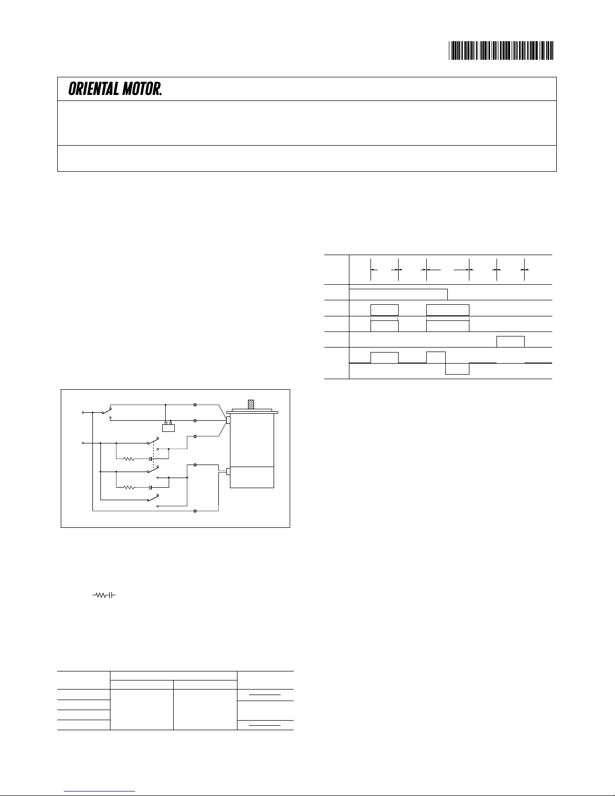
■Connecting Diagrams
●Protection of the relay contacts
The motor switch (SW2) and the electromagnetic brake switch (SW3) emit sparks
when turned on and off. In order to protect the relay contacts.
CR circuit ( ) must be connected.
Co=0.1〜0.2μF 250WV:4RK25GN-AM-115,
5RK40GN-AM-115
500WV:4RK25GN-CME,
5RK40GN-CME
Ro=5〜200Ω, 1/4W minimum
●Switch Specifications
No. of switches
SW1
SW2
SW3
SW4
Switch specifications
Single Phase 115V
AC125V 3A
Minimum
Single Phase 220/240V
AC250V 1.5A
Minimum
Note
Move together
WHITE
Capacitor
STOP
RUN
CCW
CW
SW2*
Ro Co
SW1
GRAY
LINE
BLACK
Motor
Electromagnetic
Brake
STOP
RUN
OFF
ON
SW3*
Ro Co
YELLOW
YELLOW
SW4
※SW2 and SW3 move together.
■Timing Chart
■Operations
●Run/Stop
1. Motor will rotate when SW2 and SW3 are switched simultaneously to
RUN (short circuit) switching SW4 to OFF (open).
2. When SW2 and SW3 are switched simultaneously to STOP (open),
the motor stops immediately by electromagnetic brake and holds the
load.
3. To rotate the motor shaft by hand during the motor stops, switch
SW4 to ON (short circuit). The electromagnetic brake is released
and the motor shaft can be rotate easily by hand.
(Always switch SW4 to OFF (open) when running and stopping the
motor. SW4 is not necessary when such a operation is not needed.)
●Direction of Rotation
To rotate the motor in a clockwise (CW) direction, switch SW1 to CW.
To rotate it in a counter-clockwise (CCW) direction, switch SW1 to
CCW.
The diagram shows the direction of rotation of the motor shaft as
viewed from the motor shaft end.
SW1
SW2
SW3
SW4
Motor
CW
ONOFF
CCW
RunStop Stop Stop
Brake Release
Run
Run
CW
CCW
CW
Stop Stop Stop
Run
Run
Stop
LoadHolding
Run
Brake
Release
Stop
LoadHolding
Stop
LoadHolding
Page 2
■Gearhead Connection
Specially designed gearheads are available that can be easily coupled
directly to these motors.
Sufficient torque can be obtained while reducing the motor speed to the
required speed on the gearhead output shaft.
●Types of Gearhead
●The box(□) represents the desired gear ratio, which thereby becomes part of
the code for the gearhead.
●Gear Ratio:3, 3.6, 5, 6, 7.5, 9, 12.5, 15, 18, 25, 30, 36, 50, 60, 75, 90, 100,120,
150, 180
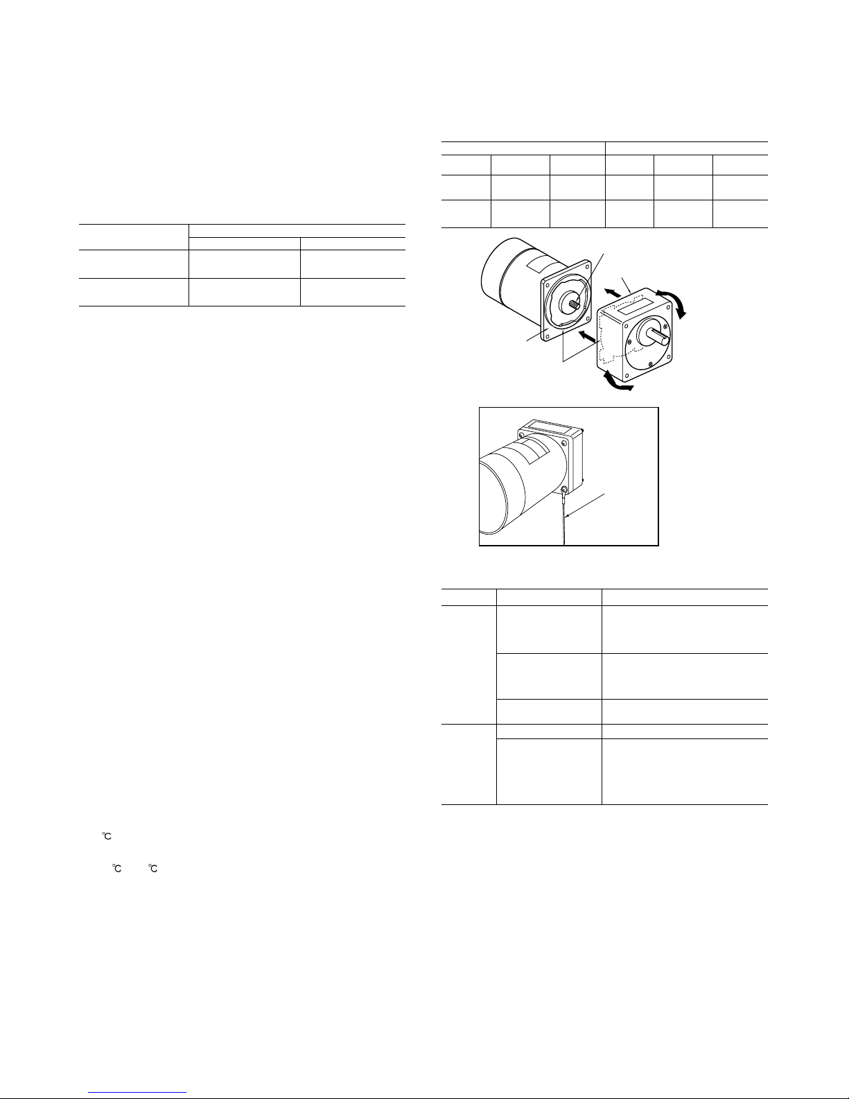
■Precautions for Connecting Gearhead to the Motor
1. Connecting Gearhead
As the figure to the right shows, motor and gearhead are put together
using the recessed areas on each unit as guides while gently turning
the gearhead back and forth for smooth engagement of gearing and
cog. Care should be taken not to damage the shaft by applying
excessively large force during attachment. Then use the mounting
screws that come with the gearhead to screw the gearhead onto the
motor until if fits snugly.
Note:Note that attempt to put motor and gearhead together by force or
entrapping of material like metal chips can result in damage to the geared
section of the shaft or the cog leading to abnormal noise and shortened
operating life. Assembly should be carried out with the necessary care.
2. Installation
Install the motor firmly to your equipment. The heat-sink effectiveness
and protection of vibration are required as much as possible. Useful
motor mountings are available separately.
3. Grounding
Any one of the mounting bolts may serve to fix the grounding wire to
the motor casing at the time of installation of the unit. If necessary,
remove all the bolt hamptom that may impede conductivity around the
bolt mounting hole.
■Precaution on Operation
●If the motor is ON continuously for a period of 30 minutes or more,
the rated temperature may be exceeded. Under no circumstances
should the temperature of the motor case be allowed to rise above
90
(194ºF).
●Use the motor in a place where the working ambient temperature is
−10
to 50 (14ºF to 122ºF) and humidity is 85% less.
●Do not use the components in a place where a corrosive gas, water,
oil, dust and/or direct sunlight may contact the components.
●Avoid places where vibration/shocks are heavy and/or constant.
The geared section of the shaft
Edge of recessed area
Recessed area
Flange surface
Ground Wire
Motor Models
4RK25GN-AM-115
4RK25GN-CME
5RK40GN-AM-115
5RK40GN-CME
Gearhead Models
Inch size output shaft
4GN□KA
(Ball bearing type)
5GN□KA
(Ball bearing type)
Metric size output shaft
4GN□K
(Ball bearing type)
5GN□K
(Ball bearing type)
Inch size shaft gearhead Metric size shaft gearhead
Models
4GN□KA
5GN□KA
Shaft Diameter
0.375" dia.
(9.525mm dia.)
0.5" dia.
(12.7mm dia.)
Shape of
Shaft
Flat cutted
Flat cutted
Models
4GN□K
5GN□K
Shaft Diameter
10mm dia.
12mm dia.
Shape of
Shaft
Key slot
(Key provided)
Key slot
(Key provided)
●Size of Gearhead output shaft
■Trouble Shooting
Symptoms
Motor does
not turn
Motor turns
wrong
direction
Causes
No voltage coming to
motor
Electromagnetic brake is
ON
Load is too large
Motor is mis-wired
Gearhead is attached
Check Point
Check that motor has no looseconnection
Check that lead wires have no
interruption
Check that the electromagnetic brake is
released
Check that the electromagnetic brake
has been energized
Remove the load and check operation of
motor alone
Check the motor connection
Check the gear ratio
When connecting gearhead to reduce
the speed, the gearhead output shaft
can be made to rotate in an opposite
direction as the motor depending on
which speed reduction ratio is chosen.
Page 3

Printed on Recycled Paper
・Characteristics, specifications and dimensions are subject to change without notice.
・Please contact your nearest ORIENTAL MOTOR office for further information.
ORIENTAL MOTOR U.S.A CORP.
Los Angeles Office Tel:(310)784-8200 Fax:(310)325-1076
San Jose Office Tel:(408)358-6900 Fax:(408)358-8200
Chicago Office Tel:(847)240-2649 Fax:(847)240-2753
Cincinnati Office Tel:(513)563-2722 Fax:(513)956-3183
Austin Office Tel:(512)918-9438 Fax:(512)335-5983
New York Office Tel:(973)359-1100 Fax:(973)359-1090
Boston Office Tel:(781)848-2426 Fax:(781)848-2617
Atlanta Office Tel:(770)716-2800 Fax:(770)719-8515
Canada Office Tel:(905)502-5333 Fax:(905)502-5444
Technical Support Line Tel:(800)468-3982
Available from 8:30 AM to 8:00 PM , Eastern Time
ORIENTAL MOTOR (EUROPA) GmbH
Headquarters and Düsseldorf Office
Tel:02131-95280Fax:02131-952899
Munich Office Tel:08131-59880 Fax:08131-598888
Hamburg Office Tel:04076-910443 Fax:04076-910445
ORIENTAL MOTOR (UK) LTD.
Tel:01252-519809 Fax:01252-547086
ORIENTAL MOTOR (FRANCE) SARL
Tel:01 47 86 97 50 Fax:01 47 82 45 16
ORIENTAL MOTOR ITALIA s. r. l
Tel:02-3390541 Fax:02-33910033
TAIWAN ORIENTAL MOTOR CO.,LTD.
Tel:(02)2299-9360 Fax:(02)2299-4173
SINGAPORE ORIENTAL MOTOR PTE LTD.
Tel:(745)7344 Fax:(745)9405
ORIENTAL MOTOR .KOREA CO.,LTD.
Tel:(02)632-9122 Fax:(02)679-4588
ORIENTAL MOTOR CO.,LTD.
Headquarters
Tel:(03)3835-0684 Fax:(03)3835-1890
 Loading...