

Oriel Instruments MS257-M-MC-A, MS257-M-FH-D, MS257-M-FH-A, MS257-M-FH-L, MS257-M-MC-D User Manual
...Page 1
MS257 USB/RS232
MONOCHROMATOR
AND
SPECTROGRAPH
User's
MODELS:
MS257-M-MC-L, MS257-M-MC-D, MS257-M-MT-A, MS257-M-MT-L, MS257-MMT-D, MS257-S-FH-A, MS257-S-FH-L, MS257-S-FH-D, MS257-S-MC-A, MS257S-MC-L, MS257-S-MC-D, MS257-S-MT-A, MS257-S-MT-L, MS257-S-MT-D
MS257-M-FH-A, MS257-M-FH-L, MS257-M-FH-D, MS257-M-MC-A,
Family of Brands – Corion
M77781A, Rev B
Manual
®
• New Focus™ • Oriel® Instruments • Richardson Gratings™ • Spectra-Physics
®
Page 2

- 2 -
TABLE OF
CONTENTS
1 SAFETY OPERATING
2
INTRODUCTION .................................................................................................................................... 5
3 SETUP AND MOUNTING
3.1 MOUNTING MS257 TO A FLAT
3.2 MOUNTING OTHER INSTRUMENTS TO THE
3.3 TURRET
4 QUICK
5 INSTRUMENT DESCRIPTION
6 CONFIGURATION
7 INSTRUMENT
8 PROGRAMMING MS257
9
ACCESSORIES .................................................................................................................................... 44
10
SPECIFICATIONS................................................................................................................................ 57
11 APPENDIX A - BASIC GRATING
12 DECLARATION OF
13 WARRANTY AND
START........................................................................................................................................ 9
4.1 WORKING WITH THE HAND
4.2 WORKING WITH A COMPUTER
5.1 LAYOUT AND MAJOR FEATURES
6.1 USE AS A
6.2 USE AS A SPECTROGRAPH
6.3 USE AS AN IMAGING
6.4 INSTRUMENT FEATURES
OPERATION ................................................................................................................ 14
7.1 INSTRUMENT
7.2 UTILITY AND CONFIGURATION SOFTWARE
7.2.1 MS257 UTILITY
7.2.2 UTILITY SOFTWARE
7.2.3 MS257 CONFIGURATION
7.3 77709 HAND CONTROLLER
7.4
COMMUNICATIONS.............................................................................................................
9.1 GRATING
9.2 CONFIGURING THE MS257 FOR TURRET
9.3
GRATINGS............................................................................................................................
9.4 SLITS
9.5 FILTER
9.6 INPUT AND OUTPUT
13.1 CONTACTING ORIEL
13.2 REQUEST FOR ASSISTANCE / SERVICE
13.3 REPAIR
13.4 NON-WARRANTY
13.5 WARRANTY REPAIR
13.6 LOANER / DEMO
....................................................................................................................................
PRECAUTIONS ................................................................................................ 4
...................................................................................................................... 6
SURFACE...........................................................................
MS257 .........................................................
INSTALLATION .......................................................................................................
CONTROLLER .......................................................................
...........................................................................................
............................................................................................................ 10
.....................................................................................
VERSATILITY ....................................................................................................... 11
MONOCHROMATOR..........................................................................................
..............................................................................................
SPECTROGRAPH ...........................................................................
..................................................................................................
CONFIGURATION .......................................................................................
...................................................................
SOFTWARE ...............................................................................
INSTALLATION .................................................................
SOFTWARE ............................................................
...............................................................................................
..................................................................................................................... 43
TURRETS ............................................................................................................
INSTALLATION .............................................
WHEELS ..................................................................................................................
PORTS..............................................................................................
INFORMATION .............................................................................. 60
CONFORMITY..................................................................................................... 67
RETURNS .............................................................................................................. 68
INSTRUMENTS................................................................................
.........................................................................
SERVICE ................................................................................................................
REPAIR ..................................................................................................
...........................................................................................................
MATERIAL...............................................................................................
6
7
8
9
9
10
11
12
12
13
14
16
16
17
25
33
42
44
44
45
46
53
54
68
69
69
70
70
71
Page 3

- 3 -
LIST OF FIGURES
Figure 1: Grating Care and
Figure 2: MS257
Dimensions......................................................................................................................6
Figure 3: Input and Output
Figure 4: Mounting Hole Pattern for Ports
Figure 5: Monochromator Interior
Figure 6: Light Path of a Monochromator
Figure 7: Light Path of a
Figure 8: Light Path of Imaging
Figure 9: Utility Program Main
Figure 10: Configuration Program main
Figure 11: Hand Controller Keypad
Figure 12: Rear Panel
Figure 13: Quadruple Grating
Figure 14: Using Fixed Slits with MS257
Figure 15: Micrometer Driven Slit
Figure 16: Micrometer Driven Slit
Handling ..........................................................................................................4
Ports .................................................................................................................7
..................................................................................................7
Layout..................................................................................................10
.................................................................................................11
Spectrograph .....................................................................................................12
Spectrograph ..........................................................................................12
Window.....................................................................................................24
window ........................................................................................32
..........................................................................................................36
Connections ..........................................................................................................42
Turret.........................................................................................................44
..................................................................................................47
Dimensions...........................................................................................49
Adjustments.........................................................................................50
Figure 17: Micrometer Driven Slit Closed Position
Figure 18: Motorized Slit
Figure 19: Filter
Installation ........................................................................................................................53
Figure 20: Motorized Flip
Figure 21: Dual Source
............................................................................................................................51
Mirror .................................................................................................................55
Configuration........................................................................................................56
Figure 22: Diffraction Geometry of a Plane Reflection
Figure 23: The "Grating
Figure 24: Grating
Figure 25: Diffraction
Figure 26: Polarization and
Equation" .............................................................................................................61
Resolution ....................................................................................................................63
Orders ......................................................................................................................64
Efficiency........................................................................................................66
...................................................................................50
Grating..................................................................60
Page 4
- 4 -
M77781A
MS257™ USB/RS232
MONOCHROMATOR AND SPECTROGRAPH
1 SAFETY OPERATING PRECAUTIONS
Electrical
The MS257 operates from nominal ac mains of 115/230 Vac. Do not attempt to work in the electrical
compartment without first disconnecting the power cord, since you may contact high voltage areas inside
the compartment.
The MS257 has an internal microprocessor and should be installed with appropriate surge/EMI/RFI
protection on all power lines. Dedicated power lines or line isolation may be required for some extremely
noisy sites.
The circuits used in MS257 are extremely sensitive to static electricity and radiated electromagnetic fields
and therefore MS257 should not be used nor stored in close proximity to EMI/RFI generators,
electromagnetic/electrostatic field generators, radioactive devices, or other similar sources of high energy
fields. Some examples of equipment, which can cause problems, are plasma sources, arc welders, radio
frequency generators, x-ray instruments, and pulsed/ triggered gas discharge optical sources. Operation
of the MS257 close to intense pulsed sources (lasers, xenon strobes or arc lamps, and the like) may
compromise performance if shielding is inadequate, and may cause permanent damage to the
microprocessor. Do not place any containers containing liquids on top of the instrument. There is a
danger that liquid may enter the ventilation holes in the electronics compartment and cause a short
circuit. This may cause the instrument to fail.
Mechanical
Avoid dropping, sudden shocks, or rough handling of the monochromator since this may cause the
system to lose its calibration and may destroy the high precision drive components or optics.
Do not use more than finger force in tightening down the grating mounts, since this may cause damage to
the drive assembly
Optical
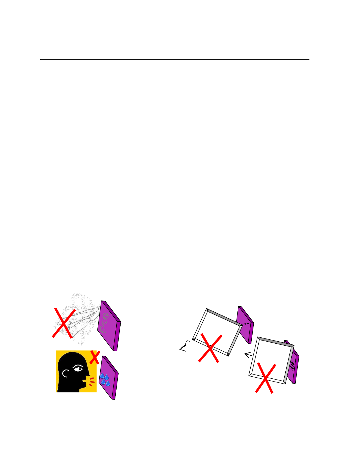
Wear powder-free gloves. Do not wear finger cots – hands should be completely covered. Do not touch
any optical surfaces - even if wearing gloves - since this is likely to cause irreparable damage. Do not
attempt to clean an y optical surface except by blowing off dust or lint particles with a stream of dry clean
air or nitrogen. Do not allow condensation from talking or breathing to form on the grating. Gratings can
be scratched easily! Be very careful when removing the plastic grating covers. A cover for a grating must
never touch the grating’s front surface. The cover should only touch the edges of the grating. Customers
should keep the covers on hand to protect gratings during storage or transportation.
Figure 1: Grating Care and Handling
Page 5

M77781A
MS257™ USB/RS232
MONOCHROMATOR AND SPECTROGRAPH
5
2 INTRODUCTION
The MS257 isn't just another monochromator. It is the heart of a completely automated spectral data
acquisition system. All you need is a PC and a detector system.
The MS257 is an F/3.9 instrument with a focal length of 257 mm for use as a monochromator, true flat
field spectrograph or imaging spectrograph. It incorporates the latest advances in optical design, high
speed wavelength drives, and total system automation.
The MS257 has been designed with a flat exit image plane and an oversized focusing mirror to serve as a
true flat field spectrograph. Adapter flanges are available for lnstaSpec™ diode arrays and CCD
detectors, as well as detectors made by other manufacturers.
The imaging version of MS257 has special corrected optics (toroidal mirrors) which correct the final image
for astigmatism and enable point to point spectral imaging of the input source or sources. The optics have
been designed to work with CCD detectors which are used to record simultaneous spectra from multiple
sources.
Key Features:
1, 2, 3, or 4 grating turret with automatic grating switching
Rapid high torque motor drive
Rigid housing for optical stability with sealed seams for light tightness
2 detector ports with automatic detector switching
Motorized slits for automatic bandpass selection
Advanced optical design results in negligible stray light
Tilted focal plane for eliminating re-entrant spectra from detectors
Corrected optics for spectral imaging (version 77782)
Fine focus adjustment for diode arrays and CCDs
Internal shutter for dark scans
Automated auxiliary input port option
Separate electronics compartment for exceptional temperature stability
On board microprocessor for automated control
Complete computer control via USB or RS232
Page 6

M77781A
MS257™ USB/RS232
MONOCHROMATOR AND SPECTROGRAPH
6
3 SETUP AND MOUNTING
After unpacking, mount the MS257 in a convenient location, install the grating turret with gratings and
remove the covers from optics. After these steps have been completed, plug in the power cord.
*** WARNING
DO NOT PLUG IN THE POWER
UNTIL ALL THE SAFETY PRECAUTIONS HAVE BEEN
***
CORD
READ.
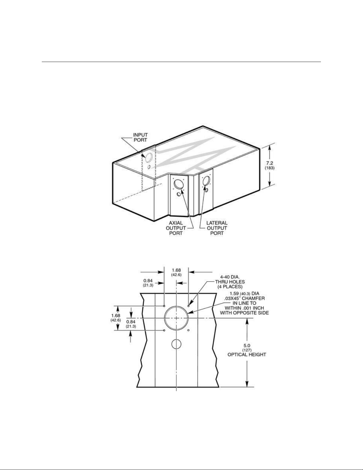
3.1 MOUNTING MS257 TO A FLAT SURFACE
There are three 1/4-20 tapped holes under the housing, these can be used to screw in the
supplied adjustable feet or to mount to other objects. Please refer to Figure 2.
Figure 2: MS257
Dimensi ons
Page 7
M77781A
MS257™ USB/RS232
MONOCHROMATOR AND SPECTROGRAPH
7
3.2 MOUNTING OTHER INSTRUMENTS TO THE MS257
Sources, detectors and other instruments that have an Oriel 1.5 inch (47 mm) female flange can
be easily attached to any of the MS257 slit ass emblies at the ports. Other accessories can also
be mounted directly to MS257 at any of the input or output ports (Figure 4).
Figure 3: Input and Output
Ports
Figure 4: Mounting Hole Pattern for
Ports
Page 8

M77781A
MS257™ USB/RS232
MONOCHROMATOR AND SPECTROGRAPH
8
3.3 TURRET INSTALLATION
In order to protect the most sensitive part of the instrument during transportation, the grating
turret is packaged separately from the housing.
Install the turret into the instrument using the following procedure:
Quadruple Grating Turret (may have 2, 3 or 4 gratings installed)
Put gloves on to avoid fingerprinting the gratings.
Remove the MS257 cover.
Leave the protective cover on the gratings.
Make sure the grating turret cable is hanging freely at the side of the turret.
Locate the grating turret on the drive platform by aligning the two captive bolts with their
holes, and the center with the platform boss.
Adjust the position of the turret until it locates on the alignment pin and sits flush with the
platform.
Connect the turret cable.
Tighten the two mounting bolts by hand. Do not over tighten!
Remove the bottom and side protective grating covers, and lastly the upper grating cover.
For the bottom grating, let the plastic cover drop straight down and remove it horizontally
without touching or scraping the bottom grating surface.
Be very careful not to touch the gratings.
Replace the MS257 cover, using all cover screws.
Single Grating Turret
Remove the MS257 cover.
Leave the protective cover on the grating until the mount is screwed down.
Locate the grating mount and twist clockwise to correctly align it.
Tighten the mounting bolt by hand. Do not over tighten!
Remove the protective grating cover.
Be very careful not to touch the grating.
Replace the MS257 cover, using all cover screws.
Page 9

M77781A
MS257™ USB/RS232
MONOCHROMATOR AND SPECTROGRAPH
9
4 QUICK START
4.1 WORKING WITH THE HAND CONTROLLER
The Hand Controller (Model 77709) controls the MS257 via an RJ11 jack located on the back
panel. Below the LCD screen are five LEDs that indicate the status of various functions. To
operate the MS257 with the hand controller, ensure that the following two LEDs are ON.
Power LED: The MS257 is powered up and the Hand Controller is connected and working
properly.
Local LED: When the Hand Controller has control of the MS257. To activate the LED, press
the "Local" button. The LCD screen will turn on and indicate the current status of the
instrument.
For further instructions on how to operate the instrument using the Hand Controller, please refer
to Section 7.3 of this manual.
4.2 WORKING WITH A COMPUTER
Connect the MS257 to the computer via the provided USB or RS232 cable, or an IEEE to
RS232 adapter (Model 77793).
Use the utility software (details are provided in Section 7.2) to control the instrument.
Page 10
M77781A
MS257™ USB/RS232
MONOCHROMATOR AND SPECTROGRAPH
10
5 INSTRUMENT DESCRIPTION
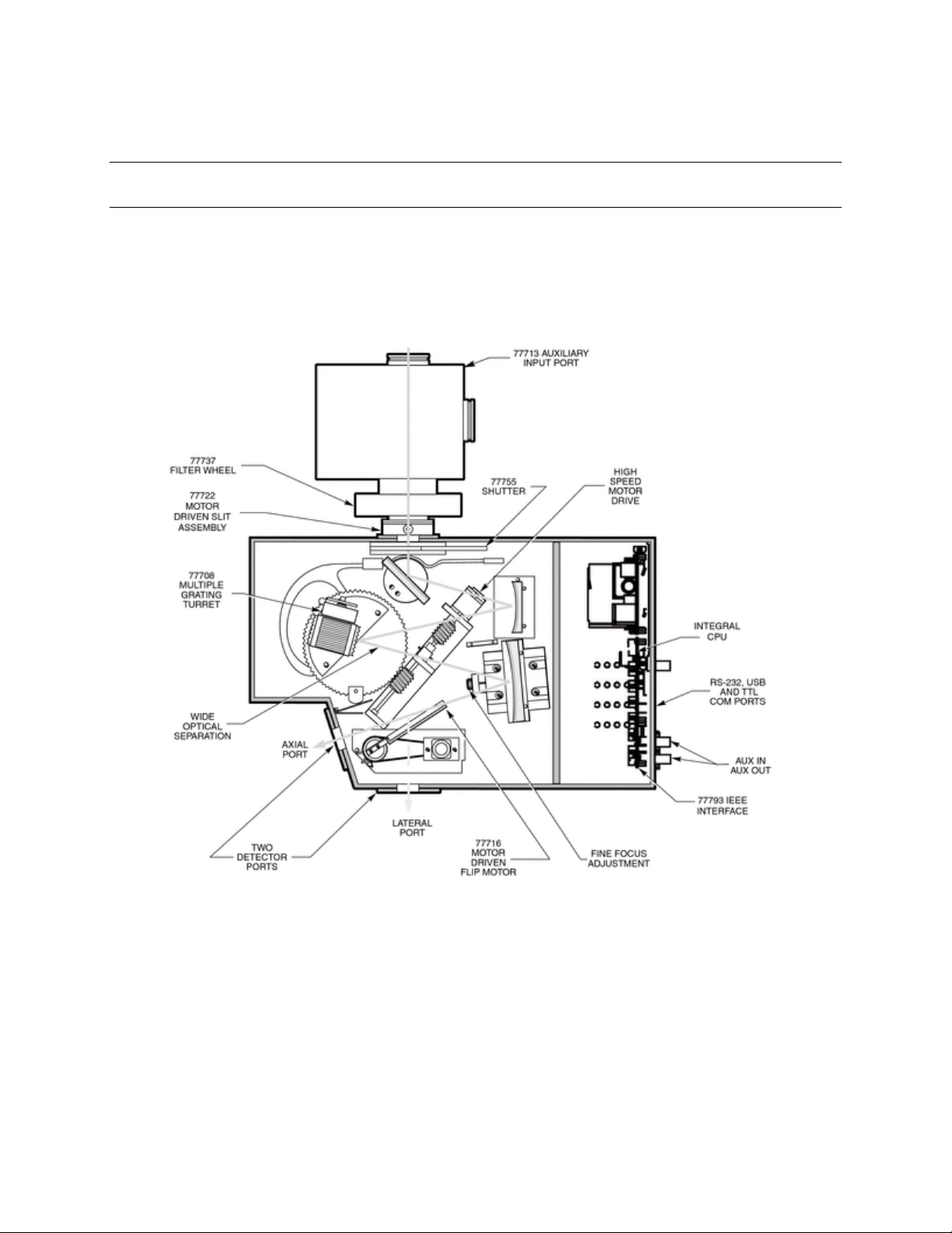
5.1 LAYOUT AND MAJOR FEATURES
Refer to the descriptions of the MS257 accessories throughout this manual for more information
on the items shown in Figure 5.
Figure 5: Monochromator Interior Layout
Page 11
M77781A
MS257™ USB/RS232
MONOCHROMATOR AND SPECTROGRAPH
11
6 CONFIGURATION VERSATILITY
6.1 USE AS A MONOCHROMATOR
Figure 6 depicts the MS257 in use as a monochromator. The "in-line" configuration uses a turning
mirror at the exit port. This can be either the 77718 Replaceable Turning Mirror on the 77716
Motorized Output Flip Mirr or. When the mirror is not in position, the axial port is selected as the
exit port.
Figure 6: Light Path of a Monochromator
Page 12

M77781A
MS257™ USB/RS232
MONOCHROMATOR AND SPECTROGRAPH
12
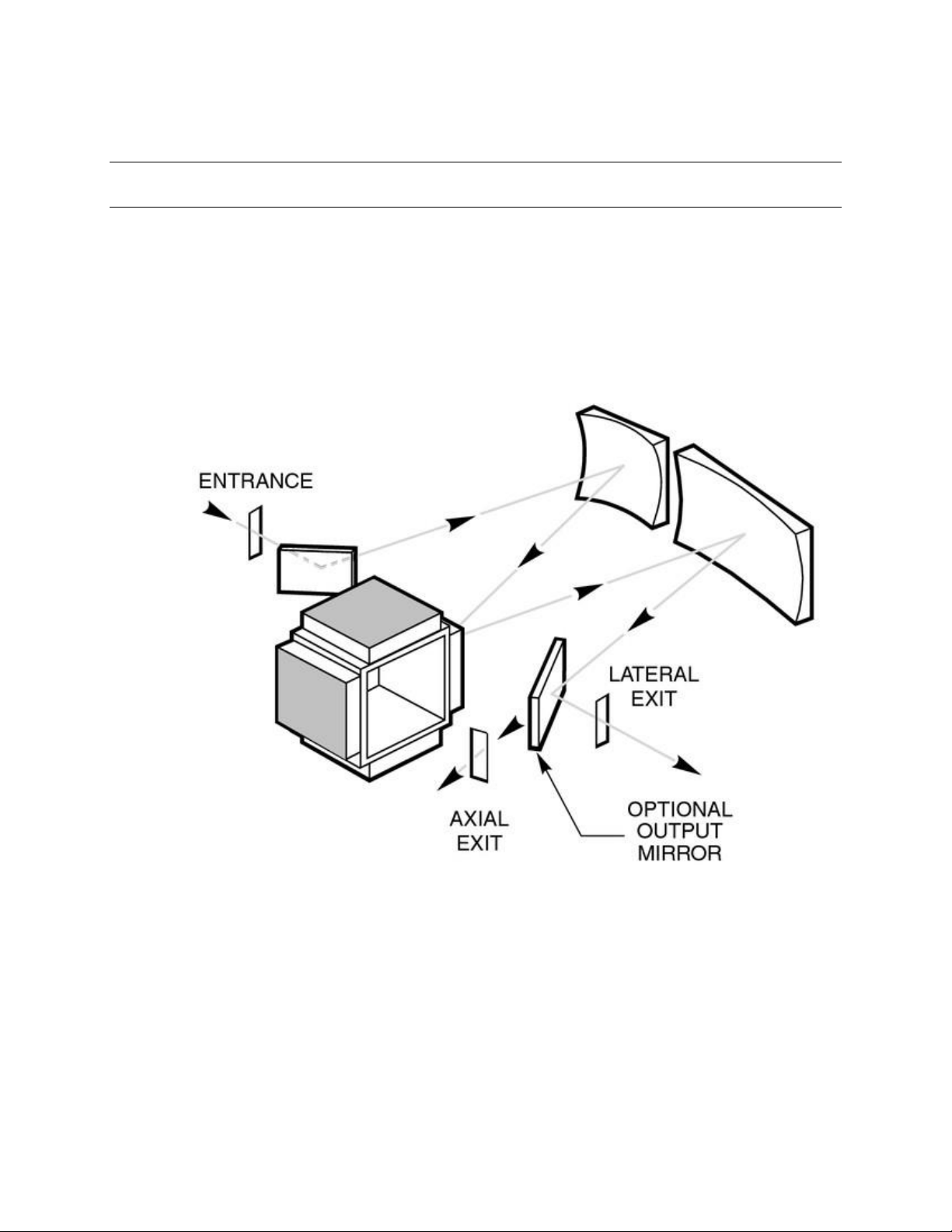
6.2 USE AS A SPECTROGRAPH
Figure 7 depicts the MS257 in use as a spectrograp h. The axial port accommodates detectors
over 4” (100 mm) diameter depending on the distance they need to be mounted from the port
face. This port can readil y accommodate lnstaSpec™ detectors as well as several other
manufacturers. Note that the spectrum at the lateral output port is reversed from that of the axial
output port.
Figure 7: Light Path of a
6.3 USE AS AN IMAGING SPECTROGRAPH
Figure 8 depicts the MS257 in use as an imaging spectrograph. This is similar to the conventional
spectrograph except that the sources are spatially imaged at the exit plane so that there is a
separate spectrum for each input source.
Spectrograph
Figure 8: Light Path of Imaging
Spectrograph
Page 13

M77781A
MS257™ USB/RS232
MONOCHROMATOR AND SPECTROGRAPH
13
6.4 INSTRUMENT FEATURES
Flexible Instrument Control
The MS257 can be is controlled by using the Hand Controller, a terminal program to send MS257
BASIC language commands or a stand alone computer program. See the relevant sections for
details of these methods of operation.
Negligible Stray Light
Great attention has been paid to eliminating stray light. The wide open optical layout and
exaggerated tilt of the exit focal plane ensure this. While other designs may be more compact it is
inevitable that they'll suffer from’re-entrant' spectra at certain grating angles. It is important that
diffracted light not be allowed to reflect from the mirrors, or from the face of a focal plane detector
such as a diode array or CCD, back onto the grating. This light can then be re-diffracted and
cause ghost images or stray light at the detector. The MS257 was designed to remove this
possibility for CCD detectors - even as large as 28 mm x 28 mm.
Calibrated Motor Drive
The MS257 uses an ultra-rapid stepper motor drive, with an oversize worm gear to ensure high
precision and stability. This computer controlled worm drive is superior to most sine drive
mechanisms. It allows separate calibration factors to acc ommodate for differences between
gratings with nominally the same lines per millimeters (for example, 1200 I/mm blazed ruled
grating and a holographic grating). Scans are automatically linearized so that the wavelength
intervals are equal, no matter which units are chosen: nanometers, microns or wavenumber.
In an ideal world the wavelength should be able to be calculated directly from the step position
(grating angle). However, gears are not perfect. They are slightly non-concentric and have
surface finish flaws, which result in a significant deviation in real position angle (and therefore
wavelength) from theoretical. This is corrected by mapping the entire drive, and charting the
divergence of real from theoretical drive angle. Mathematical curve fitting is then used to correct
the step position and provide real wavelength. The MS257 is spectrally mapped at the factory
with a system default calibration for the grating drive. Remapping of the drive should never be
attempted by unauthorized personnel. If remapping is necessary, the entire MS257 must be
returned to the factory.
lntegrated Shutter
There are two internal shutters available for the MS257. Both shutters are normally closed. They
can be controlled through the MS257 command language or via an externally applied TTL signal.
The 77755 shutter has stray light rejection better than 0.001% for dark scans and dark current
measurements. The shutter may be changed in the field so that it is normally open. Contact the
Oriel Instruments service department for details. The 77755 shutter automatically closes when
changing gratings and filters in order to protect the detector from possible high light intensities at
various grating angles - particularly the zero order white light. This safety feature may be turned
off by setting the shutter to the manual mode. The 77717 fast shutter is available for pulsed work.
Exposure times can be as short a 5 ms, with repetition rates as fast as 40 Hz. A synchronizing
output signal is available from the fast shutter for very precise timing of external events. The
77717 fast shutter does not automatically react to grating changes.
Page 14

M77781A
MS257™ USB/RS232
MONOCHROMATOR AND SPECTROGRAPH
14
7 INSTRUMENT OPERATION
7.1 INSTRUMENT CONFIGURATION
The instrument configuration is maintained as a collection of parameters and values. Suitable
factory defaults are provided. The Active Configuration is the current setup. This is always
saved and restored when powering up the instrument.
Configurations can be saved and loaded in several ways:
To save the active user configuration and to reload the user configuration, one may use
Hand Controller, the configuration software or a computer terminal program.
The instrument can be configured by Oriel Instruments to have calibrations saved on CD for more
than one grating turret, allowing the user to change the turret and load the appropriate
configuration information as needed.
Individual Grating Calibration
Each grating is precisely aligned on its mount or grating turret. However, small offsets or
calibration adjustments may be required for each grating. This calibration should be performed for
each port in use. The procedure is as follows:
1. Select a grating.
2. Select a source with prominent spectral lines for calibration purposes.
3. Use very small slit sizes. I using a diode array or CCD, use a small entrance slit.
4. Drive the grating to a spectral line such as a HeNe line at 632.8 nm or an Hg line at 546 nm.
5. Step the motor drive using the Hand Controller or MS257 programming language until the line
is centered at the output slit, or in the case of a diode array or CCD at the center pixel.
6. Use the Calib command on the Hand Controller or CALWAV command if using the terminal
program, and enter the correct wavelength for the spectral line.
7. The recalibration of the grating for that port is now complete.
8. Change the detector port using the Hand Controller or MS257 programming language if the
MS257 is equipped with an Output Flip Mirror. Never move the flip mirror manually.
9. Repeat the procedure for the other detector port if it is being used.
10. Repeat Step 1 through 9 for each grating on the turret.
Fine Focus Adjustment
In order to obtain the best optical performance, a fine focus adjustment feature is included. This
enables precise translation of the exit mirror to optimize the image onto focal plane detectors
such as diode arrays and CCDs. These accessories do not have a precisely known detector
positions, which is why the light may have to be focused to achieve best resolution. Note that
after refocusing, one may require a new spectral calibration.
the
Page 15

M77781A
MS257™ USB/RS232
MONOCHROMATOR AND SPECTROGRAPH
15
Minimizing Stray Light
Stray light is unwanted light which interferes with the light being measured or transmitted. This
results in additional noise to light measurements. At best, this results in incorrect measurements.
At worst, the signal cannot be measured. Stray light can occur for a number of reasons:
Incorrect setup
The most significant sources of stray light are light leakage. Light could enter the MS257 through
misplaced covers, as well as slit holders and detectors without adequate sealing. Make sure that
all covers, detectors and flanges are well seated and screwed down.
Overfilling
lf the F number of the source is lower than the F number of the monochromator this produces
what is referred to as overfilling. The light will spill over the sides of the entrance mirror and will
reflect around the housing resulting in stray light. The MS257 is designed to prevent overfilling.
But even so, the light has already entered the housing and must be absorbed by the baffles. It is
better to match the source F number to the monochromator's F number and prevent overfilling.
Reflections from walls
Light is dispersed by the grating; the selected wavelengths strike the exit mirror and are imaged
at the exit focal plane. Other wavelengths, zero order 'white' light, and other orders of the
diffracted light strike interior walls and must be absorbed before they bounce around and emerge
at the exit as stray light at the detector. The MS257 makes use of light traps and baffles as well
as black paint in order to minimize the amount of light which can eventually find its way to the
detector.
Gratings
Gratings are not perfect reflectors, so a certain amount of incident light is scattered and
contributes to stray light. In fact, gratings are a major source of stray light since they are within
the optical path. Imperfect rulings or ion etched blazed lines contribute to stray light. Often the
major source of stray light is dust - and sometimes even fingerprints. Keep the gratings clean by
minimizing dust and occasionally blowing them clean with dry clean air or nitrogen.
Mirrors
Mirrors gradually accumulate dust, and can have imperfections. These surfaces scale light and
add to stray light. If the bevels of the mirrors are not adequately masked, these also add to the
scatter. Often, the major source of stray light is dust - and sometimes even fingerprints. Keep the
mirrors clean by minimizing dust and occasionally blowing them clean with dry clean air or
nitrogen.
Detectors
The detector has never been considered a source of stray light, since with monochromators there
is a very small exit slit through which light would have to reenter once it has reflected off the
detector surface. Spectrographs however have wide flat focal plane detectors which readily
reflect light. The shiny surface of a silicon diode array can reflect as much as 20% of the light back
into the spectrograph. The stray light can be extremely significant in certain areas of the spectrum,
particularly if light from relatively high intensity wavelengths are finally reimaged onto areas of the
detector which are recording low intensity wavelengths. The MS257 has the focal plane angled in
such a way as to direct light reflected from the detector away from the mirrors and grating and into
'safe' baffles.
Page 16
M77781A
MS257™ USB/RS232
MONOCHROMATOR AND SPECTROGRAPH
16
7.2 UTILITY AND CONFIGURATION SOFTWARE
The Monochromator Utility Software CD contains:
Installation setup for Mono Utility software.
The utility application provides easy access to almost all MS257 functions.
A folder with the MS257 configuration application installation setup.
The Factory.cfg file, which is a unique file for each instrument with configuration parameters
recorded. If multiple grating turrets have been calibrated, there will be a file for each one.
7.2.1 MS257 UTILITY SOFTWARE
Program Description
This program is written in National Instrument's LabView and is based on a collection of MS257
VIs. The Utility Program diagram may serve as an example or starting point for further
development in LabView. If someone is a LabView programmer and owns a full LabView
development suite, that person can load the Utility Program source code along with MS257 VIs
from the CD. One can also use the dll file included with the Utility Software to create a unique
application in any number of programming languages.
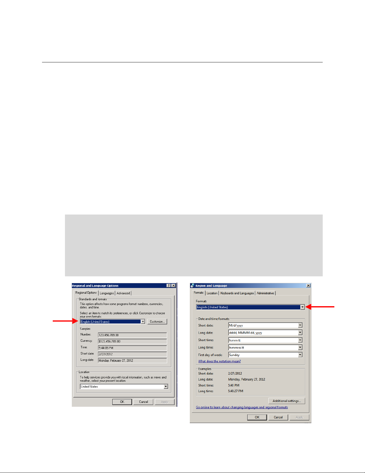
<< IMPORTANT NOTE >>
For the software to send the proper numeric format to the instrument, the Windows must be set
to English (United States). This setting is changed through the Windows Control Panel.
In Windows XP, use the Regional and Language Options setting. The format can be changed
under the Regional Options tab.
In Windows 7, use the Region and Language setting. The format can be changed under the
Formats tab.
Page 17
M77781A
MS257™ USB/RS232
MONOCHROMATOR AND SPECTROGRAPH
17
7.2.2 UTILITY SOFTWARE INSTALLATION
The MS257 utility program may be installed on computers with Windows XP or Windows 7 32-bit
operating systems. It is suggested to exit all programs before running the installer.
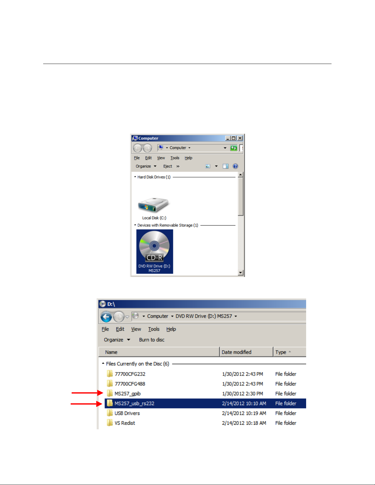
Place the installation CD into the computer which will be used to control the MS257. Open the
CD to view the contents in Computer (or My Computer if using Windows XP).
Open the MS257 folder, based upon the communication method being used.
Page 18
M77781A
MS257™ USB/RS232
MONOCHROMATOR AND SPECTROGRAPH
18
NOTE: If one is planning to use GPIB, the 77793 converter will be required to operate the
instrument. The 77793 must be set to G Mode.
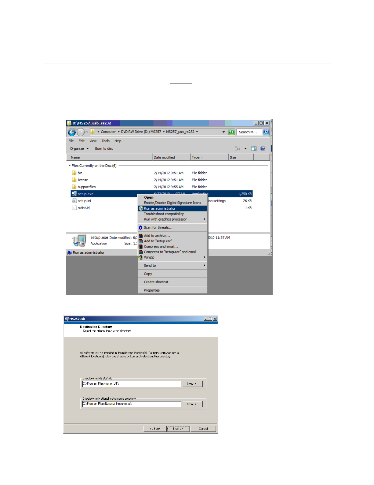
In the MS257 folder, run the setup.exe application.
If using Windows 7, right click on the application and choose “Run as administrator.
In Windows XP, double click to run the application.
Click Next.
Page 19
M77781A
MS257™ USB/RS232
MONOCHROMATOR AND SPECTROGRAPH
19
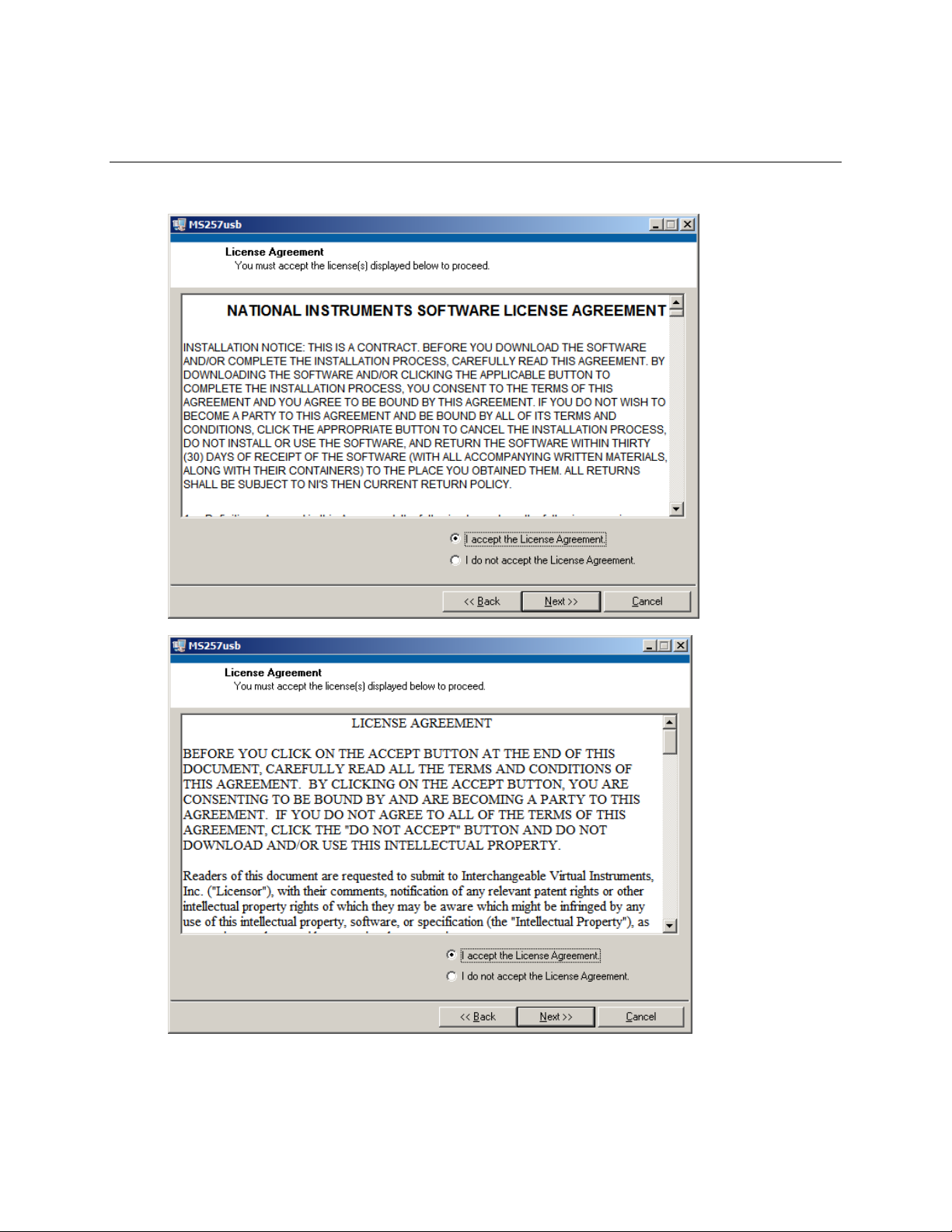
Choose to accept the two License Agreements and click Next to proceed.
Page 20

M77781A
MS257™ USB/RS232
MONOCHROMATOR AND SPECTROGRAPH
20
Click the Next button to begin the installation.
When complete, click Next for USB and RS232 installation.
For the GPIB installation, click Finish.
Page 21
M77781A
MS257™ USB/RS232
MONOCHROMATOR AND SPECTROGRAPH
21
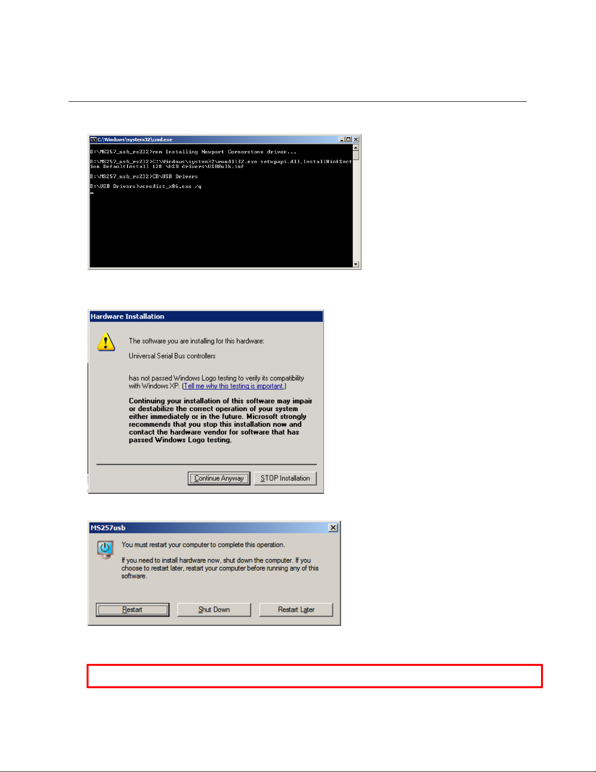
The following window will appear briefly only if installing the USB/RS232 utility program.
If installing onto a Windows XP computer, the following message may appear. Click Continue
Anyway.
Restart the computer.
If using Windows XP, the utility program installation is now complete.
If using Windows 7, additional steps are required. Details are provided on the following pages.
Page 22
M77781A
MS257™ USB/RS232
MONOCHROMATOR AND SPECTROGRAPH
22
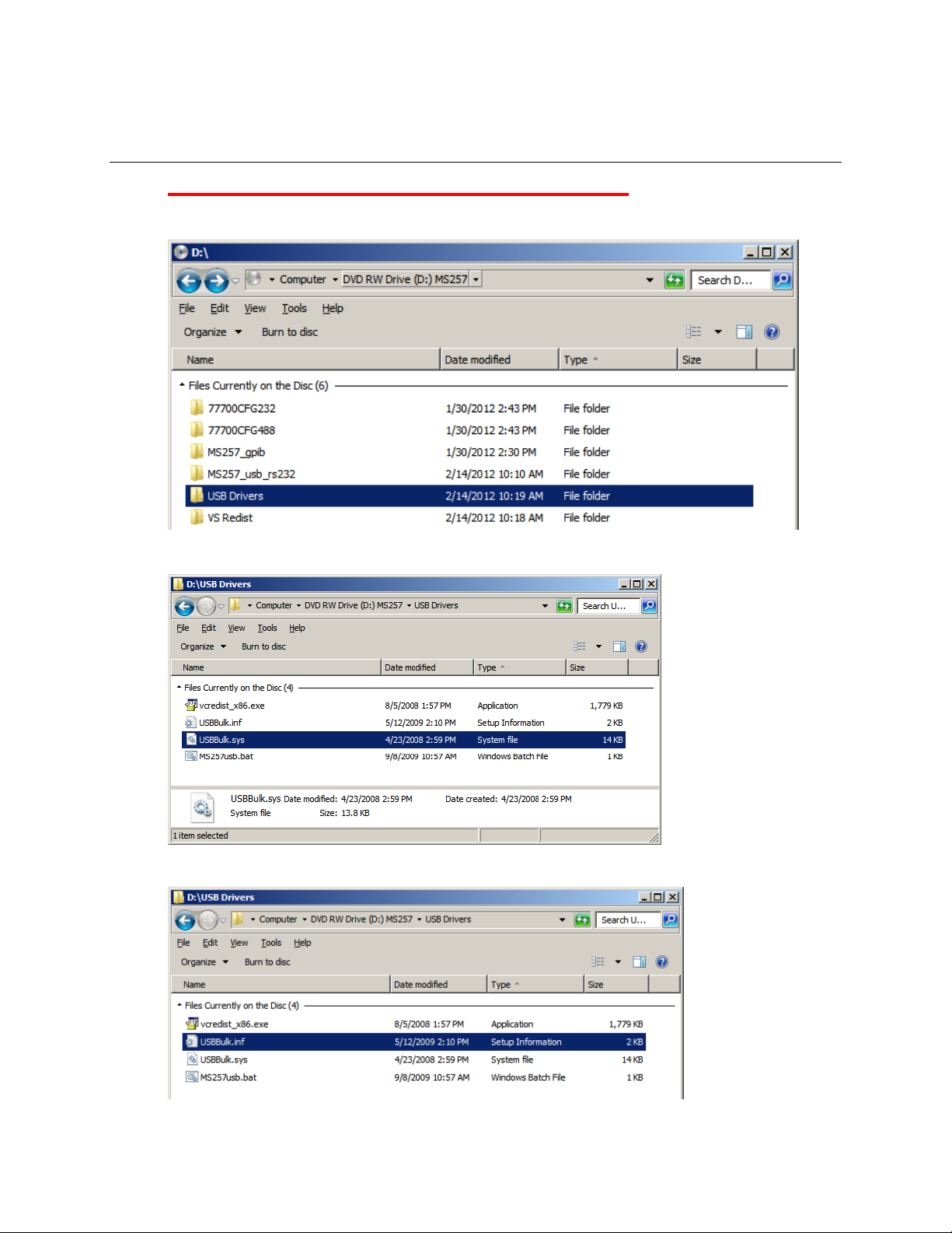
ADDITIONAL INSTRUCTIONS FOR WINDOWS 7, 32-BIT USERS
On the CD, open the USB Drivers folder.
Copy the file USBBulk.sys to the computer’s
Copy the USBBulk.info file to the computer’s Windows\Inf folder
Windows\system32\drivers
folder.
Page 23

M77781A
MS257™ USB/RS232
MONOCHROMATOR AND SPECTROGRAPH
23
Open the Program Files\Mono_UT folder on the computer. Then open the folder which contains
the utility program, based upon the communications method being used.
Right click on the .exe application and select “Properties”.
Click on the “Compatibility” tab Check the box “Run this program as an administrator” and click
OK.
Page 24

M77781A
MS257™ USB/RS232
MONOCHROMATOR AND SPECTROGRAPH
24
Using the Utility Software
Launch the application from Start/Programs/MonosUtility.
Enter the SERIAL port number if you are trying to communicate to MS257 from the RS232
host. The default port number is set to 1. If unsure of the port, check the Device Manager.
Control or view the instrument settings by invoking specific (Grating, Filter, Port, Shutter,
Units) dialog windows using push buttons on main window.
To move the instrument to a prescribed wavelength, simply enter a value in the 'Wavelength'
edit box, then click on 'GoTo'.
Fine motion control is achieved by clicking either the '>>' button to move forward or the '<<'
button to move backward.
'Calibrate' menu item can be used to induce wavelength offset in the MS257 memory.
'Setup' dialog displays gratings parameters and filters labels. To edit filter labels, select
number (1,..5). Please do not change the gratings parameters unless the intent is to override
factory configuration parameters of the instrument.
The Scan Parameters area in the main window can be used to set up a scan, which would
then be activated by 'Go Scan' button.
Figure 9: Utility Program Main
Window
Page 25

M77781A
MS257™ USB/RS232
MONOCHROMATOR AND SPECTROGRAPH
25
7.2.3 MS257 CONFIGURATION SOFTWARE
Program Description
The stand-alone Configuration program is included for setup and configuration of MS257 and its
accessories. The software was developed using National Instruments Labview. The Labview
Runtime Engine is included on the installation CD to enable use of this program without requiring
the full development version of Labview.
The software enables the user to upload a variety of configuration files to the MS257 for different
setups through the RS232 port. For example, if one has two different grating turrets, each turret
would have its own configuration parameters located in a .cfg file. The .cfg files are created
during calibration at the factory and are located on the CD that came with the instrument.
In most cases, only one .cfg file is provided with the instrument. In this situation, the
Configuration Software should only be used if the MS257's memory is corrupted or erased. If the
instrument is not working properly, review the information found in the instruction manuals. It is
suggested to contact the Oriel Instruments service department before .
NOTE: This program does not allow making changes to the parameters. Changes must be
made to the configuration file (.cfg) by using a text editor or word processor software.
The computer must communicate with the instrument through the RS232 connector, not the USB
interface. One must use the RS232 port connected directly to a computer, or connected through
the 77793 GPIB adapter. USB/RS232 adapters are commercially available if the computer being
used does not have a serial port.
Installation
The MS257 configuration program may be installed on computers with Windows XP or Windows
7 32-bit operating systems. It is suggested to exit all programs before running the installer.
Place the installation CD into the computer which will be used to control the MS257. Open the
CD to view the contents in Computer (or My Computer if using Windows XP).
Page 26

M77781A
MS257™ USB/RS232
MONOCHROMATOR AND SPECTROGRAPH
26
Open the 77700CFG folder, based upon the communication method being used.
NOTE: If one is planning to use GPIB, the 77793 converter will be required to operate the
instrument. The 77793 must be set to G Mode.
In the MS257 folder, run the setup.exe application.
If using Windows 7, right click on the application and choose “Run as administrator.
In Windows XP, double click to run the application.
Page 27

M77781A
MS257™ USB/RS232
MONOCHROMATOR AND SPECTROGRAPH
27
Click Next to continue.
If the GPIB software is being installed, fill in the Name and Company fields and click Next to
continue. Both fields must be filled in before proceeding.
Page 28

M77781A
MS257™ USB/RS232
MONOCHROMATOR AND SPECTROGRAPH
28
Browse to choose an installation location on the computer, if desired. The default location of the
Configuration program will be Program Files\OrielInstruments\77700cfg…
Click Next to proceed.
Rename the program folder, if desired, and click Next.
Page 29

M77781A
MS257™ USB/RS232
MONOCHROMATOR AND SPECTROGRAPH
29
Click Next to proceed.
When the setup has been completed, check the box to launch the program file. Then click Finish.
Page 30

M77781A
MS257™ USB/RS232
MONOCHROMATOR AND SPECTROGRAPH
30
The following window will appear briefly.
Click Next to proceed with installing the Labview Runtime Engine. Do not cancel this setup, even
if a different version had already been installed onto this computer in the past.
If the GPIB version of the software is being installed, fill in the Name and Company fields before
clicking Next. These fields are required to continue with the installation.
Page 31

M77781A
MS257™ USB/RS232
MONOCHROMATOR AND SPECTROGRAPH
31
Select Yes to accept the license agreement.
Click Next to install the Labview Runtime Engine into the default directory.
Page 32

M77781A
MS257™ USB/RS232
MONOCHROMATOR AND SPECTROGRAPH
32
Using the Configuration Software
Launch the configuration program from Start/Programs/77700cfg ...
Use the 'Retrieve Current Memory' menu to read MS257 memory and save to a file.
To view the retrieved memory selectively, click any one of the four buttons at the bottom of
the screen.
Compare MS257 configuration parameters with factory configuration parameters (Factory.cfg
on Newpo
Parameters'.
rt’s Monochromator
Utility
Software CD-ROM) by selecting ''Verify Config
If necessary to restore MS257 memory click the 'Restore From File' and when asked for file
name browse to Factory.cfg on Newport's Monochromator Utility Software CD-ROM.
Figure 10: Configuration Program main window
Page 33

M77781A
MS257™ USB/RS232
MONOCHROMATOR AND SPECTROGRAPH
33
7.3 77709 HAND CONTROLLER
The Hand Controller is a very compact hand held device with backlit LCD, and 40-key keypad.
Virtually every function of the MS257 can be controlled from the keypad, from simply moving to a
particular wavelength, to changing the grating and filter selections. It comes with a 14 ft (4.5 m)
cable.
MS257 Hand Controller Operation
The Hand Controller controls MS257 via an RJ11 jack on the back panel. System parameters
may be edited from the controller's front panel. The grating's position can be changed from the
hand controller and devices can be selected (filters, slits, slow shutter, output flip mirror and
grating changer).
The Hand Controller has three functional areas:
5 System Status LEDs
4 x 20 LCD screen for system information and parameter editing
5 x 8 Keypad (10 numeric, 5 editing keys, 24 command keys, 1 shift key)
The MS257 starts up in the Remote mode of operation (controlled via the USB or RS232 port). To
initiate control by the hand controller, the Local command key must be pressed. The shifted
command, Rem, returns control of MS257 to the computer.
Transferring of control of the MS257 between the Hand Controller and the computer can only be
initiated with the Hand Controller.
Configuring the MS257 Hand Controller
The Hand Controller comes preconfigured and ready for use. You may alter the configuration
using this procedure:
Apply power to the Hand Controller while holding down any of its keys.
Release the key when a version number appears in the upper left hand corner of the
LCD. The word 'CONTRAST' should then appear in this same area. The contrast can
then be adjusted using the Step> and Step< keys. Press Go Wav when the contrast is
set as desired.
The next number in the corner should be '9600' baud rate. If it is not use the Step> and
Step< to find '9600' and press Go Wav.
The next number in the corner should be '8n11. If it is not use the Step> and Step< to
find '8n11 and press Go Wav.
Now press Local and the Hand Controller status should show on the LCD.
Page 34

M77781A
MS257™ USB/RS232
MONOCHROMATOR AND SPECTROGRAPH
34
Line
1:
Wave:
Gr:
Line
2:
Lines:
Blz:
Line
3:
F1: F2:
Line
4
>
The LCD Screen Layout
The backlit liquid crystal display has four 20 character lines. The backlight can be turned
on and off by pressing the Local key.
System information is displayed as shown below:
Line 1 indicates the wavelength position in the currently specified units (see Units key),
and the Grating number in use.
Line 2 indicates the number of lines per mm for the selected grating, and the blaze
wavelength label assigned to this grating.
Line 3 indicates filter wheel information, first for Filter Wheel 1 and then for Filter Wheel
2, the selected filter position and filter label assigned to that filter.
Line 4 is the command prompt line where all parameters are edited and the command
status is reported after a key has been pressed. A > sign is displayed if the command has
been accepted, or an error code is displayed if there is a problem.
The System LEDs
Below the LCD screen are five LEDs that indicate the status of various functions:
Power - The MS257 is powered up and the Hand Controller is properly connected
Wait - The wavelength drive is stationary at a data point when the LED is on.
When the LED is blinking, a scan is in progress.
Shutr - The shutter is activated (open).
PortB - Output port B is in use.
Page 35

M77781A
MS257™ USB/RS232
MONOCHROMATOR AND SPECTROGRAPH
35
Sending Commands using the Hand Controller
System parameters can be queried or changed using the Hand Controller's keys:
Action Keys (Lt. Blue) - These keys cause an immediate action to take place and have no
parameters. After the key is pressed the prompt line indicates the action taken or an error code if
there is a problem.
(Command Keys (Red, Orange, Green, Lt. Blue, and Dark Blue Borders) - The majority of
keys; are termed command keys. Command keys are all the keys which control MS257
parameters. The command keys are grouped by related function. When a command key is
pressed, the command with its current parameter value is displayed on the prompt line. The
cursor is positioned at the start of the field to be edited. The parameter can be edited by using the
DEL key and entering a new parameter. Various parameters can be reviewed by simply pressing
the respective command keys in sequence.
Numeric Keys (Black) - These are used for entering parameter values.
Shift Key (Yellow) - Some command keys have the upper division colored yellow. These
indicate the keys' Shift command. Shift functions do not need two fingers (or hands) to operate
since the Shift key can be pressed with one finger and locks for the next key press, then it
returns to normal.
Clear Key (CLR) - This clears the value field in the prompt line of the current value.
Delete Key (DEL) - This deletes the character at the previous position.
Enter Key (ENT) - If ENT is pressed immediately after a command key, the current parameter
associated with that command is preserved. If ENT is pressed after a new parameter has been
typed, this accepts the displayed parameter for the associated command. It executes a RETURN
and the LCD and LEDs are updated. If the parameter is illegal, an error code is reported on the
prompt line (see the MS257 Programming Manual for the error codes).
Escape Key (ESC) - This aborts any command and parameter entry and returns the > prompt. If
ESC is pressed when a table of parameters is being entered, all parameters are discarded.
Pressing another command key will have the same effect as would normally occur, and will
initiate a new command.
Page 36

M77781A
MS257™ USB/RS232
MONOCHROMATOR AND SPECTROGRAPH
36
Figure 11: Hand Controller Keypad
Page 37

M77781A
MS257™ USB/RS232
MONOCHROMATOR AND SPECTROGRAPH
37
Parameter Tables
Changeover tables for grating turrets, filter wheels and detector port need to have their
parameters entered as tables. A table consists of a list of records, each having a wavelength and
the corresponding selected device number. The prompt indicates the record number with
wavelength and device. The cursor is positioned at the start of the parameter to be edited, first
the wavelength is edited and then the selected device number. Each parameter is viewed or
entered in turn with the ENT key. The ENT key moves through the fields. After the position field it
goes to the next record's wavelength field. The first record's wavelength is always zero and
cannot be edited. At the last record the "ENT" saves the table. For creation of tables smaller than
an existing table's size, enter 0 wavelength and 0 position in unused records. All records must
be entered to accept any portion of the table.
Example: >[Shift] [Grat]
Wav:Gr>O:1 [ENT]
Wav:Gr>200:2 [ENT]
Wav:Gr>200:2 [ENT]
Wav:Gr>300:3 [ENT]
Wav:Gr>300:3 [ENT]
Wav:Gr>500:4 [ENT]
Wav:Gr>500:4 [ENT]
In the above example, the keys Shift and Grat were pressed to display the Grating Table. The
response displayed the parameters for the first record. In this case, the first grating was already in
the active position. When ENT was pressed the second record is displayed and the cursor is at
the start of the changeover wavelength. The wavelength was changed to 250. When ENT was
pressed, the wavelength was accepted and the cursor is on the grating position. This process
was repeated until all the records were accepted.
Page 38

M77781A
MS257™ USB/RS232
MONOCHROMATOR AND SPECTROGRAPH
38
LCD Display
Action and Explanation
>[F1]
F1 Pos>3:Auto
F1 Pos>4:Auto [ENT]
>
>[F1]
Pos>4:Manual
Press the [F1] key
Response shows filter 3 and Auto
Press number 4 and [ENT]
Response is >
Press the [F1] key
Response shows filter 4 and Manual
>[Grat]
Grat Pos>2:Manual
Grat Pos>0:Manual [ENT]
≥
>[Grat]
Grat Pos>2:Auto
Press the [Grat] key
Response shows grating 2 and Manual
Press number 0 and [ENT]
Response is >
Press the [Grat] key
Response shows grating 2 and Auto
>[Port]
Out Port>C:Manual
Out Port>0:Manual [ENT]
>
>[Port]
Out Port>B:Auto
Press the [Port] key
Response shows Port C and Manual
Press number 0 and
[ENT]
Response
is >
Press the [Port] key
Port B is selected in Auto mode
Selecting Auto Mode
The wavelength changeover table is not used by the MS257 unless the device is placed into
automatic operation mode. This is done by selecting '0' for the device position. The prompt line
indicates the device's current position and whether or not the device's automatic changeover
mode is enabled. Selecting '0' for a device's position enables the automatic mode. Selecting any
other valid position disables automatic mode.
Example:
Page 39

M77781A
MS257™ USB/RS232
MONOCHROMATOR AND SPECTROGRAPH
39
Key
Shifted Key
Command
Type
Description
Abort
Action
Aborts a scan in progress. The Prompt Line is ‘Aborted>’ or an
error code.
Go Action
Initiates a scan. If system information is enabled (Inf) the
Prompt Line is ‘Scanning>’. The LCD general information and
LEDs are updated during the scan. If system information is
disabled for faster scans (No Inf) the Prompt Line is only the
wavelength position. The WAIT LED signals at each scan data
point.
Go Hme
Action
Drives the grating to its home position. The Prompt Line is
‘Homed.’
Go Wav
Read/Write
The Prompt Line is ‘Wav>’. Enter the desired wavelength
position.
Step>
Action
Moves the grating up by one motor step position. The Prompt
Line is ‘Stepup>’.
Step<
Action
Moves the grating down by one motor step position. The Prompt
Line is ‘Stepdown>’.
Step>
Read/Write
Moves the grating up by the step position value entered. Prompt
Line = ‘Stepup>’. Enter the number of steps to move.
Step<
Read/Write
Moves the grating down by the step position value entered.
Prompt Line = ‘Stepdown>’ Enter the number of steps to move.
Start
Read/Write
Sets the start wavelength for a scan. The Prompt Line is ‘Start
Wv>’. Enter the starting wavelength of a scan.
End Read/Write
Sets the end wavelength for a scan. The Prompt Line is ‘End
Wav>’ enters the end wavelength of a scan.
Grat
Read/Write
Selects the grating. The Prompt Line is ‘Gr Pos>’ grating
position’:Manual’ or grating position’:Auto’. Enter the desired
position, 0 for Auto.
Grat
Table
Read/Write
Wavelength Changeover Table key. The Prompt Line is e.g.
‘1)Wav:Gr>0:’ there is one record for each grating position.
Enter wavelength and device position number.
Lines
Read/Write
Sets the current grating’s lines/mm. The Prompt Line is ‘Lines>’.
Enter the number of lines/mm.
Blaze
Read/Write
Sets the current grating’s 4 character blaze label. The Prompt
Line is ‘Blaze>’.
Home
Read/Write
Sets the current grating’s Home wavelength position. The
Prompt Line is ‘Home>’. Enter the home wavelength.
Calib
Read/Write
Sets the current step position for the current grating to be the
calibrated wavelength. The Prompt Line is ‘Cal Wav>’. Enter
the calibration wavelength.
Points
Read/Write
Sets the number of data points in a scan. The Prompt Line is
Points>’. Enter the number of points.
Intvl
Read/Write
Sets the wavelength interval between scan da ta points. The
Prompt Line is ‘Interval>’. Enter the interval between data
points.
Wait
Read/Write
Sets the wait time at each data point for a scan. The Prompt
Line is ‘Wait>’. Enter the wait time at each data point.
Page 40

M77781A
MS257™ USB/RS232
MONOCHROMATOR AND SPECTROGRAPH
40
Key
Shifted Key
Command Type
Description
F1
Read/Write
Filter wheel 1 position ‘:Manual’ or ‘:Automatic’. The
Prompt Line is ‘F1 Pos>’. Enter the filter number.
Table (F1)
Read/Write
Wavelength Changeover Table Key for Filter wheel 1. The
Prompt Line is e.g. ’1)Wav:F1>0:’. There are 9 records in
the table. Enter the wavelength and device position
number.
F2
Read/Write
Filter wheel 2 position ‘:Manual’ or :’Automatic’. The
Prompt Line is ‘F2 Pos>’. Enter the filter number.
Table (F2)
Read/Write
Wavelength Changeover Table key for Filter wheel 2. The
Prompt Line is e.g. ‘1)Wav:F2>0:’. There are 9 records in
the table. Enter the wavelength and device position
number.
F1 Lbl
Read/Write
Sets the 4 character label for the current filter wheel 1
position. The Prompt Line is ‘F1 Label>’. Enter the label.
F2 Lbl
Read/Write
Sets the 4 character label for the current filter wheel 2
position. The Prompt Line is ‘F2 Label>’. Enter the label.
Inf
Action
Enable reporting of system information during a scan. The
Prompt Line is ‘Info On>’.
No Inf Action
Disable reporting of system information during a scan.
The Prompt Line is ‘Info Off>’.
Int St
Action
Disable external BNC/GO signal from controlling scans.
The Prompt Line is ‘Int Strt>’. Used on legacy models
77700 & 77702.
Ext St
Action
Enable external BNC/GO signal from controlling scans.
The Prompt Line is ‘Ext Strt>’. Used on legacy models
77700 & 77702.
Slit A
Read/Write
Set the width of Slit A. The Prompt Line is ‘Slit A>’. Enter
the slit size in micrometers.
Slit B
Read/Write
Set the width of Slit B. The Prompt Line is ‘Slit B>’. Enter
the slit size in micrometers.
Slit C
Read/Write
Set the width of Slit C. The Prompt Line is ‘Slit C>’. Enter
the slit size in micrometers.
Band
Read/Write
Set the bandpass used for automatically adjusting the slits.
Prompt Line=”Bandpass>”. Enter the bandpass in
wavelength units. () indicates slit adjustment is set
manually using the Slit commands.
Port
Read/Write
Select detector port. The Prompt Line is e.g.
“OutPort>C:Manual”. Enter the output port B or C, 0 is for
automatic selection.
Table (Port)
Read/Write
Wavelength Changeover Table for the detector port. The
Prompt Line is e.g.’1)Wav:OP>0:C’. Enter the wavelength
and output port.
Op Sh Action
Opens the shutter. The Prompt Line is ‘Op Shtr>’.
Cl Sh
Action
Closes the shutter. The Prompt Line is ‘Cl Shtr>’.
Load Action
Recalls the saved system parameters. The Prompt Line is
‘Loaded>’.
Page 41

M77781A
MS257™ USB/RS232
MONOCHROMATOR AND SPECTROGRAPH
41
Key
Shifted Key
Command
Type
Description
Save
Action
Saves the current system parameters. The Prompt Line is
‘Saved>’.
Ver
Action
MS257 firmware version number. The Prompt Line is e.g.
‘1.00>’.
Units
Read/Write
Set the wavelength units. The Prompt Line is ‘Units>’. Enter the
wavelength units as nanometers (NM), microns (UM), or wave
number (WN).
Rem
Action
Change control of MS257 to the computer. The LCD goes blank,
control of MS257 is released to the RS232 or USB port. The
Prompt Line is ‘>’.
Local
Action
Change control of MS257 to the Hand Controller. The Prompt
Line is ‘>’. The ‘Power’ LED indicates if the hand controller is
plugged into MS257. Each time the key is pressed the LCD
backlight is toggled.
Page 42

M77781A
MS257™ USB/RS232
MONOCHROMATOR AND SPECTROGRAPH
42
7.4 COMMUNICATIONS
Communicating with MS257
There are three ways of sending commands to MS257:
Using the Hand Controller. The MS257 is already configured for operation with a Hand
Controller
Using the USB or RS232 interface and protocols. The MS257 is already configured for
operation via USB or RS232 communications.
Direct digital (TTL) I/O provided for specific functions.
Direct control of MS257
The MS257 is the first commercial monochromator/spectrograph to have digital input/output
communication facilities built into the unit. Figure 12 shows the connectors at the back of
MS257. The BNC connectors enable the shutter to be closely integrated with data acquisition by
providing the following TTL synchronizing signals:
AUX OUT - A TTL signal (high) is output from the this BNC connector when the Input Port is
set to Port A (axial). A TTL signal (low) is output from the BNC connector when the external
input port is set to Port D (lateral).
AUX IN - The normally closed integrated shutter can be opened by an external TTL signal
(high) applied to this BNC connector. The shutter remains activated as long as the signal
remains high. Note that if the shutter was opened using the utility software, handcontroller or
terminal program command, the shutter must be closed prior to applying an external control
signal .
Figure 12: Rear Panel
Connections
Page 43

M77781A
MS257™ USB/RS232
MONOCHROMATOR AND SPECTROGRAPH
43
8 PROGRAMMING MS257
The MS257 can be controlled using the Hand Controller or by direct communication with the internal
microprocessor. We have provided three levels of program control:
Direct communication via USB 2.0 using the MS257 command language through a dll.
Direct communication via RS232 using the MS257 command language.
Direct communication using National Instruments LabView Vls for inclusion in custom
programs.
TRACQ Data Acquisition Software.
MS257 command language
The MS257 has been designed as that it can easily be programmed and controlled using
software. Control is easy because many functions can be relegated the internal microprocessor, although
of course every function can be directly programmed if need be. Programming through the dll allows any
language to control the MS257 using USB communication. The user can also control the MS257 through
an RS232 cable. For GPIB communication, an adapter cable that works through the RS232 port is
available.
custom
-written
Page 44

M77781A
MS257™ USB/RS232
MONOCHROMATOR AND SPECTROGRAPH
44
9 ACCESSORIES
9.1 GRATING TURRETS
The drive can control kinematically interchangeable grating turrets. The Oriel Instruments
patented Quadruple grating turret offers an unequaled degree of automation with no compromise
in optical performance. This high precision turret scans about the face of the selected grating, as
do traditional monochromators, thus offering the best resolution and light throughput over the
grating scan range. The grating selection mechanism uses a second motor perpendicular to the
scan axis, so it does not interfere with the accurate wavelength positioning of the grating. All
turrets require that the gratings be mounted, aligned and calibrated at the factory.
9.2 CONFIGURING THE MS257 FOR TURRET INSTALLATION
With an MS257, there is no need to configure the system for the turret type in use. MS257 will
recognize whether it has a Single or Quadruple grating turret.
The Single Grating Mount
The Single Grating Mount is a kinematic mount. It can be removed and re-installed without losing
the calibration. Each grating comes pre-aligned in a sturdy mount. The mount simply screws
down onto the drive. For detailed information about the Grating Turret installation see Section 3.3.
The Quadruple Grating Turret
The Quadruple Grating Turret is a kinematic mount, it can be removed and replaced without
losing the calibration. Up to four gratings come pre-aligned in a sturdy mount. The turret simply
screws down onto the drive. For detailed information regarding the Grating Turret installation,
refer to Section 3.3.
Figure 13: Quadruple Grating Turret
Page 45

M77781A
MS257™ USB/RS232
MONOCHROMATOR AND SPECTROGRAPH
45
Groove
Spacing
Lines/mm
Blaze
Wavelength
(nm)
Type
Peak %
Efficiency
Primary
Wavelength
Region
(nm)*
Reciprocal
Dispersion
(nm/mm)***
Array
Bandpass
(nm)****
Model
Number
2400
250
Holo 65
200 - 700
1.6 41
77740
1800
500
Holo 65
300 - 925**
2.1 53
77753
1200
250
Holo 80
180 - 650
3.2 81
77741
1200
350
Ruled 80
200 - 1400
3.2 81
77742
1200
750
Ruled 80
450 - 1400
3.1 79
77752
600 200
Ruled 70
180 - 500
6.4 163
77743
600 400
Ruled 85
250 - 1300
6.5 165
77744
600 1000
Ruled 80
600 - 2500
6.4 163
77745
600 1250
Ruled 85
750 - 2800**
6.4 163
77767
600 1600
Ruled 90
900- 2800**
6.2 155
77768
400 1200
Ruled 90
700 - 2500
9.7 246
77746
400 1600
Ruled 85
900 - 2900
9.6 244
77769
300 500
Ruled 80
250 - 1150
12.8
325
77747
300 1000
Ruled 85
575 - 2500
12.9
328
77770
300 2000
Ruled 90
1100 - 3400
12.9
328
77748
246.16
226
Ruled 60
190 - 450
15.5
396
77771
200 1000
Ruled 85
600 - 2200
19.3
490
77749
150 300
Ruled 70
190 - 800
25.5
648
77772
150 800
Ruled 85
425 - 1600
25.6
650
77773
150 1250
Ruled 85
725 - 2800
25.7
655
77774
150 4000
Ruled 95
2500 - 9000
25.8
655
77750
121.6
413
Ruled 60
250 - 1000
31.3
798
77754
75 7000
Ruled 80
4500 – 20000
51.7
1313
77751
9.3 GRATINGS
The standard gratings available for the MS257 are listed below. Other gratings can be specially
ordered from Oriel Instruments.
* The primary wavelength region is defined by grating efficiency ≥ 20%
** The primary wavelength region for gratings 77753, 77767, 77768 is restricted by the
instrument’s mechanical design.
*** The reciprocal dispersion is given at the blaze wavelength.
**** The array band pass assumes a 25 nm wide spectrographic field.
Page 46

M77781A
MS257™ USB/RS232
MONOCHROMATOR AND SPECTROGRAPH
46
Configuring MS257 for the New Gratings
Gratings should be installed only by users who are extremely experienced with optical
calibrations. It is strongly recomm ended that any grating replacements and recalibrations be
performed by trained personnel from Oriel Instruments or Newport Corporation.
The MS257 must be configured for the newly installed grating. This can be done using the
following methods:
Use the hand controller to select a grating (GRAT). Change the number of lines/mm (LINES),
blaze (BLAZE), and changeover points (CHNGR). Save the new parameters (SAVE).
Use a text editor or word processor software to edit the Configuration file. Change the grating
lines/mm, blaze and changeover points. Save the file and use the Configuration program open
the file and download it to MS257.
A new grating also requires updating the calibration of the instrument. As mentioned above,
performing this process is not recommended. Instead, contact Oriel Instruments or the regional
sales representative. They will issue an RMA (Return Material Authorization) number, so that the
instrument can be sent to an authorized repair facility for refitting.
9.4 SLITS
The MS257 must have slits installed in order to function properly. Removing and re-installing or
replacing the slits will result in the need to modify the calibration parameters. Three types of slits
may be used with MS257:
Fixed slits of varying widths
Micrometer driven slit assemblies
Motorized slit assemblies
Interchangeable Fixed Slits
lnterchangeable fixed slits are available for applications where precisely repeatable slit widths are
important or where the expense of continuously variable slits is not warranted. Each of the slits
listed in the table below is available separately mounted in machined slides for quick and
repeatable interchange into the fixed slit housings. The model 77721 fixed slit holder has a flange
which enables it to be mounted of all Oriel 1.5 inch (47 mm) series accessories.
The fixed slit is inserted into a slit holder, which is mounted to the instrument’s port. When
inserting a fixed slit, ensure that the slit plate is correctly oriented. There is a notch on one corner
of the slit plate which must match up with a pin inside the fixed slit housing. If the plate is correctly
inserted the Oriel logo should face the exterior and the slit should lie n the center of the aperture.
Make sure that the slit plate is fully inserted for best reproducibility (see Figure 14).
Page 47

M77781A
MS257™ USB/RS232
MONOCHROMATOR AND SPECTROGRAPH
47
Important tips for fixed slit installation:
The slit should always be inserted with its reflective side facing out (for example, towards the
light source or the detector.)
If the slit entrance is located on the right side of the slit holder, then the slit should be inserted
with the notch located in the upper left corner.
If the slit entrance is located on the left side of the slit holder, then the slit should be inserted
with the notch located in the lower right corner (this will keep the reflective side facing out).
The top portion of the figure above illustrates the correct slit insertion from the left side of the
slit holder.
Figure 14: Using Fixed Slits with MS257
Page 48

M77781A
MS257™ USB/RS232
MONOCHROMATOR AND SPECTROGRAPH
48
Fixed Slit Model
Slit Width (µm)
Slit Height (mm)
Resolution (nm)
77222
10 2
0.10
77220
25 3
0.15
77725
25 6
0.15
77221
50 3
0.25
77219
50 6
0.25
77728
100 3 0.45
77729
100 10 0.45
77730
200 3 0.8
77731
200 10 0.8
77732
500 15 2 77733
1000 15 4 77734
2000 20 6 77736
1500 15 8 77735
5000 20 20
The standard fixed slits available for the MS257 are listed below.
The typical resolutions listed in the above table apply to use with a 1200 line per mm grating. For
other gratings, multiply the resolution listed by 1200 and then divide by the other grating’s groove
density.
Resolution is defined here as the width of a single wavelength line at the point of half maximum
intensity - also known as FWHM, full width at half maximum. Refer to Appendix A for more
information on bandpass and resolution.
Page 49

M77781A
MS257™ USB/RS232
MONOCHROMATOR AND SPECTROGRAPH
49
Micrometer Driven Slit Assembly
The 74002 Micrometer Driven Slit Assembly uses a precision micrometer drive to adjust the slit
width from closed to 3 mm. Apply a 10x multiplier to the micrometer markings to readout the slit
opening; thus, each mark on the micrometer barrel corresponds to 10 µm of slit width. The “0”
position on the micrometer is the closed position. The height is also continuously adjustable from
3 mm to 12 mm tall, using the manual slide. As a precaution against damaging the slit blades, do
not adjust beyond its normal operating range.
Please note that optimum spectral resolution for any monochromator is obtained with short,
narrow slits. The 74002 is designed primarily for versatility and convenience in changing
resolution and throughput. Fixed slits should be used for the greatest degree of accuracy and
repeatability, especially at high resolution.
Specifications
Slit Width: Closed to 3 mm
Slit Height: 3 mm to 12 mm
Precision, Width: ±10 µm
Accuracy, Width: ± 10 µm to 250 µm
± 5% from 250 µm to 3 mm
Figure 15: Micrometer Driven Slit Dimensions
Page 50

M77781A
MS257™ USB/RS232
MONOCHROMATOR AND SPECTROGRAPH
50
The micrometer is used to
adjust the slit width
The slide is used to adjust the
slit height
Figure 16: Micrometer Driven Slit
Micrometer setting for a closed slit
Figure 17: Micrometer Driven Slit Closed
Adjustments
Position
Page 51

M77781A
MS257™ USB/RS232
MONOCHROMATOR AND SPECTROGRAPH
51
Motor Driven Slit Assembly
The 77722 Motor Driven Slit Assembly has continuously adjustable width from 4 µm to 2000 µm.
The slit height is 15 mm. The motor drive uses a micro-stepping motor and each step
corresponds to a 2 μm change in slit width. The slits are controlled directly by MS257. Each slit’s
width can be individually set or they can all be placed under the automatic control of MS257 in
order to maintain a constant bandpass at all wavelengths. The required bandpass can be
specified using the utility program, hand controller or terminal program.
Note that it is normal for some noise to come from the solenoid, even when the slit width is not
changing. The noise level will vary from between motorized slits. The solenoid will get slightly
warm when powered on.
When using the hand controller, the following needs to be kept in mind. Commanding the slit to
be a width which is an odd number will result in the width being adjusted to the next lower even
width. For example, a slit width entered as 7 um will result in the slit to be set to 6 um wide.
Commanding the slit to be 2 um wide (which is too narrow) will result in the slit width being set to
4 um. Commanding the slit to be 3000 um (which is too wide) will cause error message E0002 to
appear on the hand controller display.
Automatic control works well for a bandpass significantly larger than resolution. If accurate
bandpass value is of critical importance, one may want to experimentally determine proper slit
settings when working at bandpass values close to the instrument resolution.
Figure 18: Motorized
Slit
Page 52

M77781A
MS257™ USB/RS232
MONOCHROMATOR AND SPECTROGRAPH
52
Slits and the Instrument's Bandpass
This is the band of wavelengths passed by the monochromator at any one wavelength setting. It
may be obtained by multiplying the slit width by the reciprocal linear dispersion, and is usually
specified in nanometers. At large slit widths the bandpass is synonymous with resolution. But at
small slit widths the affect of aberrations tend to limit the resolution even though the bandpass
may be very small. Refer to Appendix A, Bandpass and Resolution for more information.
Using the term “resolution” instead of” bandpass” is more meaningful. However, the concept of
bandpass is particularly well suited to spectrographs. In this case, a wide wavelength range is
spread over an array or CCD. The reciprocal linear dispersion is meaningless in this scenario
because it can vary significantly over the focal plane. The bandpass does still vary with grating
angle but other than at extreme angles it is a good representation of the wavelength range lover
the focal plane.
The bandpass of the MS257 can be calculated using the data from Section 9.3. Assuming that
instrument has the same width input and output slits, multiply the reciprocal dispersion by the slit
width. The number obtained has to be greater than the resolution. If it is not, it means that the
instrument will operate below the resolution limit and its bandpass will be determined by the
resolution, rather than spectral bandpass of the slit.
Mounting Slit Assemblies
All slit assemblies are mounted using four 4-40 screws. The input slit assembly is oriented by an
alignment pin in the MS257 housing that fits into a precision hole in the slit assembly. The exit slit
assemblies do not have alignment pins. This allows one to slightly rotate the exit slits in order to
obtain the best throughput and resolution.
The MS257 comes with all slit assemblies installed and the instrument calibrated. Removing and
replacing or re-installing the exit slits should only be attempted by personnel who are experienced
in optical calibrations. It is strongly suggested to have slits replaced by an authorized service
person. Removal of the input slit is never recommended. Recalibration is required whenever a
slit is installed – even if it is the same slit being re-attached. Never remove slit assemblies or slit
holders for storage or transportation.
When mounting an exit slit assembly, use the following process:
Use a light source to illuminate the input slit.
Set the wavelength to zero, or to a prominent spectral line if using a calibration lamp.
Adjust or change the input slit to a small slit width, or insert a narrow width fixed slit into the
slit holder.
Adjust or change the exit slit to be the same slit width as the input slit.
Adjust the rotation of the exit assembly until it appears to be parallel to the image. The
image height should be at a maximum.
Tighten the mounting screws.
Page 53

M77781A
MS257™ USB/RS232
MONOCHROMATOR AND SPECTROGRAPH
53
9.5 FILTER WHEELS
Up to two optional filter wheels (Model 77737) can be mounted at the input port(s) of the MS257.
Each filter wheel holds up to five filters – neutral density, bandpass, interference, etc. The filter
wheels are mounted externally to prevent the refractive index and thickness of the filters from
affecting the focal distance to the collimating mirror. Altering the focal distance could significantly
affect the resolution. A ribbon cable connects each filter wheel to the back panel of the MS257,
which can be configured to automatically control filter selection.
Mount the filter wheel(s) directly on the slit housing using the Oriel flange mounts. Wavelength
changeover points can be loaded into MS257 so that the filters are selected as scanning
progresses. Refer to the Section on the Hand Controller or Programming Manual for details.
Remove the front cover and the filter retaining rings. Install filters, then re-assemble. It is
important to note which filters are installed at each location. This filter number will be displayed in
a window when it is being used.
Figure 19: Filter
Installation
Page 54

M77781A
MS257™ USB/RS232
MONOCHROMATOR AND SPECTROGRAPH
54
9.6 INPUT AND OUTPUT PORTS
Single Output Port Selection
The standard configuration of the MS257 is to have the output beam exit via the axial port (Port
C). The lateral port (Port B) can be used as the sole exit port, with installation of the 77718 Side
Exit Mirror.
The side exit mirror installation requires that the instrument be recalibrated. It is strongly
suggested to have the installation of the exit mirror and the recalibration performed by Oriel
Instruments. Only someone experienced with calibrating optical instrumentation should attempt
to install the mirror in the field.
The side exit mirror is installed as follows:
Remove the MS257 cover.
Orient the mirror so that reflected light will exit Port B.
Place the Side Exit Mirror onto the mounting pin, and rotate the base clockwise until it rests
against the alignment pin.
Insert and tighten the two mounting screws (#6-32 socket head cap).
Replace the MS257 cover.
Switching Between Two Output Ports
The output port can be switched between the axial port (Port C) and the lateral port (Port B) using
the 77716 Motorized Output Flip Mirror. This is a high precision device which will repeatedly align
the output beam with either port to better than ±0.05 nm. This is essential if scans require two
detectors, and must be accurate and repeatable. Port selection can be achieved by using the
hand controller, utility program or the MS257 BASIC programming commands.
The side exit mirror installation requires that the instrument be recalibrated. It is strongly
suggested to have the installation of the exit mirror and the recalibration performed by Oriel
Instruments. Only someone experienced with calibrating optical instrumentation should attempt
to install the mirror in the field.
The motorized flip mirror is mounted in the following manner:
Remove the MS257 cover.
Orient the mirror so that reflected light will exit Port B when it moves to block Port C.
Place the flip mirror on the mounting pin, and rotate the base clockwise until it rests against
the alignment pin.
Insert and tighten the two mounting screws (#10-32 socket head cap).
Replace the MS257 cover.
Never attempt to turn the mirror by pressing against the back or sides of the mirror. If it is
necessary to rotate the mirror manually, do so by moving the contact alignment bar at the
base of the mount.
Page 55

M77781A
MS257™ USB/RS232
MONOCHROMATOR AND SPECTROGRAPH
55
LATERAL
OUTPUT PORT
B
A motorized flip mirror
is required to switch
between output ports
B and C
AXIAL OUTPUT
PORT C
Figure 20: Motorized Flip
Mirror
INPUT PORT
A
Page 56

M77781A
MS257™ USB/RS232
MONOCHROMATOR AND SPECTROGRAPH
56
Switching Between Two Input Ports
The 77713 Beam Steer is auxiliary input port used to convert MS257 so that it has two selectable
input ports available. This is particularly useful for scans which cover wavelength ranges that
would benefit from the use of two different sources, such as going from UV to VIS/IR. The
selection of input port can also be done under the MS257's automatic control.
The MS257 has dual output ports and can be equipped with multiple gratings for continuous
scanning over a very broad wavelength range. Typically, one requires two sources to cover such
a broad range. The 77713 allows one to switch between the sources without having to break
down the experiment to replace the single source. The mirror is coated with a broadband
reflection coating to work over a wide range of wavelengths - from UV to the NIR.
The mirror has two positions. Mirror switching is controlled by a toggle switch on the mirror
enclosure, via TTL signal or MS257 automatic control. Precision bearings ensure excellent
repeatability.
Lateral Input
Port D
Axial Input
Port
Figure 21: Dual Source Configuration
A
Page 57

M77781A
MS257™ USB/RS232
MONOCHROMATOR AND SPECTROGRAPH
57
10 SPECIFICATIONS
Unless otherwise stated, all specifications have been determined using monochromator optics, a 1200
line per millimeter grating, a 10 um x 2 mm slit and light at 546 nm.
System
Design: Asymmetrical Czerny-Turner
Configuration: In line using turning mirrors, plus axial port
Ports: 1 input, 2 output
2 input with Auxiliary Input Port accessory
Usable wavelength range: 170 nm to 24 µm (grating dependent)
F number (input): 3.9
Input focal length: 220.0 mm
Exit focal length: 257.4 mm
Included Angle at grating: 23.66º
Mirror Design:
77781
77782
Spherical
Toroidal
Optical height: 5 inch (127 mm)
Stray Light: 0.03% at 250 nm (Deuterium source & glass filter)
0.0015% 633 nm (laser source)
Overall Dimensions: 19 x 12 x 7.25 in (48 x 30 x 18.5 cm)
Weight: 40 to 45 lbs (18 to 20.5 kg)
Power Requirements 90-264 Vac; 50/60 Hz
1.4A max @ 120 Vac, 0.7A max @ 240 Vac
Optical Field
Full field: 28 mm x 28 mm
Flat field (77782): 28 mm x 10 mm
Field tilt relative to mounting face:
77781 3.1º
77782
6.7º Field
tilt relative to optical plane: <0.1º
Focal plane clearance: 30.0 mm
Wavelength
Reciprocal dispersion: 3.22 nm/mm
Wavelength resolution: 0.1 nm typical, <0.15 max.
Wavelength accuracy: ±0.1 nm, < 0.15 max.
Wavelength repeatability: ±0.015 nm typical, < 0.03 max.
Wavelength step size: 0.028 nm
Temperature stability: ±0.01 nm/ºC
Wavelength Drift: ±0.0001 nm/hr
Imaging
Image horizontal magnification (77781 & 77782): 1.1
Vertical magnification (77782) 1.6
Imaging spatial resolution (77782): < 350 µm* (using 200 µm fiber)
Image vertical stability: ±125 µm
Image horizontal stability: ±5 µm
* Oriel Instruments suggests input channel separation to be > 150 µm for practical systems.
Page 58

M77781A
MS257™ USB/RS232
MONOCHROMATOR AND SPECTROGRAPH
58
Gratings
Grating mounts: Single or Quadruple
Grating Rotation: Optical Center
Grating Size: 50 x 50 x 6 mm
Kinematic repeatability: ±0.05 nm
Quadruple turret grating change time: 1 second per grating
Grating selection repeatability
Wavelength: ±0.05 nm
Image vertical position: ±125 µm
Output Ports
Port selection repeatability: ±0.05 nm (Motorized mirror)
Port changeover time: 5 seconds
Auxiliary Input Port (optional)
F number: 4.9
Port selection repeatability: ±0.05 nm
Dimensions: 7.5 x 6.5 x 6 inch (190 x 165 x 150 mm)
Slits
Fixed slits: 10 µm x 2 mm to 5 mm x 20 mm
Micrometer slits: Variable from 4 µm to 3.0 mm x 15 mm
Precision: ±5 µm
Parallelism: ±2 µm
Accuracy: ±10 µm
Motorized slits: Variable from 4 µm to 2.0 mm x 15 mm
Precision: ±5 µm
Parallelism: ±2 µm
Step Size: 2 µm
Accuracy: ±10 µm
Drive
Motor: High torque micro-stepper
Drive: Worm Gear
Step Size: 3.6 arc seconds
Precision: ±0.5 steps Drive
accuracy: 99.9999% rms
Max Speed: 10,000 steps/sec
Calibration: Interferometrically mapped drive
Individual grating calibration factors
System control: Hand controller 77709 (optional)
External computer with software
MS257 BASIC command language
(refer to manual M77781B)
External Interface: USB 2.0 (cable included)
RS232 (cable included)
GPIB (optional)
TTL
(interface)
Page 59

M77781A
MS257™ USB/RS232
MONOCHROMATOR AND SPECTROGRAPH
59
Software: Utility Software (included)
LabView VIs and dll file (included)
Spectroscopy software (optional)
Hand Controller (optional): 40 key hand held keypad
4 line, (20 character) backlit super twist LCD
5 status
Remote/Local control switching
14 ft (4.26 m)
Background Shutter:
Behavior: Normally closed
Aperture: 21 x 13.5 mm
Light Leakage: <0.001%
Response time: 20 ms
Transition rise time: 2 ms
Blade coating: Black anodize
External trigger: TTL
Fast Shutter (optional):
Configuration: Normally closed
Aperture: 14 mm diameter
Light Leakage: <0.01%
Transition rise time: 1.5 ms
Response delay: 2.5 ms
Minimum window: 5.0 ms
Cycle time: 25 ms (intermittent duty)
Blade coating: AIMgF
External trigger: TTL
Filter Wheel (optional):
Filter wheels supported: 2
Aperture: 22 mm
F number: 3.9
Optical length: 38 mm
Number of filters per wheel: 5
Filter size: 1 inch (25.4 mm)
Maximum thickness: 0.4 inch (10 mm)
Transition time: 1 second per filter
2
lights
cable
Page 60

M77781A
MS257™ USB/RS232
MONOCHROMATOR AND SPECTROGRAPH
60
11 APPENDIX A - BASIC GRATING INFORMATION
F-Number
The F number is the ratio of the focal length to the limiting aperture. The limiting aperture is usually the
grating rather than the collimating mirror. F = 1 / (2 x NA). The smaller the F number, and the larger the
numerical aperture, the greater the amount of light collected. However, as the F number decreases, the
resolution deteriorates due to increased aberrations. This is compensated for by the instruments size and
mirror specifications. The F number is not a fixed value and changes with grating position. As the grating
rotates from a near normal (perpendicular) position, the effective aperture decreases and the F number
increases.
The specified F number of the MS257 is not as defined as one would first expect. The F number is
correctly defined as focal length / aperture diameter. However when the aperture is a rectangular grating,
what constitutes the diameter? Oriel Instruments solves this problem by using a diameter which would
give the equivalent area to the grating. For example: the effective F number of the Oriel 77781 is
calculated by using the focal length of 220 mm, and grating size of 50 mm square. The grating has an
area of 2500 sq. mm. The diameter of a circle with the same area would be 56.4 mm. The F number
would then be 220 / 56.4, i.e. 3.9. This is still considered to be an approximation since it assumes that the
entire grating surface is being used and that it is perpendicular to the incident beam, which is rarely the
case.
The Grating Equation
A typical diffraction grating consists of a substrate with a large number of parallel grooves ruled or
replicated in its surface and over-coated with a reflecting material such as aluminum. The quality and
spacing of the grooves are crucial to the performance of the grating, but the basic grating equation may
be derived by representing a section through the grating surface normal to the ruling direction as a saw
tooth pattern, shown in Figure 22.
Figure 22: Diffraction Geometry of a Plane Reflection Grating
Page 61

M77781A
MS257™ USB/RS232
MONOCHROMATOR AND SPECTROGRAPH
61
Light rays A and B, of wavelength I, incident on adjacent grooves at angle I to the grating normal are
shown. Consider light at angle D to the grating normal; this light originates from the A and B rays as they
strike the grating. The path difference between the A' and B' rays can be seen to be a sinD + a sinl,
where a is the separation between neighboring grooves.
Summing of the rays A' and B' results in constructive interference only if the path difference is equal to a
multiple of the wavelength I :
a(sinl + sinD) = ml,
where m is an integer.
This is the basic grating equation, m is called the order of diffraction. Note that if I and D are on different
sides of the grating normal the sign of D is assumed to be negative.
We have considered only two grooves. Adding in the other grooves does not change the basic equation
but sharpens the peak in the plot of diffracted intensity against angle D.
When a parallel beam of monochromatic light is incident on a grating, the light is diffracted from the
grating in directions corresponding to m = -2, -1, 0, 1, 2, 3, etc. This is shown in Figure 23, and discussed
further under "Grating Orde rs " in Appendix A.
Figure 23: The "Grating
In monochromators designed by Oriel Instruments, the input slit and collimating mirror fix the direction of
the input beam that strikes the grating. The output collimating mirror and slit fix the angle D, as they
determine the direction that light from the grating must go to exit the monochromator. Only wavelengths
which satisfy the grating equation pass through the exit slit. The remainder of the light is scattered and
absorbed inside the monochromator. As the grating is rotated, the angles I and D change, although the
difference between them remains constant and is fixed by the geometry of the monochromator. The
wavelength I changes as the grating angle changes and:
λ=2*(a*cos
Equation"
θ/2)*sinφ
where θ is the angle between the incident ray and the diffracted ray at the grating, and φ is the grating
angle relative to the zero order position.
Page 62

M77781A
MS257™ USB/RS232
MONOCHROMATOR AND SPECTROGRAPH
62
Grating Dispersion
A grating's angular dispersion is proportional to the number of lines that it has. The greater the dispersion,
the more the spectrum is spread out. A monochromator’s dispersion is usually quoted as [reciprocal]
linear dispersion in nm/mm. A monochromator with a 1200 I/mm grating will have exactly half the linear
dispersion of a monochromator with a 600 I/mm grating. Note: this comparison only applies at the same
grating angle for both gratings since linear dispersion changes with angle. It does not apply at the same
wavelength.
It is often asked why gratings aren’t made with many thousands of lines per millimeter. Usually gratings
with 2400 lines per millimeter are the upper limit. In the case of ruled gratings, it is expensive and difficult
to rule finer and more closely spaced lines on a grating. Even though it is possible to have thousands of
lines per millimeter on a holographic grating, there are fundamental reasons for not doing so. As the
number of lines increases, the wavelength range of the grating decreases until it is of little use, except for
very specialized applications. A 2400 I/mm grating has a maximum range of about 600 nm, but a 4800
I/mm grating would have a range of only about 300 nm - and then only in the UV to visible wavelengths.
Bandpass & Resolution
Bandpass is the range of wavelengths passed by the monochromator at any one wavelength setting. It
may be obtained by multiplying the slit width by the reciprocal linear dispersion and is usually quoted in
nanometers.
In a monochromator, the bandpass may be decreased by reducing the width of the slits until a limiting
bandpass is reached. The limiting bandpass is called the resolution of the instrument. For a properly
illuminated grating, the aberrations of the optical system determine the resolution. For any instrument, the
optical aberrations are minimized by illuminating only the central zone of the input slit.
Resolution is a measure of how finely a monochromator can differentiate between spectral lines. Since
resolution is closely related to dispersion, higher dispersion results in better resolution. If the number of
lines per millimeter is doubled the resolution is twice as good. Although there are several definitions for
calculating resolution, a common spectroscopy standard is the width of a single wavelength line at the
point of half maximum intensity - also known as FWHM, full width at half maximum (See Figure 24).
A traditional definition of resolution is the Rayleigh criterion. This definition ensures that two closely
spaced wavelengths will be differentiated if the point at which the peaks merge is between the 80%
intensity levels for both peaks. The resolution will vary with the size of both input and exit slits, but will be
limited by optical aberrations no matter how small the slits may be.
For example, a practical limit with 250 mm monochromators is a slit size of about 10 nm. Note that it can
be misleading to talk about “raising” or “increasing” the resolution, when in fact the resolution number
decreases. Oriel Instruments uses the convention that raising or increasing the resolution is an
improvement, although the resolution number actually decreases, e.g. raising the resolution from 2 nm to
1 nm.
Page 63
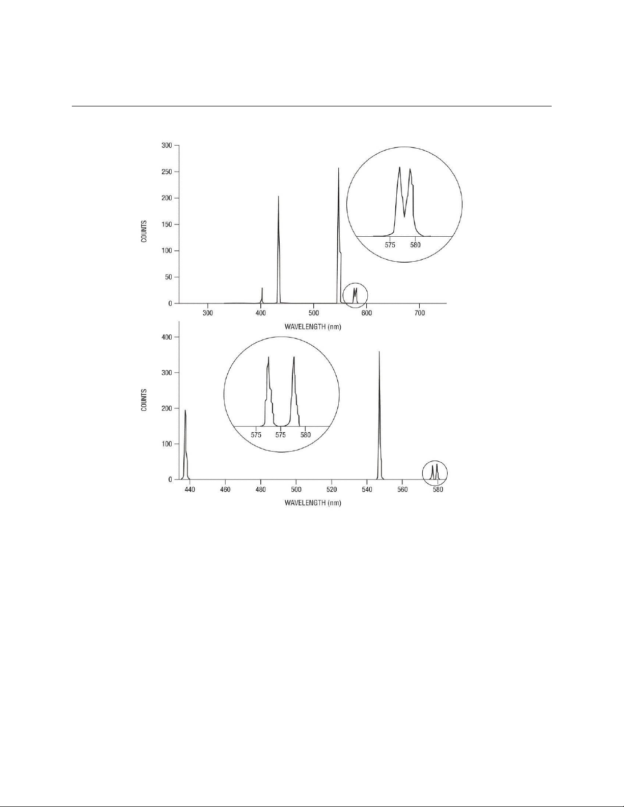
M77781A
MS257™ USB/RS232
MONOCHROMATOR AND SPECTROGRAPH
63
400 l/mm grating
1200 l/mm grating
Note the difference in
wavelength range and
resolution of the 577 and
579 doublet.
A glass filter was used to
block the second order of
UV lines.
Figure 24: Grating
Resolution
When spectrographs are used with diode arrays and CCD detectors, the resolution is often limited by the
pixel width. Nyquist sampling theory leads to calculating the resolution as if an exit slit were equal to two
pixels. Thus the limiting resolution of an MS257 with a diode array and 25 μm wide pixels would be about
0.2 nm.
Page 64

M77781A
MS257™ USB/RS232
MONOCHROMATOR AND SPECTROGRAPH
64
Grating Orders
Gratings have the property of dispersing light into a series of orders (See Figure 25). The zero order is
simply reflected light, and zero order light defines the zero degree grating angle in a monochromator. The
phenomenon of multiple orders can be an advantage since the 2nd order has twice the dispersion of the
first order, and so on. But it also has disadvantages, mainly the lack of efficiency in higher orders. For
example, if light with a wavelength of 600 nm is dispersed by a grating at a diffraction angle of say 15°
then so is a small fraction of light of wavelength 300 nm (the 2nd order), and also 200 nm (the 3rd order).
These different wavelengths will all be focused onto the same location at the exit of the monochromator,
and hence be recorded erroneously as 600 nm light by a detector. Diffraction orders are an overlapping of
orders.
Additionally, there are positive and negative orders. Negative orders have diffraction angles which direct
the light at angles greater than the zero order reflected beam. Positive orders have diffraction angles
which direct the light at angles less than the zero order reflected beam. Most light energy is dispersed into
the first order and in the direction of the blaze.
NOTE: negative orders are defined as orders, which are at angles exceeding that of the zero order.
Positive orders are not shown for clarity in Figure 25.
In order to take truly accurate readings, it is necessary to eliminate multiple orders. This is done by using
order sorting filters. A filter is needed when light is being measured at twice the lowest detectable
wavelength. For example, if silica optics are being used in air, the lowest detectable wavelength is about
180 nm. A 360 nm high pass filter would be required when 360 nm light is being measured. It can be
inconvenient to change filters when long scans are being made unless the monochromator and filter
wheel are under automatic computer control. The MS257 allows one to take long scans and change filters
without interrupting the scan.
Figure 25: Diffraction
Orders
Page 65

M77781A
MS257™ USB/RS232
MONOCHROMATOR AND SPECTROGRAPH
65
Blaze
The blaze wavelength is the wavelength at which the most energy is dispersed. Gratings can be blazed
by making the groove faces at a specific angle to the grating surface. The blaze wavelength is achieved
by cutting a groove with an angle such that the facet normal bisects the angle between the incident and
diffracted rays (see Figure 23). Blaze is important because it allows a grating to be chosen for optimal
efficiency in a given wavelength range. As a general rule, one should select a grating with a blaze
wavelength at the extreme short wavelength end of the region of interest. This is because the majority of
sources and detectors are more efficient at longer wavelengths. The selection of a grating blazed at a
short wavelength compensates for the lack of radiation and detector sensitivity in that wavelength region.
Efficiency
The greatest efficiency one can expect for a grating at the blaze wavelength is about 80%. Thus 80% of
the incoming radiation at that wavelength is diffracted into the 1st order. The rest is lost to the remaining
orders (both positive and negative), absorption and scatter. Light of half the blaze wavelength, which is
diffracted with a low efficiency in the first order, will often have a greater efficiency in the second order
than in the first. For example, a grating with a blaze wavelength at 500 nm has an efficiency of only 10%
for first order 250 nm light. In the second order, the efficiency of the 250 nm light is 30%.
Sinusoidally grooved gratings have very flat efficiency curves across the operating wavelength range,
usually substantially below 50%. Such gratings are regarded as unblazed.
Page 66

M77781A
MS257™ USB/RS232
MONOCHROMATOR AND SPECTROGRAPH
66
Polarization
Figure 26: Polarization and Efficiency
The diffraction efficiency of a grating usually depends on the polarization of the radiation incident I (on the
grating (See Figure 26). This figure shows the effect of polarization on the grating efficiency of a 1200
I/mm diffraction grating.
Ruled Gratings
The grating grooves can be ruled by a mechanical ruling engine, or etched using a holographic process.
Ruled gratings technology lends itself to having a blaze angle formation, to offer the highest efficiency at
the blaze wavelength. They are widely thought to cause a great degree of light scattering, but this is no
longer true. New ruled gratings use interferometrically controlled ruling engines. This produces very
accurate grooves, and very little stray light.
Holographic Gratings
Holographic gratings are created using a interferometric hologram and an etching process. They have the
reputation for being the “best” gratings, but this is not necessarily the case. Sinusoidally grooved gratings
produce very little scattered light but have low flat efficiency curves, a though they are generally quite
broad. The blazed holographic gratings use etching during the interferometric process, or an ion gun to
form a blaze angle in a secondary process. The former does not produce strong blazing. While
holographic gratings produce high efficiencies at the blaze wavelengths, there is also an increase in stray
light due to the formation of microstructure along the edges of the grooves. Oriel Instruments offers both
rules and holographic gratings to provide the best combination of blaze, efficiency and low light scatter for
different wavelength ranges.
Page 67

M77781A
MS257™ USB/RS232
MONOCHROMATOR AND SPECTROGRAPH
67
12 DECLARATION OF CONFORMITY
EC DECLARATION OF CONFORMITY
Manufacturer’s name: Newport Corporation
Manufacturer’s address:
150 Long Beach Boulevard
Stratford, CT 06615 USA
Declares that the product:
Product Name: MS257 USB/RS232
Model Number: 77781, 77782
Type of equipment:
Electrical equipment for measurement, control and laboratory
use in industrial locations
conforms to the following Product Specifications:
Safety: EN
EMC: EN 61326-1:2006 +cor:2008 +cor:2010
61010-1:2010
complies with the following Directives:
2004/108/EC EMC Directive
and accordingly, carries the mark
2006/95/EC Low Voltage Directive
mark affixed: Beaune;
Domenic Assalone
Site Manager, Oriel Products Division Group Director, PPT Instrument and Motion Europe
Bruno Rety Authorized to compile technical
documentation
150 Long Beach Boulevard Micro-Controle Division of Newport Corporation
Stratford, CT 06615 USA Zone Industrielle
45340 Beaune la Rolande, France
01/06/2012
Page 68

M77781A
MS257™ USB/RS232
MONOCHROMATOR AND SPECTROGRAPH
68
13 WARRANTY AND RETURNS
13.1 CONTACTING ORIEL INSTRUMENTS
Oriel Instruments belongs to Newport Corporation's family of brands. Thanks to a steadfast
commitment to quality, innovation, hard work and customer care, Newport is trusted the world over
as the complete source for all photonics and laser technology and equipment.
Founded in 1969, Newport is a pioneering single-source solutions provider of laser and photonics
components to the leaders in scientific research, life and health sciences, photovoltaics,
microelectronics, industrial manufacturing and homeland security markets.
Newport Corporation proudly serves customers across Canada, Europe, Asia and the United
States through 9 international subsidiaries and 24 sales offices worldwide. Every year, the
Newport Resource catalog is hailed as the premier sourcebook for those in need of advanced
technology products and services. It is available by mail request or through Newport's website.
The website is where one will find product updates, interactive demonstrations, specification charts
and more.
To obtain information regarding sales, technical support or factory service, United States and
Canadian customers should contact Oriel Instruments directly.
Oriel Instruments
150 Long Beach Boulevard
Stratford, CT 06615 USA
Telephone: 800-714-5393 (toll-free in United States)
203-377-8282
Fax: 203-378-2457
Sales: oriel.sales@newport.com
Technical assistance: oriel.tech@newport.com
Repair Service: rma.service@newport.com
Customers outside of the United States must contact their regional representative for all sales,
technical support and service inquiries. A list of worldwide representatives can be found on
Oriel's website: http://www.newport.com/oriel.
Page 69

M77781A
MS257™ USB/RS232
MONOCHROMATOR AND SPECTROGRAPH
69
13.2 REQUEST FOR ASSISTANCE / SERVICE
Please have the following information available when requesting assistance or service:
Contact information for the owner of the product.
Instrument model number (located on the product label).
Product serial number and date of manufacture (located on the product label).
Description of the problem.
To help Oriel's Technical Support Representatives diagnose the problem, please note the
following:
Is the system used for manufacturing or research and development?
What was the state of the system right before the problem?
Had this problem occurred before? If so, when and how frequently?
Can the system continue to operate with this problem, or is it non-operational?
Were there any differences in the application or environment before the problem occurred?
13.3 REPAIR SERVICE
This section contains information regarding factory service for this product. The user should not
attempt any maintenance or service of the system beyond the procedures outlined in this manual.
This product contains no user serviceable parts other than what is noted in this manual. Any
problem that cannot be resolved should be referred to Oriel Instruments.
If the instrument needs to be returned for service, a Return Material Authorization (RMA) number
must be obtained prior to shipment to Oriel Instruments. This RMA number must appear on both
the shipping container and the package documents.
Return the product to Oriel Instruments, freight prepaid, clearly marked with the RMA number and
it will either be repaired or replaced it at Oriel's discretion.
Oriel is not responsible for damage occurring in transit. The Owner of the product bears all risk of
loss or damage to the returned Products until delivery at Oriel's facility. Oriel is not responsible for
product damage once it has left the facility after repair or replacement has been completed.
Oriel is not obligated to accept products returned without an RMA number. Any return shipment
received by Oriel without an RMA number may be reshipped by Newport, freight collect, to the
Owner of the product.
Page 70

M77781A
MS257™ USB/RS232
MONOCHROMATOR AND SPECTROGRAPH
70
13.4 NON-WARRANTY REPAIR
For Products returned for repair that are not covered under warranty, Newport's standard repair
charges shall be applicable in addition to all shipping expenses. Unless otherwise stated in
Newport's repair quote, any such out-of-warranty repairs are warranted for ninety (90) days from
date of shipment of the repaired Product.
Oriel will charge an evaluation fee to examine the product and determine the most appropriate
course of action. Payment information must be obtained prior to having an RMA number
assigned. Customers may use a valid credit card, and those who have an existing account with
Newport Corporation may use a purchase order.
When the evaluation had been completed, the owner of the product will be contacted and notified
of the final cost to repair or replace the item. If the decision is made to not proceed with the
repair, only the evaluation fee will be billed. If authorization to perform the repair or provide a
replacement is obtained, the evaluation fee will be applied to the final cost. A revised purchase
order must be submitted for the final cost. If paying by credit card, written authorization must be
provided that will allow the full repair cost to be charged to the card.
13.5 WARRANTY REPAIR
If there are any defects in material or workmanship or a failure to meet specifications, notify Or iel
Instruments promptly, prior to the expiration of the warranty.
Except as otherwise expressly stated in Oriel's quote or in the current operating manual or other
written guarantee for any of the Products, Oriel warrants that, for the period of time set forth below
with respect to each Product or component type (the "Warranty Period"), the Products sold
hereunder will be free from defects in material and workmanship, and will conform to the
applicable specifications, under normal use and service when correctly installed and maintained.
Oriel shall repair or replace, at Oriel's sole option, any defective or nonconforming Product or part
thereof which is returned at Buyer's expense to Oriel facility, provided, that Buyer notifies Oriel in
writing promptly after discovery of the defect or nonconformity and within the Warranty Period.
Products may only be returned by Buyer when acc ompanied by a return material authorization
number ("RMA number") issued by Oriel, with freight prepaid by Buyer. Oriel shall not be
responsible for any damage occurring in transit or obligated to accept Products returned for
warranty repair without an RMA number. Buyer bears all risk of loss or damage to the Products
until delivery at Oriel's facility. Oriel shall pay for shipment back to Buyer for Products repaired
under warranty.
WARRANTY PERIOD
All Products (except consumables such as lamps, filters, etc) described here are warranted for a
period of twelve (12) months from the date of shipment or 3000 hours of operation, whichever
comes first.
Lamps, gratings, optical filters and other consumables / spare parts (whether sold as separate
Products or constituting components of other Products) are warranted for a period of ninety (90)
days from the date of shipment.
Page 71

M77781A
MS257™ USB/RS232
MONOCHROMATOR AND SPECTROGRAPH
71
WARRANTY EXCLUSIONS
The above warranty does not apply to Products which are (a) repaired, modified or altered by any
party other than Oriel; (b) used in conjunction with equipment not provided or authorized by Oriel;
(c) subjected to unusual physical, thermal, or electrical stress, improper installation, misuse,
abuse, acc ident or negligence in use, storage, transportation or handling, alteration, or tampering,
or (d) considered a consumable item or an item requiring repair or replacement due to normal
wear and tear.
DISCLAIMER OF WARRANTIES; EXCLUSIVE REMEDY
THE FOREGOING WARRANTY IS EXCLUSIVE AND IN LIEU OF ALL OTHER WARRANTIES.
EXCEPT AS EXPRESSLY PROVIDED HEREIN, ORIEL MAKES NO WARRANTIES, EITHER
EXPRESS OR IMPLIED, EITHER IN FACT OR BY OPERATION OF LAW, STATUTORY OR
OTHERWISE, REGARDING THE PRODUCTS, SOFTWARE OR SERVICES. NEWPORT
EXPRESSLY DISCLAIMS ANY IMPLIED WARRANTIES OF MERCHANTABILITY OR FITNESS
FOR A PARTICULAR PURPOSE FOR THE PRODUCTS, SOFTWARE OR SERVICES. THE
OBLIGATIONS OF ORIEL SET FORTH IN THIS SECTION SHALL BE ORIEL'S SOLE LIABILITY,
AND BUYER'S SOLE REMEDY, FOR BREACH OF THE FOREGOING
WARRANTY. Representations and warranties made by any person including distributors, dealers
and representatives of Oriel / Newport Corporation which are inconsistent or in conflict with the
terms of this warranty shall not be binding on Oriel unless reduced to writing and approved by an
expressly an authorized officer of Newport.
13.6 LOANER / DEMO MATERIAL
Persons receiving goods for demonstrations or temporary use or in any manner in which title is not
transferred from Newport shall assume full responsibility for any and all damage while in their care,
custody and control. If damage occurs, unrelated to the proper and warranted use and
performance of the goods, recipient of the goods accepts full responsibility for restoring the goods
First printing 2012
© 2012 by Newport Corporation, Irvine, CA. All rights reserved.
No part of this manual may be reproduced or copied without the prior written approval of Newport Corporation.
This manual has been provided for information only and product specifications are subject to change without notice.
Any change will be reflected in future printings.
Newport Corporation 1791 Deere Avenue Irvine, CA, 92606 USA
to their original condition upon delivery, and for assuming all costs and charges.
 Loading...