

Page 1
s
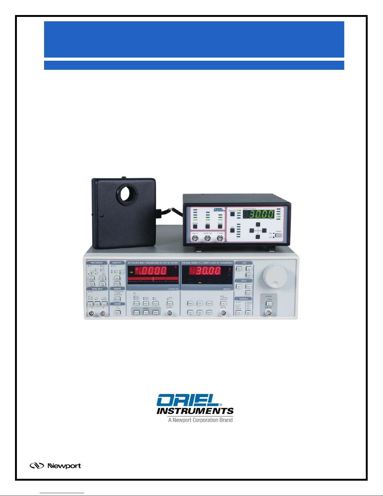
LIDA-SRS-KIT
Lock-In Digital Amplifier
Radiometry System
Family of Brands – ILX Lightwave® • New Focus™ • Ophir® • Corion • Richardson Gratings™ • Spectra-Physics
User's Manual
®
MLIDA, Rev A
Page 2

TABLE OF CONTENTS
1 GENERAL INFORM ATION .................................................................................................................. 4
1.1 SYMBOLS AND DEFINITIONS ............................................................................................. 4
1.2 GENERAL WARNINGS ......................................................................................................... 6
1.3 ELECTRICAL HAZARDS ....................................................................................................... 6
1.4 FIRE HAZARDS ..................................................................................................................... 6
2 INTRODUCTION .................................................................................................................................. 7
3 FEATURES .......................................................................................................................................... 8
3.1 SR810 LOCK-IN DIGITAL AMPLIFIER (LIDA) ...................................................................... 8
3.1.1 Input Channel ............................................................................................ 9
3.1.2 Extended Dynamic Reserve ...................................................................... 9
3.1.3 Digital Filtering ........................................................................................... 9
3.1.4 Digital Phase Shifting ................................................................................. 9
3.1.5 Frequency Synthesizer .............................................................................. 9
3.1.6 Auto Functions ......................................................................................... 10
3.1.7 Analog Inputs and Outputs ...................................................................... 10
3.1.8 Internal Memory ....................................................................................... 10
3.1.9 Easy Operation ........................................................................................ 10
4 BASIC SYSTEM SET UP .................................................................................................................... 11
4.1 WHAT’S INCLUDED ............................................................................................................ 11
4.2 REQUIRED ITEMS .............................................................................................................. 11
4.3 UNPACKING ........................................................................................................................ 11
4.4 CHOOSING A LOCATION ................................................................................................... 12
4.5 CHOPPER CONTROLLER CONNECTIONS ...................................................................... 12
4.6 COMPUTER CONNECTIONS ............................................................................................. 13
4.7 DETECTOR CONNECTIONS .............................................................................................. 14
4.8 ELECTRICAL CONNECTIONS ........................................................................................... 16
5 SOFTWARE CONFIGURATION ........................................................................................................ 17
5.1 ESTABLISHING COMMUNICATION ................................................................................... 17
5.2 SETTING OPERATING PARAMETERS .............................................................................. 19
6 BASIC OPERATION........................................................................................................................... 20
6.1 SET INTERNAL FREQUENCY GENERATOR .................................................................... 20
6.2 SET SIGNAL INPUT MODE ................................................................................................ 20
6.3 SET AUTO GAIN AND AUTO PHASE ................................................................................. 21
7 ADVANCED CONFIGURATIONS AND APPLICATIONS .................................................................. 22
7.1 RATIO MODE SETUP .......................................................................................................... 22
7.2 CALIBRATION ..................................................................................................................... 24
7.3 QUANTUM EFFICIENCY MEASUREMENTS ..................................................................... 26
8 DETECTORS ..................................................................................................................................... 28
8.1 ORIEL LIDA-COMPATIBLE DETECTORS .......................................................................... 28
8.2 OTHER DETECTORS .......................................................................................................... 29
9 SPECIFICATIONS.............................................................................................................................. 30
10 WARRANTY AND SERVICE ............................................................................................................. 32
10.1 CONTACTING NEWPORT CORPORATION ...................................................................... 32
10.2 REQUEST FOR ASSISTANCE / SERVICE ......................................................................... 33
10.3 REPAIR SERVICE ............................................................................................................... 33
10.4 NON-WARRANTY REPAIR ................................................................................................. 33
10.5 WARRANTY REPAIR .......................................................................................................... 34
10.6 LOANER / DEMO MATERIAL .............................................................................................. 35
Family of Brands – ILX Lightwave® • New Focus™ • Ophir® • Corion • Richardson Gratings™ • Spectra-Physics
MLIDA, Rev A
®
Page 3

LIST OF FIGURES
Figure 1: Typical experimental setup ........................................................................................................... 7
Figure 2: The LIDA-SRS-KIT ....................................................................................................................... 7
Figure 3: Chopper Synchronization Connections ...................................................................................... 12
Figure 4: GPIB/USB Cable Connection ..................................................................................................... 13
Figure 5: Detector Signal Output Connecti on ............................................................................................ 14
Figure 6: Detector Amplifier Cable Model CBL-70054-LIDA ..................................................................... 15
Figure 7: Amplifier Power Connectio n on SR810 with LIDA -Compatible Oriel Detector ........................... 15
Figure 8: Stand-Alone Preamplifier 70710 (left) with PMT Housing 70693 ............................................... 15
Figure 9: Main Power Connector and On/Off Switch L ocatio ns ................................................................ 16
Figure 10: SR810 GPIB Address Selection ............................................................................................... 17
Figure 11: View GPIB Address on SR810 ................................................................................................. 18
Figure 12: LIDA Communication Established ............................................................................................ 18
Figure 13: Setting Operating Parameters in TracQ Basic .......................................................................... 19
Figure 14: Source Button, SINE out and Frequency Selector Knob ........................................................... 20
Figure 15: Signal Input Connections ........................................................................................................... 20
Figure 16: Auto Gain and Phase Buttons ................................................................................................... 21
Figure 17: Reference Connections ............................................................................................................ 22
Figure 18: Reference Display..................................................................................................................... 23
Figure 19: Ratio Measurement Configur ati on ............................................................................................ 23
Figure 20: Oriel Monochromator Integration with TracQ Basic .................................................................. 24
Figure 21: Calibrated Detector File ............................................................................................................ 25
Figure 22: Setting Detector Gain Value ..................................................................................................... 25
Figure 23: QE Measurement Configurat ion ............................................................................................... 26
Figure 24: Reference Spectra Measurement Using TracQ Basic .............................................................. 27
Figure 25: QE Measurements of Samples ................................................................................................. 27
Figure 26: Oriel HgCdZnTe Detector ......................................................................................................... 29
Family of Brands – ILX Lightwave® • New Focus™ • Ophir® • Corion • Richardson Gratings™ • Spectra-Physics
®
MLIDA, Rev A
Page 4
1 GENERAL INFORMATION
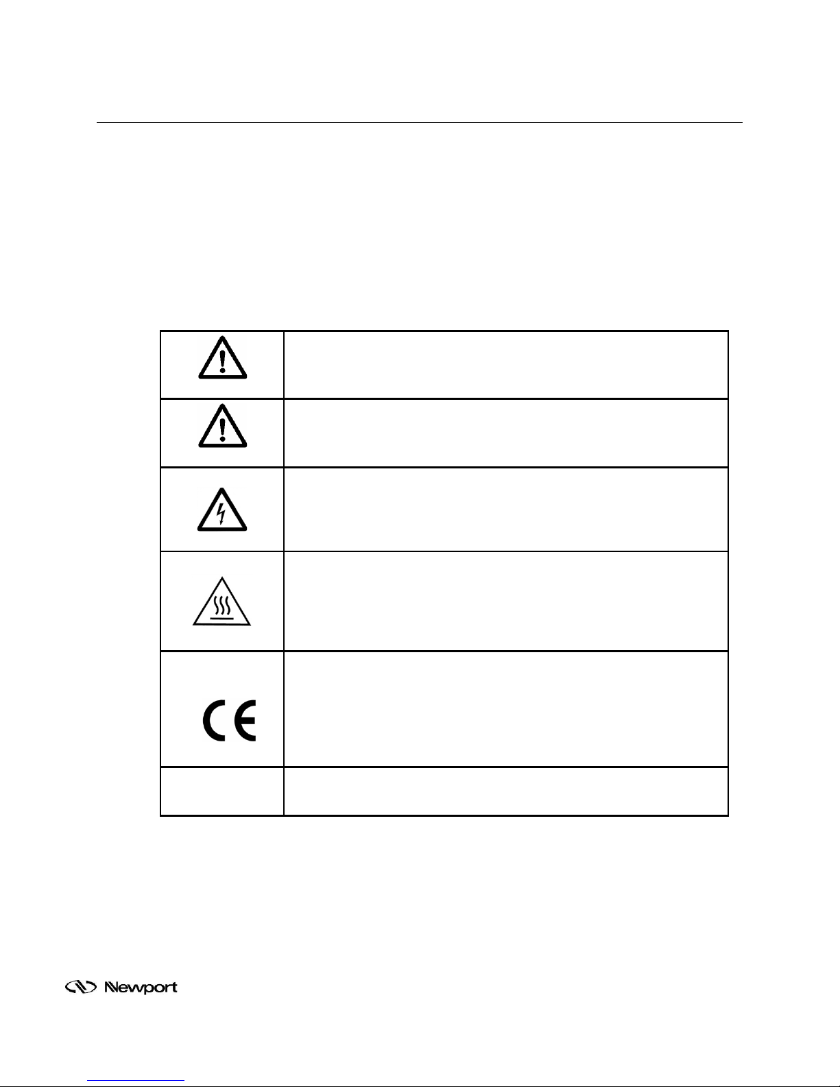
with all applicable European Union (CE) regulations and
Thank you for your purchase of this Lock-In Digital Amplif ier System from Oriel Instruments.
Please carefully read the following important safety precautions prior to unpacking and operating this
equipment. In additio n, pleas e ref er to the com plete U ser ’s Manual and all oth er doc um entation pro vided
for additional important notes and cautionary statements regarding the use and operation of the system.
Do not attempt to operate the system without reading all the information provided with each of the
components.
1.1 SYMBOLS AND DEFINITIONS
WARNING
Situation has the potential to cause bodily harm or death.
CAUTION
Situation has the potential to cause damage to property or equipment.
ELECTRICAL SHOCK
Hazard arising from dangerous voltage. Any mishandling cou ld result
in irreparable damage to the equipment, and personal injury or death.
HOT SURFACE
Hazard arising from hot surf aces. Objects or per sons mak ing contact
with a hot surface c ould r es ult in p ers ona l inj ury or damage to property
or equipment.
Note:
EUROPEAN UNION CE MARK
The presence of the CE Mark on Newport Corporation equipment
means that it has been designed, tested and certified as complying
recommendations.
Additional important information the user or operator should consider.
Family of Brands – ILX Lightwave® • New Focus™ • Ophir® • Corion • Richardson Gratings™ • Spectra-Physics
MLIDA, Rev A
®
Page 5
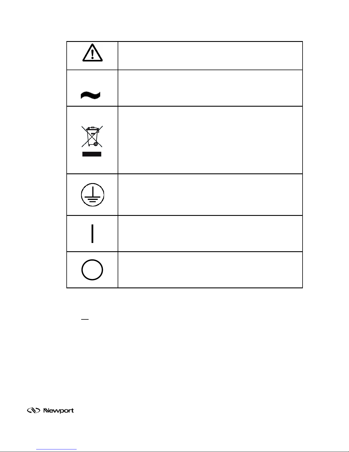
WARNING
equipment at the time of disposal will help to conserve natural
Situation has the potential to cause bodily harm or death.
ALTERNATING (AC) VOLTAGE
This international symbol designates an alternating voltage.
WEEE
This symbol on the product or on its packaging indicates that this
product must not be dis posed of with regular waste. Instead, it is the
user’s responsibility to dispose of waste equipment according to the
local laws. The separate collection and recycling of the waste
resources and ensure that the materials are r ecycled in a m anner that
protects human health and the environment.
PROTECTIVE CONDUCTOR TERMINAL
The protective conduct or term inal symbol in th e above figure ident ifies
the location of the b onding term inal inside the unit, whic h is bonded to
conductive accessible parts of the enclosure for safety purposes.
ON
The ON symbol in the above figure indicates the ON position of the
power switch.
OFF
The OFF symbol in the above figure indicates the OFF position of the
power switch.
Please read all instructions that were provided prior to operation of the system. If
there are any questions, please contact Oriel Instruments or the representative
through whom the system was purchased.
Family of Brands – ILX Lightwave® • New Focus™ • Ophir® • Corion • Richardson Gratings™ • Spectra-Physics
MLIDA, Rev A
®
Page 6

1.2 GENERAL WARNINGS
• Read all warnings and operating instructions for this system prior to setup and use.
• Do not use this equipment in or near water.
• To prevent damage to the equipment, read the instructions in the equi pment manual for proper
input voltage.
• This equipment is grounded through the grounding conductor of the power cords.
• Route power cords and other cables so they are not likely to be damaged.
• Disconnect power before cleaning the equ ipment
• Do not use liquid or aerosol cleaners; use only a damp lint-free cloth.
• Lock out all electrical power sources before servicing the equipment.
• To avoid explosion, do not operate this equipment in an explosive atmosphere.
• Qualified service personnel should perform safety checks after any service.
• If this equipment is us ed in a m anner not s pecified i n this m anual, the protection provide d by this
equipment may be impaired.
• To prevent damage to equipment when replacing fuses, locate and correct the problem that
caused the fuse to blow before re-applying power.
• Do not block ventilation openings.
• Do not position this produc t in such a m anner that would m ake it diffic ult to discon nect the po wer
cords.
• Use only the specified replacement parts.
• Follow precautions for static sensitive devices when handling this equipment.
• This product should only be powered as described in the manual.
• Do not remove the cover for normal usage
1.3 ELECTRICAL HAZARDS
Make all connections to or from the power supply with the power off.
Do not use the lock-in digital amplifier without its cover in place. Lethal voltages are present inside.
1.4 FIRE HAZARDS
To avoid fire hazard, use only the specified fuses with the correct type number, voltage and
current ratings as referenced in the appropriate locations in the service instructions or on the
equipment. Only qualified service personnel should replace fuses.
Family of Brands – ILX Lightwave® • New Focus™ • Ophir® • Corion • Richardson Gratings™ • Spectra-Physics
®
MLIDA, Rev A
Page 7
2 INTRODUCTION
The LIDA-SRS-KIT is an easily integrated kit, which provides a powerful measurement metrology for
experiments by removing bac kground signals throug h phase sensitive d etection. This tec hnique is often
used to extract very small signals obscured by noise sources many times larger by locking into the
specific modulation frequency of your desired signal.
Oriel created an application kit (LIDA-SRS-KIT) using the Stanford Research Systems (SRS) Lock In
Digital Amplifier (LIDA) model SR810. The LIDA-SRS-KIT includes the ch opper, chopper control, and
lock-in amplif ier and readout (gauge or softwar e) used in a typical experim ental set-up and connects to
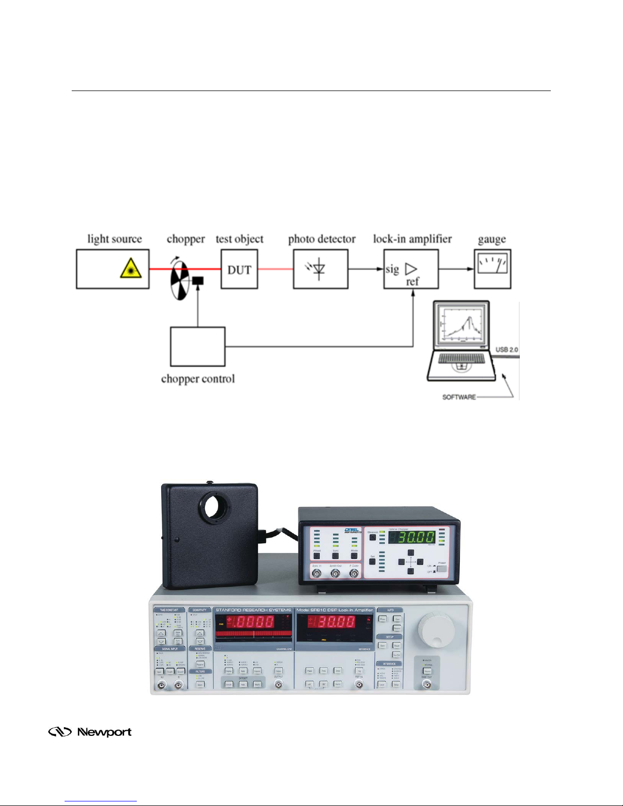
any BN C-ended detector. A typical setup is shown in Figure 1.
Figure 1: Typical experimental setup
In Figure 2, the Oriel model 75160NF chopper controller sits on top of a Stanford Research Systems
(SRS) model SR810 Lock -In Digital Amplifier (LIDA) instrum ent. The chopper is being driven at 30Hz
through the internal frequency generator of the SR810.
Family of Brands – ILX Lightwave® • New Focus™ • Ophir® • Corion • Richardson Gratings™ • Spectra-Physics
Figure 2: The LIDA-SRS-KIT
®
MLIDA, Rev A
Page 8

3 FEATURES
The LIDA-SRS-KIT includes the chopper, chopper control, lock-in amplifier, and readout (gauge or
software) used in a typical experimental set-up and connects to any BNC-ended detector.
The Stanford Research Systems (SRS) SR810 Lock-In-Digital-Amplifier (LIDA) provides high
performance at a reasonable cost and integrates into Oriel’s product line.
• Single Channel
• Higher resolution frequency control
• Voltage or current input
• Wider range of time constant
• Internal or external reference frequency source
• Auto-gain, -phase, -reserve, and –offset
• Standard RS-232 and GPIB (IEEE488.2) interfaces
• “AUX IN” provides inputs for reference channels
• Reference input corrects your measurement channel to compensate for source drift
• “TTL OUT” controls the external chopper
• “PREAMP” connection may be used to power up detector pre-amplifiers
3.1 SR810 LOCK-IN DIGIT AL AMPLIFIER (LIDA)
The SR810 Lock-in Digital Amplifier (LIDA) provides high performance at a reasonable cost.
Simultaneously displays the magnitude and uses digital signal processing (DSP) to replace the
demodulators, output f ilters, and amplifiers found in conventional lock-ins. The SR8 10 provides
uncompromised perf ormance with an operating range of 1 MHz to 102 kHz and 100 dB of drift -free
dynamic reserve.
Lock-In Digital Amplifier model SR810
Oriel model 75160NF Optical Chopper System
Cable, BNC male to male (2 meters long)
Oriel TracQ Basic software
Cable, BNC male to male (2 meters long)
Cable, GPIB to USB
U.S. and European power cords
An electronic copy of this user’s manual on a thumb drive
Family of Brands – ILX Lightwave® • New Focus™ • Ophir® • Corion • Richardson Gratings™ • Spectra-Physics
MLIDA, Rev A
®
Page 9

3.1.1 Input Channel
The SR810 Lock-In Amplifiers have differential inputs with 6 nV/√Hz input noise. The input
impedance is 10 MΩ, and minimum full-sc ale input v oltag e sensit ivit y is 2 nV . The in put can also
be configured for cur rent meas urem ents wit h selec tabl e current ga ins of 106 and 108 V/A. A line
filter (50 Hz or 60 Hz) and a 2× line f ilter (100 H z or 120 H z) are provi ded to el iminate li ne relate d
interference. However, unlike conventional lock-in amplifiers, no tracking band-pass filter is
needed at the input. This filter is used by conventional lock-ins to increase dynamic reserve.
Unfortunately, band pas s filters also intr oduce noise, am plitude and phase err or, as well as dr ift.
The DSP based design of these lock-ins has such inherently large dynamic reserve that no
tracking band-pass filter is necessary.
3.1.2 Extended Dynamic Reserve
The dynamic res erve of a l ock-in am plif ier at a given f ull-scale input voltage is the ratio (in dB) of
the largest interfering signal to the full-scale input voltage. The largest interfering signal is
defined as the amplitude of the largest signal at an y frequency that can be appl ied to the input
before the lock-in cannot measure a signal with its specified accuracy.
Conventional lock-in amplifie rs use an analog d emodulator to mix an inp ut si gna l with a r ef er ence
signal. Dynamic reserve is limited to about 60 dB and these instruments suffer from poor
stability, output drif t, and excessive gain and phase error. Demodul ation in the SR810 Lock-In
Amplifier is accom plished by sampling the i nput signal with a high-precision A/D converter, and
multiplying the digitized input by a synthesized reference signal. This digital demodulation
technique results in m ore than 100 dB of true dynamic r eserve (no prefiltering). It is f ree of the
errors associated with analog instruments.
3.1.3 Digital Filtering
The digital signal proc essor also handles the tas k of output filtering, allowing t ime cons tants from
10 µsec to 30,000 s, with a choice of 6, 12, 18 and 24 dB/oct roll-off. For low frequency
measurements (below 200 H z), synchronous filters c an be engaged to notch out m ultiples of the
reference f requency. Since the harmonics of the referenc e have been eliminated, (notabl y 2F),
effective output filtering can be achieved with much shorter time constants.
3.1.4 Digital Phase Shifting
Analog phase shifting circuits have also been replaced with a DSP calculation. Phase is
measured with 0.01° resolution, and the X and Y outputs are orthogonal to 0.001°.
3.1.5 Frequency Synthesizer
The built-in direct digital synthesis (DDS) source generates a very low distortion (-80 dBc)
reference signal . Single f requenc y si ne waves can be generated f rom 1 MHz to 1 02 k Hz with 4½
digits of resolution. Both frequency and amplitude can be set from the front panel or from a
computer. When using an external reference, the synthesized source is phase locked to the
reference signal.
Family of Brands – ILX Lightwave® • New Focus™ • Ophir® • Corion • Richardson Gratings™ • Spectra-Physics
®
MLIDA, Rev A
Page 10

3.1.6 Auto Functions
Auto-functions allow parameters that are frequently adjusted allowing automatic setting by the
instrument. Gain, phase, off s et and d ynam ic r eser ve are eac h quickly optimized with a single key
press. The offset and expand features are useful when examining small fluctuations in a
measurement. T he input signal is quickl y nulled with the auto-offs et function, and resolution is
increased by expandin g ar ound t he r e lat ive v al ue by up to 100×. Harmonic detection is no longer
limited to only the 2F component. Any harmonic (2F, 3F, ... nF) up to 102 kHz can now be
measured without changing the reference frequency.
3.1.7 Analog Inputs and Outputs
The SR810 has user-def ined output for m easuring X, R, X-noise, Aux1, Aux 2, or the ratio of the
input signal to an external voltag e. The SR810 has X and Y analog outp uts (rear panel) that are
updated at 256 kHz. Four auxiliary inputs (16-bit ADCs) are pr ovided for general purpose use,
such as normalizing the input to s ource intens it y fluctuatio ns. Four progr amm abl e outputs (16-bit
DACs) provide voltages fr om -10.5 V to +10.5 V and can be set via the front panel or com puter
interfaces.
3.1.8 Internal Memory
The SR810 Lock-In has an 8,000 point memory buffer for recording the time history of a
measurement at rates up to 512 samples/ s. Data transfers from the buffers using the com puter
interfaces. A trigger input provides externally synchronized data recording.
3.1.9 Easy Operation
The SR810 Lock-In Amplifier is simple to use. All instrument functions are set from the frontpanel keypad, and a spin knob is provided to quickly adjust parameters. Up to nine different
instrument configurat ions can be stored in non-volati le RAM for fas t and easy instrum ent set-up.
Standard RS-232 and GPIB (IEEE-488.2) interfaces allow communication with computers. All
functions can be controlled and read through these interfaces.
Family of Brands – ILX Lightwave® • New Focus™ • Ophir® • Corion • Richardson Gratings™ • Spectra-Physics
®
MLIDA, Rev A
Page 11
4 BASIC SYSTEM SETUP
WARNING
to operate this equipment if there is evidence of
4.1 WHAT’S INCLUDED
The LIDA-SRS-KIT includes the following items:
Lock-In Digital Amplifier model SR810
Oriel model 75160NF Optical Chopper System
Cable, BNC male to male (2 meters long)
Oriel TracQ Basic software
Cable, BNC male to male (2 meters long)
Cable, GPIB to USB
U.S. and European power cords
An electronic copy of this user’s manual on a thumb drive
Please refer to the Optical Chopper System user’s manual for the items provided with the 75160NF.
4.2 REQUIRED ITEMS
The following items are required to be provided by the user for setting up the LIDA:
Computer for TracQ Basic software installation
Optical detector
Detector signal cable with BNC male connector
Refer to the TracQ Basic user’s manual for minimum system requirements for the computer. If an Oriel
LIDA-compatible detector is utilized, it includes a signal cable and amplifier power cable.
4.3 UNPACKING
Remove all items from the shipp ing containers and verif y each item is ac counted for. T he system
is carefully packaged to m inimize the possibi lity of damage during shipm ent. Inspect the ship ping
boxes for external signs of damage or mishandling. Inspect the contents for damage.
If any item is missing or damaged, immediately contact Oriel Instruments or the Newport
representative from whom the system was purchased.
Do not attempt
shipping damage or there is suspicion that the equipment will not
operate correctly. Damaged equipment may present hazards.
Family of Brands – ILX Lightwave® • New Focus™ • Ophir® • Corion • Richardson Gratings™ • Spectra-Physics
®
MLIDA, Rev A
Page 12
4.4 CHOOSING A LOCATION
Choose an installat io n l ocation where the po wer requirements can be met for the s ystem . Be s ure
power is not applied to the system until the setup has been completed.
The environment should be that of a typical laboratory atmosphere, without excessive humidity
and contaminants in th e air. Do not allo w the ventila tion holes on th e system’s components or its
computer to be blocked. Air should be able to circulate freely around the system.
4.5 CHOPPER CONTROLLER CONNECTIONS
A lock-in digital am plifier is c apable of readi ng read choppe d light signa ls from an optical detector .
Therefore, it is required to ins tall the 75160NF Optical Chopper S ystem. Install a wheel into the
chopper head based on th e des ire d c ho pp ing f r equency and beam si ze. When using a wheel wit h
more than two apertures, install the appropriate aperture disk supplied with the chopper head.
Use the cable supplied with the 75160NF to connect the chopper controller to the enclosed
chopper head. Refer to its user’s manual for more details.
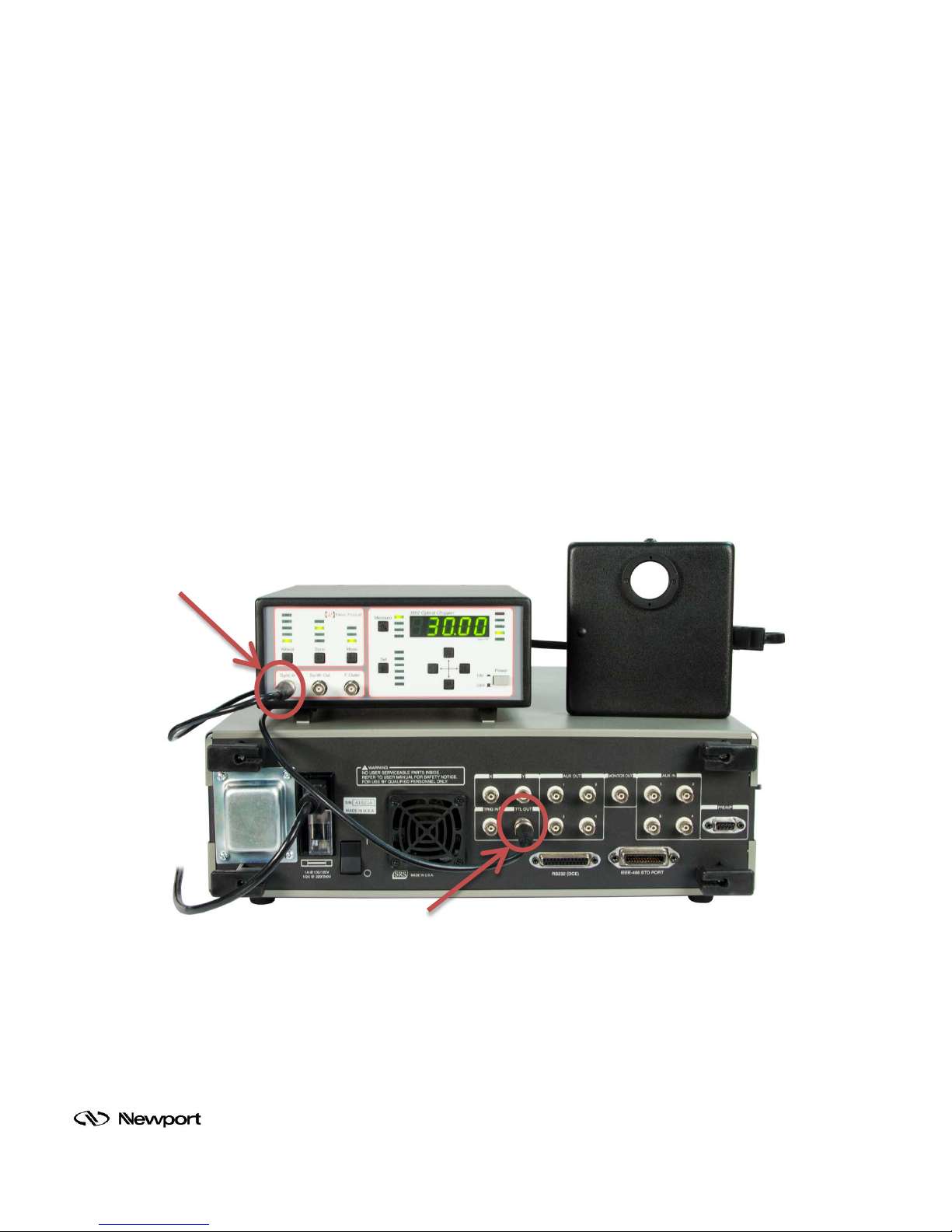
Connect one end of the BNC cable supplied with the LIDA to “TTL OUT” on the back of the
SR810. Connect the other end to “REF” on t he front of the chopper contr oller. T his allows T racQ
Basic software to contr ol the choppin g frequency thro ugh the LIDA. For s ignal reading ac curacy,
the frequency must be synchronized between the LIDA and the chopper.
Figure 3: Chopper Synchronization Conne ctions
Family of Brands – ILX Lightwave® • New Focus™ • Ophir® • Corion • Richardson Gratings™ • Spectra-Physics
®
MLIDA, Rev A
Page 13
4.6 COMPUTER CONNECTIONS
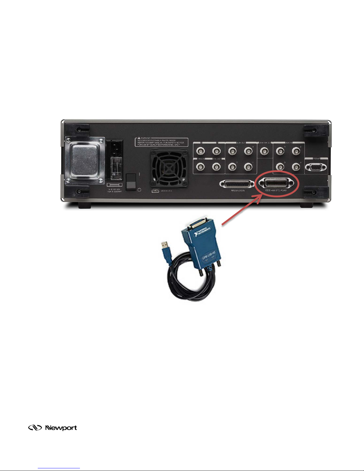
Install the driver provi ded with the G PIB/US B cable from National Instr uments . Connect the cab le
to the GPIB connector on the back of the LIDA and tighten the connections. Plug the USB
connector into the com puter. If suc cessf ully installed, the com puter’s Device Manager will disp lay
“GPIB USB HS”.
For computers which have a GPIB card, a standard GPIB cable may be used. This cable is
available from Newport as model 70038, and is ordered separately.
Family of Brands – ILX Lightwave® • New Focus™ • Ophir® • Corion • Richardson Gratings™ • Spectra-Physics
Figure 4: GPIB/USB Cable Connection
®
MLIDA, Rev A
Page 14
4.7 DETECTOR CONNECTIONS
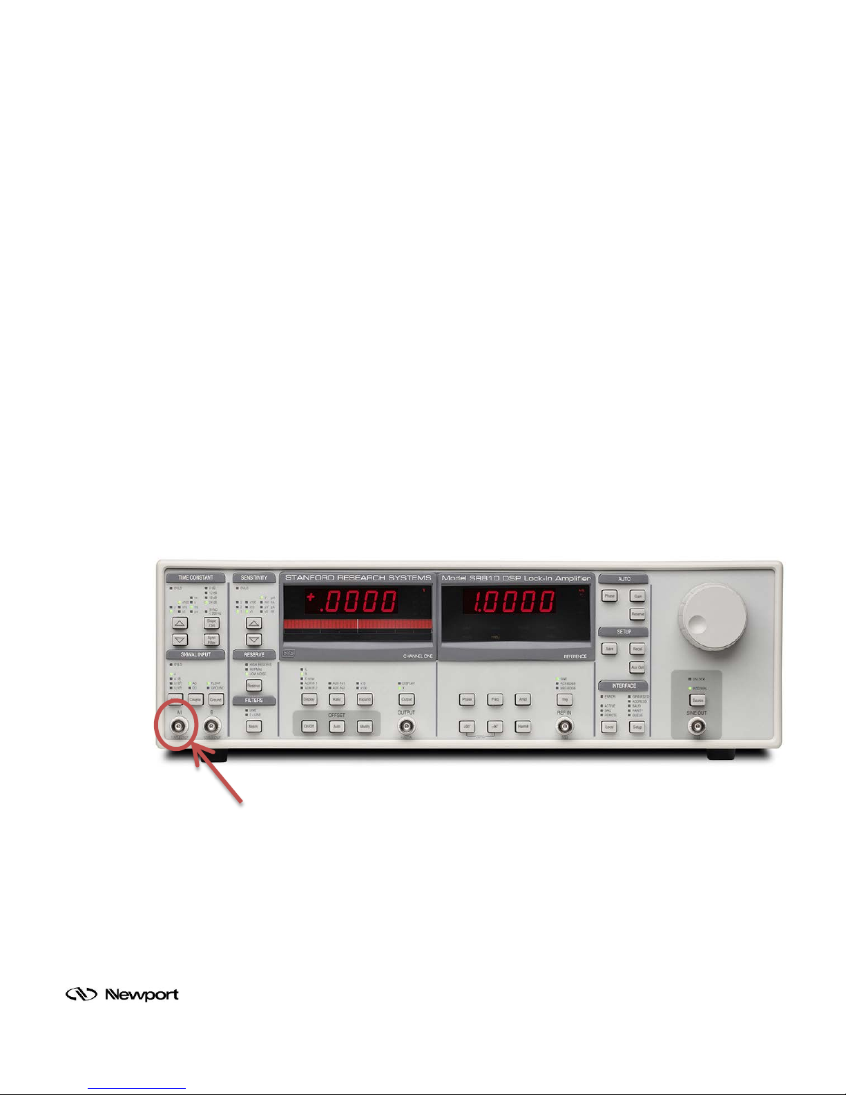
The output signal from the detector is typically connected to the Channel “A” signal input BNC
connector on the front of the SR810. T his connector m ay accept either current or voltage si gnals.
The B output from the pr ea mp (preamp ground) m a y be connect ed to t he B in put of the SR 8 10. I n
this case, use A-B as the input configuration. Be sure to twist the A and B cables to avoid
differential noise pickup between the cables.
Unamplified detector s provide a curr ent signal, while amplified detec tors provide a voltage signal.
If the signal exceeds the maximum which can be read by the SR810, the “OVLD” indicator
illuminates. The SR810 h as greater d ynamic reserve when reading voltage signals, s o the LIDAcompatible detectors of fered by Oriel are a ll amplifie d models . Additionall y, Oriel off ers the 70310
stand-alone current preamplifier to use with unamplified detectors or photomultiplier tubes.
Oriel’s amplified detect ors and s tand-alone current pream plif ier requir e a power sourc e to operate.
The “PREAMP” c onnection on the back of the SR810 is able to provide the power required. It
must be utilized wit h Oriel cable m odel CBL-70054-LI DA only. The user of any other Oriel c able
will damage the amplifier circuit and void the warranty on the detector or stand-alone preamplifier.
This power cable, as well as a BNC signa l cable, are included with all LIDA-compatible detectors
offered by Oriel. For other setups, the CBL-70054-LIDA m ay be purchased separately. To use
this power cable with th e mode l 70310 cur rent pream plifier, th e cab le’s m ini-DIN connec tor can be
cut off and the stripped wire ends may be installed into the preamplifier’s terminal block.
Note: the SR810 does NOT compensate for the gain of the preamp. The SR810 sets both
preamps to their max imum gains. Measurements m ade by the SR810 with a preamp s hould be
divided by the gain of the preamp.
Figure 5: Detector Signal Output Connection
Family of Brands – ILX Lightwave® • New Focus™ • Ophir® • Corion • Richardson Gratings™ • Spectra-Physics
®
MLIDA, Rev A
Page 15
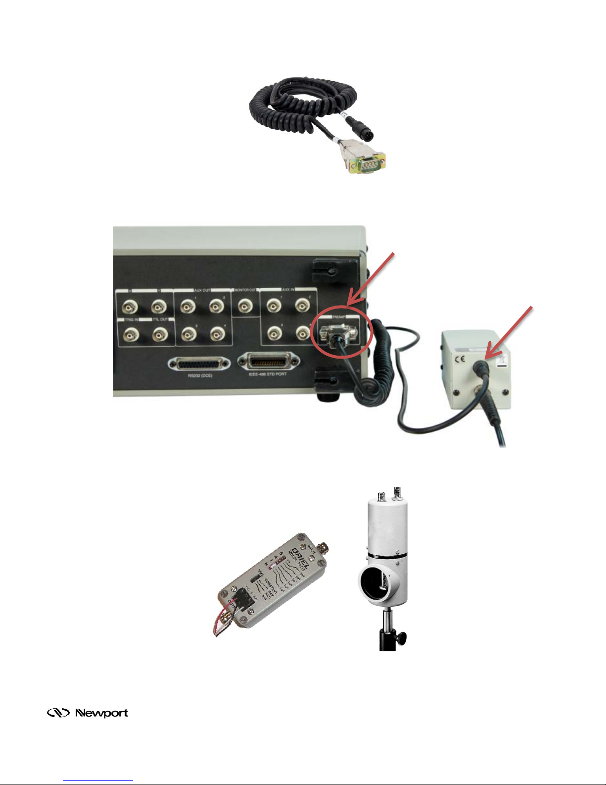
Figure 6: Detector Amplifier Cable Model CBL-70054-LIDA
Figure 7: Amplifier Power Connection on SR810 with LIDA-Compatible Oriel Detector
Figure 8: Stand-Alone Preamplifier 70710 (left) with PMT Housing 70693
Family of Brands – ILX Lightwave® • New Focus™ • Ophir® • Corion • Richardson Gratings™ • Spectra-Physics
MLIDA, Rev A
®
Page 16
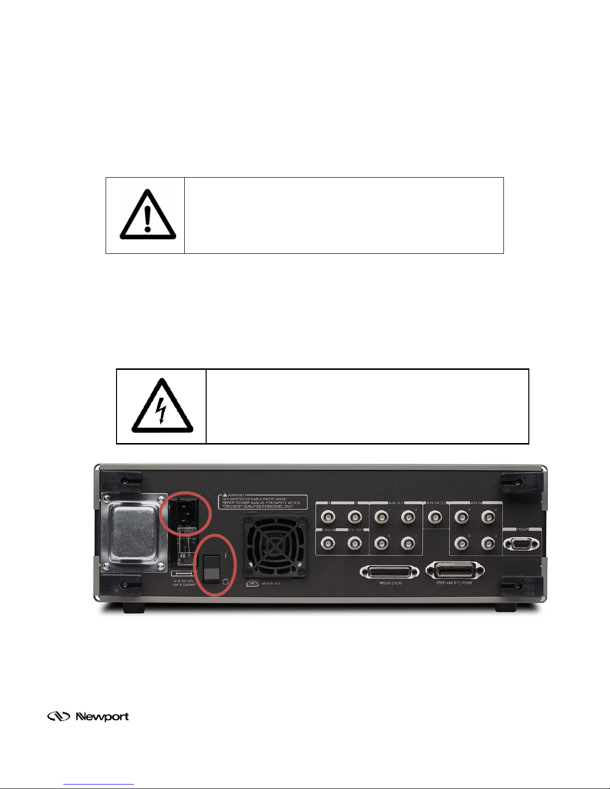
4.8 ELECTRICAL CONNECTIONS
WARNING
prong receptacles only. Failure to observe this
ELECTRICAL SHOCK
Before powering up the system for the first time, it is suggested to have a qualified electrician
verify the wall socket to be used with the LIDA-SRS-KIT meets the requirements for operation as
noted.
Before making an y electrical connections, verify the power s witches are in the off position for the
lock-in digital amplifier and chopper controller.
Refer to the specif ications sec tion of this users ’ manual for the power req uirements f or the lock -in
digital amplifier. Refer to the specifications section of the 75160NF user’s manual for the power
requirements for the chopper controller.
The LIDA-SRS-KIT conforms to CE s tandards for bot h safety and EMC. During norm al use, this
equipment will not p ose any electric al hazards to t he user. Read all warnings before installin g or
operating this system. If there are any questions or concerns, contact Oriel Instruments or the
regional sales representative for Newport.
To avoid electric shock, connect the instrument to properly earthgrounded, 3precaution can result in severe injury or death.
Never attempt to ope n the lock-in digital am plif ier. This items does not
contain any user serv iceable parts. Fa ilure to follow this warning can
result in severe injury or death.
Figure 9: Main Power Connector and On/Off Switch Loc ations
Family of Brands – ILX Lightwave® • New Focus™ • Ophir® • Corion • Richardson Gratings™ • Spectra-Physics
®
MLIDA, Rev A
Page 17
5 SOFTWARE CONFIGURATION
Follow the instructions provided with T r acQ Basic to install the software onto a com puter . The s of tware is
used to control the LIDA settings. After the setup is complet e, TracQ Basic allows the us er to select the
desired chopping frequency and operating parameters for the SR810.
The software is als o able to control various Oriel m onochromators. Please refer to the user’s manual
included with the software for a list of compatible instruments.
5.1 ESTABLISHING COMMUNICATION
The SR810 mus t be connected to th e computer with the GPIB/USB cable and p owered on before
opening the software application. When starting the TracQ Basic software for the first time,
prompts guide th e user to select the det ection instrum ent and monochromator for the system. If
no monochromator instrum ent is to be used, c lick Can cel. Otherwise, s elect th e ins trum ent based
on the instructions provided with the software.
To select the LIDA, navigate to the following folder:
C:\Program Files\Newport – Oriel Instruments\TracQ Basic.
Highlight the folder named “SR810”, then click Select Folder.
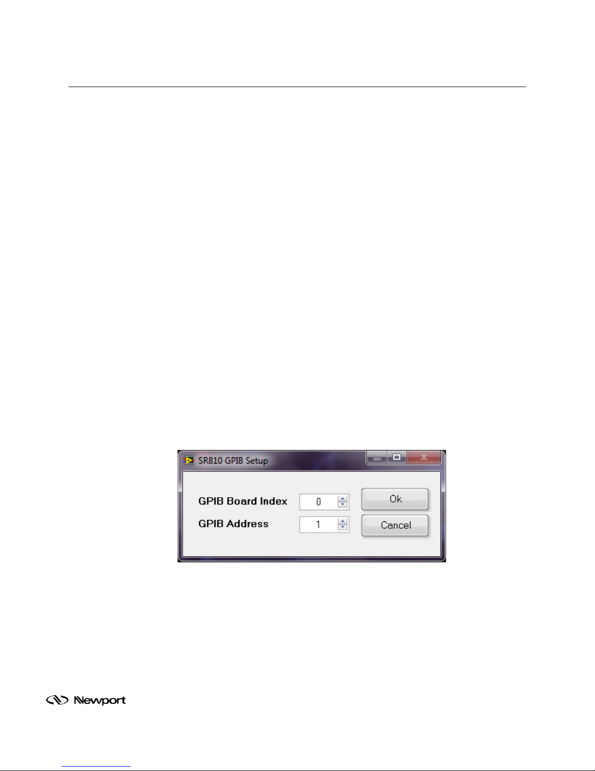
Verify that the indicator o n t he f r ont pane l of the s of twar e is gr een f or t he Detec t io n Inst rument and
monochromator, if utilized. If the SR810 communication cannot be established, go to Detector
Instr. Setup Communication and verify the appropriate GPIB address is selected.
The GPIB address should match the setting on th e SR810. To view the GPIB address on the
SR810, press the Set up button under INTERFACE on the front panel of the inst rument until the
Address LED is illuminated. The right side reference display will show the GPIB address. To
change the address, rotate the SR810 front panel knob.
Figure 10: SR810 GPIB Address Selection
Family of Brands – ILX Lightwave® • New Focus™ • Ophir® • Corion • Richardson Gratings™ • Spectra-Physics
®
MLIDA, Rev A
Page 18
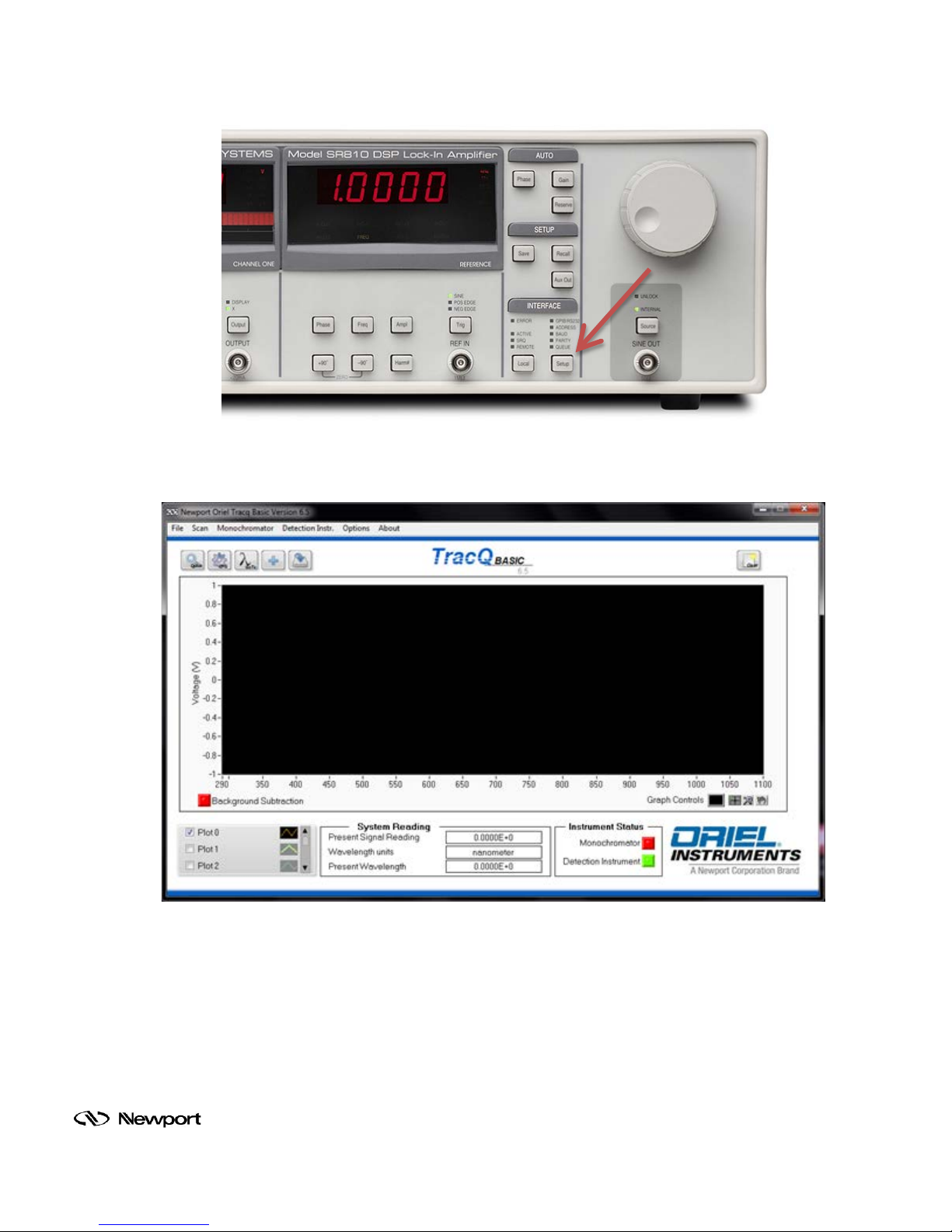
Figure 11: View GPIB Address on SR810
Figure 12: LIDA Communication Established
Family of Brands – ILX Lightwave® • New Focus™ • Ophir® • Corion • Richardson Gratings™ • Spectra-Physics
®
MLIDA, Rev A
Page 19
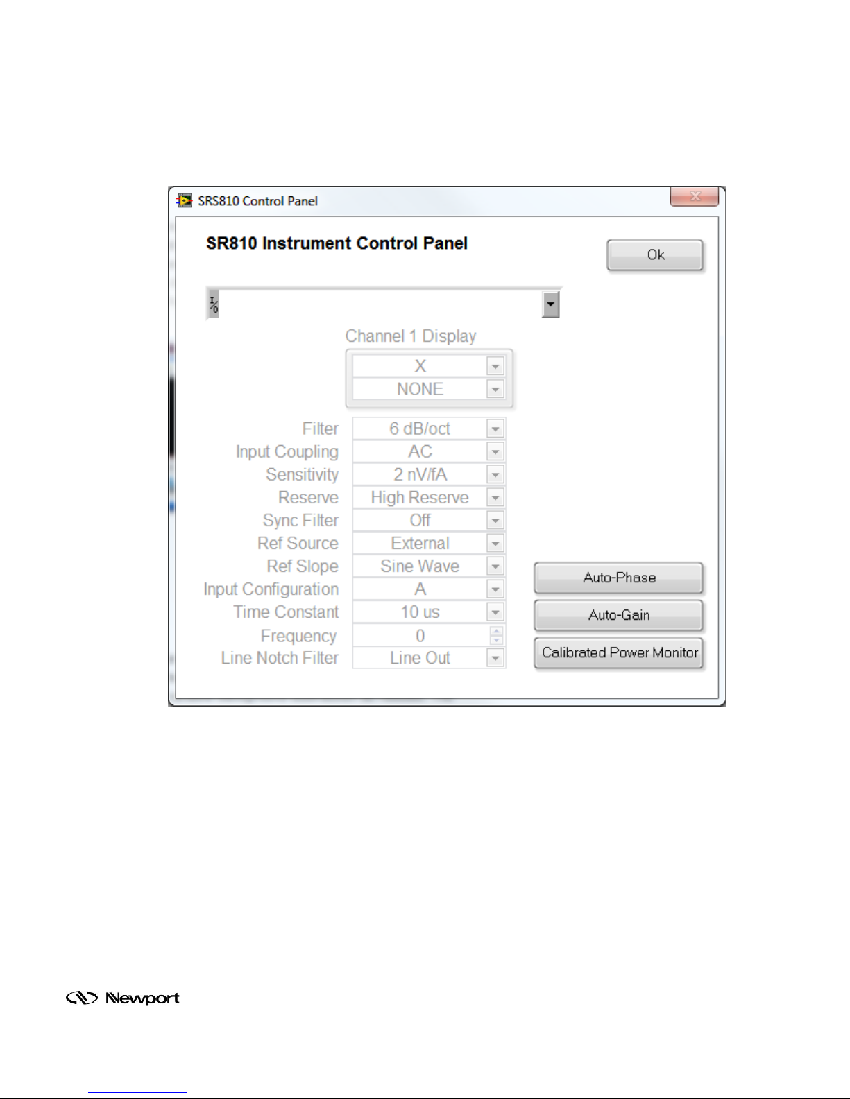
5.2 SETTING OPERATING PARAMETERS
To set the chopping frequency and other operating parameters for the SR810, select Detection
Instr. Setup Parameters .
Figure 13: Setting Operating Parameters in TracQ Basic
Family of Brands – ILX Lightwave® • New Focus™ • Ophir® • Corion • Richardson Gratings™ • Spectra-Physics
®
MLIDA, Rev A
Page 20
6 BASIC OPERATION
6.1 SET INTERNAL FREQUENCY GENERATOR
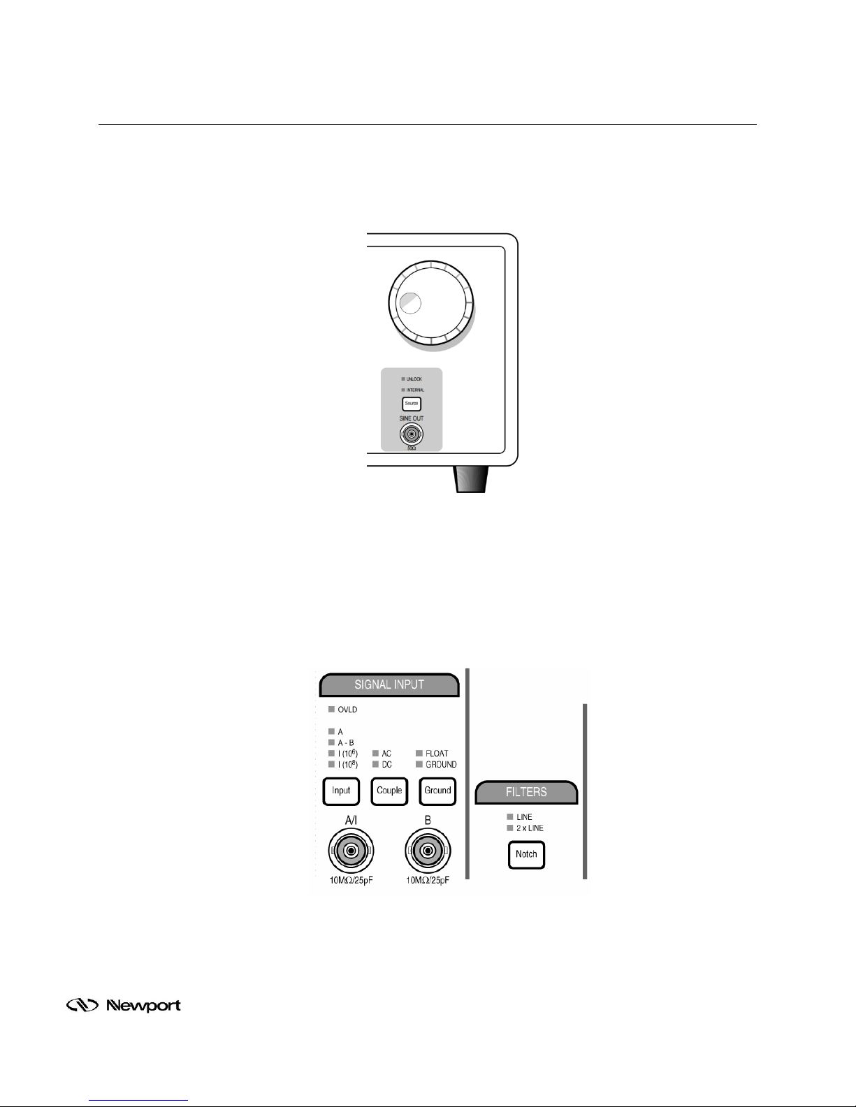
Set the SR810 to lock using the interna l frequency generator b y pressing the SOURCE bu tton on
the front panel of the instrument until the INTERNAL LED is active.
Figure 14: Source Button, SINE out and Frequency Selector Knob
6.2 SET SIGNAL INPUT MODE
Set the SR810 for c urrent m ode operation b y pressing the IN PUT button on the fr ont panel of the
instrument until the I(1 0
Select A or A-B when using amplified detectors with a voltage signal.
6
) or I(108) LED indicator is act ive. T his is used with unamplif ied detec tors.
Figure 15: Signal Input Connecti o n s
Family of Brands – ILX Lightwave® • New Focus™ • Ophir® • Corion • Richardson Gratings™ • Spectra-Physics
®
MLIDA, Rev A
Page 21
6.3 SET AUTO GAI N AN D AUTO PHASE
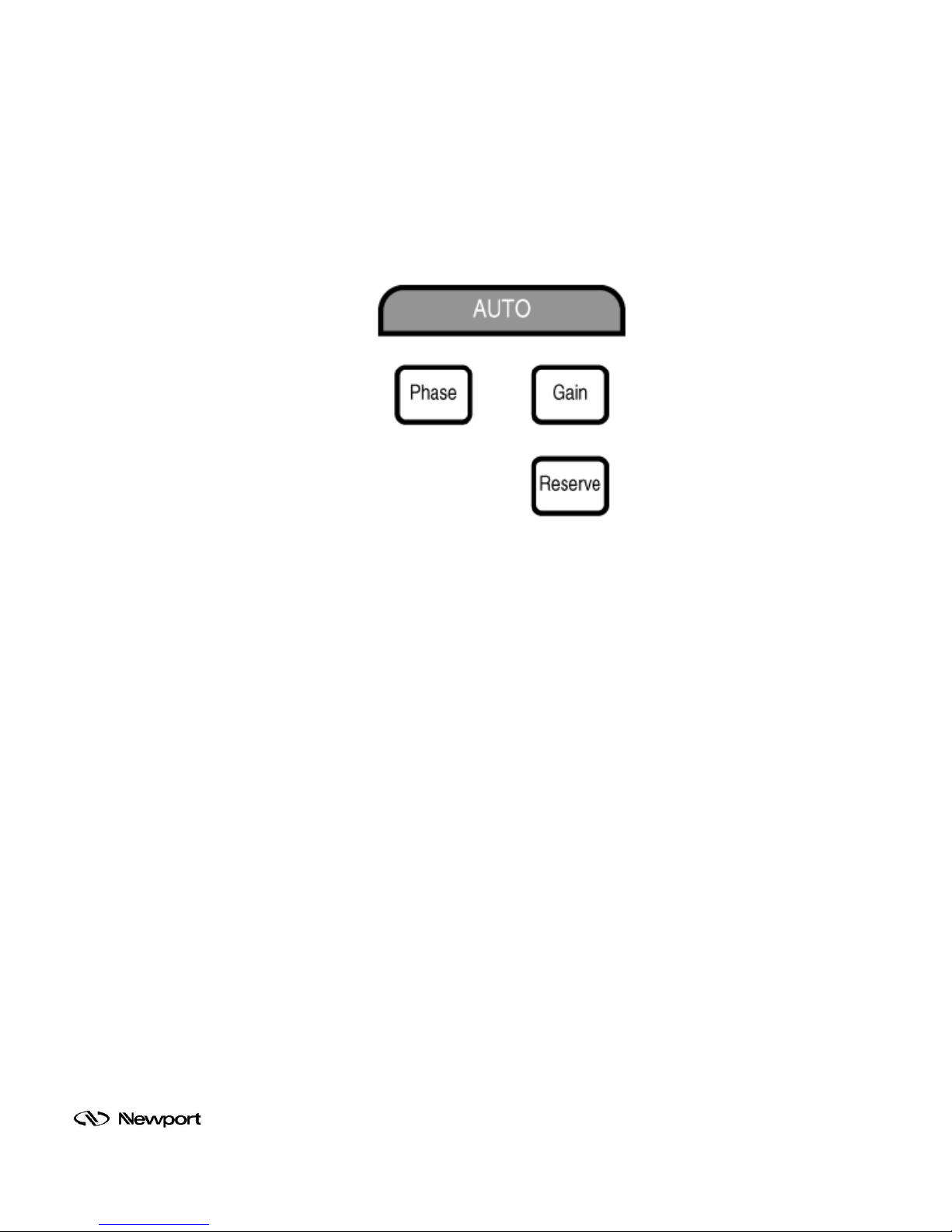
Slowly expose the cov ered detector and ch opper he ad to r oom lighting t aking c are not to o verload
the SR810. You will see a n overload indicator ( OVLD) next to the digita l LED displa y. Press the
AUTOGAIN and AUTO PHASE buttons on the f ront panel of the SR810. T he output LED d isplay
indicator will show the RM S current de tected b y the unam plified detector . If the O VLD indicator is
on after AUTOGAIN was us ed, the signal input is too large, and you must decrease the opt ical
signal on the detector. Please refer to the SR810 User’s Manual for warnings and further details.
Figure 16: Auto Gain and Phase Buttons
Family of Brands – ILX Lightwave® • New Focus™ • Ophir® • Corion • Richardson Gratings™ • Spectra-Physics
®
MLIDA, Rev A
Page 22
7 ADVANCED CONFIGURATIONS AND APPLICATIONS
The SR810 is a powerful instrument with many features. They are described in detail in the user’s
manual provided with the in strum ent. Som e of the m any possible conf igur ations ar e discuss ed here. For
more details, refer to the SR810 user’s manual.
7.1 RATIO MODE SETUP
A reference input correc ts the measurement c hannel to compensate for source drif t. The LIDASRS-KIT system allows you to take readings in a ratio mode by providing a reference channel
input. This serves to improve the ac curacy of response measurements b y removing the s ource
variability.
Any detector type can be utilized for reference if its signal level is compatible with the limited
dynamic range of the ref erence chan nel. T he range is -10.5 V to + 10.5 V and t he resolu tion is 16
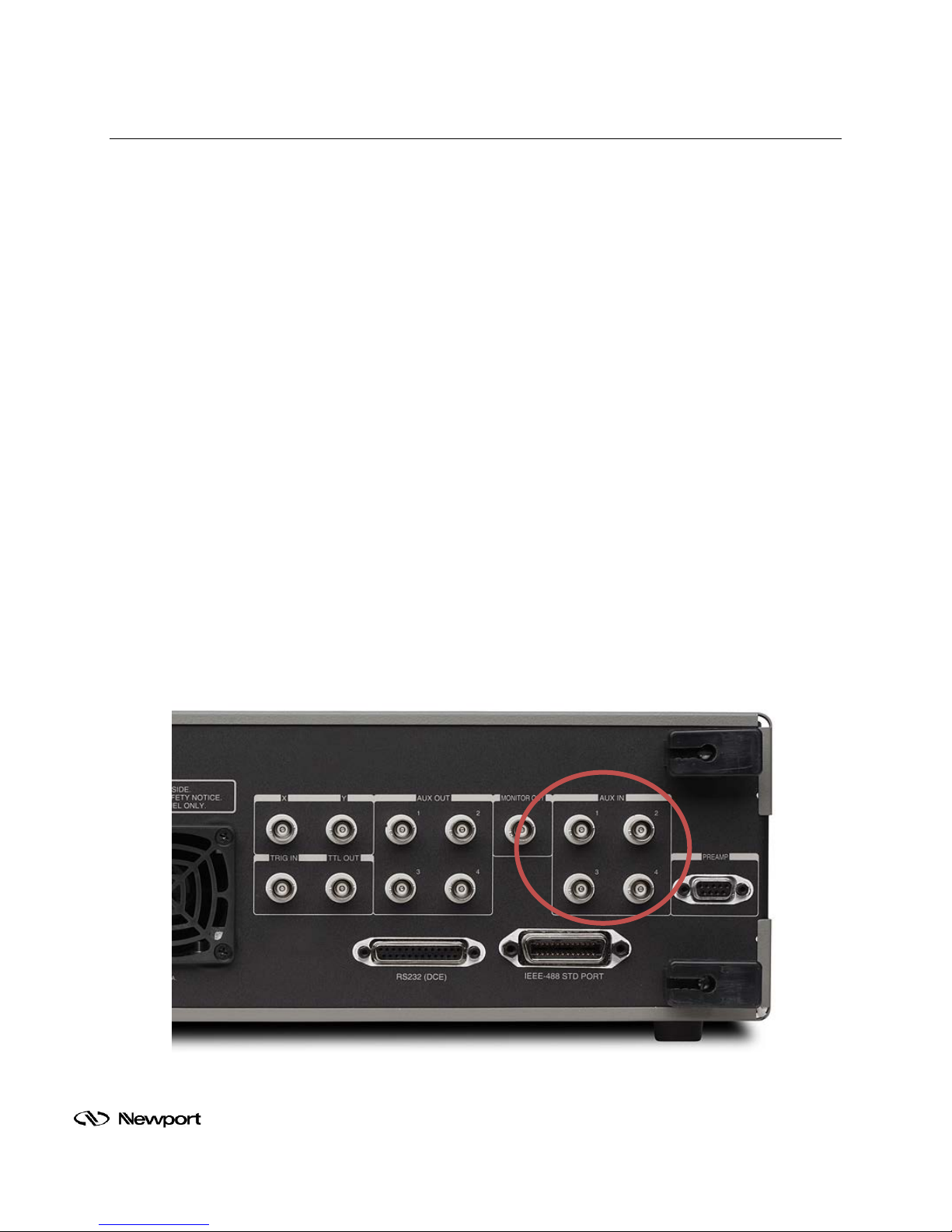
bits (1/3 mV). The input impedance is 1 MΩ. The AUX 1 and 2 inputs on the rear panel of the
SRS SR810 may be displa yed o n the C H1 d is play. These inputs allow s ign als ot her than t he l oc kin outputs to be acquired and stored. Furthermore, ratio quantities, such as X/Aux1, may be
displayed. TracQ Basic can display the ratio quantities. This data is displayed on the SR810
Instrument Control Panel
Items needed to build the setup shown in Figure 19:
• LIDA-SRS-KIT
• Monochromator (example: Oriel model CS260-USB-1-FH-A)
• Amplified, calibrated detector (example: Oriel model DET-L-SIUV-R-C)
• Amplified, uncalibrated detector (example: Oriel model 71883)
• Tunable Light Source, 300W Xenon (Oriel model TLS-300X)
• Beamsplitter (example: Newport model 20B20NC.1)
Family of Brands – ILX Lightwave® • New Focus™ • Ophir® • Corion • Richardson Gratings™ • Spectra-Physics
Figure 17: Reference Connections
®
MLIDA, Rev A
Page 23
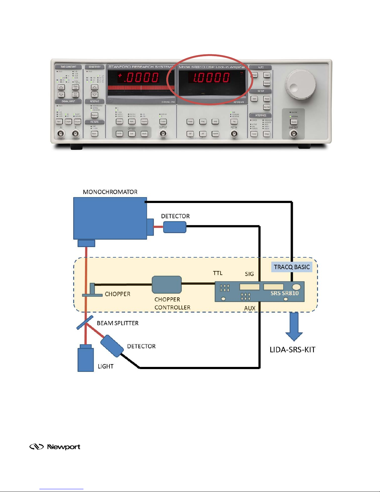
Figure 18: Reference Display
Figure 19: Ratio Measurement Configuration
Family of Brands – ILX Lightwave® • New Focus™ • Ophir® • Corion • Richardson Gratings™ • Spectra-Physics
®
MLIDA, Rev A
Page 24
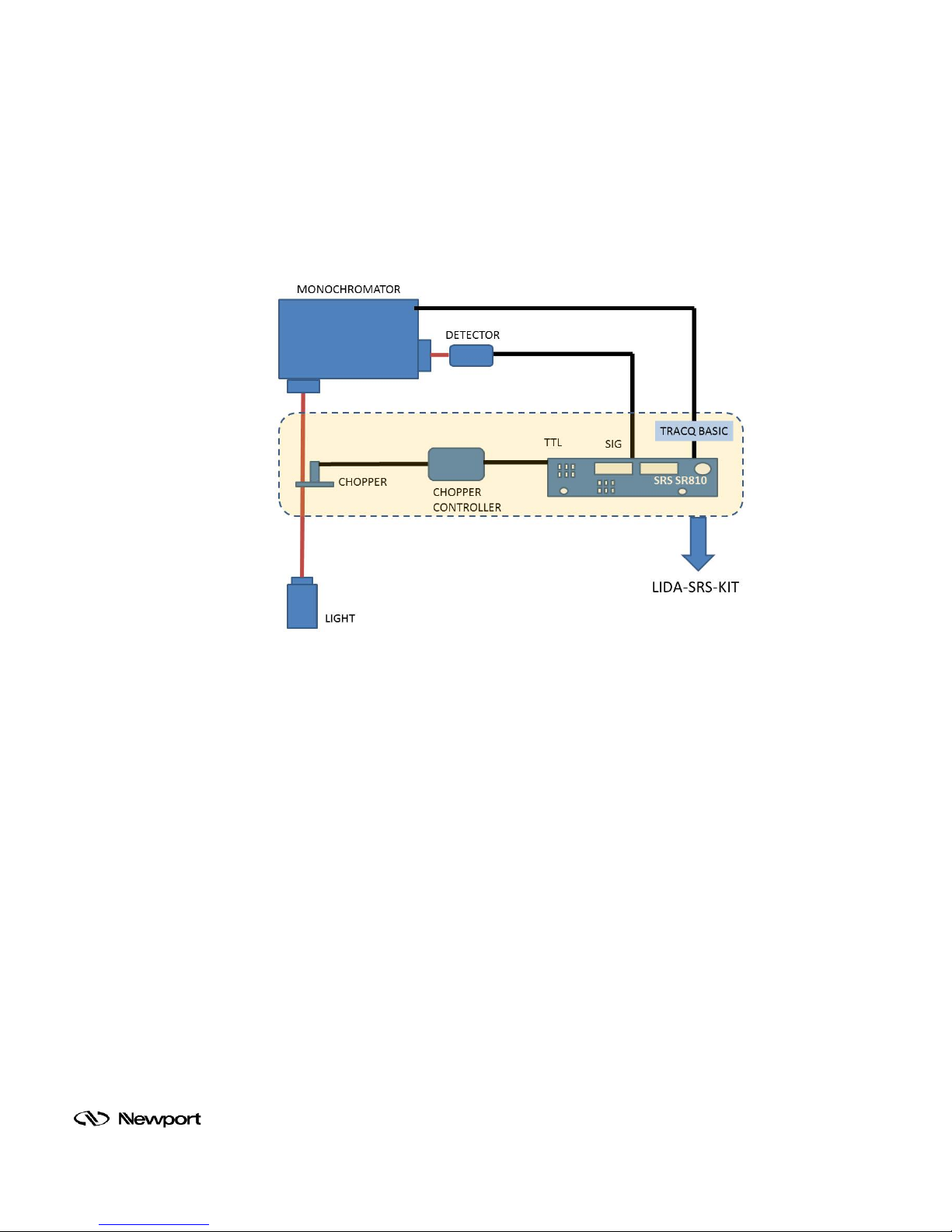
7.2 CALIBRATION
The LIDA-SRS-KIT with T racQ Basic c an display sim ple voltage or curr ent measurem ents as well
as calibrated readings in radiometric units. Most of Oriel’s LIDA-compatible detectors are
available with spectral res ponsivity data. This type of detector can c alculate incid ent power and it
display the readin gs in re al tim e. Figure 20 shows the measur ement s etup of ligh t outp ut from t he
Monochromator.
Figure 20: Oriel Monochromator Integration with TracQ Basic
Items needed to build the setup shown in Figure 20:
• LIDA-SRS-KIT
• Monochromator (example: Oriel model CS260-USB-Q-FH-A)
• Amplified, calibrated detector (example: Oriel model DET-L-SIUV-R-C)
• Tunable Light Source, 300W Xenon (Oriel model TLS-300X)
Because the LIDA-SRS-KIT is com patible with a wide variet y of detectors, the precise proced ure
for obtaining calibr ated r esults vari es . It is typically necessary to load wavelength and respons ivit y
values into one of the wavelength tables, to enter a calibration scale number, and to enter the
wavelength at which the measurement will be tak en. With these three steps, the LID A-SRS-KIT
will display accurate calibrated data in watts.
The Oriel detector model DET -L-SIUV-R-C is calibrated f rom 200 to 1000 nm at room tem perature
and has a 10 x 10 mm square active area. The built-in transimpedance amplifiers allow the gain to
be set from 10
4
V/A to 109 V/A.
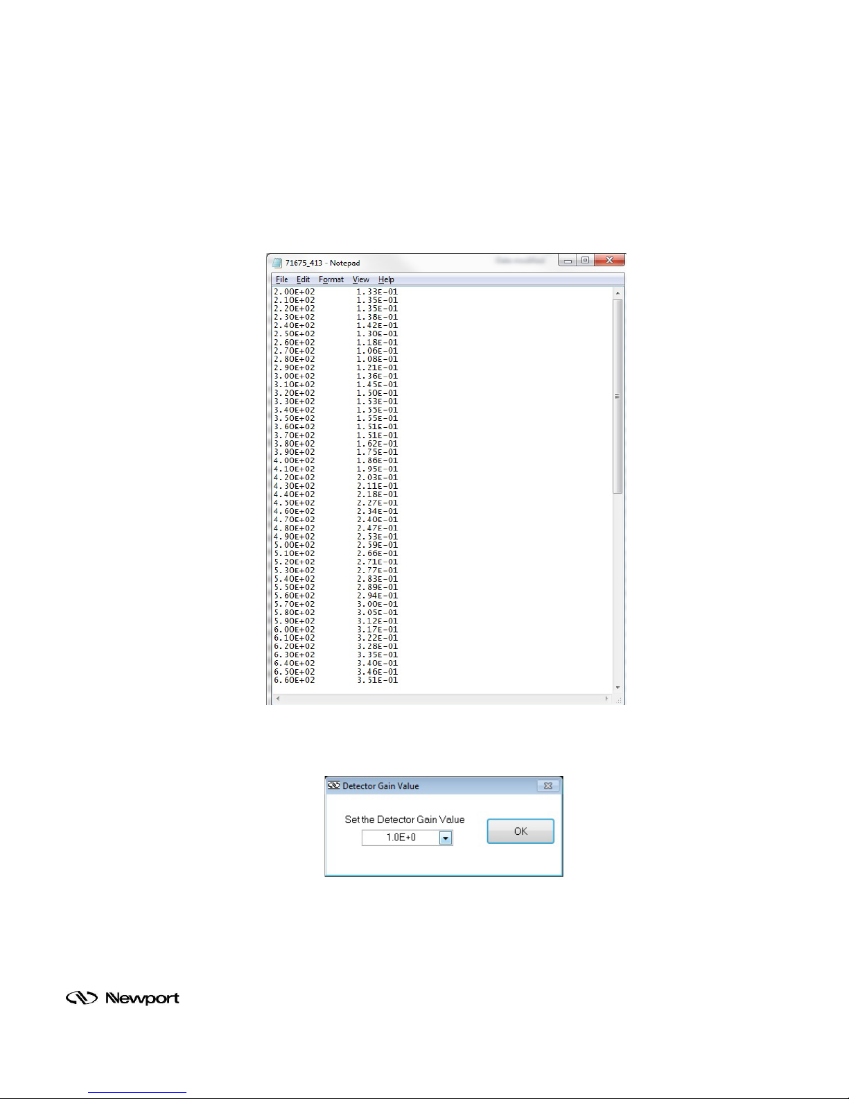
The calibrated data file provi ded with the detector has two columns of tabulated data, wave length
and responsivity, as shown i n Figure 21. After the calibra ted dat a is load ed into Trac Q Basic, t he
detector gain value needs to be entered. The detector gain value must match the gain switch
position on the detector. Figure 22 illustrates the software’s gain setting dialog box.
Family of Brands – ILX Lightwave® • New Focus™ • Ophir® • Corion • Richardson Gratings™ • Spectra-Physics
®
MLIDA, Rev A
Page 25
Prior to taking a detect or radiometry data, the wavelen gth range an wavelength step siz e
(interval) need to be set. Once this information is entered into the software, the detector
radiometry scan allows radiant measurement data to be taken over the detector’s calibrated
wavelength range. For further detailed instructions of calibrated operations, please refer to
the TracQ Basic user’s manual.
Family of Brands – ILX Lightwave® • New Focus™ • Ophir® • Corion • Richardson Gratings™ • Spectra-Physics
Figure 21: Calibrated Detector File
Figure 22: Setting Detector Gain Value
®
MLIDA, Rev A
Page 26
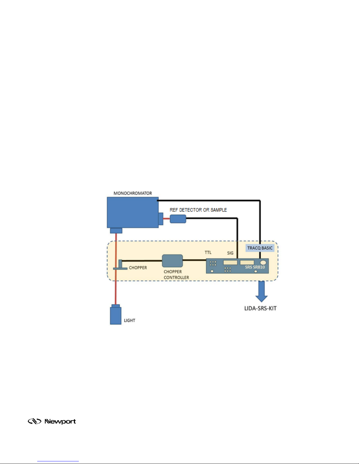
7.3 QUANTUM EFFICIENCY MEASUREMENTS
The LIDA-SRS-KIT allows researchers to measure Quantum Efficiency (QE), also known as
Incident Photon to Charge Carr ier Eff icienc y (IPCE), f or solar ce lls , det ec tors , or an y oth er p hotonto-charge converting device.
TracQ Basic software allows the LIDA-SRS-KIT and Oriel Monochromators to coordinate their
operation in order to obta in QE data. TracQ Basic features built-in QE meas urement functionali ty
which allows signal data from the LIDA-SRS-KIT to be displayed in real time.
Items needed to build the setup shown in Figure 23:
• LIDA-SRS-KIT
• Monochromator (example: Oriel model CS260-USB-Q-FH-A)
• Amplified, calibrated detector (example: Oriel model DET-L-SIUV-R-C)
• Sample solar cell or uncalibrated detector
• Tunable Light Source, 300W Xenon (Oriel model TLS-300X)
Figure 23: QE Measurement Configuration
The user selects the grating and filter changeover wavelengths for the monochromator and
motorized filter wheel. T he SR810 parameters are set up, as well as the scan parameters. A
reference scan of a detec tor or sample with k nown spectral responsivity is take n. This is f ollowed
by a scan of the dev ice for which QE needs to be d etermined. This data is plott ed and can be
saved to a file. T he TracQ Basic user’s manual pro vides further information on perfor ming QE
scans.
Family of Brands – ILX Lightwave® • New Focus™ • Ophir® • Corion • Richardson Gratings™ • Spectra-Physics
®
MLIDA, Rev A
Page 27
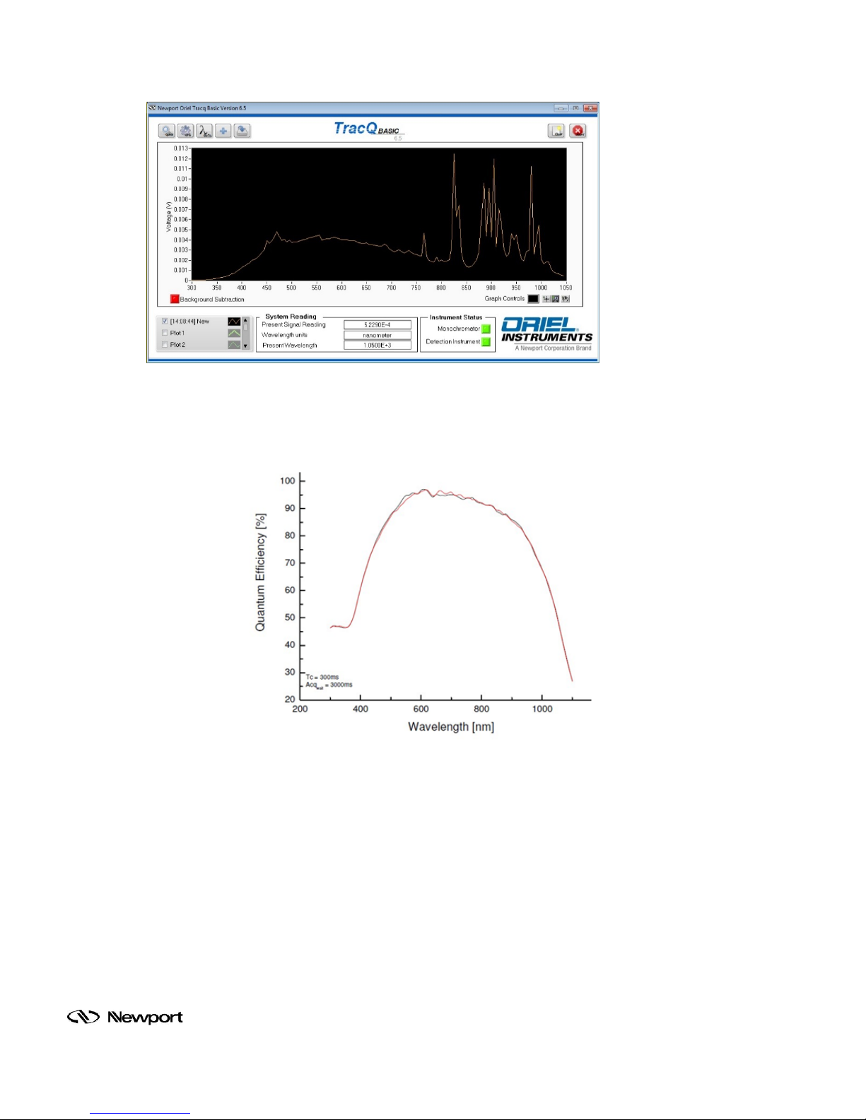
Figure 24: Reference Spectra Measurement Using TracQ Basic
Figure 25: QE Measurements of Samples
Family of Brands – ILX Lightwave® • New Focus™ • Ophir® • Corion • Richardson Gratings™ • Spectra-Physics
®
MLIDA, Rev A
Page 28

8 DETECTORS
Model
Number
8.1 ORIEL LIDA-COMPATIBLE DETECTORS
A broad selection of detectors are compatible with t his system, allowing measurem ent of optical
radiation from UV to IR. Each LIDA de tector includes an integrated amplifier. All m odels except
pyroelectric include a selectable gain switch. T he LIDA detectors include a ll cables necessary to
perform measurements.
Thermoelectricall y cooled detectors include a cable t hat connects to the 77055 Cool er Controller.
A special cable is included with each LIDA detector, providing power from the SR810 to the
integrated detector amplifiers.
Each detector model featur es a 1.5-inch series flange, which is com patible with a wide variety of
Oriel accessories an d ins tr uments. A 1/4-20 threaded hol e is loc at ed o n the bottom of the housing,
allowing the any detector to be rod mounted if desired.
Description
DET-L-SIUV-R-C
DET-L-SIUV-T-C
DET-L-GE-R-C
DET-L-GE-T-C
DET-L-PYC5-R-P
DET-L-PYK5-R-P
UV-enhanced Si photodiode w/transimpedance amplifier, 200-1100 nm
sensitivity, 10 mm x 10 mm active area, NIST traceable calibration
UV-enhanced Si photodiode w/integrated transimpedance amplifier, 2001100 nm sensitivity, 1-stage TE cooled, 5 mm diameter active area, NIST
traceable calibration
Ge photodiode w/integrated transimpedance amplifier, 700-1800 nm
sensitivity, 5 mm diameter active area, NIST traceable calibration
Ge photodiode w/integrated transimpedance amplifier, 700-1800 nm
sensitivity, 2-stage TE cooled, 5 mm diameter active area, NIST traceable
calibration
Lithium tantalate pyroelectric detector w/integrated FET amplifier and high
speed signal processing electronics, 0.45-9 µm sensitivity, 5 mm diameter
active area, NIST traceable calibration
Lithium tantalate pyroelectric detector w/integrated FET amplifier and signal
processing electronics, 0.6-50 µm sensitivity, 5 mm diameter active area,
NIST traceable calibration
DET-L-PBS-R-U
PbS photodiode w/integrated voltage supply and AC coupled pre-amplifier,
0.7-0.3 um sensitivity, 3 mm x 3 mm active area
Family of Brands – ILX Lightwave® • New Focus™ • Ophir® • Corion • Richardson Gratings™ • Spectra-Physics
®
MLIDA, Rev A
Page 29
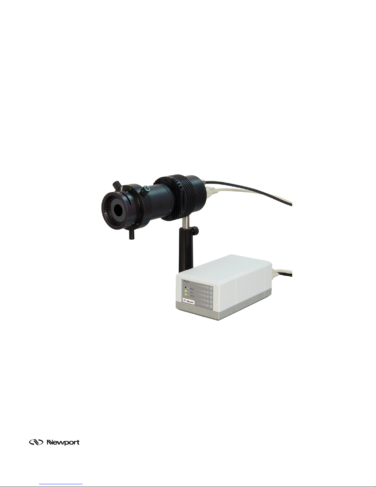
8.2 OTHER DETECTORS
The LIDA system also s upports other detec tors , bot h a mplified and unamplified, with a BNC o utp ut
connector. The 70710 Pr eamplifier, when used with an unamplified detector, conver ts the signal
from current to volt age. This option allo ws users to take advantag e of the LIDA system ’s greater
dynamic range for voltage readings.
Many of Oriel's legac y amplified detec tors may easily be integrated with the LIDA, provided t he
detector has Mini-DIN and BNC connectors. Discard the Mini-DIN connector included with the
legacy detector and rep lace it with cable model CBL-70054-LIDA to provide po wer to the built-in
preamplifier. Add a BNC cable, such as the model 70018, to send the signal output from the
detector to the LIDA.
Oriel’s HgCdZnTe detector s, typically used with the M IR8035 FTIR, m ay be easily integrated with
the LIDA-SRS-KIT. Sim ply discard t he FTIR cable and r eplace with a BNC cab le, then conn ect to
the SR810.
Family of Brands – ILX Lightwave® • New Focus™ • Ophir® • Corion • Richardson Gratings™ • Spectra-Physics
Figure 26: Oriel HgCdZnTe Detector
®
MLIDA, Rev A
Page 30
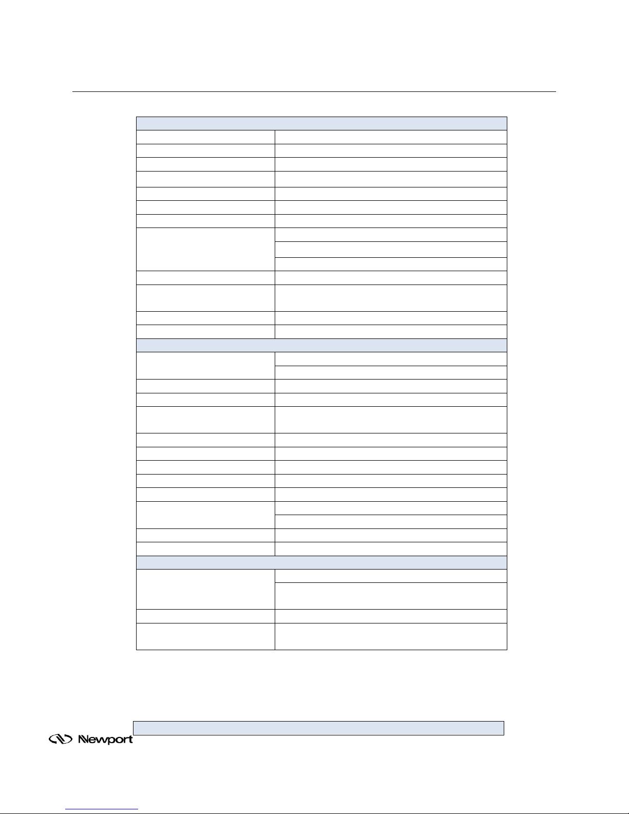
9 SPECIFICATIONS
SIGNAL
CHANNEL
Number of Detector Channels 1
Voltage Inputs
Single-ended or differential
Sensitivity 2 nV to 1 V
Voltage Input Impedance
10 MΩ + 25 pF, AC or DC coupled
Current Input Impedance
1 kΩ to virtual ground
Gain accuracy
±1% (±0.2%
typ.)
6 nV/√Hz at 1
kHz
0.013 pA/√Hz at 100 kHz (108 V/A)
Line
Filters
50/60 Hz and 100/120 Hz (Q=4)
Common Mode
Rejection
Ratio
100 dB at 10 kHz, decreasing by 6 dB/oct above 10
kHz
Dynamic Reserve
>100 dB (without prefilters)
Stability <5
ppm/°C
REFERENCE
CHANNEL
0.001 Hz to 102.4 kHz
hopper wheel dependent
Reference Input
TTL or sine (400 mVpp min.)
Input Impedance
1 MΩ, 25 pF
0.01° front panel, 0.008° through computer
interfaces
Absolute Phase Error
<1°
Relative Phase Error
<0.001°
Orthogonality
90° ±
0.001°
Int. Reference Phase Noise
Synthesized, <0.0001° rms at 1 kHz
Ext. Reference Phase Noise
0.005° rms at 1 kHz, 100 ms, 12 dB/oct
<0.01°/°C below 10 kHz
<0.1°/°C, 10 kHz to 100 kHz
Harmonic Detection
2F, 3F, ... nF to 102 kHz (n < 19,999)
Acquisition Time
(2 cycles + 5 ms) or 40 ms, whichever is greater
DEMODULATOR
Digital outputs and display: no drift.
Harmonic Rejection
-90 dB
Synchronous filters available below 200 Hz.
INTERNAL
OSCILLATOR
Current Input 106 or 108 V/A
Noise
0.13 pA/√Hz at 1 kHz (106 V/A)
Frequency Range
Phase Resolution
Phase
Stability
Time Constants
Family of Brands – ILX Lightwave® • New Focus™ • Ophir® • Corion • Richardson Gratings™ • Spectra-Physics
Drift
Analog outputs: <5 ppm/°C for all dynamic reserve
settings.
10 µs to 30 ks (6, 12, 18, 24, dB/oct roll off).
®
MLIDA, Rev A
Page 31
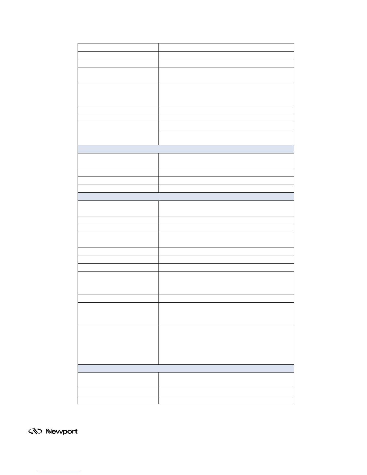
Range 1 MHz to 102
kHz
Accuracy 25 ppm + 30
µHz
Frequency Resolution
4-1/2 digits or 0.1 MHz, whichever is greater
Distortion
-80 dBc (f<10 kHz), -70 dBc (f> 10 kHz) @ 1 Vrms
amplitude
0.004 to 5 Vrms into 10 kΩ (2 mV resolution), 50 Ω
Amplitude Accuracy 1%
Amplitude Stability
50
ppm/°C
Sine,
TTL
DISPLAYS
±10 V output of X, R, X-noise, Aux 1 or Aux 2.
Updated at 512
Hz.
Offset
X, Y, R can be offset up to ±105% of full scale
Expand
X, Y, R can be expanded by 10x or 100x
Reference
4-1/2 digit LED display
INPUTS AND
OUTPUTS
X, Y Outputs
In-phase and quadrature components
(rear panel)
(±10 V), updated at 256 kHz
4 BNC inputs, ±10 V, 1 mV resolution, sampled at
512 Hz
Aux. D/A Outputs
4 BNC outputs, ±10 V, 1 mV resolution
Sine
Out
Internal oscillator analog output
TTL
Out
Internal oscillator TTL output
Trigger In (TTL)
Trigger synchronizes data recording
Provides power to the preamplifier integrated
inside
GENERAL
Dimensions
17" W x 5.25" H x 19.5" L [431 x 133 x 495 mm]
Weight 30 lbs [13.6
kg]
Amplitude
Outputs
Channel 1 Output
Channel 1 Output
Aux. A/D Inputs
output impedance, 50 mA maximum current into 50
Ω
When using an external reference, both outputs are
phase locked to the external reference.
2.
±10 V output of X, R, X-noise, Aux 1 or Aux
Updated at 512
Hz.
Data Buffer
Remote Pre-amp
Computer Interface
Power
Family of Brands – ILX Lightwave® • New Focus™ • Ophir® • Corion • Richardson Gratings™ • Spectra-Physics
8k point buffer with data recorded at rates to 512 Hz
and read through the computer interfaces.
Oriel's LIDA detectors, using cable Model
70054-LIDA
IEEE-488.2 and RS-232 interfaces standard.
instrument functions can be controlled and
through IEEE-488.2 or RS-232 interfaces. TracQ
software utilizes GPIB
100 to 120 VAC, 220 to 240 VAC, 50 to 60 Hz, 40 W
MLIDA, Rev A
communication.
CBL-
All
read
Basic
®
Page 32

10 W ARRANTY AND SERVICE
10.1 CONTACTING NEW PORT CORPORATION
Oriel Instruments belongs to Newport Corporation's family of brands. Thanks to a steadfast
commitment to qualit y, inn o vat ion , hard w ork and customer care, Newpor t is trus te d the w orld ov er
as the complete source for all photonics and laser technology and equipment.
Founded in 1969, Newport is a pioneer ing single-sour ce solutions provider of las er and photonics
components to the leaders in scientific research, life and health sciences, photovoltaics,
microelectronics, industrial manufacturing and homeland security markets.
Newport Corporation proudly serves customers across Canada, Europe, Asia and the United
States through numer ous international subsidiaries and sales off ices worldwide. Every year, the
Newport Resource catalog is hailed as the premier sourcebook for those in need of advanced
technology products a nd services. It is available by m ail request or through Newport's webs ite.
The website is where one will find product updates, interactive demonstrations, specification charts
and more.
To obtain information regarding sales, technical support or factory service, United States and
Canadian customers should contact Newport Corporation directly.
Newport - Oriel Instruments
1791 Deere Avenue
Irvine, CA 92606 USA
Telephone: 800-222-6440 (toll-free in United States)
Technical assistance: [email protected]
Repair Service: [email protected]
Customers outside of the United States must contact their regional representative for all sales,
technical support and service inquiries. A list of worldwide representatives can be found on the
following website: http://www.newport.com/oriel
.
Family of Brands – ILX Lightwave® • New Focus™ • Ophir® • Corion • Richardson Gratings™ • Spectra-Physics
®
MLIDA, Rev A
Page 33

10.2 REQUEST FOR ASSISTANCE / SERVICE
Please have the following information available when requesting assistance or service:
Contact information for the owner of the product.
Instrument model number (located on the produc t la bel ).
Product serial number and date of manufacture (located on the product label).
Description of the problem.
To help Newport’s Technical Support Representatives diagnose the problem, please note the
following:
Is the system used for manufacturing or research and development?
What was the state of the system right before the problem?
Had this problem occurred before? If so, when and how frequently?
Can the system continue to operate with this problem, or is it non-operational?
Were there any differences in the application or environment before the problem occurred?
10.3 REPAIR SERVICE
This section contains information regarding factor y service for this product. The us er should not
attempt any maintenance o r service of the s ystem beyond the procedures out lined in this manual.
This product contains no user serviceable parts other than what is noted in this manual. Any
problem that cannot be resolved should be referred to Newport Corporation.
If the instrument needs to be retur ned for service, a Return Ma terial Authorization (RMA) num ber
must be obtained prior to shipment to Newport. This RMA number must appear on both the
shipping container and the package documents.
Return the product to Ne wport, freight prepa id, clearly mark ed with the RMA num ber and it either
will be repaired or replaced it at Newport's discretion.
Newport is not responsible for damage occurring in transit. The Owner of the product bears all risk
of loss or damage to the returned Products until delivery at Newport’s facility. Newport is not
responsible for product da mage once it has left the facility after repair or replacem ent has been
completed.
Newport is not obligated to accept products returned without an RMA number. Any return
shipment received by Newport without an RMA number may be reshipped by Newport, freight
collect, to the Owner of the product.
10.4 NON-WARRANTY REPAIR
For Products returne d for repair that are not co vered under warrant y, Newport's standard repair
charges shall be applicable in addition to all shipping expenses. Unless otherwise stated in
Newport's repair quote, a ny such out-of-war ranty repairs are warr anted for ninety (90) da ys from
date of shipment of the repaired Product.
Newport will charge an evaluation fee to examine the product and determine the most appropriate
course of action. Payment information must be obtained prior to having an RMA number
assigned. Custom ers may use a valid credit card, and those who have an exis ting account with
Newport Corporation may use a purchase order.
When the evaluation had b een com pleted, t he owner of the pr oduct will b e conta cted and n otified
of the final cost to repair or replace the item. If the decision is made to not proceed with the
Family of Brands – ILX Lightwave® • New Focus™ • Ophir® • Corion • Richardson Gratings™ • Spectra-Physics
MLIDA, Rev A
®
Page 34

repair, only the evaluatio n fee will be billed. If authorization to perform the repair or pr ovide a
replacement is obtain ed, the evaluation f ee will be applied to the final cost. A revised purchase
order must be subm itted for the f inal cost. If pa ying by cred it card, writt en author ization must be
provided that will allow the full repair cost to be charged to the card.
10.5 WARRANTY REPAIR
If there are any defects in material or workmanship or a failure to meet specifications, notify
Newport Corporation promptly, prior to the expiration of the warranty.
Except as otherwise expressly stated in Newport’s quote or in the current operating manual or
other written guarant ee for any of the Products, N ewport warrants that, for the period of time set
forth below with respect to each Product or c omponent t ype (the "W arranty Period"), th e Products
sold hereunder will be free from defects in material and workmanship, and will conform to the
applicable specificati ons, under normal use an d service when correctl y installed and maintained.
Newport shall repair or r eplace, at Ne wport's sole opti on, any defec tive or nonconf orming Product
or part thereof which is returned at Buyer's expense to Newport’s facility, provided, that Buyer
notifies Newport in writing pr omptly after discovery of the defect or nonconf ormity and within the
Warranty Period. Products may only be returned b y Buyer when ac com panied b y a return m aterial
authorization num ber ("RMA number") iss ued by Newport, with freight prepaid b y Buyer. Newport
shall not be responsible for any damage occurring in transit or obligated to accept Products
returned for warranty repair without an RM A number. The buyer bear s a ll risk of loss or damage to
the Products until deliver y at Newport’s facility. Ne wport shall pay for shipment back to Buyer for
Products repaired under warranty.
WARRANTY PERIO D
All Products (except c onsumables s uch as lamps, f ilters, etc.) descr ibed here are warrante d for a
period of twelve (12) months from the date of shipment or 3000 hours of operation, whichever
comes first.
Lamps, gratings, optical filters and other consumables / spare parts (whether sold as separate
Products or constituti ng components of other Produc ts) are warranted for a per iod of ninety (90)
days from the date of shipment.
WARRANTY EXCLUSIONS
The above warrant y does n ot appl y to Produc ts which are (a) re paired, m odified o r altered by an y
party other than Newport; (b) used in conjunction with equipment not pro vided or authorized by
Newport; (c) subjected to unusual physical, thermal, or electrical stress, improper installation,
misuse, abuse, accident or negligence in use, storage, transportation or handling, alteration, or
tampering, or (d) consid ered a consum able item or an item requiring repa ir or replacem ent due to
normal wear and tear.
Family of Brands – ILX Lightwave® • New Focus™ • Ophir® • Corion • Richardson Gratings™ • Spectra-Physics
®
MLIDA, Rev A
Page 35

DISCLAIMER OF WARRANTIES; EXCLUSIVE REMEDY
THE FOREGOIN G WARRANTY IS EXCLUSIVE A ND IN LIEU OF ALL OTHER W ARRANTIES.
EXCEPT AS EXPRESSLY PROVIDED HEREIN, NEWPORT MAKES NO WARRANTIES,
EITHER EXPRE SS OR I M PLIED , EIT HER IN FAC T O R BY OP ER ATI ON O F LAW , ST ATUT ORY
OR OTHERWISE, REGARDING THE PRODUCTS, SOFTWARE OR SERVICES. NEWPORT
EXPRESSLY DI SCLAIMS ANY IMPLIED WARRANTIES OF MER CHANTABILITY OR FI TNESS
FOR A PARTICULAR PURPOSE FOR THE PRODUCTS, SOFTWARE OR SERVICES. THE
OBLIGATIONS O F NEWPORT SET FORTH IN THIS SECT ION SHALL BE NEW PORT'S SOLE
LIABILITY, AND BUYER'S SOLE REMEDY, FOR BREACH OF THE FOREGOING
WARRANTY. Representations and warranties m ade by any person including dis tributors, dealers
and representatives of Newport Corporation which ar e inconsistent or in conflict with the terms of
this warranty shall not be binding on Newport unless reduced to writing and approved by an
expressly an authorized officer of Newport.
10.6 LOANER / DEMO MATERIAL
Persons receiving goods f or demonstrations or tem porary use or in any m anner in wh ich ti tle is not
transferred from Newport shall assume full responsibility for any and all damage while in their care,
custody and control. If damage occurs, unrelated to the proper and warranted use and
performance of the g oods, rec ipient of the goods accepts f ull respons ibilit y for restoring the goods
to their original condition upon delivery, and for assuming all costs and charges.
Confidentiality & Proprietary Rights
Reservation of Title:
The Newport programs and all materials furnished or produced in connection with them ("Related Materials") contain trade secrets
of Newport and are for use only in the manner expressly permitted. Newport claims and reserves all rights and benefits afforded
under law in the Programs provided by Newport Corporation.
Newport shall retain full ownership of Intellectual Property Rights in and to all development, process, align or assembly technologies
developed and other derivative work that may be developed by Newport. Customer shall not challenge, or cause any third party to
challenge the rights of Newport.
Preservation of Secrecy and Confidentiality and Restrictions to Access:
Customer shall protect the Newport P rogram s and Related Materials as trade secr ets of Newport, and shall devote its best efforts to
ensure that all its personnel prot ect the Newport Program s as t rade sec rets of Newport Corpor ati on. Cust omer s hall not at any time
disclose Newport's trade secrets to any other person, firm, organization, or employee that does not need (consistent with
Customer's right of use hereunder) to obtain access to the Newport P rograms and Related Materials. These restrictions shall not
apply to information (1) generally known to t he public or obtainable from public sourc es; (2) readily apparent from the keyboard
operations, visual display, or output reports of the Programs; 3) previously in the possession of Customer or subsequently
developed or acquired without reliance on the Newport Programs; or (4) approved by Newport for release without restriction.
First printing 2015
© 2015 by Newport Corporation, Irvine, CA. All rights reserved.
No part of this manual may be reproduced or copied without the prior written approval of Newport Corporation.
This manual has been provided for information only and product specifications are subject to change without notice.
Any change will be reflected in future printings.
Newport Corporation 1791 Deere Avenue Irvine, CA, 92606 USA
Family of Brands – ILX Lightwave® • New Focus™ • Ophir® • Corion • Richardson Gratings™ • Spectra-Physics
®
MLIDA, Rev A
 Loading...