

Oridion Capnostream 20p Owner's Manual

Capnostream®20p
Portable Bedside Monitor
Capnograph/Pulse Oximeter
Operator’s Manual
PN: 012194C
0482

Notice: Purchase of this product confers no express or implied license under any Oridion Medical 1987 Ltd.
patent to use the instrument with any accessory that is not manufactured or licensed by Oridion Medical 1987
Ltd.
Possession or purchase of this device does not convey an express or implied license to use the device with
unauthorized sensors or cables which would, alone, or in combination with this device, fall within the scope of
one or more of the patents relating to this device.
®
Oridion
CapnoBloc™, Smart CapnoLine Guardian™, SARA™, Integrated Pulmonary Index™, Capnostream
Microcap
, Microstream®, FilterLine, Smart CapnoLine®, CapnoLine®, Smart BiteBloc™, NIV Line™,
®
, Microcap® Plus, and VitalC ap® are trademarks or registered trademarks of Oridion Medical 1987
Ltd.
Nellcor Puritan Bennett LLC is a Covidien company.
The following are trademarks of Nellcor Puritan Bennett LLC: Oxiband™; Durasensor™; OxiCliq
Max-Fast™ and O
XIMAX™.
®
; Dura-Y™;
The capnography component of this product is covered by: US Patents: www.covidien.com/patents.
The pulse oximetry component of this product is covered by: US Patents: www.covidien.com/patents.
Exemptions
Oridion Medical 1987 Ltd.'s liability under this warranty does not include any transportation damage or other
charges or liability for direct, indirect or consequential damages or delay resulting from improper use or
application of the product or the substitution upon it of parts or accessories not approved by Oridion Medical
1987 Ltd.
All information in this manua l is believed to be corre ct. Oridion Medical 1987 Ltd. shall not be liable for errors
contained herein with the performance or use of this manual.
Copyright © 2014 Oridion Medical 1987 Ltd. All rights reserved.
®
20p,

Portable Bedside Capnograph/Pulse Oximeter
1
Table of Contents
Table of Contents 1
List of Figures 8
List of Tables 9
Oridion Medical 1987 Ltd. ("Oridion Medical") - Warranty for
Oridion Monitors 10
Safety Information 11
Warnings ....................................................................................................................... 11
General ....................................................................................................................................... 11
MRI Scanning ............................................................................................................................. 12
Monitor Use with Defibrillators ................................................................................................... 12
Alarms ........................................................................................................................................ 12
Fire Hazard................................................................................................................................. 12
Electrical ..................................................................................................................................... 13
Electro-magnetic Interference .................................................................................................... 13
Definitions ..................................................................................................................... 14
Chapter 1 15
About this Manual 15
Overview ....................................................................................................................... 15
Intended Use ................................................................................................................. 15
Specific Indications for Use ........................................................................................... 16
Who Should Read This Manual ..................................................................................... 16
Contacting Technical S upp or t ....................................................................................... 16
Symbols ........................................................................................................................ 16
Chapter 2 19
Technology Overview 19
Introduction ................................................................................................................... 19
Features ........................................................................................................................ 19
Technology Overview .................................................................................................... 19
What is Capnography? .............................................................................................................. 19
What is Pulse Oximetry? ............................................................................................................ 20
Chapter 3 21
The Capnostream Monitor 21
Unpacking and Inspection ............................................................................................. 21
Installing the Battery Pack ............................................................................................. 22
Testing the Battery and A C Connections................................................................................... 23
Handling the Battery Pac k ......................................................................................................... 23

2
Portable Bedside Capnograph/Pulse Oximeter
Storing the Battery ..................................................................................................................... 24
Disposing of the Battery ............................................................................................................. 24
Battery and Power Usage .......................................................................................................... 24
Mounting the Monitor..................................................................................................... 25
Setting up Periodic Maintenance ................................................................................... 25
Accessories ................................................................................................................... 25
Available Accessories ................................................................................................................ 25
Monitor Mounting Plate .............................................................................................................. 26
Printer Paper .............................................................................................................................. 26
Buttons, Indicators and Connections ............................................................................. 26
Monitor Front View ..................................................................................................................... 27
Front Panel Control Buttons .......................................................................................... 28
Monitor Rear Panel .................................................................................................................... 29
Monitor Left and Right Views ..................................................................................................... 30
Turning on the Monitor .................................................................................................. 30
Standard Sections of the Display Screen ...................................................................... 31
Home Screen Standard D isplay ................................................................................................. 32
Home Screen Numeric Di splay .................................................................................................. 36
Terminating Operation of the Monitor ............................................................................ 37
Screen Navigation ......................................................................................................... 37
Configuration Changes .............................................................................................................. 38
Setting Date, Time, Language, and Other Options ....................................................... 38
Screen Timeouts ........................................................................................................... 39
Screen Timeouts ........................................................................................................................ 39
Capnostream®20p: Operational Check Sheet ................................................................ 40
Chapter 4 43
Using the Capnostream Monitor 43
Preparing the Monitor for a Patient ............................................................................... 43
Setting the Patient Type ............................................................................................................. 43
Using Patient Cases and Patient ID Numbers ............................................................... 44
Entering Patient Events ................................................................................................. 46
Changing the Alarm and Pulse Volumes ....................................................................... 46
Alarm Volume ............................................................................................................................. 46
Pulse Tone Volume .................................................................................................................... 47
Alarm Volume Default Options ................................................................................................... 47
Alarm Delay ................................................................................................................... 48
Use of Scavenging System ........................................................................................... 48
Turning the Pump Off for Suction or Lava ge ................................................................. 48
Demo Mode ................................................................................................................... 49
Monitor Screen Menu Reference Chart ......................................................................... 49

Portable Bedside Capnograph/Pulse Oximeter
3
Chapter 5 53
Capnography with the Capnostream Monitor 53
Microstream® EtCO2 Consumables ............................................................................... 53
Basic Principles .......................................................................................................................... 53
Microstream® EtCO2 Consumables ........................................................................................... 54
Connecting a FilterLin e ................................................................................................. 54
CO2 Data Displayed by the Capnostream Monitor ........................................................ 54
Adjustable CO2 Parameters .......................................................................................... 55
Monitoring CO2 during MRI Scannin g ........................................................................... 56
Chapter 6 57
Pulse Oximetry with the Capnostream Monitor 57
Nellcor SpO2 Sensors ................................................................................................... 57
Data Update Period, Data Averaging, and Signal Processing .................................................. 58
Selecting Nellcor SpO2 Sensors ................................................................................................ 58
Performance Consideratio ns ..................................................................................................... 59
Connecting an SpO2 Sensor to the Monitor................................................................... 60
SpO2 Data Displayed by the Capnostream Monitor ...................................................... 60
Adjustable SpO2 Parameters......................................................................................... 62
SPO2 Alarm Limit Message ........................................................................................... 62
Chapter 7 63
Integrated Pulmonary Index™ 63
Introduction ................................................................................................................... 63
Warnings ....................................................................................................................... 64
IPI Display ..................................................................................................................... 64
IPI Options .................................................................................................................... 64
Chapter 8 65
Apneas per Hour and the Oxygen Desaturation Index 65
Introduction ................................................................................................................... 65
Apneas per Hour ........................................................................................................... 65
The Capnostream Apneas per Hour .......................................................................................... 65
A/hr Visual Alert ......................................................................................................................... 66
Oxygen Desaturation Index (ODI) ................................................................................. 66
Apnea and O2 Desaturation Report .............................................................................. 66
Monitoring with A/hr and ODI ........................................................................................ 66
Smart A/hr and ODI Home Screen Display ................................................................... 67
A/hr and ODI Option ...................................................................................................... 67
A/hr and ODI Demo Mode ............................................................................................. 67

4
Portable Bedside Capnograph/Pulse Oximeter
Chapter 9 69
Alarms and Messages 69
Introduction ................................................................................................................... 69
Alarm Display ................................................................................................................ 70
Message Priorities ......................................................................................................... 72
Alarm Delay ................................................................................................................... 72
Types of Alarms ............................................................................................................ 72
High Priority Alarms ................................................................................................................... 73
Medium Priority Alarms .............................................................................................................. 74
Advisories ................................................................................................................................... 75
Silent Advisories ......................................................................................................................... 75
Parameter Standby Mode ............................................................................................. 76
Alarm Silence ................................................................................................................ 78
Changing Alarm Limits .................................................................................................. 79
Testing Alarm Settings .................................................................................................. 80
SpO2 Alarms and SatSecon ds ...................................................................................... 80
SatSeconds Alarm Display ........................................................................................................ 81
Alarm Limits - Factory Defaults ..................................................................................... 82
Chapter 10 83
Using Trends 83
Introduction ................................................................................................................... 83
The Trend Display Screens ........................................................................................... 84
Graphical Trend Display Screen ................................................................................... 84
Graphical Trend Display............................................................................................................. 84
Using SCROLL and ZOOM ........................................................................................................ 85
Tabular Trend Display Screen ....................................................................................... 87
Choosing Trend Parameters ......................................................................................... 89
Important Notes Regarding Trend Reports ................................................................... 89
Specific Events as seen in Trend Data.......................................................................... 89
Using the Graphical Trend Screen for Monitoring Patients ........................................... 89
Printing the Trend Data ................................................................................................. 89
Clearing Trend Memory ................................................................................................. 90
Configuring Trends ........................................................................................................ 90
Event Marking Mode .................................................................................................................. 91
Trend Graphical Display ............................................................................................................. 91
Trend Increment Display ............................................................................................................ 91
Chapter 11 93
Reports 93
Apnea and O2 Desaturation Report ............................................................................... 93
Printed Report Options .................................................................................................. 97
Printed Reports ............................................................................................................. 97

Portable Bedside Capnograph/Pulse Oximeter
5
Sample Reports........................................................................................................... 101
Sample Case Reports .............................................................................................................. 101
Sample Trend Reports ............................................................................................................. 102
Chapter 12 103
Downloading Patient Data 103
Introduction ................................................................................................................. 103
Data Transfer via the USB Data Port .......................................................................... 103
USB File Naming Convention .................................................................................................. 106
Examples .................................................................................................................................. 106
USB Error Messages ............................................................................................................... 107
Reading Patient Data from Saved Capnostream F il es ............................................................ 107
Data Transfer via the RS-232 Port .............................................................................. 107
Analog Data Output with Capnostream ....................................................................... 107
Nurse Call Operation ................................................................................................... 107
Types of Nurse Call Systems ...................................................................................... 108
The Nurse Call Ca ble ............................................................................................................... 108
Activating Nurse Call ................................................................................................................ 109
Testing Nurse Call .................................................................................................................... 109
Operation with Hospital Patient Data Systems ............................................................ 110
Operation with Nuvon VEGA Sys tems ........................................................................ 110
Chapter 13 111
Maintenance and Troubleshooting 111
Introduction ................................................................................................................. 111
Determining Monitor Service Hours ............................................................................. 111
CO2 Calibration ........................................................................................................... 112
CO2 Calibration Check ................................................................................................ 113
Calibration Check Procedure ................................................................................................... 113
Maintenance ................................................................................................................ 114
Replacing the Fuses .................................................................................................... 114
Replacing the Printer Paper R ol l ................................................................................. 115
Cleaning ...................................................................................................................... 115
Troubleshooting........................................................................................................... 116
Electrical ................................................................................................................................... 116
CO2 Problems .......................................................................................................................... 116
SpO2 Sensor ............................................................................................................................ 117
Printer ....................................................................................................................................... 117
Nurse Call ................................................................................................................................. 118
CO2 Calibration ........................................................................................................................ 118
Returning the Monitor .................................................................................................. 118
Technical Assistance ................................................................................................... 118

6
Portable Bedside Capnograph/Pulse Oximeter
Appendix 1 119
Institutional Settings 119
Institutional Defaults .................................................................................................... 119
Changing Instituti onal D efaul ts .................................................................................... 119
Resetting to Factory Defaults ...................................................................................... 120
Uploading or Downloading Institutional Defaults ......................................................... 120
Changing Monitor Settings .......................................................................................... 121
Alarm Limits .............................................................................................................................. 121
Alarm Delay .............................................................................................................................. 123
Trend Settings .......................................................................................................................... 123
Changing Parameters O r der on the Trend Display ................................................................. 123
Events ...................................................................................................................................... 124
How to Change Event Defaults ................................................................................................ 124
Monitor Settings ....................................................................................................................... 124
CO2 Parameters ....................................................................................................................... 126
SpO2 Parameters ..................................................................................................................... 126
Appendix 2 127
Specifications 127
Power Supply .............................................................................................................. 127
Battery ......................................................................................................................... 127
Controls ....................................................................................................................... 127
Display ........................................................................................................................ 128
Microstream® Capnography ........................................................................................ 128
Nellcor Oximax® Pulse Oximetry ................................................................................. 129
Alarms ......................................................................................................................... 129
Outputs ........................................................................................................................ 129
Analog Output .......................................................................................................................... 129
Nurse Call ................................................................................................................................. 130
RS-232 ..................................................................................................................................... 131
USB .......................................................................................................................................... 131
Internal Thermal Printer (optional) ............................................................................... 131
General Characteristics ............................................................................................... 132
Equipment Classification ............................................................................................. 132
Compliance ................................................................................................................. 132
Electromagnetic Immunit y ........................................................................................................ 132
Appendix 3 137
Microstream EtCO2 Consumables 137
Microstream EtCO2 Consumables............................................................................... 137

Portable Bedside Capnograph/Pulse Oximeter
7
Appendix 4 139
Capnostream Service Password 139
Capnostream Servic e Pass w or d ................................................................................. 139

8
Portable Bedside Capnograph/Pulse Oximeter
List of Figures
Figure 1 - Installing the Battery Pack ................................................................................................... 22
Figure 2 - Battery Pack Close-up ......................................................................................................... 22
Figure 3 - Menu Bar with Bat t er y Charge Level ................................................................................... 23
Figure 4 - Monitor Bottom View ............................................................................................................ 25
Figure 5 - Capnostrea m Fr ont View ..................................................................................................... 27
Figure 6 - Front Panel Co nt r ol Butt ons ................................................................................................ 28
Figure 7 - Capnostrea m Rear Vi ew ...................................................................................................... 29
Figure 8 - Capnostrea m L eft View ........................................................................................................ 30
Figure 9 - Salutation Screen ................................................................................................................. 31
Figure 10 - Typical Home Screen ......................................................................................................... 32
Figure 11 - Typical Home Screen when A/hr and ODI are not Available ............................................ 33
Figure 12 - Standard Ho m e Screen without IPI Option ....................................................................... 34
Figure 13 - Header Area ....................................................................................................................... 34
Figure 14 - Typical Numeric Home Screen .......................................................................................... 36
Figure 15 - System Setup Screen ........................................................................................................ 39
Figure 16 - Menu Bar ............................................................................................................................ 47
Figure 17 - Alarm Volume Selecti on..................................................................................................... 47
Figure 18 - Pulse Tone Vo lume Selection ............................................................................................ 47
Figure 19 - Scavenger Syst em Connect ion Point ................................................................................ 48
Figure 20 - Screen Menu Re ference Chart when A/hr and ODI ar e available .................................... 50
Figure 21 - Screen Menu Re ference Chart when A/hr and ODI ar e not available .............................. 51
Figure 22 - CO2 Data on the Capnostrea m Monitor ............................................................................. 54
Figure 23 - CO2 Section of Numeric Home Screen ............................................................................. 55
Figure 24 - SpO2 Data on the Capnostrea m Monitor - Standard Screen ............................................ 61
Figure 25 - SpO2 Data on the Capnostrea m Monitor – Standard Screen wit h I PI Disabled ............... 61
Figure 26 - SpO2 Section of Numeric Home Screen ............................................................................ 62
Figure 27 - IPI Trend Graph ................................................................................................................. 63
Figure 28 - Capnostream Alar m Review Scree n ................................................................................. 71
Figure 29 - Example Sho w ing A larms .................................................................................................. 73
Figure 30 - Alarm Limits Screen ........................................................................................................... 79
Figure 31 - Graphical Trend D isplay .................................................................................................... 84
Figure 32 - Scroll mode in the Graphical Trend ................................................................................... 86
Figure 33 - Tabular Trend Display ........................................................................................................ 87
Figure 34 - Trend Memory Message .................................................................................................... 90
Figure 35 - Apnea and Desat Report Screen ....................................................................................... 95
Figure 36 - Apnea and Desat Pr inted Report ....................................................................................... 96
Figure 37 - Print Screen ....................................................................................................................... 98
Figure 38 - Sample Case Reports Printout ........................................................................................ 101
Figure 39 - Printed Trend Reports ...................................................................................................... 102
Figure 40 - Typical Flash Memory Device .......................................................................................... 104
Figure 41 - USB Icon .......................................................................................................................... 105
Figure 42 - Stereo Phono Pl ug for Nurse Call.................................................................................... 108
Figure 43 - Connection Point for Nurse Call ...................................................................................... 109
Figure 44 - Service Screen ................................................................................................................. 112
Figure 45 - Insert Paper Roll int o printer ............................................................................................ 115
Figure 46 - Institutional Defaults Scr een ............................................................................................ 120
Figure 47 - Software Supp ort Screen ................................................................................................. 121
Figure 48 - Institutional Defaults Alarm Limits Scre en ....................................................................... 122
Figure 49 - Institutional Defaults: Monitor .......................................................................................... 125

Portable Bedside Capnograph/Pulse Oximeter
9
List of Tables
Table 1 - Symbols that Appear on t he M onitor .................................................................................... 16
Table 2 - Capnostream Accessories .................................................................................................... 25
Table 3 - Printer Paper Speci fi cat ions .................................................................................................. 26
Table 4 - Capnostream Fr ont Vi ew ...................................................................................................... 28
Table 5 - Capnostream Rear View ....................................................................................................... 29
Table 6 - Capnostream Left View ......................................................................................................... 30
Table 7 - Header Section ..................................................................................................................... 34
Table 8 - Event Markings ..................................................................................................................... 46
Table 9 - Audio Alarm Volum e ............................................................................................................. 47
Table 10 - Adjustable CO2 Parameters ................................................................................................ 56
Table 11 - Nellcor SpO2 Sensors ......................................................................................................... 58
Table 12 - Adjustable S pO2 Parameters .............................................................................................. 62
Table 13 - Adjustable IPI O pt ions ........................................................................................................ 64
Table 14 - Alarm Indications ................................................................................................................. 69
Table 15 - High Priority Alarms ............................................................................................................ 73
Table 16 - Medium Priority Alarms ....................................................................................................... 74
Table 17 - Advisories ............................................................................................................................ 75
Table 18 - Silent Advisories .................................................................................................................. 75
Table 19 - Message and Alar m St at us during Different Param et er St andby Situations ..................... 78
Table 20 - Tabular Display Example .................................................................................................... 88
Table 21 - Detailed Tabular Display Example ...................................................................................... 88
Table 22 - Monitor Parameters............................................................................................................. 90
Table 23 - Printed Reports – Parameters ............................................................................................ 98
Table 24 - Data Transfer Types ......................................................................................................... 103
Table 25 - Select Data Out put Type ................................................................................................... 105
Table 26 - File Naming Co nventions .................................................................................................. 106
Table 27 - Nurse Call Specs .............................................................................................................. 108
Table 28 - Nurse Call Indicators ......................................................................................................... 109
Table 29 - Factory Default Alarm/Indicator Limits .............................................................................. 122
Table 30 - Factory Default and O pt ional Alarm Delay Set t ings ......................................................... 123
Table 31 - Factory Default and O pt ional Trend Settings ................................................................... 123
Table 32 - Guidance and Manufacturer's Declaration - Electromagnetic Em issions ........................ 133
Table 33 - Guidance and Manufacturer’s Declaration – Electromagnetic I m munity ......................... 133
Table 34 - Recommended Separation Distances between Portable and Mob i l e RF
Communications Equipment and the Monitor .......................................................................... 135

10
Portable Bedside Capnograph/Pulse Oximeter
Oridion Medical 19 87 Ltd. ("Oridi on M edical" ) -
Warranty for Oridion Monitors
THIS LIMITED WARRANTY applies to any patient monitor manufactured by Oridion Medical 1987 Ltd.
(“Oridion”), (“Products”). Subject to the limitations herein, Oridion warrants that Products, when delivered by
Oridion or its authorized distributor, for two (2) years following the delivery date, but no more than 27 months
following the date of production, will be free from defects in material and workmanship and will substantially
conform to published Oridion specifications for the respective Products and in effect at the time of manufacture.
This limited warranty excludes (i) Products purchased through unauthorized third parties; (ii) Products that have
been subject to misuse, mishandling, accident, alteration, neglect, unauthorized repair or installation; and (iii)
Products that have been used with accessory consumable products other than Oridion’s FilterLine® products.
Furthermore, this limited warranty shall not apply to the use of Products in an application or environment that is not
within Oridion specifications or in the event of any act, error, neglect or default of Customer. Oridion at its sole
discretion will replace or repair the damaged Products. Customer may not return Products without first obtaining a
customer return material authorization (RMA) number from Oridion or one of the Authorized Service centers and a
copy of the Product purchase invoice.
Disclaimer
USER MAY USE THE PARAMETERS (INCLUDING ANY AND ALL REFERENCES TO CO2, SPO2,
CURRENT INTEGRATED PULMONARY INDEX™ AND FUTURE AND RELATED INDICES AND
CONFIGURATIONS AND SIGNAL ALARM NOT IFICATIONS ) WHICH APP EAR ON ORIDION'S PAT IENT
MONITORING DEVICES AND/OR ORIDION’S COMMUNICATION PROTOCOL AND/OR ANY OUTPUT
IN REPORTS DOWNLOADED FROM ORIDION'S PATIENT MONITORING DEVICES TO PRINTERS OR
USB MEMORY STICKS OR APPROVED SYSTEMS ("DATA") SOLELY AND EXCLUSIVELY FOR THE
PURPOSE OF PATIENT CARE. USER ACKNOWLEDGES THAT DATA TRANSMITTED FROM
ORIDION'S PATIENT MONITORING DEVICES MAY NOT BE TRANSFERRED, INTERFACED,
EXCHANGED OR OTHERWISE TRANSMITTED AND THAT O RIDION ACCEPTS NO RESPONS IBILITY
WHATSOEVER FOR THE ACCURACY OR COMPLETENESS OF DATA THAT HAS BEEN
TRANSFERRED, INTERFACED, EXCHANGED OR OTHERWISE TRANSMITTED. USER FURTHER
ACKNOWLEDGES THAT IT MAY NOT SELL, LICENSE OR OTHERWISE COMMERCIALIZE THE DATA,
IN WHOLE OR IN PART. ANY OTHER USE OF THE DATA OR INTERFACE WITH OTHER SYSTEMS,
WHETHER BY USER OR ANY PARTY ON ITS BEHALF, SHALL BE SUBJECT TO A SEPARATE
LICENSING ARRANGEMENT WITH ORIDION INCORPORATING, BUT NOT LIMITED TO,
COMMERCIAL TERMS TO BE N E G O TIATED IN GOOD F AITH.
USER ACKNOWLEDGES AND UNDERSTANDS THAT THE DATA IS PROVIDED “AS-IS” AND THAT
ORIDION DISCLAIMS ALL WARRANTIES, EXPRESS OR IMPLIED, INCLUDING WARRANTIES OF
MERCHANTABILITY AND FITNESS FOR A PARTICULAR PURPOSE. ORIDION WILL NOT BE LIABLE
FOR ANY INJURIES OR DAMAGES TO ANY PERSONS OR TANGIBLE OR INTANGIBLE P ROPERTY
RESULTING FROM ANY CAUSE WHATSOEVER. ORIDION DISCLAIMS ANY AND ALL LIABILITY
FOR DIRECT, INDIRECT, INCIDENTAL, SPECIAL, CONSEQUENTIAL, OR OTHER SIMILAR DAMAGES
REGARDLESS OF THE FORM OF ACTION WHETHER IN CONTRACT, TORT (INCLUDING
NEGLIGENCE), STRICT PRODUCT LIABILITY OR ANY OTHER LEGAL OR EQUITABLE THEORY,
EVEN IF ORIDION HAS BEEN A DVISED OF THE P OSS I B ILITY OF SUC H L OSS E S OR D AM A GES.

Portable Bedside Capnograph/Pulse Oximeter
11
Do not touch this field - it is invisible and does not appear in the
Safety Infor mati on
final document
Warnings
Definitions
To use the Capnostream®20P monitor (henceforth referred to as Capnostream) correctly and safely, carefully
read this operator’s manual and the Directions for Use that accompany Microstream
(FilterLines
understanding and strict observance of these instructions, the precautionary information in boldface type, and
the specifications.
®
, henceforth referred to as FilterLines) and the SpO2 sensors. Use of the monitor requires full
®
etCO2 consumables
Warnings
General
WARNING: If uncertain about the accuracy of any measurement, first check the patient’s vital signs by
alternate means, and then make sure the monitor is functioning correctly.
WARNING: The device should not be used as an apnea monitor.
WARNING: The device should be considered an early warning device. As a trend towards patient
deoxygenation is indicated, blood samples should be analyzed by a laboratory co-oximeter
to completely understand the patient's condition.
WARNING: To ensure patient safety, do not place the monitor in any position that might cause it to fall
on the patient.
WARNING: Carefully route patient cabling (SpO2 sensor and FilterLine) to reduce the possibility of
patient entanglement or strangulation.
WARNING: Do not lift the monitor by the SpO2 sensor cable or FilterLine, as they could disconnect
from the monitor, causing the monitor to fall on the patient.
WARNING: The monitor should not be used adjacent to or stacked with other equipment; if adjacent or
stacked use is necessary, the monitor shall be observed to verify normal operation in the
configuration in which it will be used.
WARNING: To ensure accurate performance and prevent device failure, do not expose the monitor to
extreme moisture, such as rain.
WARNING: The use of accessories, transducers, sensors and cables other than those specified may result
in increased emission and/or decreased immunity of the equipment and/or system.
WARNING: Re-use of single-use accessories could pose a cross-contamination risk to the patient or
damage the functioning of the monitor.
WARNING: CO2 readings, respiratory rate, pulse oximetry readings, and pulse signals can be affected by
sensor application errors, certain ambient environmental conditions, and certain patient
conditions.
WARNING: The monitor is a prescription device and is to be operated by qualified healthcare personnel
only.
WARNING: No modification of this equipment is allowed.

Warnings
12
Portable Bedside Capnograph/Pulse Oximeter
WARNING: If calibration does not take place as instructed in the relevant service manual, the monitor
may be out of calibration. A monitor that is out of calibration may provide inaccurate
results.
Note: Devices connected to the monitor must be medical grade only.
Note: The accurate display of the following parameters is required in order to fill the essential performance of
the device: Carbon dioxide levels in expired breath (CO2) and respiration rate when monitoring with
capnography, and arterial oxygen saturation of blood (SpO2) and Pulse rate when monitoring with pulse
oximetry. If the patient is being monitored with both functions, all of these parameters will be displayed.
MRI Scanning
WARNING: Do not use oximetry sensors during magnetic resonance imaging (MRI) scanning.
Conducted current could cause burns. The sensors may affect the MRI image, and the MRI
unit may affect the accuracy of oximetry measurements.
WARNING: Do not use the FilterLine H Set Infant/Neonatal during magnetic resonance imaging (MRI)
scanning. Using the FilterLine H Set Infant/Neonatal during MRI scanning could harm the
patient.
CAUTION: During MRI scanning, the monitor must be placed outside the MRI suite. When the monitor
is used outside the MRI suite, etCO2 monitoring can be implemented using the FilterLine
XL. (Refer to Monitoring CO2 during MRI Scanning on page 56.
CAUTION: Use of a CO2 sampling line with H in its name (indicating that it is for use in humidified
environments) during MRI scanning may cause interference. The use of non-H sampling
lines is advised. For a list of H sampling lines, see Microstream EtCO2 Consumables on
page 137.
Monitor Use with Defibrillators
WARNING: All cables and tubing, including SpO2 sensors and CO2 sampling lines, should be kept clear
of the defibrillator and its electrodes, and should not run between, adjacent to, or
overlapping the electrodes and the electrode wires, in order to reduce potential interference
between the monitor and defibrillation equipment.
WARNING: All SpO2 sensors must be completely intact and undamaged, in order to enable use of a
defibrillator with the monitor.
Alarms
WARNING: Do not silence the audible alarm if patient safety may be compromised.
WARNING: Always respond immediately to a system alarm since the patient may not be monitored
during certain alarm conditions.
WARNING: Before each use, verify that the alarm limits are appropriate for the patient being monitored.
WARNING: Check the audible alarm silence duration before temporarily silencing the audible alarms.
WARNING: Auditory alarm signal sound pressure levels which are less than ambient sound levels can
impede operator recognition of alarm conditions.
CAUTION: Setting alarm limits to extreme values may impair the alarm system’s effectiveness.
Fire Hazard
WARNING: When using the monitor with anesthetics, nitrous oxide or high concentrations of oxygen,
connect the gas outlets to a scavenger system.
WARNING: The monitor is not suitable for use in the presence of flammable anesthetic mixture with air,
oxygen or nitrous oxide.

Warnings
Portable Bedside Capnograph/Pulse Oximeter
13
WARNING: The FilterLine may ignite in the presence of O2 when directly exposed to laser, ESU
devices, or high heat. When performing head and neck procedures involving laser,
electrosurgical devices or high heat, use with caution to prevent flammability of the
FilterLine or surrounding surgical drapes.
Electrical
WARNING: To protect against electric shock hazard, the monitor’s cover is to be removed only by
qualified service personnel. There are no user-serviceable parts inside.
WARNING: To ensure patient electrical isolation, connect only to other equipment with circuits that are
electrically isolated.
WARNING: Connect the device only to a three-wire, grounded, hospital grade receptacle. The three-
conductor plug must be inserted into a properly wired three-wire receptacle; if a three-wire
receptacle is not available, a qualified electrician must install one in accordance with the
governing electrical code. Do not under any circumstances remove the grounding connector
from the power plug. Do not use extension cords or adapters of any type. The power cord
and plug must be intact and undamaged. To avoid the risk of electric shock, this equipment
must only be connected to a supply mains with protective earth.
WARNING: Ensure that the monitor is positioned so that its mains plug is accessible for immediate
disconnection from supply mains, when needed.
WARNING: If there is any doubt about the integrity of the protective earth conductor arrangement,
operate the device on internal battery power until the AC power supply protective
conductor is fully functional.
WARNING: Do not connect to an electrical outlet controlled by a wall switch or a dimmer.
WARNING: Measure the device's leakage current whenever an external device is connected to the serial
port. Leakage current must not exceed 100 microamperes.
WARNING: To avoid risk of electric shock, this equipment must only be connected to a supply mains
with protective grounding.
WARNING: Whenever the equipotential ground at the back of the device (reference Figure 7 -
Capnostream Rear View on page 29) is to be used, the user must connect to the pin in a way
which will ensure that accidental disconnection is avoided.
WARNING: In a facility which provides detachable potential equalization conductors, the Equipotential
ground at the back of the device (reference Figure 7 - Capnostream Rear View on page 29)
may be used for optional connection between the Capnostream and the potential
equalization busbar of the electrical installation. The Equipotential ground at the back of the
device should not be used for a protective earth connection.
WARNING: Always connect power cord to the device first, and then plug the power cord into the wall
outlet.
CAUTION: Electrical installation of the room or the building in which the monitor is to be used must
comply with regulations specified by the country in which the equipment is to be used.
CAUTION: Keep power cord, plug and socket clear in case an urgent power supply disconnection is
required.
Electro-magnetic Interference
This device has been tested and found to comply with the requirements for medical devices according to the
standard EN60601-1-2. This standard is designed to provide reasonable protection against harmful interference
in a typical medical installation.
However, because of the proliferation of radio-frequency transmitting equipment and other sources of electrical
noise in healthcare environments (for example: cellular phones, mobile two–way radios, electrical appliances),

Definitions
14
Portable Bedside Capnograph/Pulse Oximeter
it is possible that high levels of such interference due to close proximity or strength of a source may result in
disruption of performance of this device.
WARNING: Operating high frequency electrosurgical equipment in the vicinity of the monitor can
produce interference in the monitor and cause incorrect measurem ents.
WARNING: Do not use the monitor with nuclear spin tomography (MRT, NMR, NMT) as the function
of the monitor may be disturbed.
Definitions
Note: A Note is inserted to point out procedures or conditions which may otherwise be misinterpreted or
overlooked and to clarify apparently contradictory or confusing situations.
Caution: A Caution is inserted to call attention to a procedure which, if not followed exactly, can lead to
damage or destruction of the equipment.
Warning: A Warning is inserted to call attention to dangerous or hazardous conditions inherent to the
operation, cleaning, and maintenance of the equipment which may result in personal injury or death of the
operator or patient.

Portable Bedside Capnograph/Pulse Oximeter
15
Chapter 1
About this Manual
Do not touch this field - it is invisible and does not appear in the
final document
Overview
Intended Use
Specific Indications for Use
Who Should Read This Manual
Contacting Technical Support
Symbols
Overview
This manual provides directions for setting up and operating the Capnostream monitor.
The Capnostream is a portable bedside monitor that continuously monitors a patient’s:
• End tidal carbon dioxide (etCO
) - level of carbon dioxide in exhaled breath.
2
• Respiratory rate (RR).
• Fractional inspired carbon dioxide (FiCO
• Oxygen saturation (SpO
).
2
) - level of carbon dioxide present during inhalation.
2
• Pulse rate (PR).
The device also provides an Integrated Pulmonary Index™ (henceforth referred to as IPI) value, which is a
numerical value that integrates four major parameters measured by Capnostream in order to provide a simple
indication of the patient’s ventilatory status. The integrated parameters are etCO
, RR, SpO2, and PR. Only
2
these four parameters are used to calculate IPI; other parameters are not taken into account.
In addition, the device provides the Apneas per Hour (A/hr) and an Oxygen Desaturation Index (ODI), used to
help in the identification and quantification of apnea and oxygen desaturation events for patients over age 22, as
follows:
• A/hr: a count of the number of pauses in breathing (of at least 10 seconds) which the patient experienced,
either over the past hour (on the Home screen) or average pauses per hour over a period of time (on the
Apnea and O
• ODI: the number of times that the SpO
in 240 seconds or less, either in the last hour (on the Home screen) or average pauses per hour over a
period of time (on the Apnea and O
The A/hr and ODI indices are not available in all locations. In order to equip your device with the A/hr and ODI
feature, contact Capnographyinfo@covidien.com
Desaturation screen).
2
value dropped 4% or more from baseline and returned to baseline
2
Desaturation screen).
2
.
Intended Use
The Capnostream®20p combined capnograph/pulse oximeter monitor and its accessories are intended to provide
professionally trained health care providers with continuous, non-invasive measurement and monitoring of
carbon dioxide concentration of the expired and inspired breath and respiration rate, and with continuous noninvasive monitoring of functional oxygen saturation of arterial hemoglobin (SpO
for use with neonatal, pediatric, and adult patients in hospitals, hospital-type facilities, and intra-hospital
transport environments.
Capnostream
®
20p is to be operated by qualified healthcare personnel only.
) and pulse rate. It is intended
2
Specific Indications for Use
16
Portable Bedside Capnograph/Pulse Oximeter
The Capnostream®20p monitor provides the clinician with an integrated pulmonary index (IPI). The IPI is based
on four parameters provided by the monitor: end tidal carbon dioxide, respiration rate, oxygen saturation and
pulse rate. The IPI is a single index of an adult or pediatric patient's ventilatory status displayed on a scale of
1 - 10, where 10 indicates optimal pulmonary status. IPI monitoring displays a single value that represents the
patient's pulmonary parameters and alerts clinicians to changes in the patient's pulmonary status.
The IPI is an adjunct to, and is not intended to replace, vital sign monitoring.
Specific Indications for Use
An additional indication of the monitor is to provide information to help in the identification of apnea and
oxygen desaturation events in adult patients (age 22 and up) in hospital ICU and general floor environments,
through the reporting of these events and calculation of the associated apnea per hour (A/hr) and oxygen
desaturation index (ODI).
Who Should Read This Manual
This manual should be read by:
• Health Care Professionals who will be using Capnostream.
• Equipment managers responsible for ensuring that equipment conforms to institutional policies.
• Researchers or laboratory personnel who will be downloading patient data.
• Technical experts who will be connecting Capnostream to a computer via the RS-232 interface.
WARNING: In the United States, federal law restricts this device to sale by or on the order of a
physician.
Contacting Technical Support
For any technical issue involving the Capnostream monitor, please contact Oridion Technical Suppor t, as
follows:
North America: Tel: 1-888-ORIDION (674-3466), Fax: (781) 453-2722; Outside North America:
Tel: + (972) 2-589-9104, Fax: + (972) 2-582-8868; E-mail: Capnographytechnicalsupport@covidien.com
Symbols
The following symbols appear on the body of the monitor.
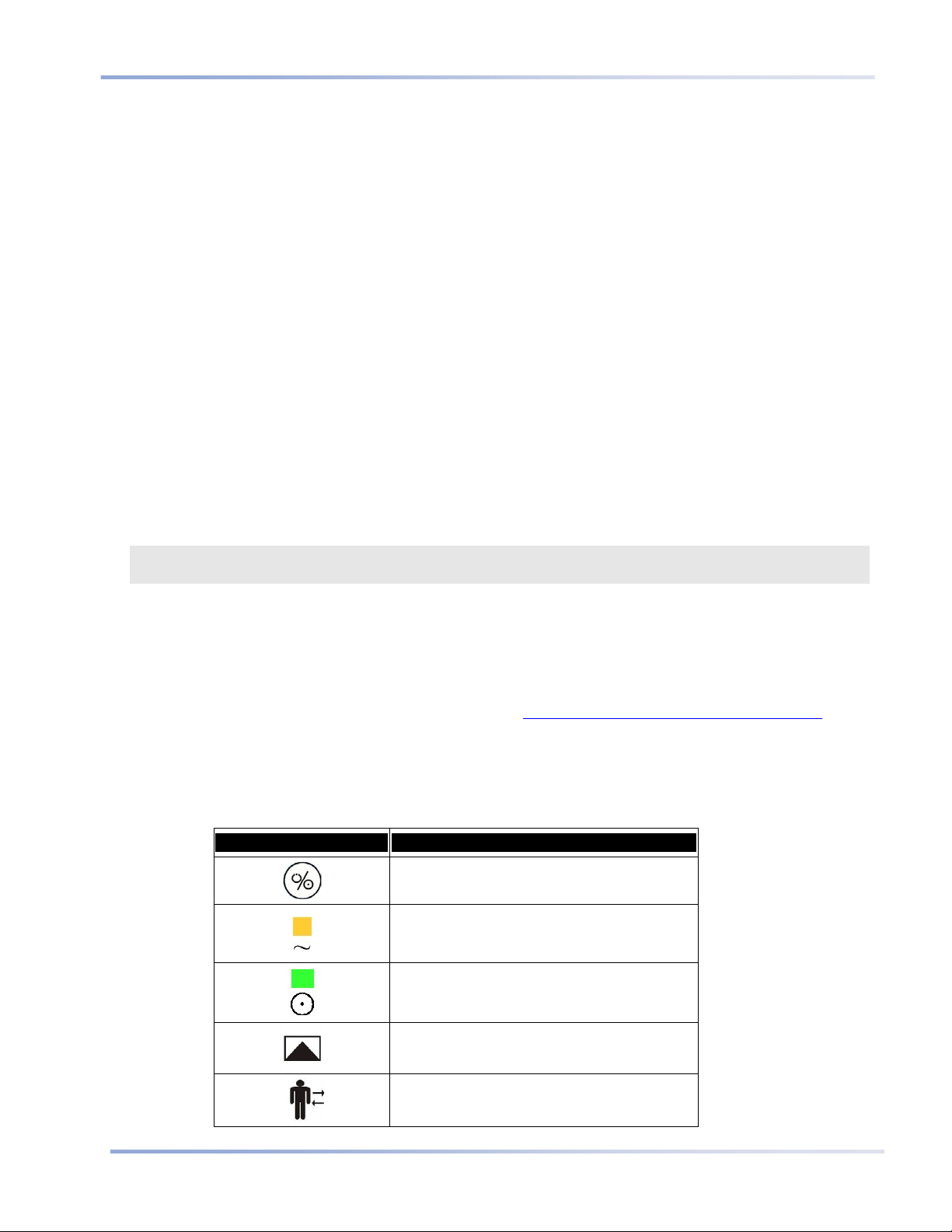
Table 1 - Symbols that Appear on the Monitor
Symbol Description
Monitor ON/OFF button
AC power ON indicator
UNIT ON indicator
.
Event selection
Patient Admit/Discharge
Symbols
Portable Bedside Capnograph/Pulse Oximeter
17
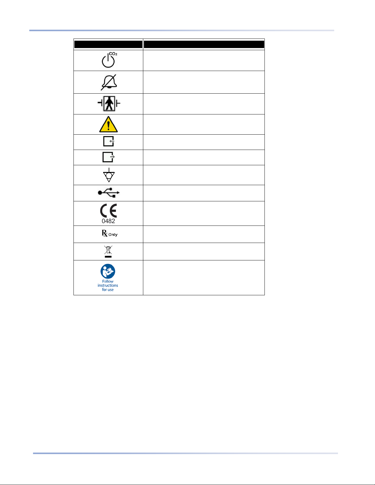
Symbol Description
Pump Off
Temporarily silence alarms
Type BF Defibrillator Proof Protection
General warning sign
Gas inlet
Gas outlet
Equipotential ground
USB flash memory connection port
CE Mark
For prescription use only
Directive on waste electrical and electronic
equipment
Follow instructi ons for use


Portable Bedside Capnograph/Pulse Oximeter
19
Chapter 2
Technology Overview
Introduction
Features
Technology Overview
Introduction
The Capnostream bedside monitor provides accurate, continuous capnography and pulse oximetry monitoring
for intubated and non-intubated patients from neonate to adult. Using Microstream
FilterLine
free" etCO
®
etCO2 consumables, and pulse oximetry technology, Capnostream allows for simultaneous "hassle
and SpO2 monitoring.
2
®
technology, patented
Features
• Dual parameter monitor that supports the current standard of care providing CO
and SpO2 measurements
2
• Integrated Pulmonary Index™ (IPI), which provides a simple, clear, and comprehensive indication of a
patient’s ventilatory status and trends
• Apneas per Hour and Oxygen Desaturation Index, indices used to help in the identification and
quantification of apnea and oxygen desaturation events (if available)
• Simple user interface with color screen
• Routine functions are accessed with 2 clicks
• 72 hour trends to review patient history
• One-click alarm review
• SARA™ (Smart Alarm for Respiratory Analysis), an embedded Smart Capnography alarm management
technology, which reduces clinically insignificant alarms
• Event marking to compare events and medication administration to changes in patient status
• Case recording to help organize patient files
• Nurse call
• Optional internal printer
• USB output to transfer patient data to USB flash memory devices
• Analog output for use in sleep labs and other laboratory environments
• RS-232 port for data transfer
Technology Overview
This section provides a basic overview of Capnography and Pulse Oximetry.
What is Capnography?
Capnography is a non-invasive method for monitoring the level of carbon dioxide in exhaled breath (etCO
assess a patient’s ventilatory status.
Capnostream uses Microstream
amount of CO
present during inhalation (FiCO2), and the Respiratory Rate.
CO
2
during every breath, the amount of CO2 present at the end of exhalation (etCO2), the amount of
2
®
2
non–dispersive infrared (NDIR) spectroscopy to continuously measure the
) to

Technology Overview
20
Portable Bedside Capnograph/Pulse Oximeter
Infrared spectroscopy is used to measure the concentration of molecules that absorb infrared light. Because the
absorption is proportional to the concentration of the absorbing molecule, the concentration can be determined
by comparing its absorption to that of a known standard.
The Microstream
consumable or directly from the patient (via an oral/nasal cannula) into the monitor for CO
Moisture and patient secretions are extracted from the sample, while maintaining the shape of the CO
®
etCO2 consumables deliver a sample of the inhaled and exhaled gases from the ventilator
measurement.
2
2
waveform.
The 50 ml/min. sampling flow rate reduces liquid and secretion accumulation, decreasing the risk of obstruction
in the sample pathway in humid ICU environments.
Once inside the Microstream
This extremely small volume is quickly flushed, allowing for fast rise time and accurate CO
®
CO2 sensor, the gas sample goes through a micro-sample cell (15 microliters).
readings, even at
2
high respiration rates.
The Micro Beam IR source illuminates the micro-sample cell and the reference cell. This proprietary IR light
source generates only the specific wavelengths characteristic of the CO
compensations are required when different concentrations of N
O, O2, anesthetic agents and water vapor are
2
absorption spectrum. Therefore, no
2
present in the inhaled and exhaled breath. The IR that passes through the micro-sample cell and the IR that
passes through the reference cell are measured by the IR detectors.
The microprocessor in the monitor calculates the CO
concentration by comparing the signals from both
2
detectors.
What is Pulse Oximetry?
Pulse oximetry is based on the following:
• The difference in the absorption of red and infrared light (spectrophotometry) by oxyhemoglobin and
deoxyhemoglobin
• Changes in the volume of arterial blood in tissue during the pulse cycle (plethysmography), and hence,
light absorption by that blood.
A pulse oximeter determines Spot Oxygen Saturation (SpO
bed and measures changes in light absorption during the pulsatile cycle. Red and infrared low power light
emitting diodes (LEDs) in the oximetry sensor serve as light sources; a photodiode serves as the photo detector.
Because oxyhemoglobin and deoxyhemoglobin differ in light absorption, the amount of red and infrared light
absorbed by blood is related to hemoglobin oxygen saturation. To identify the oxygen saturation of arterial
hemoglobin, the monitor uses the pulsatile nature of arterial flow. During systole, a new pulse of arterial blood
enters the vascular bed and blood volume and light absorption increase. During diastole, blood volume and light
absorption reach their lowest point. The monitor bases its SpO
maximum and minimum absorption (measurements at systole and diastole). The focus of light absorption by
pulsatile arterial blood eliminates the effects of nonpulsatile absorbers such as tissue, bone, and venous blood.
) by passing red and infrared light into an arteriolar
2
measurements on the difference between
2

Portable Bedside Capnograph/Pulse Oximeter
21
Do not touch this field - it is invisible and does not appear in the
Chapter 3
The Capnostream Monitor
final document
Unpacking and Inspection
Installing the Battery Pack
Mounting the Monitor
Setting up Periodic Maintenance
Accessories
Buttons, Indicators and Connections
Front Panel Control Buttons
Turning on the Monitor
Standard Sections of the Display Screen
Home Screen Numeric Display
Terminating Operation of the Monitor
Screen Navigation
Setting Date, Time, Language, and Other Options
Screen Timeouts
Capnostream
®
20p: Operational Check Sheet
This chapter describes the physical components of the monitor and how to set up the monitor so it is ready for
use.
The Capnostream
setup, and getting started processes. Photocopy the Check Sheet from the manual and check off the steps on the
Check Sheet as you set up the monitor.
®
20p Operational Check Sheet is provided at the end of this chapter to simplify the installation,
Unpacking and Inspection
Unpack the monitor and check all the components before performing any further procedures.
T
O UNPACK AND INSPECT THE MONITOR:
1. Carefully remove the Capnostream monitor and the accessories from the box.
2. Check that the items on the enclosed packing list are included:
• Capnostream Monitor
• Operating Manual
• Two 3.15 Amp Type F fuses
• FilterLine Starter Kit
• Mains Electrical Power Cord
• SpO
• SpO
Sensor Pack
2
Extension Cable
2
• Printer Paper Roll (one installed and one extra roll)
• Battery Pack
• CD with additional documentation (RS-232 Capnostream Data Transfer Protocols, the Patient Data
Transfer Application Note, and this manual in additional languages)
3. Inspect each component.
If any component is damaged or missing, contact your local representative.
Installing the Battery Pack
22
Portable Bedside Capnograph/Pulse Oximeter
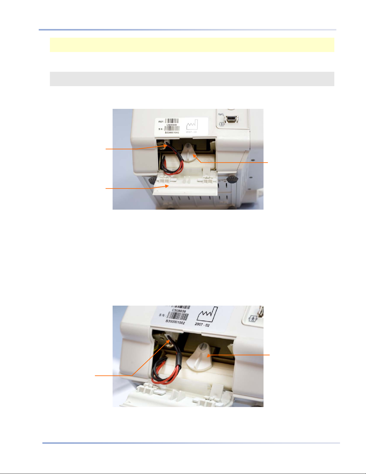
Battery
Compartment
Door
Restraining lever
Battery
Connection
Socket
Restraining lever
Battery
Connection
Socket
Note: When unpacking the monitor, packaging waste shall be disposed of as according to local regulations for
the disposal of packaging waste.
Installing the Battery Pack
WARNING: The unit should always be operated with the battery installed in order to provide back-up
power in the event of a momentary or temporary power outage.
The monitor operates on AC power or on a battery. It is equipped with a rechargeable Lithium–Ion battery pack.
To install the battery pack, open the battery cover on the side of the monitor as shown below.
Figure 1 - Installing the Battery Pack
TO INSTALL THE BATTERY PACK:
1. Slide the two release latches on the battery compartment door inward and open the battery compartment
door.
2. While holding the battery pack with the wires on the right, rotate the restraining lever up to the horizontal
position and place the battery pack in the monitor.
3. Push the battery pack all the way in.
4. Hold the battery pressed in and lock it in position by returning the restraining lever to the vertical position.
5. Attach the battery connector into the battery connection socket, ensuring that the side with the protruding
grooves is on the right, so that the connector fits into the socket. Push the wires back into the monitor.
6. Align the flaps on the battery compartment door with the slots in the monitor casing, close the door, and
Figure 2 - Battery Pack Close-up
slide the two release latches outward.
Installing the Battery Pack
Portable Bedside Capnograph/Pulse Oximeter
23
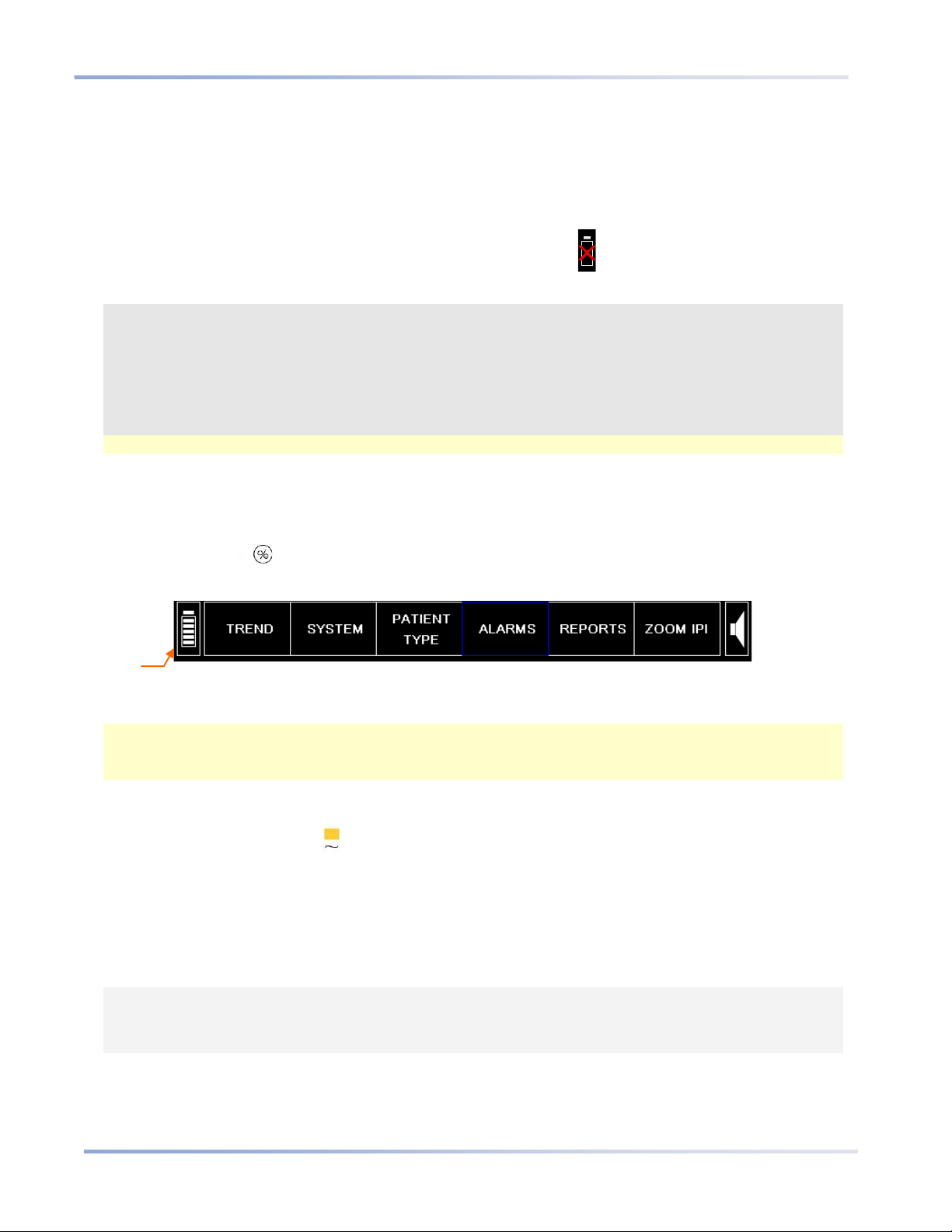
Battery Charge
Level Indicator
Ensure that the battery pack is fully charged before using the monitor without AC power. A fully charged
battery pack provides 2.5 hours of operation (without printer usage). When the monitor is connected to the AC
mains, the battery pack charges automatically. It takes approximately 12 hours to fully charge an empty battery
pack.
When you start using the monitor, verify that the battery icon at the bottom left of the monitor screen indicates
that the battery is full. Refer to Testing the Battery and AC Connections below for details.
If no battery pack is installed during monitor setup, the No Battery icon will appear on the screen and the
advisory message NO B ATTERY INST ALLED will appear.
WARNING: It is recommended to always have a battery installed. If the battery is not installed, the unit
will operate properly on AC power, but if AC power is lost for any reason the monitor will
not work.
WARNING: To replace the battery, first turn off the monitor and then unplug the unit from AC power.
Do not attempt to disconnect or connect a battery while the unit is turned on or connected to
AC power.
Note: If the battery is not fully charged, the battery icon will indicate the charge level of the battery.
Testing the Batt er y and AC Connections
The battery pack charge level and AC power connections should be confirmed before each use.
O TEST THE BATTERY:
T
1. Press the ON/OFF button to turn on the monitor.
2. Observe the battery icon level in the bottom left hand corner of the screen.
Figure 3 - Menu Bar with Battery Charge Level
3. If you have previously fully charged the battery, the battery icon should indicate that the battery is full.
Note: As part of the monitor power-up, the battery charge level indicator will show full for about 15 seconds
after the monitor is turned on. The monitor will then update the battery charge level indicator to show the
true battery level.
Recharge the battery pack when the advisory message BATTER Y L OW appears on the display screen. To
recharge the battery, make sure that the monitor is plugged into the AC mains. The orange AC power indicator
on the front panel of the monitor will light up.
For normal operation, always check that the orange AC power indicator light is on during monitor use. This will
ensure the battery is charged during use and the monitor is prepared in case of a power outage or a patient
transfer. If a patient has to be transferred to another location, the unit can be unplugged and transferred with the
patient. Care should be taken to reconnect the monitor to the AC mains following the transfer.
Handling the Battery Pack
CAUTION: Do not immerse the battery pack in water; it may malfunction.
CAUTION: Recharge the battery pack only in the monitor to avoid possible heating, burning or rupture
of the battery pack.

Installing the Battery Pack
24
Portable Bedside Capnograph/Pulse Oximeter
Storing the Battery
The battery pack must be stored in a cold, dry area, not inside the monitor. Its charge decreases over time. To
restore the battery pack to full power, recharge the battery before use. The battery should be fully recharged
every 3 months at minimum. Store at -20 to 25°C.
CAUTION: Storage or transport of the monitor under environmental conditions beyond those mentioned
in the specification will affect monitor performance and damage the battery and/or the
monitor.
Disposing of the Battery
CAUTION: Do not dispose of the battery pack in fire; it may explode.
Follow local governing ordinances and recycling instructions regarding disposal or recycling of batteries.
Battery and Power Usage
If power is lost when the monitor is operating from AC power, it automatically switches to the internal battery
pack for power. The duration of this backup power usage, based onbattery capacity, is up to 2.5 hours. The
monitor maintains its settings, including alarm settings, while on battery operation. If settings have been set in
Institutional Defaults, these settings will remain in the monitor memory even if the monitor is not receiving
power at all, and will be available once the monitor is turned on again. Likewise, trend data in the device will
remain in the monitor memory even if the monitor is not receiving power at all, and will be available once the
monitor is turned on again.
The orange AC power indicator light is on when the monitor operates from an external power source, with no
relation to the status of the battery pack.
The green power-on indicator is on when the monitor is switched on.
If the orange AC power indicator light is off and the green power-on indicator is on, the monitor is operating
from the battery pack.
The battery icon will show the battery pack’s approximate charge level. An advisory message, BATTERY
LOW, appears when approximately 15 minutes of battery charge (equivalent to 14.0 V) remains.
Mounting the Monitor
Portable Bedside Capnograph/Pulse Oximeter
25
to Mounting the Monitor on page 25 for
Mounting the Monitor
The bottom of the Capnostream device is designed to fit a 100mm VESA standard mounting plate. (An example
is the GCX model FLP-002-17C mounting plate which fits onto the GCX model RS-0006-64D Roll Stand
Assembly). The VESA mounting plate can be ordered from Oridion; part number is 010713. Please refer to the
appropriate Directions for Use for these products.
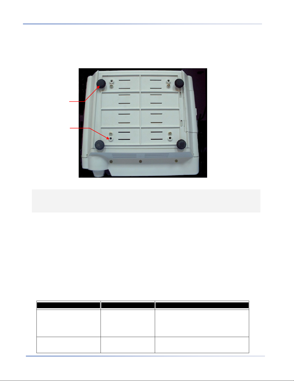
Rubber
feet (4)
Mounting
Holes (4)
Figure 4 - Monitor Bottom View
CAUTION: Do not remove the rubber feet from the bottom of the monitor. These rubber feet are
required for operation of the monitor on a table, to prevent unwanted movement of the
monitor while in use. Even if the rubber feet are not currently in use, it is suggested that you
keep them in place for future need.
Setting up Periodic Maintenance
If your institution has a periodic maintenance database, log the monitor in this database for its periodic
calibration procedure. Calibration is required after the first 1,200 hours of use (or 12 months, whichever comes
first) and thereafter every 4,000 hours of use (or 12 months, whichever comes first). The number of operating
hours will appear just after the monitor turns on and on the monitor’s Service Screen. For more details about
calibration and other maintenance procedures, see Maintenance and Troubleshooting on page 111.
Accessories
Available Accessories
See the list of available accessories for Capnostream below.
Table 2 - Capnostream Accessories
Accessory Oridion Part Number Use
Paper (6 rolls) 010516 Paper fits Capnostream's inte g r ated printer.
Monitor is shipped with one paper roll and one
spare paper roll. Refer to Replacing the
Printer Paper Roll on page 115 for paper
installation.
Mounting Adaptor Plate
(Vesa)
010713 Used for mounting Capnostream to GCX roll
stands and other mounting assemblies. Refer

Buttons, Indicators and Connections
26
Portable Bedside Capnograph/Pulse Oximeter
mounting instructions.
Accessory Oridion Part Number Use
Quick Release Pole Clamp 011782
Roll Stand with Basket Not stocked by Oridion GCX model RS-0006-64D
Mounting Adapter for Bernoulli
Transmitter
Battery Pack 016400 Refer to Installing the Batter y Pack on page
Nurse Call Cable 011149 Cable length 3.5 meters: Cable is supplied un-
US Power Cord 014256
European Power Cord 014255
011892
Clamp fits pole mount (pole diameter 0.75in
[19mm] to 1.5in [38mm]) or rail mount (rail
size 10mm [0.39in] x 25mm [0.98in]).
With quick release mechanism.
Mounting adapter plate is included.
Roll Stand Kit 38" post with 5" Slide-in type
mounting plate – including: 21" base, 4"
casters, 10lb Counterweight, handle, and 6"
basket.
Mounting plate is required to use Roll Stand.
Used with a Bernoulli/Oxinet hospital system.
Refer to Operation with Hospital Patient Data
Systems on page 110.
22 for battery installation.
terminated so it can be built to fit system.
Refer to Nurse Call Operation on page 107 for
set up instructions.
Monitor Mounting Pl ate
The mounting kit contains a VESA Mounting Adapter, 100 x 100mm to 75 x 75mm, which can be affixed to the
bottom of the monitor as described above. This allows the monitor to be mounted on a wide range of GCX
stands and mounts including the GCX model RS-0006-64D Roll Stand Assembly. Please contact GCX
(www.gcx.com) for more information on their available solutions for mounting the monitor.
Please note that when mounting the monitor on a roll stand or other pole mount, it is important to use a stand
that has a minimum 21 inch (53.5 cm) wheel base diameter, to ensure stability.
Printer Paper
The monitor uses thermal printer paper with the following specifications:
Paper Width 58mm (2 ¼ in)
Paper Roll Diameter (maximum) 40mm (1 1/2 in)
Paper Length (maximum) 15.2 meters (50 ft)
Note: Some manufacturers use a different thickness of paper, so that a 15.2 meter roll from a different
manufacturer may exceed the maximum diameter limit and will not fit in the monitor.
Replacement paper rolls that meet the specifications can be obtained from Oridion (part number 010516 for a
package of 6 rolls), or in North America from www.thermalpaperdirect.com (Model number 22550).
Buttons, Indicators and Connections
Following are the front, rear, and side views of the monitor showing the display, controls, and external
connection points.
Table 3 - Printer Paper Specifications
Item Value
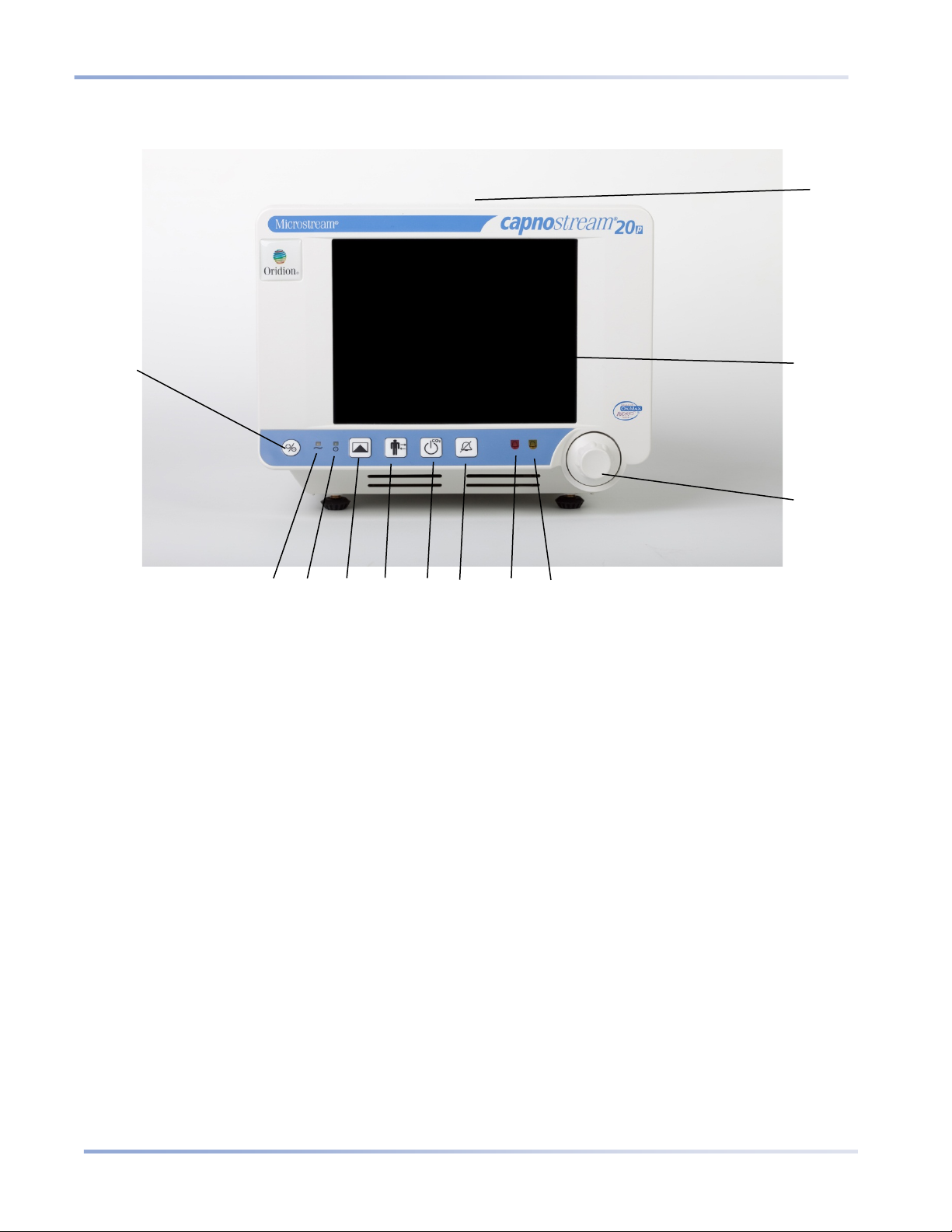
Buttons, Indicators and Connections
Portable Bedside Capnograph/Pulse Oximeter
27
10
11
12 8 5
9
3
2
4
6
1
Monitor Front View
The front panel of the monitor contains the display screen, action buttons and the control knob.
Figure 5 - Capnostream Front Vie w
Table 4 - Capnostream Front View lists the numbered labels.
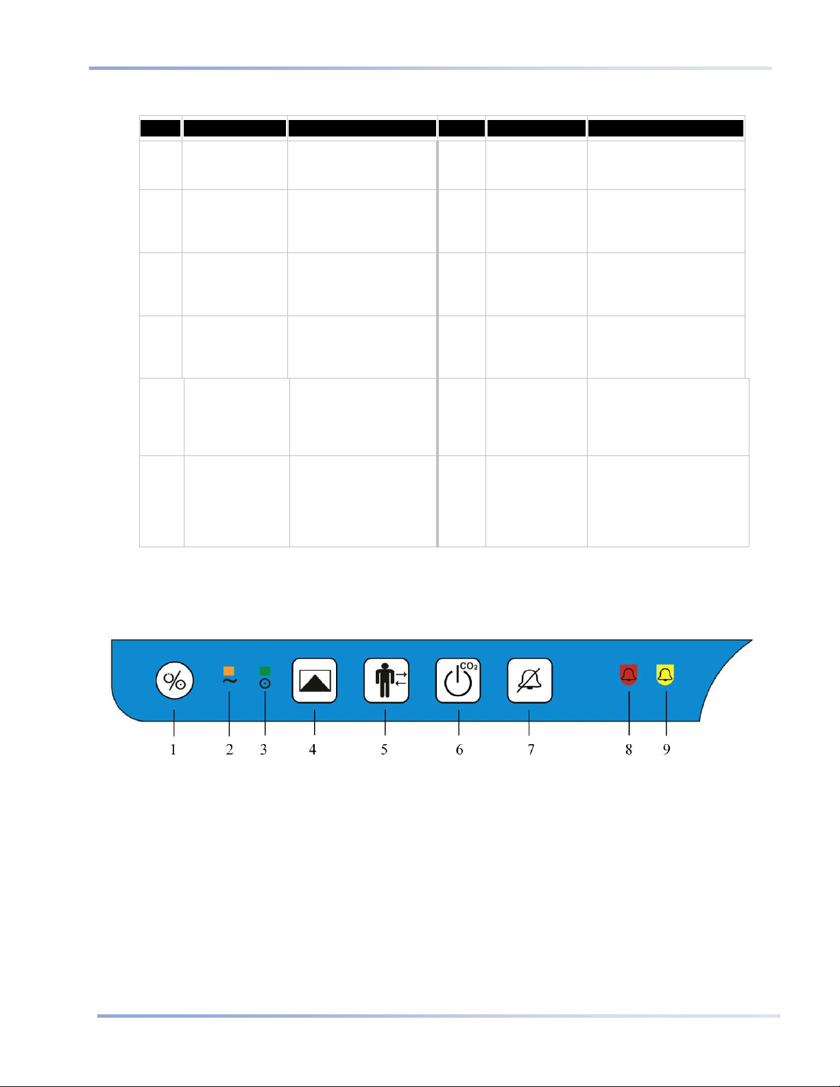
Front Panel Control Buttons
28
Portable Bedside Capnograph/Pulse Oximeter
Table 4 - Capnostream Front View
Label
1 Monitor power
2 AC power
3 Monitor power
4 Event button Starts the process of
5 Patient
6 Pump Off button Shuts off the
Name Description Label Name Description
Button switch 7 Temporary
ON/OFF
Orange light 8 Red alarm
indicator
Green light 9 Yellow alarm
on indicator
placing either a Quick or
Detailed Event marker in
the trend data.
Allows Starting and
Admit/Discharge
button
Stopping a case and
entering patient ID.
Capnography pump for
a preset time in order to
protect the monitor
during suctioning
procedures.
Temporarily disables the
alarm silence
button
indicator
indicator
10 Control knob Rotary knob used to
11 Display screen Screen displaying the
12 Carrying
handle
Audio Alarm for two
minutes.
Indicator that flashes
during High Priority
alarms (see High Priority
Alarms on page 73).
Indicator that lights or
flashes according to the
alarm status (see Alarm
Display on page 70).
navigate the screen and
select a function when
pressed.
patient data, menu bar,
patient mode, date-time,
and any information or
error messages.
Allows the monitor to be
carried.
Front Panel Control Buttons
The figure below is a close-up of the controls shown in Figure 5 - Capnostream Front View on page 27 and
described in Table 4 - Capnostream Front View above.
Figure 6 - Front Panel Control Buttons
 Loading...