


11.06/WE
OR-T 300
DEUTSCH 3
ENGLISH 14
FRANÇAIS 25
ITALIANO 36
Akku-Handgerät zum Umreifen mit Kunststoffband
Battery-hand tool for plastic strapping
Appareil sur accu pour le cerclage par bande plastique
Apparecchio da batteria per reggiare con reggetta di plastica
Ab Serie-Nr. 3/63500
From serie no 3/63500
A partir du no de série 3/63500
A partire dal no di serie 3/63500
BETRIEBSANLEITUNG UND SICHERHEITSVORSCHRIFTEN
OPERATING AND SAFETY INSTRUCTIONS
MODE D‘EMPLOI ET DE SÉCURITÉ
ISTRUZIONI PER L‘USO E DI SICUREZZA
Vor dem Gebrauch des
Gerätes die Betriebsanleitung aufmerksam
lesen.
Before using the tool,
read the operating
instructions carefully.
Avant l’utilisation de
l’appareil, consultez
soigneusement le
mode d’emploi.
Prima d’utilizzare
l’apparecchio, leggere
attentamante le istruzioni per l’uso.

14
11.06/WE
ORGAPACK OR-T 300
1 TECHNICAL DATA
TABLE OF CONTENTS
Page
1 Technical data 14
2 General information 15
2.1 Information on environmental protection 15
3 Safety instructions 16
3.1 Safety instructions for battery
charger and battery 16
4 Description 17
4.1 Construction 17
4.2 Operating panel 17
4.3 Function 17
4.4 Battery charger 18
5 Initial operation 19
5.1 Battery charger 19
5 .2 First battery charge 19
5.3 Charging the battery 19
6 Operating instructions 20
6.1 Operating the tool 20
6.2 Checking the seal 21
6.3 Operating panel 22
6.3.1 Checking battery charge 22
6.3.2 Setting strap tension 22
6.3.3 Setting welding time 22
6.3.4 Setting strap tension range 23
6.4 Setting strap width 23
7 Preventive and corrective maintenance 24
7.1 Cleaning/replacing tension wheel 24
7.2 Cleaning/replacing tooth plate 24
7.3 Replacing cutting knife 24
8 Recommended spare parts 47
8.1 Parts list 47
Exploded drawing 53
Weight 4.2 kg (9.9 lbs) (incl. battery)
Dimensions Length 375 mm (14.7“)
Width 130 mm (5.1“)
Height 140 mm (5.5“)
Strap tension 400–3300 N (88–727 lbs)
Tension speed 250 mm/s (9.8“/s)
Sealing Friction welded
Emission sound pressure
levels, measurement
type A (EN ISO 11202) LpA 85 dB (A)
Vibrations at handle
(EN ISO 8662-1) a
h,w
2.2 ms
-2
BATTERY Bosch 14.4 V HD
Strappings with
one battery charge 120–250 (PP)
80–150 (PET)
depending on strap, strap
tension and package
Service life Up to approx 2000
chargings
BATTERY CHARGER IFC 1702dx
Voltage 100–240 V
Mode of operation Discharge/Charge
Charging time approx. 60–75 minutes
(incl. previous discharging)
PLASTIC STRAP
Strap quality Polypropylene (PP)
Polyester (PET)
Strap width
adjustable to 15–16 mm (5/8“) (PET),
18–19 mm (
3
/4“) (PET, PP)
Strap thickness Polypropylene
0.8–1.0 mm (.031“–.039“)
Polyester
0.8–1.3 mm (.031“–.051“)
DECLARATION OF AGREEMENT
According to norm:
EN ISO 12100-1, EN ISO 12100-2, EN 349,
EN 1050, EN 61000-6-1, EN 61000-6-3
CH-8953 Dietikon, 11.10.2005
Sales Manager General Manager Products
Packaging Technology: Packaging Technology:
R. Kieffer M. Binder
We take sole responsibility for declaring that the
tool OR-T 300, to which this declaration refers, is
in full compliance with the current requirements of
the guidelines laid down by the council on 22th
June 1998 (98/37/ECC), “Machine Guidelines“.
Furthermore, electrical installations are in compli ance with the guideline laid down by the council on
19. February 1973 (73/23/EEC) “Low Voltage Gui
delines“ and from 3th May 1989 (89/336/EEC)
“EMV Guidelines“.

15
11.06/WE
ORGAPACK OR-T 300
CAUTION!
Used where there is danger to life and health.
WARNING!
Used for danger which
can cause material
damage.
NOTE!
Used for general information and information
which, if not followed
can cause faults in the
operating sequence.
2 GENERAL INFORMATION
These operating instructions are intended to simplify
familiarisation with the strapping tool and its proper
use for the intended purpose. The operating instructions contain important information concerning the
safe, proper and effi cient use of the strapping tool.
Compliance with the instructions will help to avoid
danger, reduce repairs and stoppages and increase
the reliability and service life of the strapping tool.
The operating instructions must always be available at
the place of operation of the strapping tool. They must
be read and observed by all persons concerned with
work on the strapping tool. This work specifi cally
includes operation, refi lling of operating material, fault
elimination and maintenance.
In addition to the operating instructions and the regulations for accident prevention effective in the country
of use and place of application, the recognised technical regulations for safety and proper operation must
also be observed.
2.1 INFORMATION ON ENVIRONMENTAL
PROTECTION
This tool is manufactured without any physical or chemical substances which could be dangerous to health.
For disposal of all the parts, the governmental instructions must be observed. The electrical assemblies
should be dismantled so that the mechanical, electromechanical and electronic components can be disposed of separately.
Dealers provide an
environmentally-
friendly battery
disposal service
• Do not open the
battery.
• Do not throw the
used battery into hou sehold waste, fi re or
water.
Defective or used
batteries undergo a
complete recycling
process.
16
11.06/WE
ORGAPACK OR-T 300
Original ORGAPACK spare
parts must be used exclusively!
Not using original spare parts
will dissolve the warranty and
the liability.
Use for the intended purpose
This tool is designed for strapping packages, pallet
loads and the like.
The tool was designed and manufactured to provide
safe handling during the strapping operation.
The tool is designed for use with plastic straps (polypropylene and polyester).
Possible misuse
The use of steel straps is not possible.
3.1 SAFETY INSTRUCTIONS FOR BATTERY
CHARGER AND BATTERY
Always inspect the electrical
plug and cable before use. If
damaged, they must be
replaced by qualifi ed personnel.
• Do not charge other types of batteries (see chapter
5.1) and use original accessories only.
• Keep the battery charger slot free of foreign objects
and protect against dirt.
• Protect the battery charger against humidity and
use it in dry areas only.
• Do not open the battery. Protect the battery against
impact, heat and fi re. Risk of explosion!
• When the battery is outside the battery charger,
cover its battery terminals to avoid short circuits
with metal objects. Risk of fi re and explosion!
• Keep battery dry and protected against frost. Do
not store it at temperatures over 50°C or below
10°C.
• Damaged batteries should not be used longer.
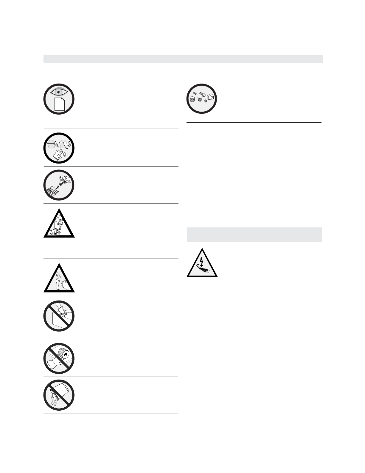
3 SAFETY INSTRUCTIONS
Inform yourself!
Read the operating instructions
carefully.
Preventive and corrective maintenance on the tool may only
be carried out by trained personnel.
Protect yourself!
When operating the tool, wear
eye, face and hand protection
(cut-proof gloves).
Power source!
Before starting preventive or
corrective maintenance, remove battery from the tool.
Warning:
Strap will snap forward!
When cutting the strap, hold
the upper portion and stand
safely away from the strap.
Caution:
The lower strap will snap
forward.
Warning:
Strap could break!
Do not stand in line with the
strap while it is tensioned. The
strap could break!
Caution:
Only strap packed goods!
Do not put hands or other parts
of the body between the strap
and the package during the
strapping process.
Caution:
Danger of squeezing!
Do not put your fi ngers into the
tension wheel area.
Do not use water!
Do not use water or steam to
clean the tool.
ORGAPACK
Original
jklsfjklsdjš
lksdfjkl
jkljsdllkjjkljsd
fkljjklkjkljsdafj
asdfjklkjjkljklj
ksldafkjkljklš
jkljklkljsdafjlkj
jkljjkljklkljljlk
17
11.06/WE
ORGAPACK OR-T 300
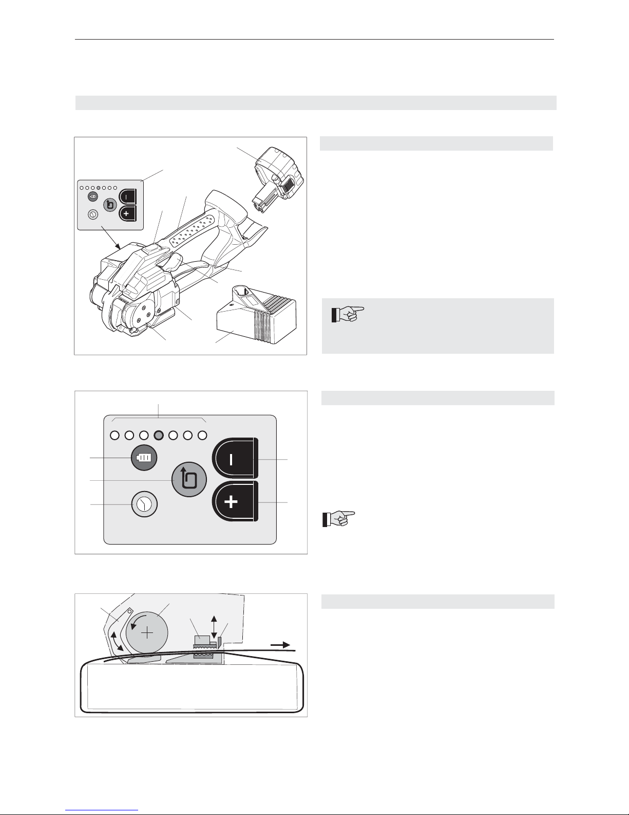
4 DESCRIPTION
4.3 FUNCTION
– Clamping of the straps by tooth plate on rocker
(3/1).
– Tensioning by feed wheel (3/2) anti-clockwise.
– Friction welding (3/3) of the straps.
– Upper strap is cut by knife (3/4).
4.1 CONSTRUCTION
1 Operating panel
2 Strap tensioning push button
3 Handle
4 Battery
5 Rocker lever
6 Welding/cutting button
7 Welding/Cutting
8 Tensioning
9 Battery charger (refer to chapter 4.4)
4.2 OPERATING PANEL
1 Welding time push button
2 Strap tension push button
3 Battery push button
4 LED-indicators 1–7
Green = Strap tension setting
Red = Battery empty indicator
5 Setting – push button
6 Setting + push button
For detailed information of the operating
panel, refer to chapter 6.3.
1
2
3
4
Fig. 3
Fig. 2
7
6
5
4
3
2
1
1
2
3
4
5
6
Note on performance
In order to achieve peak performance, only
original batteries and charger may be used.
7654321
Fig. 1
1
2
3
4
5
6
7
8
9
18
11.06/WE
ORGAPACK OR-T 300
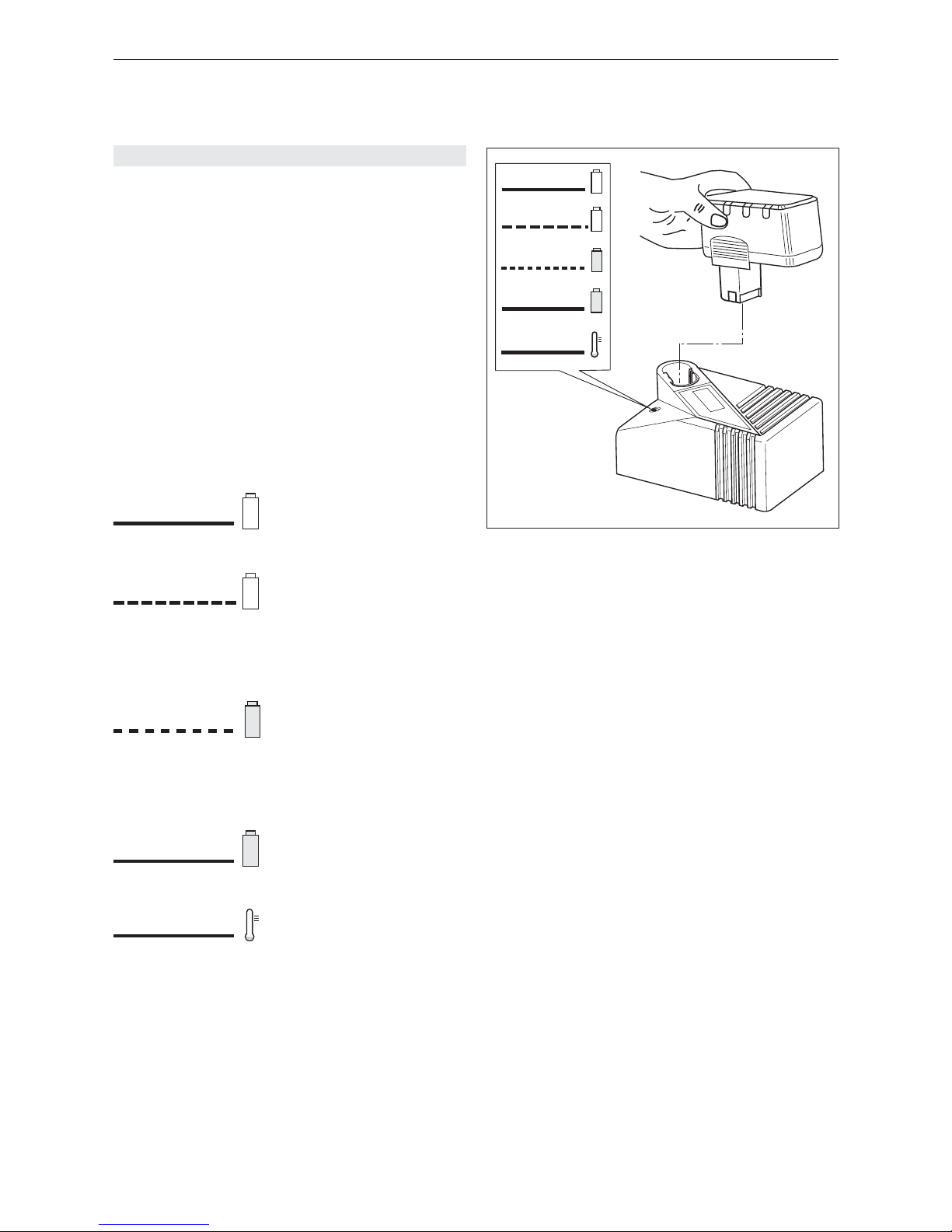
4.4 BATTERY CHARGER
The battery charger (IFC1702dx) is a special device
with both charging and discharging functions for maximum battery power and life.
– When a battery is placed in the charger, the remai ning charge level is tested fi rst. If the battery is not
completely discharged, the charger will fi rst empty it.
– After discharging, the battery charger switches auto matically to charge. The battery will be fully charged
in four steps by the pulse charging technique.
Battery discharging time: approximately 15 minutes
with discharged battery from
strapping machine
Battery charging time: 14.4 V/2.4 Ah
> +/- 60 minutes
No indicator
illuminated
Continuous
orange light
Flashing
orange light
Flashing
green light
Continuous
green light
Battery charger indicators:
Ready for charging
Mains supply is connected.
Battery not inserted or inter rupted (defective).
Discharging
Discharging runs until the
minimal Cell-voltage has
been achieved. The appli ance then automatically
switches to th charching
state.
Rapid charging
Rapid charging operates
until the battery is fully re charged. The battery char ger then switches automati cally to toppic- and trickle
charging.
Trickle charging
Battery is fully charged.
The battery charger is deli vering only a trickle charge.
Temperature
Warning: the battery is too
hot (or too cold). Trickle
charging only.
The battery charger swit ches automatically to rapid
charging when the tempera ture is within the permitted
range again.
Mains supply not connected:
electrical plug, cable or
battery charger defective.
Continuous
orange light
Fig. 4
19
11.06/WE
ORGAPACK OR-T 300
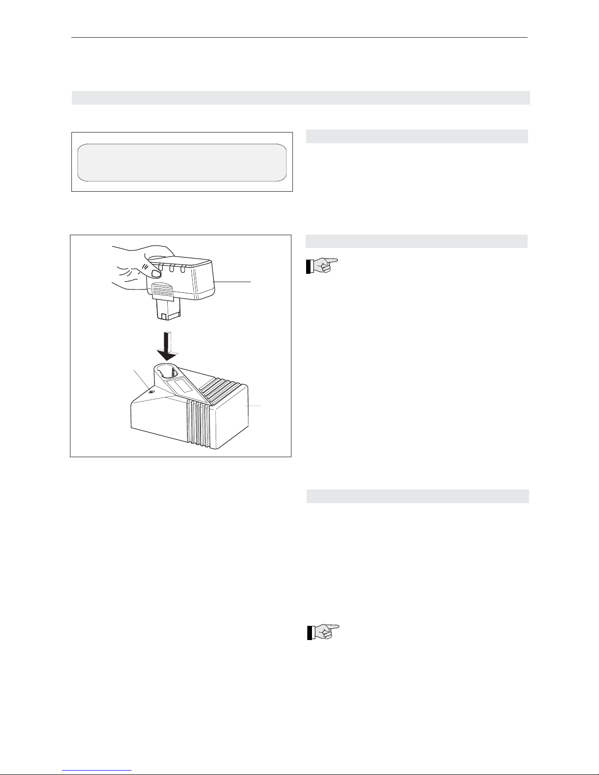
5 INITIAL OPERATION
5.1 BATTERY CHARGER
The mains supply must comply with the specifi cations
on the rating plate (Fig. 5).
The battery charger is suitable only for charging
batteries from the Bosch range of tools (NiCd/
NiMH) with the voltage of 14.4 V.
5.2 FIRST BATTERY CHARGE
Please observe the following points in order
to ensure optimum battery life:
– Connect battery charger (6/2) to mains supply.
– Insert battery (6/1) into battery charger slot.
For the fi rst charge, leave the battery in the charger for at least fi ve hours, regardless of the battery indicator (the charging time for all subsequent
charges is about 60 minutes).
For all subsequent charges, only recharge the
battery when the LED indicator on the tool indicates battery empty or the battery charge indicators
shows a minimum of level 5 or lower (see Chapter
6.3.1).
Maximum battery output will be reached after four or
fi ve charging/discharging cycles.
5.3 CHARGING THE BATTERY
The charging process and error functions are indicated by a LED (6/3) (see chapter 4.4).
The charging time is approximately 60–75
minutes.
The maximum charging current fl ows when the temperature of the battery is between 15–40°C. Avoid
charging the battery at temperatures below 0°C and
above 40°C.
If the battery is not to be used for a longer
period (several days), it should be removed from the tool and charged/stored in the battery charger.
Fig. 5
Input 90-135VAC, 170-264VAC / 47...65 Hz
Battery Type: Bosch NTC-Battery 14,4V
Fig. 6
1
2
3

20
11.06/WE
ORGAPACK OR-T 300
6 OPERATING INSTRUCTIONS
Fig. 7 Place strap around package
1
Fig. 9 Strap tensioning
1
Fig. 8 Slide straps into tool
1
6.1 OPERATING THE TOOL
– Insert charged battery (7/1) into strapping tool.
– Place strap round goods to be packaged, so that
the straps lie one above the other on top of
package. The beginning of the strap is underneath.
Hold the straps with the left hand so that the strap
beginning is approximately 20 cm (8“) ahead of the
hand.
– Take the tool in the right hand and lift the rocker
lever (8/1) towards the handle.
– Slide the straps, one on top of the other, into the
tool up to the stop.
The strap lead is now approximately 5 cm
(2“) beyond the tool.
– Release the rocker lever.
– Press the push button (9/1). The strap is tensioned
until the required or pre-selected strap tension is
reached.
– The strap tension can be adjusted on the oper ating panel (see Chapter 6.3.2).
– The strap can be re-tensioned at any time.
Releasing strap tension
In order to release the strap tension after the tensioning process, lift rocker lever (8/1) against handle.
Tensioning – welding:
The welding may also be started before the
strap has been tensioned. However, the tensioning
button must be pressed once before welding.

21
11.06/WE
ORGAPACK OR-T 300
– Depress button (10/1) completely to the stop. The
straps are welded together and the upper strap is
cut off. The LED indicator (10/2) indicates the cooling
time of the sealing:
LED fl ashing
After fi nishing the friction wel ding, the green LED fl ashes for
approx. two seconds.
Do not remove the tool during
this time!
Continuous LED and audible
signal
The sealing cycle is fi nished.
If the straps have not been welded and an
audible signal sounds, this means the tension
button was not depressed.
– After the LED has stopped fl ashing and the audible
signal sounds, raise the rocker lever up to the
handle.
– Swing the tool away from the strapping backwards
and to the right.
– Check the seal (refer to chapter 6.2).
If the tool is used in a dirty environment, it is
recommended that it should be cleaned daily.
In particular the tension wheel and the tooth plate
should be checked for damage and kept clean. This is
best performed by blasting with compressed air (wear
goggles).
Fig. 10 Welding straps
1
2
Fig. 11 Removing tool
6.2 CHECKING THE SEAL
– Check appearance of seal (see fi g. 12) regularly.
If the straps are poorly welded, check the welding
time setting (refer to chapter 6.3.3).
1 Good seal (the complete surface is cleanly welded
without excess material being forced out sideways).
2 Poorly welded seal (not welded over the complete
surface), welding time too short.
3 Poorly welded seal (excess material is forced out
sideways), welding time too long.
An incorrectly welded strapping cannot
secure the package and can thus lead to
injuries.
Never transport or move packaged
goods with incorrectly welded seals.
+
~2 sec.
Fig. 12 Checking of seal
1
2
3

22
11.06/WE
ORGAPACK OR-T 300
6.3 OPERATING PANEL
a) Standard indication (green)
The current strap tension setting is monitored with
inserted and charged battery.
1 = minimum strap tension (approx. 400 N)
7 = maximum strap tension (approx. 1400/3300 N*)
* depending on strap tension range, refer to chap ter 6.3.4.
– For adjustment of strap tension, refer to chapter
6.3.2.
b) Battery empty indication (red)
If the inserted battery is empty, the LED switches to
red and the battery must be charged, refer to chapter
5.3.
Fig. 13
7
6
5
4
3
2
1
a) Standard indication
green
red
b) Battery empty indication
max. min.
7654321
7
6
5
4
3
2
1
6.3.1 CHECKING BATTERY CHARGE
– Depress battery push button (14/1) briefl y. Read off
battery charge on LED indicator (14/2).
1 = empty battery
1–3 = minimum charge (battery must be charged
soon)
1–5 = decreasing charge (charging possible)
1–6 = good charge (charging would damage the
battery)
1–7 = maximum battery charge (charging would
damage the battery)
6.3.2 SETTING STRAP TENSION
– Depress strap tension push button (15/1) briefl y
until LED indicator (15/3) fl ashes.
– Depress – or + push button (15/2) until fl ashing
LED indicator shows required strap tension (wait
two seconds until new setting is saved).
1 = minimum strap tension (ca. 400 N)
7 = maximum strap tension (ca. 1400/3300 N*)
* refer to Chapter 6.3.4.
6.3.3 SETTING WELDING TIME
– Depress welding time push button (16/1) briefl y
until LED indicator (16/3) fl ashes.
– Depress – or + push button (16/2) until fl ashing
LED indicator shows required welding time (wait
two seconds until new setting is saved).
1 = minimum welding time
7 = maximum welding time
Cutting:
The cutting of the strap is infl uenced by the
welding time. If the tool cuts badly, extend the welding
time by one interval.
Fig. 14
7
6
5
4
3
2
1
max. min.
red
12
Fig. 15
1
2
7
6
5
4
3
2
1
green
max. min.
3
Fig. 16
1
2
red
max. min.
3
7
6
5
4
3
2
1
23
11.06/WE
ORGAPACK OR-T 300
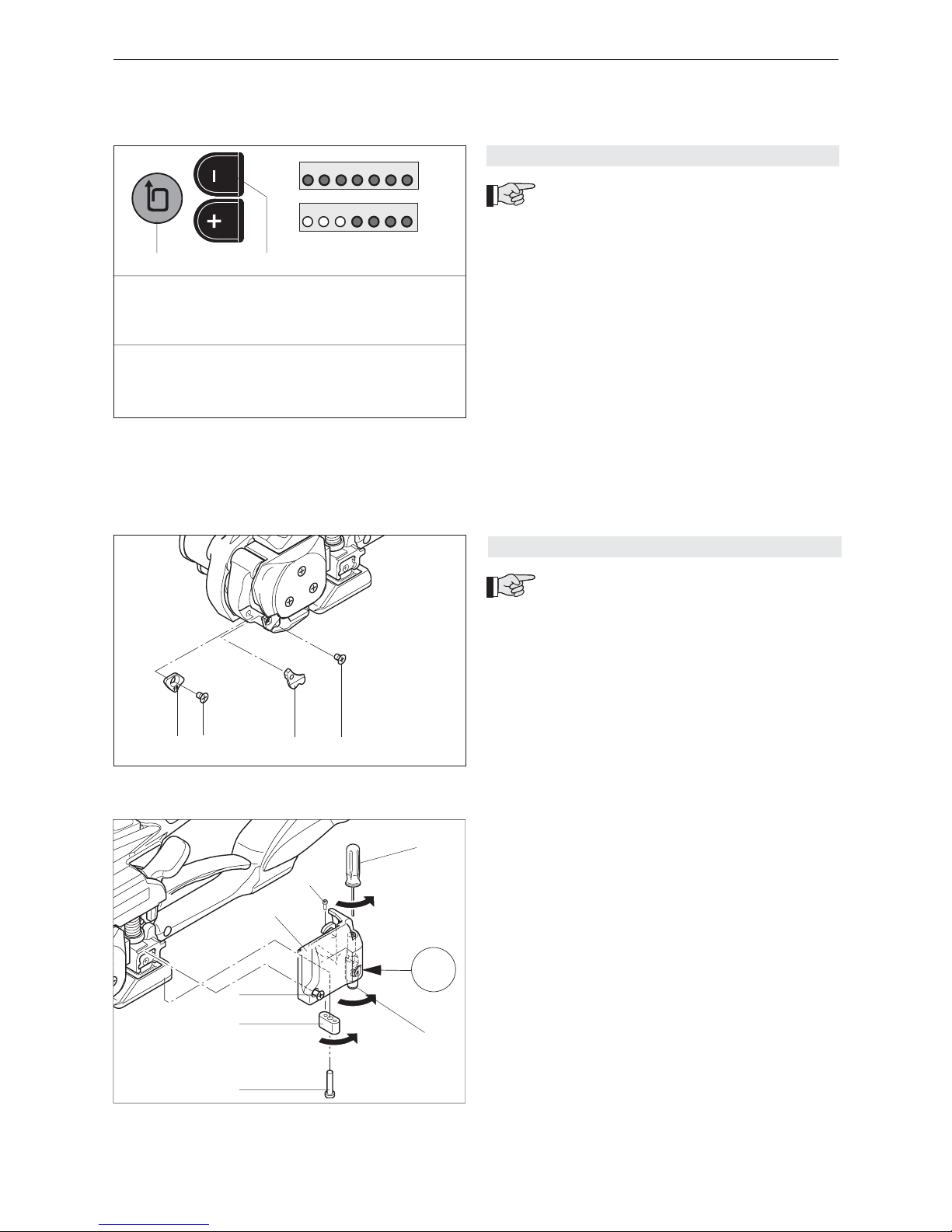
6.4 SETTING STRAP WIDTH
The tool can be used with two different strap
widths (15–16 mm (
5
/8“) or 18–19 mm (3/4“).
a) Change strap width from 15–16 mm to 18–19 mm
– Remove battery from tool.
– Release sunk screw (18/2) and remove strap stop
16 mm (18/1).
– Lift the rocker lever towards the handle, release
sunk screw (18/4) and remove strap guide 16 mm
(18/3).
– Release sunk screw (19/3) and cylinder screw (19/1)
and remove cover (19/4).
– Release cylinder screw (19/5) turn strap stop (19/2)
180° and remount it.
– Unscrew threaded bolt eight turns with screwdriver
(19/6).
– Pull down strap guide (19/7) and turn it 180° until
19 mm indicator appears.
– Tighten threaded bolt with screwdriver (19/6) and
mount cover (19/4).
– Secure screws (19/1) and (19/3) with Loctite 222.
b) Change strap width from 18–19 mm to 15–16 mm
– Sequence as described under point a).
– Mount 16 mm strap stop (18/1) and secure sunk
screw (18/2) with Loctite 222.
– Mount 16 mm strap guide (18/3) and secure sunk
screw (18/4) with Loctite 222.
– Turn strap stop (19/2).
– Turn strap guide (19/7) until “16“ indicator appears.
6.3.4 SETTING STRAP TENSION RANGE
The following two strap tension ranges can
be set on the tool:
A = 400–3300 N (standard, PET straps)
B = 400–1400 N (recommended for Polypro-
pylene (PP) straps)
Check strap tension range
– Depress and hold down “–“ push button (17/2), and
depress strap tension push button (17/1) for one
second.
– If the LEDs 1–7 are fl ashing = A (400–3300 N)
– If the LEDs 1–4 are fl ashing = B (400–1400 N)
Change strap tension range
– Depress and hold down “–“ push button (17/2), and
depress strap tension push button (17/1) for one
second.
– Depress “–“ or “+“ push button briefl y so strap
tension range changes (wait two seconds until new
setting is saved).
Fig. 17
7654321
7654321
= A
= B
1
2
Fig. 18
12
34
Fig. 19
180°
180°
8 x
16/19
1
2
3
4
5
7
6
* Standard values! Actual value on package depends
on strap and package.
A)
1 2 3 4 5 6 7
400* 750* 900* 1300* 1600* 2000* 3300 N*
B)
1 2 3 4 5 6 7
400* 600* 750* 900* 1100* 1300* 1400 N*

24
11.06/WE
ORGAPACK OR-T 300
7 PREVENTIVE AND CORRECTIVE MAINTENANCE
7.1 CLEANING/REPLACING TENSION WHEEL
Removal
– Remove battery from tool.
– Release three sunk screws (20/2) and remove cover
(20/3) with ball bearing.
– Lift rocker lever (20/4) and remove tension wheel
(20/1).
– Clean the tension wheel with compressed air (wear
goggles).
– If the tension wheel teeth are covered with heavy
dirt, they must be carefully cleaned with the wire
brush supplied.
– Check tension wheel for worn teeth. If a few teeth
are broken, replace tension wheel (observe rotating
direction, see arrow)
The tension wheel must not be cleaned
while it is rotating. There is a risk of
breaking teeth!
Installation
– Install the parts in reverse order.
– Grease gear teeth of tension wheel lightly with
Klüber grease GBU Y 131 (Microlube).
– When mounting tension wheel lift rocker lever.
– Secure sunk screw (20/2) with Loctite 222.
7.2 CLEANING/REPLACING TOOTH PLATE
Removal
– Remove battery from tool.
– Release sunk screw (21/1) and remove tooth plate
(21/2).
– Clean tooth plate with compressed air (wear
goggles).
– If the tooth plate teeth are covered with heavy dirt,
they must be carefully cleaned with the wire brush
supplied or a sharp tool.
– Check tooth plate for worn teeth, if necessary
replace tooth plate.
Installation
– Install the parts in reverse order.
– Secure sunk screw (21/1) with Loctite 222.
7.3 REPLACING CUTTING KNIFE
Removal
– Remove battery from tool.
– Release sunk screw (22/2) and cylinder screw
(22/1) and remove cover (22/3).
– Release cylinder screw (22/6) and remove cutting
knife (22/4) with fl anged bushing (22/5). Replace
cutting knife.
Installation
– Install the parts in reverse order.
– Before install cutting knife, check that the compres sing spring on top of knife is still mounted.
– Secure screw (22/1), (22/2) and (22/6) with Loctite
222.
All preventive maintenance tasks can be
performed with a Phillips screw driver!
Fig. 22
1
2
3
4
5
6
Fig. 21
1
2
Fig. 20 (3 = Tension wheel type for OR-T 300)
2
1
3
3
4

47
11.06/WE
ORGAPACK OR-T 300
Pos. Artikel-Nr. Benennung Part name Article Articolo Stück
Part no Quantity
No d‘article Pièce
Art. nr. Pezzi
38 1821.047.008 Spannrad Tension wheel Molette de tension Rueda tensora 1
46 1821.048.011 Zahnplatte Tooth plate Plaque dentée Piastra dentata 1
95 1821.209.022 Messer Cutter knife Couteau de coupe Coltello 1
1 1832.011.135 Grundplatte komplett, inkl. Pos. 3-5 Base plate complete, incl. pos. 3-5 Plaque de base, complète, incl. pos. 3-5 Piastra di base completa, incl. pos. 3-5 1
2
3 1935.510.150 Radial-Gleitlager, Ø10/12 x 15 Slide bearing Palier lisse Cuscinetto liscio, assiale 2
4 1935.512.080 Radial-Gleitlager, Ø12/14 x 8 Slide bearing Palier lisse Cuscinetto liscio, assiale 2
5 1921.310.521 Zylinderstift, Ø10 h6 x 55 Cylinder pin Goujon cylindrique Spina cilindrica 1
6
7 1832.022.116 Zahnplatte unten Tooth plate below Plaque dentée en bas Piastra dentata in basso 1
8 1832.022.055 Gewindestift Set screw Goujon fi leté Perno fi lettato 1
9
10 1821.061.015 Kegelrad mit Ritzel Bevel wheel with pinion Roue conique avec pignon Coppia di ruote coniche con ruota 1
11
12 1930.190.154 Rillenkugellager, Ø10/22 x 6 Ball bearing Roulement à billes Cuscinetto 1
13 1832.039.174 Distanzring Spacer ring Anneau d‘écartement Anello distanziatrice 1
14 1832.039.180 Sperrrad komplett, inkl. Pos. 16 Blocking wheel complete, incl. pos. 16 Rouleau de verrouillage, compl., incl. pos.16 Ruota di blocco completa, incl. pos 16 1
15
16 1926.502.100 Hülsenfreilauf, Ø10/14x22 Free-wheel needle bearing Roue libre à aiguilles Cuscinetto ad aghi ruota libera 1
17 1930.190.102 Rillenkugellager, Ø10/22 x 6 Ball bearing Roulement à billes Cuscinetto 1
18 1920.210.102 Sicherungsring, Ø10 Retaining ring Circlip Anello di sicurezza 1
19 1917.401.105 Distanzscheibe, Ø10/22 x 0.5 Spacer disk Disque d‘écartement Rondella distanziatrice 1
20 1917.401.365 Distanzscheibe, Ø36/48 x 0.5 Spacer disk Disque d‘écartement Rondella distanziatrice 2
21 1821.060.017 Innenzahnkranz Internal gear ring Couronne dentée intérieure Corona dentata interno 1
22 1821.060.016 Planetenrad, 1.Stufe Planetary wheel, 1st step Roue planétaire, 1re étage Ruota planetaria, 1° stadio 3
23 1832.039.165 Planetenträger komplett Planetary support complete Support pour planétaire complet Porta planetari completo 1
24
8
Empfohlene Ersatzteile Recommended spare parts Pièces de rechange recommandées Parti di ricambio consigliate Bei Bestellungen immer Artikel-Nr. angeben When ordering please indicate part number Lors d‘une commande, veuillez indiquer Nelle ordinazione indicare sempre il numero
e numéro d‘article dell‘articolo
8.1 Teileliste 1832.002.019/1.16 8.1 Parts list 8.1 Liste des pièces 8.1 Lista delle parti
Bei Bestellungen immer Artikel-Nr. angeben When ordering please indicate part number Lors d‘une commande, veuillez indiquer Nelle ordinazione indicare sempre il numero
le numéro d‘article dell‘articolo

48
11.06/WE
ORGAPACK OR-T 300
Pos. Artikel-Nr. Benennung Part name Article Articolo Stück
Part no Quantity
No d‘article Pièce
Art. nr. Pezzi
25
26
27 1933.710.150 Nadelhülse, Ø10/14 x 15 Needle bushing Douille à aiguilles Bussola ad aghi 1
28 1917.401.125 Distanzscheibe, Ø12/24 x 0.5 Spacer disk Disque d‘écartement Rondella distanziatrice 1
29
30 1832.039.177 Flansch komplett, inkl. Pos. 33 Flange complete, incl. pos. 33 Bride complète, incl. pos. 33 Flangia completa, incl. pos. 33 1
31
32
33 1921.304.200 Zylinderstift, Ø4 m6 x 20 Cylinder pin Goupille cylindrique Spina cilindrica 1
34 1911.004.124 Zylinderschraube, M4x12 Cylinder screw Vis cylindrique Vite cilindrica 5
35 1832.039.189 Nockenscheibe Cam disk Disque à came Rondella a camme 1
36 1930.180.356 Rillenkugellager, Ø35/47 x 7 Ball bearing Roulement à billes Cuscinetto 2
37 1821.060.014 Planetenrad, 2.Stufe Planetary wheel, 2nd step Roue planétaire, 2me étage Ruota planetaria, 2° stadio 3
38 1821.047.008 Spannrad Tension wheel Molette de tension Rueda tensora 1
39
40 1832.031.039 Wippe Rocker Bascule Bilanciere 1
41
42
43 1832.031.040 Bandanschlag vorne, 16 mm Strap stop, front, 16 mm Butée pour bande, avant, 16 mm Guida reggia, posteriore, 16 mm 1
44
45 1914.303.088 Senkschraube, M3 x 8 Counter sunk screw Vis noyée Vite a testa svasata 6
46 1821.048.011 Zahnplatte Tooth plate Plaque dentée Piastra dentata 1
47 1911.804.064 Senkschraube, M4 x 6 Counter sunk screw Vis noyée Vite a testa svasata 2
48 1821.140.032 Motor komplett, inkl. Pos. 49 Motor complete, incl. pos. 49 Moteur complet, incl. pos. 49 Motore completo, incl. pos. 49 1
49 1821.140.051 Bürstendeckel-Set Brushcover-set Couvercle de brossage Portaspazzole 1
50
51
52
53 1832.039.175 Träger Carrier Support Sostegno 1
54 1930.180.152 Rillenkugellager, Ø15/24 x 5 Ball bearing Roulement à billes Cuscinetto 3
55 1832.039.169 Zahnriemenrad komplett, inkl. Pos. 54, 57 Tothed belt wheel complete, incl. pos. 54,57 Roue courroie dentée compl., incl. 54, 57 Rueda cinghia dentata completo, incl. pos. 57 1
56
57 1926.501.060 Hülsenfreilauf, Ø6/10 x 12 Bushing Douille Ruota libra 1
58 1821.061.016 Kegelritzel komplett, inkl. Pos. 54, 60 Bevel wheel complete, incl. pos. 54, 60 Roue conique complète, incl. pos. 54, 60 Coppia di ingranggi conici compl., incl. pos. 60 1
59
60 1926.502.060 Hülsenfreilauf, Ø6/10 x 15 Bushing Douille Ruota libra 1
61

49
11.06/WE
ORGAPACK OR-T 300
Pos. Artikel-Nr. Benennung Part name Article Articolo Stück
Part no Quantity
No d‘article Pièce
Art. nr. Pezzi
62
63 1832.022.121 Lagerbüchse komplett, inkl. Pos. 77 Bushing complete, incl. pos. 77 Palier complet, incl. pos. 77 Bronzina completo, incl. pos. 77 1
64
77 1922.103.083 Passkerbstift, Ø3x8 DIN 1469 Ridget pin Goupille cannelée Spina scanalata 1
65 1933.712.120 Nadelhülse, Ø12/18 x 12 Needle bushing Douille à aiguilles Bussola ad aghi 1
66 1930.190.122 Rillenkugellager, Ø12/24 x 6 Ball bearing Roulement à billes Cuscinetto 1
67 1920.324.124 Sicherungsring V Typ J Ø24 Retaining ring Circlip Anello di sicurezza 1
68 1832.022.119 Exzenterwelle Eccentric shaft Arbre excentrique Albero ad eccentrico 1
69 1832.022.062 Ritzel Pinion Pignon Ruota ad ingranaggio 1
70 1832.022.060 Scheibe Disk Disque Rondella 1
71
72 1911.005.124 Zylinderschraube, M5 x 12 Cylinder screw Vis cylindrique Vite cilindrica 2
73 1821.067.008 Zahnriemen Tothed belt Courroie dentée Cinghia dentata 1
74 1911.005.204 Zylinderschraube, M5 x 20 Cylinder screw Vis cylindrique Vite cilindrica 3
75 1832.022.112 Schwenklager komplett, inkl. Pos. 77 Swivel bearing complete, incl. pos. 77 Palier pivotant complet, incl. pos. 77 Cuscinetto completo orientabile, incl. pos. 77 1
76
77 1922.103.083 Passkerbstift, Ø3x8 DIN 1469 Ridget pin Goupille cannelée Spina scanalata 1
78 1821.011.020 Zugfeder Tension spring Ressort à tension Molla di torsione 1
79 1920.223.124 Sicherungsring V Typ A Ø23 Retaining ring Circlip Anello di sicurezza 1
80 1920.212.102 Sicherungsring Typ A Ø12 Retaining ring Circlip Anello di sicurezza 1
81 1832.022.143 Pleuel Connecting rod Bielle Biella 1
82 1832.022.144 Achse Shaft Axe Asse 1
83 1930.110.092 Rillenkugellager, Ø9/26 x 8 Ball bearing Roulement à billes Cuscinetto 1
84 1821.020.104 U-Scheibe Washer Rondelle Rondella 1
85 1911.004.104 Zylinderschraube, M4x10 Cylinder screw Vis cylindrique Vite cilindrica 2
86 1912.203.086 Senkschraube, M3 x 8 Counter sunk screw Vis noyée Vire a testa svasata 2
87 1832.022.142 Schweissschuh Welding shoe Patin de soudage Soarpino di saldatura 1
88 1912.403.054 Linsenschraube, M3 x 5 Oval head screw Vis à tête bombée Vite a testa bombata 1
89 1832.022.059 Sicherungsblech Safety plate Tôle de sécurité Lamiera di sicurezza 1
90 1832.022.050 Kugelführung Ball guide Guide à billes Guida a sfere 2
91 1832.022.045 Abdeckplatte Cover plate Plaque de couverture Lamiera di ricoprimento 1
92
93 1832.022.113 Zahnplatte oben Tooth plate top Plaque dentée en haut Piastra dentata sopra 1
94 1821.010.053 Druckfeder Compression spring Ressort à pression Molla di compressione 1
95 1821.209.022 Messer Cutter knife Couteau de coupe Coltello 1
96 1832.022.049 Bundbüchse Flanged bushing Douille à épaule Bussola d‘unione 1
97 1832.022.146 Schweissschuh kpl., inkl. 81,82,83,87,88,89 Welding shoe compl., incl. 81,82,83,87,88,89 Patin de soudage cpl., incl. 81,82,83,87,88,89 Soarpino di saldatura cpl., incl. 81,82,83,87,88,89 1
98

50
11.06/WE
ORGAPACK OR-T 300
Pos. Artikel-Nr. Benennung Part name Article Articolo Stück
Part no Quantity
No d‘article Pièce
Art. nr. Pezzi
99
100 1832.011.136 Deckel Spannen Cover tensioning Couvercle tension Coperchio tensione 1
101
102 1832.042.030 Bandführung, 16 mm Strap guide, 16 mm Guide de la bande, 16 mm Guida reggia, 16 mm 1
103 1911.804.164 Senkschraube, M4 x 16 Counter sunk screw Vis noyée Vite a testa svasata 1
104 1911.804.126 Senkschraube, M4 x 12 Counter sunk screw Vis noyée Vite a testa svasata 3
105
106
107
108
109 1832.031.027 Wippenhebel komplett, inkl. Pos. 111-113 Rocker lever complete, incl. pos. 111-113 Levier de basc. compl., incl. pos. 111-113 Leva del bilanciere completo, incl. pos. 111-113 1
110
111 1821.039.024 Gewindebolzen, M8 Threaded bolt Goujon fi letée Perno fi lettato 1
112 1922.104.303 Passkerbstift, Ø4 x 30 Ridget pin Goupille cannelée Spina scanalata 1
113 1922.104.300 Zylinderkerbstift, Ø4 x 30 Cylinder pin Goujon cylindrique Spina cilindrica 1
114 1832.031.018 Sperrklinke Blocking pawl Cliquet de verrouillage Nottolino di blocco 1
115 1821.031.048 Bolzen Bolt Goujon Albero 1
116 1832.039.190 Zahnsegment Toothed segment Segment dentée Supporto dentata 1
117 1917.411.105 Passscheibe, Ø10/16 x 0.5 Spacer disk Rondelle de calibrage Vite calibrata 2
118 1920.108.102 Sicherungsscheibe, Ø8 Retaining ring Circlip Rondella di sicurezza 1
119 1911.004.254 Zylinderschraube, M4x25 Cylinder screw Vis cylindrique Vite cilindrica 1
120 1821.036.003 Zugfederbolzen Tension spring bolt Goujon pour ressort à tension Albero di molla di torsione 1
121 1821.011.021 Zugfeder Tension spring Ressort à tension Molla di torsione 1
122
123 1925.010.802 Kugel gehärtet, Ø8 Globule hardened Bille trempé Palla invecchiare 1
124 1821.010.052 Druckfeder Compression spring Ressort à pression Molla di compressione 1
125 1832.011.156 Gewindbolzen, M10 Threaded bolt Goujon fi leté Perno fi lettato 1
126 1821.010.058 Druckfeder Compression spring Ressort à pression Molla di compressione 1
127 1832.022.124 Schweisstasten-Set, inkl. Pos. 156 Welding button-set, incl. pos. 156 Touche soudage, incl. pos. 156 Tasto di saldatura, incl. pos. 156 1
128 1832.022.099 Kurvenbolzen Bolt Goujon Albero 1
129
130 1832.022.117 Kurve Cam Came Camme 1
131 1910.605.084 Gewindestift, M5 x 8 Set screw Goujon fi leté Perno fi lettato 1
132 1821.151.004 Mikroschalter, Schweissen Micro switch, welding Microinterrupteur, soudage Micro interruttore, saldatura 1
133 1912.401.104 Linsenschraube, M2 x 10 Oval head screw Vis à tête bombée Vite a testa bombata 2
134 1832.031.043 Unterlegeplatte Shim plate Plaque entretoise Piastra d‘appoggio 1
135 1832.022.091 Federbügel Spring bow Bride à ressort Molla 1

51
11.06/WE
ORGAPACK OR-T 300
Pos. Artikel-Nr. Benennung Part name Article Articolo Stück
Part no Quantity
No d‘article Pièce
Art. nr. Pezzi
136 1832.022.092 Rolle Roller Rouleau Rullo 1
137 1832.022.093 Achse Shaft Axe Asse 1
138 1832.022.094 Druckbolzen Pressure bolt Goujon à pression Albero di pressione 1
139 1821.010.056 Schraubenfeder Spring Ressort Molla 1
140 1916.306.062 Sicherheitsmutter, M6 Lock nut Ecrou de sécurité Dada de sicurezza 1
141 1920.104.072 Sicherungsscheibe, Ø4 Retaining ring Circlip Anello di sicurezza 2
142 1821.030.033 Achse Shaft Axe Asse 1
143
144
145
146 1832.011.104 Deckel Schweissen Cover welding Couvercle soudage Coperchio saldatura 1
147 1832.042.029 Bandführung, 16/19 mm Strap guide, 16/19 mm Guide de la bande, 16/19 mm Guida reggia, 16/19 mm 1
148 1832.042.028 Bandanschlag, 16/19 mm Strap stop 16/19 mm Butée de la bande 16/19 mm Arresto reggia 16/19 mm 1
149 1832.042.017 Haken Hook Crochet Gancio 1
150 1832.042.018 Gewindebolzen Threaded bolt Goujon fi leté Perno fi lettato 1
151 1832.042.020 Stiftschraube Pin screw Vis à goujon Spinotto fi lettato 1
152 1821.010.057 Druckfeder Compression spring Ressort à pression Molla di compressione 1
153 1912.404.254 Linsenschraube, M4 x 25 Oval head screw Vis à tête bombée Vite a testa bombata 1
154 1912.403.126 Linsenschraube, M3 x 12 Oval head screw Vis à tête bombée Vite a testa bombata 1
155 1832.011.097 Getriebedeckel Gear cover Couvercle d‘engrenage Cassa del cambio 1
156 1912.404.104 Linsenschraube, M4 x 10 Oval head screw Vis à tête bombée Vite a testa bombata 6
157
158 1832.011.124 Gehäuseschale rechts, blau Housing part right, blue Coffrage droite, bleu Involucro destro, blu 1
159
160 1832.011.122 Gehäuseschale links, blau Housing part left, blue Coffrage gauche, bleu Involucro sinistro, blu 1
161
162 1914.635.200 PT-Schraube, KA 35x20 PT-Screw Vis PT Vite PT 10
163
164 1832.011.102 Schutzplatte Protection plate Plaque de protection Piastra de protenzione 1
165
166 1832.011.101 Schaltertaste, gelb Switch button, yellow Bouton de commande, jaune Scatola dell‘interruttore, giallo 1
167 1821.010.054 Druckfeder Compression spring Ressort à pression Molla di compressione 1
168 1821.151.003 Mikroschalter, Spannen Micro switch, tensioning Microinterrupteur, serrage Micro interruttore, tendere 1
169
170 1832.011.132 Motorverschalung komplett, blau Motor cover complete, blue Coffrage du moteur complète, bleu Copperchio del motore completa, blu 1
171 1821.152.038 Kontaktplatte Contact plate Plaque de contact Placca a contatto 1
172 1821.152.045 Steuerprint digital Printed circuit board digital Carte circuit imprimé numérique Circuito stampato digitale 1

52
11.06/WE
ORGAPACK OR-T 300
Pos. Artikel-Nr. Benennung Part name Article Articolo Stück
Part no Quantity
No d‘article Pièce
Art. nr. Pezzi
173 1914.630.100 PT-Schraube, KA 30x10 PT-Screw Vis PT Vite PT 2
174
175 1917.803.031 U-Scheibe, M 3 Washer Rondelle Rondella 2
176 2179.160 Akku 14,4 V / 2,4 Ah Battery Accumulateur Accumulatore 2
177 2179.260 Ladegerät, 100–240 V, EU Charger Chargeur Caricatore 1
177 2179.261 Ladegerät, 100–240 V, USA Charger Chargeur Caricatore 1
180 1821.092.016 Hinweisschild, CE Indication plate Plaquette indicatrice Targhetta 1
181 1821.092.013 Hinweisschild, Sicherheit Indication plate Plaquette indicatrice Targhetta 1
182 1821.092.027 Hinweisschild, 14,4 V Indication plate Plaquette indicatrice Targhetta 1
183 1821.090.021 Firmenschild Name plate Plaquette maison Targhetta 1
184 1821.091.035 Typenschild Type plate Plaque de type Placcetta de tipo 1
185 1821.092.017 Hinweisschild, 1 Indication plate Plaquette indicatrice Targhetta 1
186 1821.092.018 Hinweisschild, 2 Indication plate Plaquette indicatrice Targhetta 1
187 1821.092.029 Hinweisschild, Spannrad Indication plate Plaquette indicatrice Targhetta 1
1821.901.005 Werkzeug-Set Tool-set Jeu de outil Serie di utensili
190 1821.901.003 Kreuzschlitz-Schraubenzieher Screwdriver (Phillips) Tournevis (Philips) Cacciavite 1
191 1821.901.004 Stahldraht-Bürste Wire brush Brosse métallique Spazzola metallica 1
192
2179.870 Option: Schutzplatten-Set Option: protection plate-set Option: jeu de plaque de protection Opzioni: serie copertura protettiva
193 1832.011.137 Schutzplatte Protection plate Plaque de protection Copertura protettiva 1
194 1911.705.084 Senkschraube, M 5 x 8 Counter sunk screw Vis noyée Vite a testa svasata 5
196 2179.850 Option: Aufhängebügel-Set Option: suspension bow-set Option: jeu de crochet de suspension Opzioni: serie d’arco di sospensione
2179.165 Option: Akku 14,4V 2,6 Ah NiMH Option: Battery 14.4V 2.6 Ah NiMH Option: Accumulateur 14,4V 2,6 Ah NiMH Opzioni: Accumulatore 14,4V 2,6 Ah NiMH 1
200 2179.880 Option: Schutzabdeckung-Set Option: protection cover-set Option: jeu de couvercle de protection Opzioni: serie copperchio di protenzione
1832.042.032 Ersatzteil-Set: Bandführung 16 mm Spare part-set: strap guide 16 mm Pièces de rechange: guide de la bande Parti di ricambio: guida reggia 16 mm
43 1832.031.040 Bandanschlag vorne, 16mm Strap stop, front, 16 mm Butéé pour bande, avant, 16 mm Guida reggia, posteriore, 16 mm 1
102 1832.042.030 Bandführung, 16 mm Strap guide, 16 mm Guide de la bande, 16 mm Guida reggia, 16 mm 1
47 1911.804.066 Senkschraube, M4 x 6 Counter sunk screw Vis noyée Vite a testa svasata 2
Ersatzteil-Set: Gehäuseschalen Spare part-set: housing parts Pièces de rechange: pièces de bâti Parti di ricambio: d’involucro
1832.011.128 Gehäuseschalen, blau, inkl. Pos. 158/160 Housing parts, blue, incl. pos. 158/160 Pièces de bâti, bleu, incl. pos. 158/160 Involucro, blu, incl. pos. 158/160 1

53
11.06/WE
91
86
54
58
60
54
73
55
57
54
a)
45
53
a)
85
70
69
68
67
66
80
10
12
13
16
14
20
21
22
23
20
28
27
30
a)
34
35
36
37
38
36
100
33
a)
104
138
139
135
140
141
137
136
142
63
78
77
65
75
79
(83)
(81)
84
a)
85
(
a)
88)
(89)
(82)
a)
72
77
a)
74
74
124
123
120
a)
153
5
40
a)
47
43
16 mm (5/8")
a)
47
46
1
a)
156
155
115
3
4
8
113
c)
111
109
114
7
a)
119
112
94
95
96
a)
156
86
93
(87)
90
121
7
6
5
4
3
2
1
156
162
172
170
162
158
176
171
160
164
166
167
168
162
154
148
147
146
150
152
149
151
a156
127
116
117
118
130
20.11.06 ak/hp
OR-T 300 1832.002.019/1.6
a)
103
a)
Loctite 222
b)
Loctite 243
c)
Loctite 638 *Optionen/Options
a)
47
102
16 mm (5/8")
126
141
a)
131
128
117
a)
194*
193*
190
175
173
191
17
18
19
48
49
97 (incl. 81,82,83,87,88,89)
196*
177
200*
a)
125
133
132
134
 Loading...