

Before using the tool,
read the operating
instructions carefully
.
H-1067
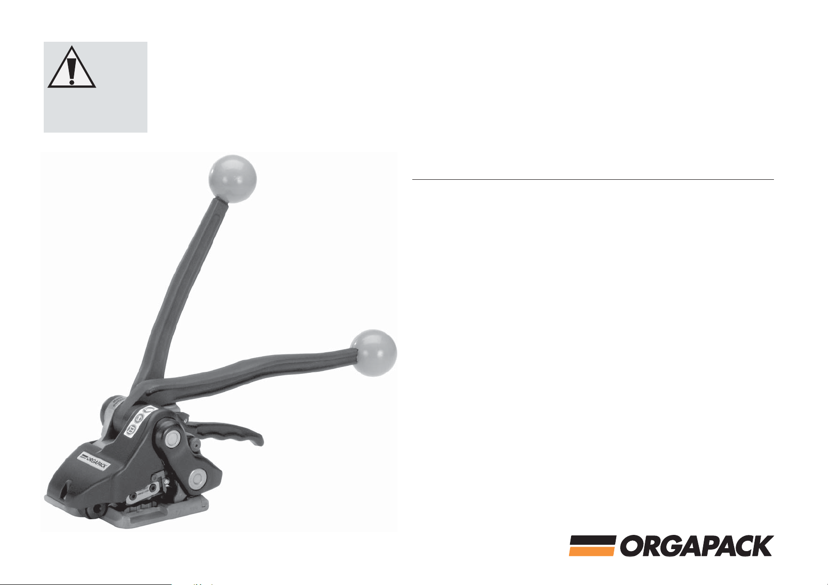
OR-H 47
Hand tool for steel strapping
09/07
ORGA
PACK OR-H 47
Table of contents
1 Technical data 3
2 General information
3 Safety instructions
4 Construction
5 Operating
6 Maintenance
6.1 Cleaning of the tool
6.2 Setting the cutting depth
6.3 Replacing wearing parts 10
7
Recommended spare parts
7.1
Parts list
Exploded drawing 15
1
Technical data
Weight
Dimensions
Tension force Up to approx. 6500 N
Sealing Sealless notched
joint
Steel strap
Strap width 13, 16, 19 mm
Strap thickness
T
ensile strength
3.5 kg ( 7.7 lbs)
L = 370 mm (14.5")
W
= 185 mm (7.27")
H = 122 mm (4.79")
1
5
(
",
",
/
/
2
8
0,38–0,63 mm
(.014"–.025")
650– 1
100 N/mm
5
12
12
3
")
/
4
2
General information
These operating instructions contain
important information concerning the
4
6
7
9
9
9
2
safe, proper and efficient use of the
strapping tool. Compliance with the
instructions will help to avoid danger,
reduce repairs and stoppages and
increase the reliability and service life
of the strapping tool.
In addition to the operating instructions
and the regulations for accident prevention effective in the country of use
and place of application, the recognized technical regulations for safety
and proper working must also be observed.
Use for the intended purpose
a)
This tool is designed for strapping
packages, pallet loads etc.
This tool was designed and manufactured for safe handling during the strapping operation.
The tool processes steel straps only.
b) Possible misuse
Plastic straps cannot be used.
c) Information on environmental
protection
This tool is manufactured with no physical or chemical substances that could
be dangerous to health.
For disposal of all the parts, the
governmental instructions must be
observed.
3
Safety instructions
Inform yourself!
1.
Before using the tool read the operating instructions carefully.
Protect yourself!
2.
When operating the tool, wear eye-,
face- and hand protection (cutting
protected gloves).
Only strap packed goods!
3.
Do not put hands or other parts of
the body between the strap and the
package.
Strap will snap forward when
4.
cutting!
When cutting the strap, hold the
upper portion and stand a safe
distance away from the strap.
Caution:
forward.
5. Strap could break during
tensioning!
Do not stand in line with the strap
while it is tensioned. The strap could
break!
Danger of squeezing!
6.
Do not put your fingers into the
tension wheel area.
7. Original ORGAPACK spare parts!
Only original ORGAPACK spare
parts may be used.
the lower strap will snap
jklsfjklsdjš
lksdfjkl
jkljsdllkjjkljsd
fkljjklkjkljsdafj
asdfjklkjjkljklj
ksldafkjkljklš
jkljklkljsdafjlkj
jkljjkljklkljljlk
1.
.
3
.5 6.
Original
ORGAPACK
.7
2.
.
4
Page 2 of 7
09/07
ORGA
PACK OR-H 47
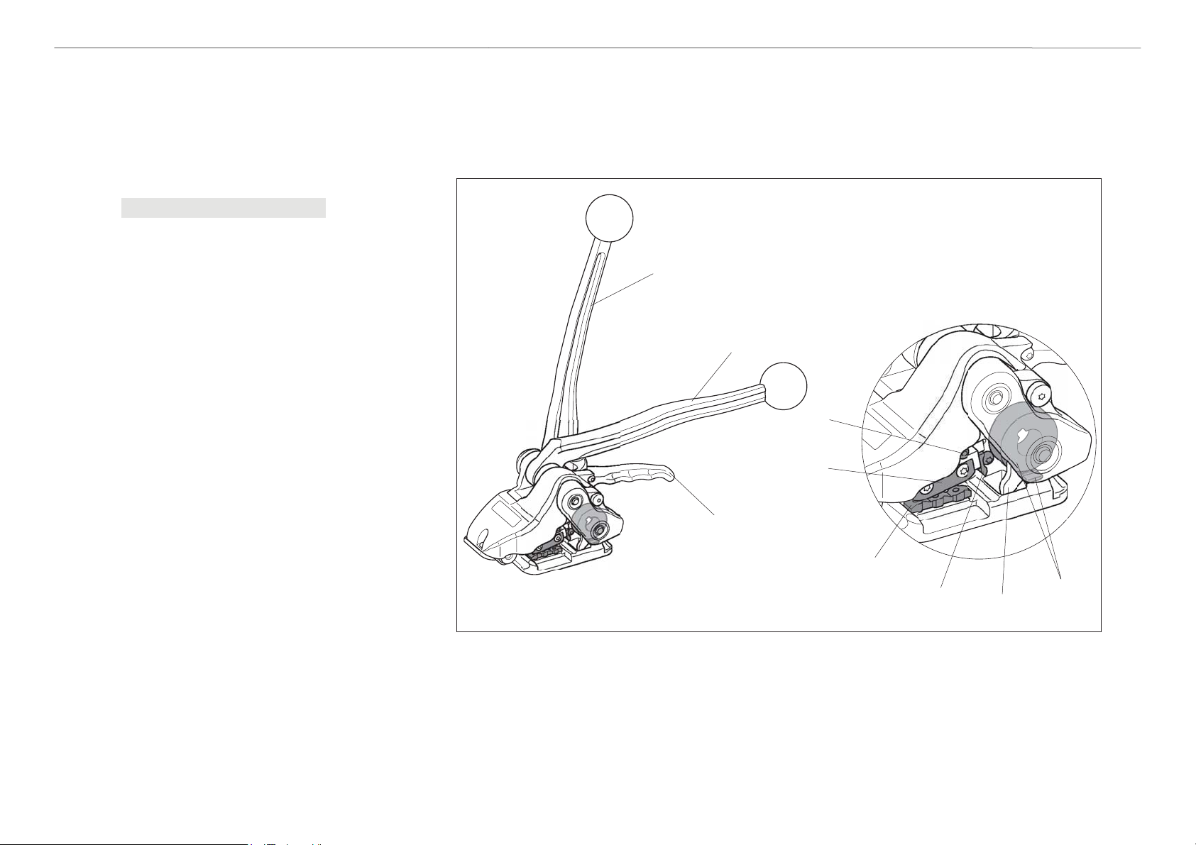
4
Construction
1. Tensioning lever
2. Sealing lever
3. Rocker lever
4. Tension wheel and tension plug
5. Strap guide pawl
6. Cutter knife
7. Die
8. Punch
Adjusting screw (cutting depth)
9.
Fig. a
1
2
9
8
3
7
6
5
4
Page 3 of 7
09/07

ORGA
PACK OR-H 47
5
Operating
Fig. 1
– Place strap round packed goods
(Fig. 1/1), so that the straps lie
above each other on top of the
package.
Fig. 2
– Hold tool in right hand and raise
rocker lever (Fig. 2/1) against
sealing lever (2/2).
– Place tool against the strap until it
contacts the stop.
– Release rocker lever.
–
Strap can now be manually preten-
sioned.
Fig. 3
–
Hold sealing lever (Fig. 3/1) in left
hand and with the right hand move
the tensioning lever (3/2) backwards
and forwards until the required strap
tension is obtained.
Fig. 1
Page 4 of 7
Fig. 2
2
1
1
F
ig. 3
2
1
09/07

ORGA
Fig 4.
1
PACK OR-H 47
Fig. 4
– When the strap tension is reached,
move sealing lever (Fig. 4/1) to the
stop.The right hand remains on the
tensioning lever to resist the opposing force. The strap is sealed and
cut.
If the strap cut is incorrect (see
chapter 6.2).
Fig. 5
– Return sealing lever to initial position.
– Raise the rocker lever against the
sealing lever.
– Swivel the tool away from the
strapping backwards and to the
right.
Seal check
Fig. 6
T
o obtain the maximum seal efficiency,
the notches must be cut and interlocked properly into the straps: Check
this regularly. If these notches are not
correctly cut, replace die and tension
plug (see chapter 6.3).
Page 5 of 7
F
ig. 5
. 6
Fig
ca. 1 mm (.039")
.
09/07

ORGAPACK OR-H 47
6
Maintenance
6.1 Cleaning the tool
The tool should be regulary cleaned.
The tension wheel and the tension
plug, in
The easiest way to do this, is to use
compressed air to blow out the dust.
Wear eye protection.
Periodically lubricate all moving parts
with one or two drops of light machine
oil.
particular,should
be kept clean.
6.2 Setting the cutting depth
The setting of the cutting depth must
correspond to the thickness of the relevant strap. If set incorrectly, the sealing
strength may be reduced.
– Set adjusting screw marked in red
(Fig. 7/1) with screwdriver (Torx).
– Turning adjusting screw clockwise:
increases cutting depth.
– Turning adjusting screw
counterclockwise:
decreases cutting depth.
Set cutting depth so that the lower
strap is not touched during cutting.
.
6.3
Replacing wearing parts
a)
Replacing die
–
Release tallow-drop screw (8/16).
–
Raise die (8/93) with screwdriver,
remove and replace it .
b)
Replacing punch complete
–
Release screws (8/21), remove and
replace punch complete (8/93).
Fig. 7
c)
Replacing cutter knife
–
Release tallow-drop screw (8/8) and
remove and replace cutter knife
(8/20).Adjust the setting depth after
replacement ( refer to chapter 6.2).
d)Replacing tension plug
– Release two counter sunk screws
(8/35).
–
Remove tension plug support (8/30).
–
Remove and replace tension plug
(8/34).
+
1
Fig. 8
Page 6 of 7
93
(Loctite 222)
16
93
21
20
8
(Loctite 222)
34
(Loctite 222)
35
30
09/07

ORGA
PACK OR-H 47
e) Replacing tension wheel
– Release shoulder screw (9/64).
– Lift rocker lever and remove bearing
– Remove distance washer (9/58),
– Remove and replace tension wheel
– During installation, observe strap
Fig. 9
cover (9/61).
strap guide pawl (9/59) and dis
tance washer (9/58).
(9/57).
width adjustment (see Fig. 9).
Page 7 of 7
e)
57
58
59
58
16 mm (
61
5
")
/
8
19 mm (
3
)
"
/
4
1
")
(
mm31
/
2
80
64
09/07
 Loading...