

Organ recovery systems LifePort Kidney Transporter LKT100P Owner's Manual

LifePort Kidney Transporter
Operator’s Manual 1.0

This Operator’s Manual references
LifePort Kidney Transporter
Model Number: LKT100P
2460
For technical assistance and to reorder supplies
and single use disposables, please contact:
Organ Recovery Systems Organ Recovery Systems NV ORS Representacoes do Brasil Ltda.
One Pierce Place, Ste 475W DaVincilaan 2, Box 6 170 Moema Avenue, Suite 11 & 12
Itasca, IL 60143 1831 Diegem Sao Paulo, SP 04077-020
USA Belgium Brazil
T +1.847.824.2600 T +32.2.715.0000 T +55.11.3586.6259
F +1.847.824.0234 F +32.2.715.0009 F +55.11.3586.4944
Perfusion Helpline: Perfusion Helpline: Perfusion Helpline:
+1.866.682.4800 +32.2.715.0005 +55.11.98638.0086
www.organ-recovery.com
www.patents-organrecoverysystems.com
Emergo Europe
Prinsessegracht 20
2514 AP The Hague
The Netherlands
T +31.70.345.8570
F +31.70.346.7299
service@emergogroup.com
LifePort Kidney Transporter manufactured in the USA for Organ Recovery Systems.
LifePort Kidney Transporter Operator’s Manual 755-00029 Rev H

Retain the following in your records:
Institution___________________________________________________________________
Contact____________________________________________________________________
Model Number______________________________________________________________
Serial Number______________________________________________________________
Date of Purchase____________________________________________________________
755-00029 Rev H LifePort Kidney Transporter Operator’s Manual 3

Table of Contents
How To Use This Manual
Introduction………………………………………………………………………………………………………………7
Purpose of Manual………………………………………………………………………………………………………7
Abbreviations……………………………………………………………………………………………………………..8
System Description
Intended Use…………………………………………………………………………………………………………… 9
Safety…………………………………………………………………………………………………………………….9
Physical Description…………………………………………………………………………………………………… 9
Main Enclosure…………………………………………………………………………………………………….10
Ice Container……………………………………………………………………………………………………….10
Pump Deck…………………………………………………………………………………………………………10
Electronics…………………………………………………………………………………………………………..1 1
Control Panel……………………………………………………………………………………………………….11
Outer Display……………………………………………………………………………………………………….12
LifePort Disposables…………………………………………………………………………………………………..12
LifePort Perfusion Circuit (Cassette)…………………………………………………………………………….12
LifePort Disposable Cannulas…………………………………………………………………………………….13
LifePort Sterile Drape………………………………………………………………………………………………13
Operational Accessories………………………………………………………………………………………………13
Power Cord………………………………………………………………………………………………………...13
Batteries……………………………………………………………………………………………………………..13
Battery Charger (Optional)………………………………………………………………………………………..14
Data Cable…………………………………………………………………………………………………………..14
Perfusion Mode………………………………………………………………………………………………………..14
Label Graphics Explanations……………………………………………………………………………………..15
Safe Disposal of LifePort Batteries……………………………………………………………………………….15
Unpacking, Setup, and Preliminary Testing
Overview………………………………………………………………………………………………………………...16
Introduction……………………………………………………………………………………………………………..16
Selecting a Home Base Station………………………………………………………………………………………16
Unpacking and Inspecting…………………………………………………………………………………………….16
Running Preliminary Tests…………………………………………………………………………………………….17
Setting Up the LifePort…………………………………………………………………………………………………17
Filling the Ice Container……………………………………………………………………………………………..17
Loading the Perfusion Circuit (Cassette)……………………………………………………………………….....17
Energizing the LifePort……………………………………………………………………………………………...18
Testing Operating Modes…………………………………………………………………………………………...19
Testing the Batteries……………………………………………………………………………………………….19
Checking Duration of Operation (Optional)……………………………………………………………………..20
Setting up External Communications using Data Station……………………………………………………..20
Cleaning Up and Review after Use……………………………………………………………………………...21
LifePort Kidney Transporter Operator’s Manual 755-00029 Rev H
4

Using the LifePort
Introduction……………………………………………………………………………………………………………..22
Professional Overview…………………………………………………………………………………………………22
Maintaining the LifePort for Quick Response Use………………………………………………………………….22
Preparing the Home Base Station………………………………………………………………………………..22
Preparing the LifePort for Recovery………………………………………………………………………………….23
Cooling Down the LifePort………………………………………………………………………………………............23
Traveling with the LifePort and Supplies………………………………………………………………………...24
Setting Up the Kidney Perfusion Circuit (Cassette)…………………………………………………………….24
Isolating the Kidney Vascular Structure……………………………………………………………………………...26
Cannulating the Kidney………………………………………………………………………………………………..27
Using the Straight Cannula………………………………………………………………………………………..27
®
Using the SealRing
Cannula……………………………………………………………………………………..28
Using the Coupler…………………………………………………………………………………………………..30
®
Using the Universal SealRing
………………………………………………...…………………………………..32
Placing the Kidney in the LifePort……………………………………………………………………………………33
Priming the Infuse Line………………………………………………………………………………………………. 35
Preliminary Testing for Leaks……………………………………………………………………………………..36
Initiating Perfusion………………………………………………………………………………………………….37
Checking the Kidney After Placement……………………………………………………………………………….37
Visual Inspection……………………………………………………………………………………………………37
Cannula Leakage?……………………………………………………………………………………………..37
Artery Filled?…………………………………………………………………………………………………….37
Side Branches Closed?……………………………………………………………………………………….. 37
Vein Positioned on Top?……………………………………………………………………………………….38
Presence of Blood or Perfusate?……………………………………………………………………………..38
Color of Kidney?………………………………………………………………………………………………..38
Closing the LifePort……………………………………………………………………………………………………38
Monitoring Options for a Kidney on the LifePort……………………………………………………………………39
Monitoring via LifePort Outer Display…………………………………………………………………………....39
Data Station Monitoring……………………………………………………………………………………………41
Typical Behavior of a Kidney on LifePort……………………………………………………………………………42
Leakage at Cannula or Open Side Branch……………………………………………………………………...42
Nonresponding Kidney…………………………………………………………………………………………….43
Remote Monitoring…………………………………………………………………………………………………43
Preparing to Travel to the Transplant Site…………………………………………………………………………. 43
Delivering to the Transplant OR…………………………………………………………………………………….. 43
Checking Battery Power and Ice………………………………………………………………………………... 43
Adding More Ice………………………………………………………………………………………………..44
Replacing Batteries…………………………………………………………………………………………….44
At the Transplant OR……………………………………………………………………………………………... 44
Waiting until Recipient Surgery Is Ready……………………………………………………………………………44
Removing the Kidney from the LifePort for Transplant…………………………………………………………….45
Downloading Operational Data (optional)…………………………………………………………………………..48
Introduction………………………………………………………………………………………………………….48
755-00029 Rev H LifePort Kidney Transporter Operator’s Manual 5

Troubleshooting and Diagnostics
Troubleshooting Procedures………………………………………………………………………………………….49
Error Message Explanations………………………………………………………………………………………….50
Power On Self Test (POST)………………………………………………………………………………………….. 53
Maintenance
Overview………………………………………………………………………………………………………………...54
Cleaning Up after a Case…………………………………………………………………………………………….. 54
Storage………………………………………………………………………………………………………………….54
Shipping by Common Carrier…………………………………………………………………………………………55
Specications, Precautions, Limitations
Product Specications…………………………………………………………………………………………………55
Device Classications………………………………………………………………………………………………….56
Electromagnetic Compatibility………………………………………………………………………………………...56
Operational Precautions and Limitations…………………………………………………………………………….60
Hazards
Overview………………………………………………………………………………………………………………...62
LifePort Kidney Transporter Operator’s Manual 755-00029 Rev H
6

How To Use This Manual
Introduction
It is important that all personnel who will operate the LifePort Kidney Transporter (LifePort):
• Read and understand this manual before operating the LifePort.
• Follow all warnings and precautions outlined in the sections Specications, Precautions and
Limitations on page 55, and Hazards on page 62 for their own safety and the safety of those
around them.
The LifePort is intended to be used for the hypothermic machine perfusion of kidneys. If more information
is needed about installation, organ perfusion, or if you have any questions, please contact Organ
Recovery Systems Perfusion Helpline.
Purpose of Manual
The instructions within this manual should be carefully followed for safe, trouble-free, and effective
equipment use.
This manual provides the essential information necessary for installation, operation, and routine servicing
of the LifePort. It contains important operation and maintenance information for personnel who have been
trained in organ perfusion.
This manual is NOT to be used as a replacement for training in the art or science of organ perfusion.
This manual does NOT contain information for servicing internal components of the system.
In this manual, the following denitions apply for all WARNING and CAUTION statements.
WARNING: A warning statement covers any operation, procedure, practice, etc., which if not
strictly observed, might result in injury or long-term health hazards to personnel or patients.
CAUTION: A caution statement covers any operation, procedure, practice, etc., which if not
strictly observed, might result in damage or destruction of equipment or loss of treatment
effectiveness.
755-00029 Rev H LifePort Kidney Transporter Operator’s Manual 7

Abbreviations
The abbreviations used in this manual are listed and dened in the following table.
A Amperes
AC Alternating current
A-hr Ampere-hours
°C Degrees Celsius
cm Centimeter (1 cm = .01 m)
L Liter (1L =0.001 m3)
lb(s) Pound (1 lb = 0.45 kg)
LCD Liquid Crystal Display
LED Light Emitting Diode
kg Kilogram (1 kg = 2.2 lbs)
mL/min Milliliters per minute (1 mL/min = 0.00006 m3/sec)
mmHg Millimeters of mercury (1 mmHg = 1 Torr = 133.3 Pa)
V Volts
LifePort Kidney Transporter Operator’s Manual 755-00029 Rev H
8

System Description
Intended Use
The LifePort is intended for use in continuous hypothermic machine perfusion of kidneys.
Safety
The responsibility for safety when using LifePort resides within the healthcare professionals who use it.
The LifePort is safe when used as described in this manual. It is designed to meet recognized U.S. and
international standards for medical equipment and systems, as stated by the Underwriters Laboratories
and the International Electro-technical Commission.
Electrical and mechanical safety features have been designed into the LifePort to ensure safe operation.
These features are as follows:
• The electrical and electronic components are contained within a secure enclosure.
• Perfusate temperature, ow rates, and pressure levels are only adjustable within a set range,
which cannot be changed by the operator.
• Perfusate pressure, ow rate, and temperature are continuously monitored.
• A power indicator light is provided to indicate when the unit is powered on. Stop, Wash, Prime
and Infuse lights are provided to indicate whether the LifePort is stopped, washing, priming, or
infusing.
• Acceptable operating ranges are established within the LifePort for pressure, temperature, ow
rate, battery charge state, bubbles in the perfusate, and conguration integrity. Hard-wired and
software interlocks are built-in to bring the LifePort to a failsafe condition if an unacceptable
operating state is detected.
• An error light, audible alert and descriptive message are given by the LifePort if an unacceptable
operating state is detected.
Physical Description
The LifePort is a portable transport device designed to maintain a transplantable kidney under cold and
aseptic conditions, while perfusing it at the same time. An insulated, plastic housing encloses the kidney
and perfusate within a disposable Perfusion Circuit (Cassette). The LifePort’s components also include
an Ice Container, Pump Deck, four lithium-ion batteries, electronics, Bubble Detectors, a Control Panel,
and an Outer Display.
Ice Container
Ice Container
Ergonomic
Handles
Outer Display
Pump Deck
Bubble
Detectors
Infusion
Pump
Control Panel
Safety Latch
Insulating Cover
755-00029 Rev H LifePort Kidney Transporter Operator’s Manual 9
The LifePort is designed to integrate with the clinical environment by using readily available supplies,
requiring minimal user intervention, and by being easy to use.
Once the Ice Container is properly loaded, even when the LifePort is powered off, it preserves kidneys
hypothermically to the same degree as conventional static (ice-pack) storage methods.
Main Enclosure
The LifePort is enclosed in a rugged, insulated plastic housing designed for easy carrying. The lower
section contains an Ice Container, Perfusion Circuit (Cassette), Pump Deck, batteries, electronics,
sensors, Bubble Detectors, Control Panel, Outer Display, and Disposables. Two handles make the unit
easy to lift and carry.
An insulated, removable, latched Cover encloses the lower housing during perfusion to keep the kidney
secure and at the proper temperature.
Ice Container
The Ice Container is a sealed enclosure with a removable Lid, which is lled with a mixture of ice and
water to provide a stable cold temperature environment for the kidney.
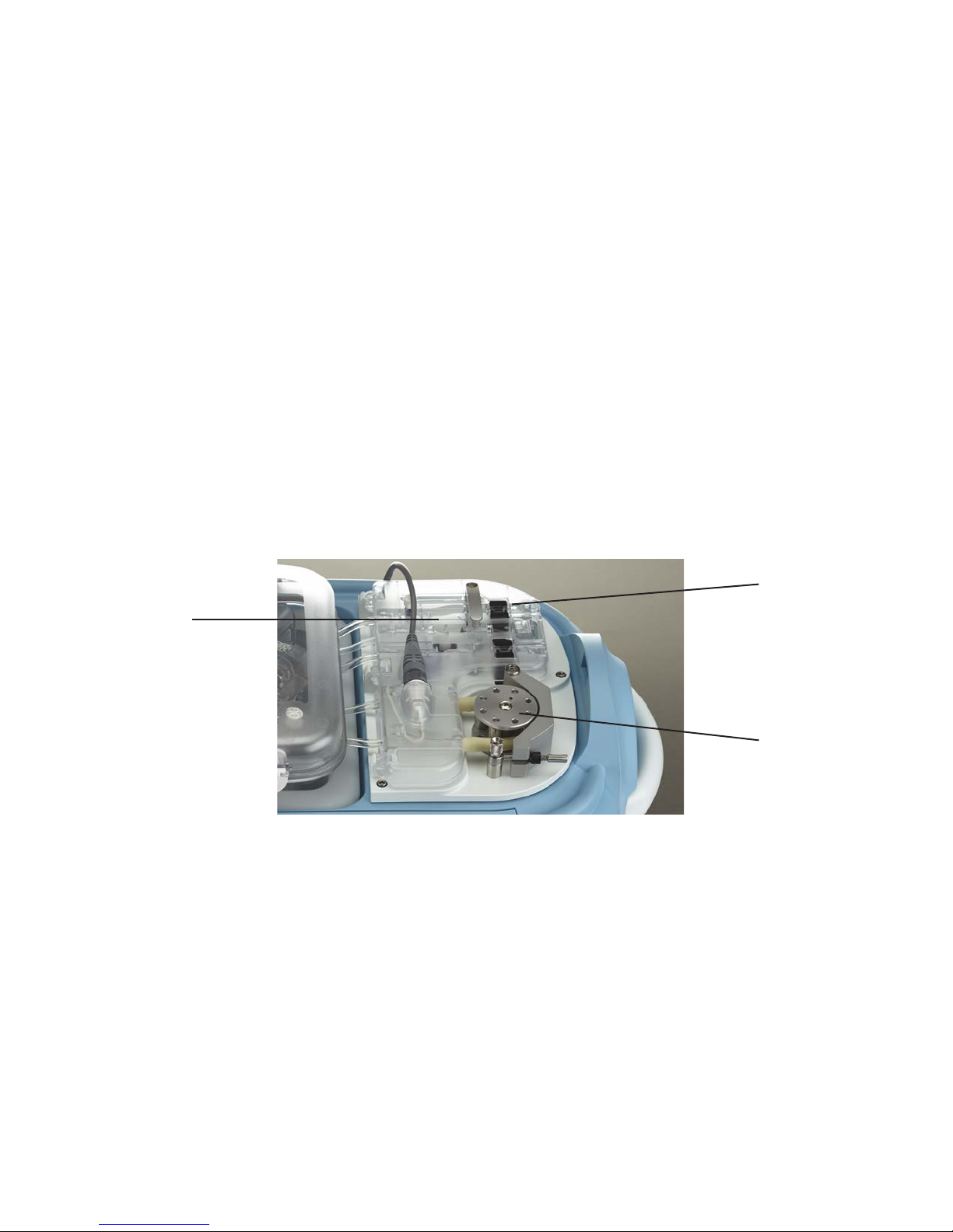
Pump Deck
The Pump Deck is the uid management area of the LifePort. On the Pump Deck, the Perfusion Circuit
(Cassette) tubing traverses a peristaltic pump, valves, and sensors, which control the pressure, speed,
and routing of the perfusate.
Bubble
Detectors
Pump Deck
Infusion Pump
• Infusion Pump — A peristaltic pump that propels perfusate through the kidney. By moving
rollers against the pump tubing, the Pump pushes the perfusate through the kidney, while
keeping it sealed within the Perfusion Circuit (Cassette). The LifePort electronics regulate pump
speed to control perfusion pressure.
• Bubble Detectors — Two non-contact Bubble Detectors on the Pump Deck check the
perfusate to prevent bubbles from entering the kidney.
The rst Bubble Detector is located upstream of the Bubble Trap and Wash Line, and diverts
detected bubbles away from the kidney and into the Wash Line, after which the LifePort will
resume perfusing.
The second Bubble Detector is located immediately before the kidney, and prevents detected
bubbles from entering the kidney by stopping perfusion altogether.
LifePort Kidney Transporter Operator’s Manual 755-00029 Rev H
10
• Pressure Sensor Cable — Provides the LifePort computer with information about the perfusion
pressure felt by the kidney. If the Pressure Sensor connection is broken, the LifePort stops and
displays an error message.
• The Infuse and Wash Valves — Determine whether the perfusate enters (Infuse Valve) or
bypasses (Wash Valve) the kidney. In INFUSE mode, the Infuse Valve is open and the Wash
Valve is closed, allowing perfusate to ow into the kidney. In WASH mode and during bubble
purge, the Wash Valve is open and the Infuse Valve is closed, directing the perfusate through
the bypass line, directly back into the perfusate reservoir. The valves are electrically activated.
Electronics
Electronic circuits control LifePort functions and user interactions, manage power, and enable
communications over standard computer interfaces. All circuits are contained within the LifePort
electronics module, and include:
• Computer
• Batteries and battery charger
• Communications interface
• Sensor interface
• Power supply (A hospital-grade power cord is supplied…do not substitute.)
• Pump and valve driver circuits
• Fan
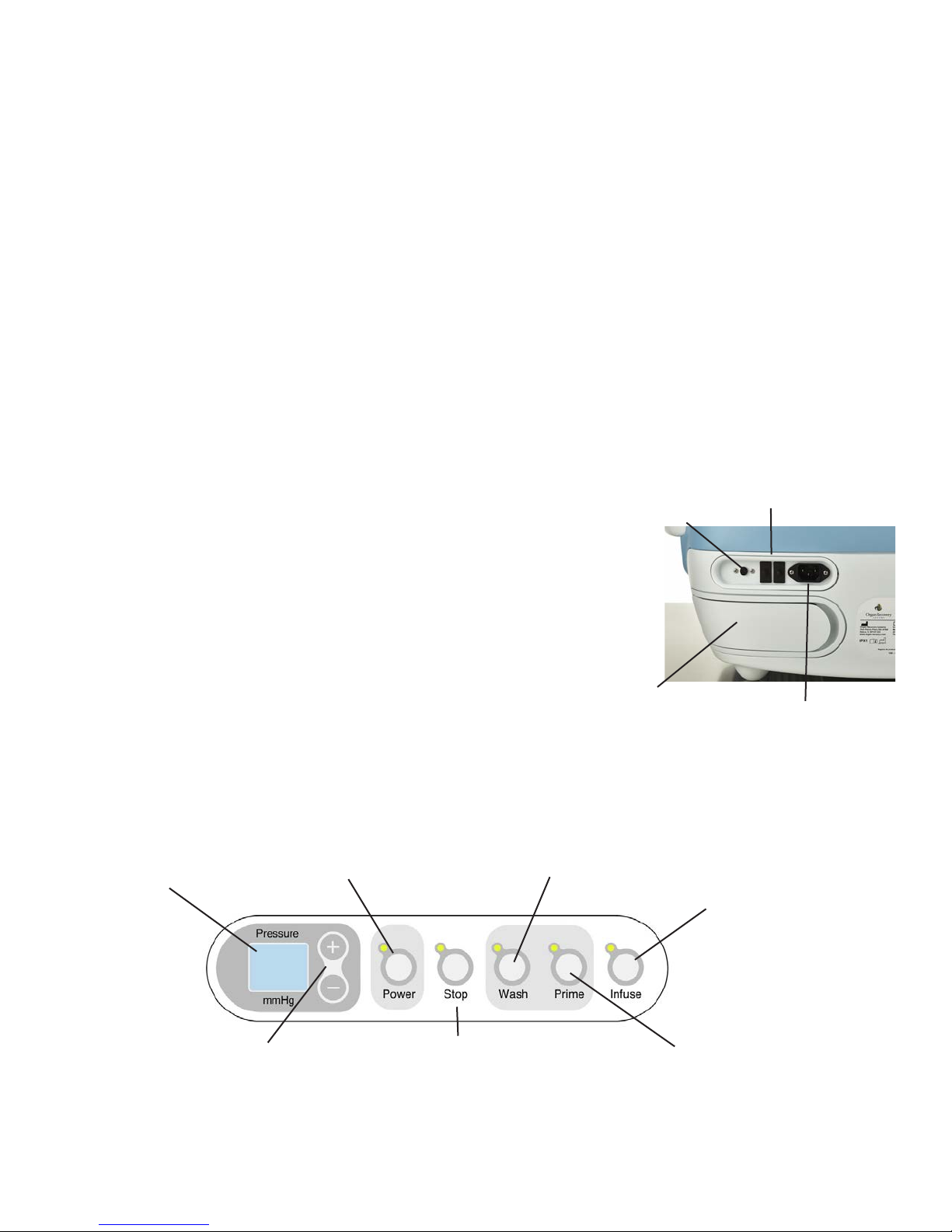
External Connections
The LifePort connects with an external power source and other
devices through its back panel, which provides a standard AC power
cord connector and a serial interface Data Port.
Data Port
Circuit Breakers
Circuit Breaker
Two circuit breakers, located on the back panel, trip if a short circuit
occurs. Depressing the button resets the breaker.
Batteries
Control Panel
The Control Panel is located next to the Pump Deck. The panel can be accessed only when the Cover is
removed, which prevents inadvertent and unauthorized access to the controls.
LEDs indicate when the Power, Stop, Wash, Prime, and Infuse modes have been selected.
WASH button
circulates without
perfusing kidney
INFUSE button
circulates
perfusate through
kidney at setpoint
pressure
PRIME button
clears air from
tubing prior to
perfusion
PRESSURE
Setpoint Display
PLUS/MINUS
buttons raise
and lower
infusion pressure
by 1-mmHg
increments
POWER
button
STOP
button
AC Plug
755-00029 Rev H LifePort Kidney Transporter Operator’s Manual 11
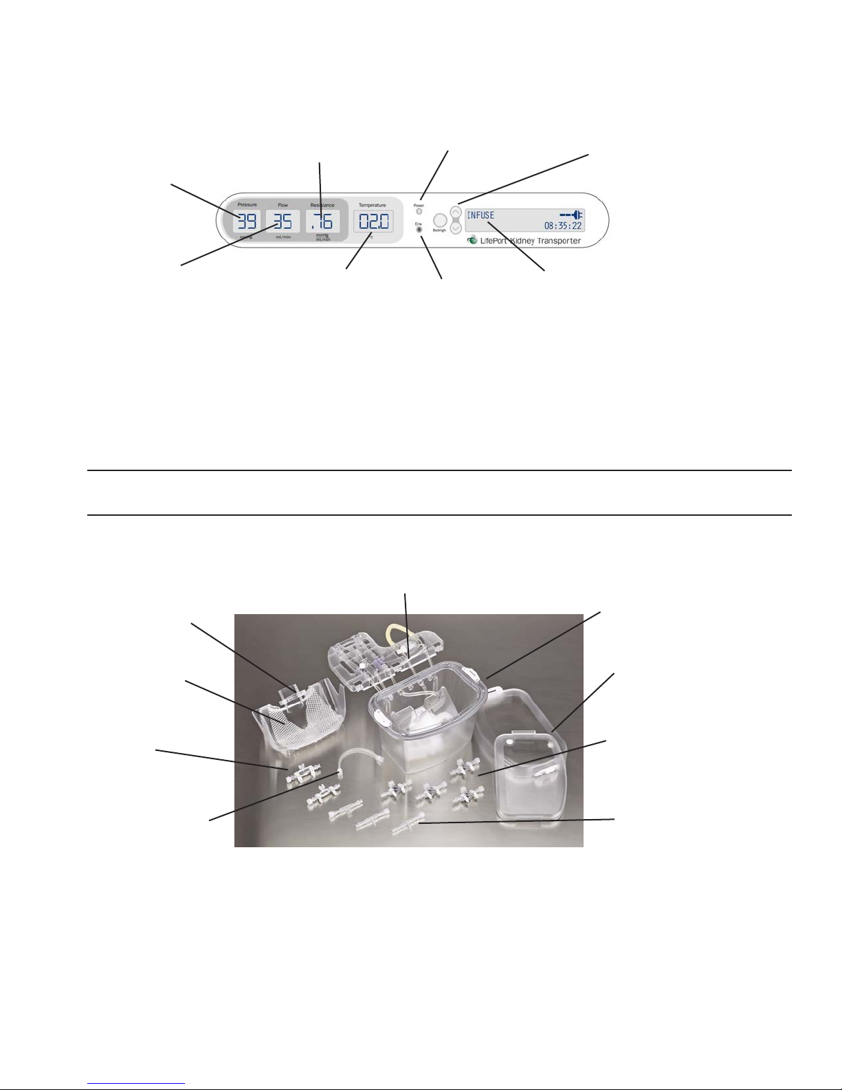
Outer Display
The Outer Display — a horizontal panel visible whether the Cover is in place or removed — provides
information on operational parameters as well as additional information about the perfusion history.
SYSTOLIC
PRESSURE from
10-65 mmHg
FLOW RATE
(volumetric)
entering renal artery
VASCULAR RESISTANCE
within the kidney
TEMPERATURE
within insulated cold
section
POWER
status indicator
ERROR
alert indicator
MESSAGE DISPLAY shows pump
best/min, diastolic press, average
press (pulsatile mode only), perfusate
temp, min/max temps reached, time of
day, data memory remaining, battery
power remaining
SCROLL buttons
to read displayed
messages
LifePort Disposables
Single-use Disposables, an integral part of the LifePort, are used to contain the kidney and perfusate
under aseptic conditions during transport, to connect the kidney to the Perfusion Circuit (Cassette),
and to help maintain aseptic conditions while working inside the Perfusion Circuit (Cassette). Each
Disposable is factory pre-sterilized and delivered in an easy-to-open sterile pack.
NOTE: To reorder Disposables, please contact Organ Recovery Systems. (See inside front cover for
contact details.)
The primary disposables are shown—separated for easier visualization—in the illustration below. A full
description follows.
Perfusion Circuit (Cassette) and Tubeframe
Perfusion Circuit (Cassette)
Cannula Mount
Inner/Outer
Kidney Cradle
SealRing
Coupler
Perfusion Circuit (Cassette)
Lids
Universal SealRing Cannula
Straight Cannula
LifePort Perfusion Circuit (Cassette)
Contains the uid management components necessary for perfusing a single kidney. The Perfusion
Circuit (Cassette) is comprised of:
• The PERFUSION CIRCUIT (CASSETTE) is the housing that contains the kidney. The kidney is
supported by the Kidney Cradle, and held in place by the Mesh Organ Restraint.
LifePort Kidney Transporter Operator’s Manual 755-00029 Rev H
12

The watertight Organ Cassette acts as the perfusate reservoir, where the kidney is
maintained partially submerged. A transparent sterile Inner Lid and transparent Outer Lid
provide a redundant watertight seal.
The Organ Cassette has Infuse, Wash, and Return ports that mate with the Perfusion Circuit
(Cassette). Inside the Perfusion Circuit (Cassette), the Infuse Line continues and terminates
with a male Luer tting, which connects to the cannula.
• The PERFUSION CIRCUIT (Cassette) is the sealed uid path that draws from the perfusate
bath and delivers perfusate into the kidney. The Perfusion Circuit (Cassette) is comprised of:
• Tubeframe, which positions the tubing per the pump, valves, and sensors of the Pump
Deck, and simplies attaching the Perfusion Circuit (Cassette) to the Pump Deck.
• Bubble T rap, located on the Tubeframe to help keep air from entering the Infuse Line.
• Infuse, Wash, and Return Lines located on the Tubeframe to manage perfusate ow.
• Pump T ubing Loop, extending from the Tubeframe and stretched around the Infusion
Pump Head. Sample Port, protruding from the top of the Tubeframe, provides access to
sample perfusate or inject uids without opening the Perfusion Circuit (Cassette).
• Pressure Sensor and Connector, a ow-through pressure sensor within the Infuse line
that measures perfusate pressure within the Circuit. Connects to the Pump Deck
Pressure Sensor Cable and sends pressure data to the internal computer.
• Filter, located under the Perfusion Circuit (Cassette), collects material that could block
kidney vasculature from achieving proper ows.
• Compliance Chamber, located under the Perfusion Circuit (Cassette), helps maintain
steady perfusion pressures.
LifePort Disposable Cannulas
LifePort Disposable Cannulas attach the Perfusion Circuit (Cassette) to the kidney’s renal artery. A
large range of cannula types and sizes are available, making it possible to choose the cannula most
compatible to the anatomy of the kidney: large artery, multiple arteries, or plaque on artery (with or
without the aortic cuff).
LifePort Sterile Drape
The Sterile Drape is used to aid in maintaining aseptic conditions while working within the Perfusion
Circuit (Cassette).
Operational Accessories
In operation, the LifePort uses special accessories and supplies. To work properly, it is important to
use only accessories and supplies provided by Organ Recovery Systems or from vendors identied as
compatible with the LifePort.
Power Cord
The LifePort comes equipped with a Power Cord (hospital grade), which can be connected to the LifePort
back panel and to a standard grounded power outlet of commercial or hospital quality. Do not substitute
an alternate Power Cord.
Batteries
The LifePort uses four specially designed lithium-ion rechargeable batteries as its portable source
of power.
CAUTION: Do not substitute batteries. Use only LifePort batteries (SM201-6) from Organ Recovery
Systems. For information, contact the Organ Recovery Systems Perfusion Helpline.
755-00029 Rev H LifePort Kidney Transporter Operator’s Manual 13

The LifePort draws power from one at a time, using the batteries in series. Therefore, it is possible to
operate with any number from one to four batteries, since each delivers the 1 1 to 12 volts required.
However, it is recommended to use all four batteries, which you should keep as fully charged as possible.
NOTE: There are two ways to verify a battery’s charge:
1. By pressing the battery’s ON button and observing the display located on each battery.
2. By pressing the SCROLL buttons to scroll the Message Display.
Access the batteries through the Battery Door on the LifePort rear panel. Each battery can be slid in and
out of its slot. When inserted in the proper orientation, the battery should be ush with the slot panel, with
the fabric-pull visible and available for removing the battery. If the battery does not push ush, it may be
in the wrong orientation. Turn the battery 180 degrees and try again. The following tips will help you
obtain maximum life and serviceability from the batteries.
• Always replace the Battery Door. The LifePort should not be operated or shipped without the
Battery Door in place.
• The LifePort’s built-in charger will replenish the batteries whenever the LifePort is plugged into
an external power supply. It’s a good idea to plug in the LifePort whenever not in transit, keeping
the batteries at the highest possible charge. Normally, it takes ve hours to completely recharge
all four batteries.
NOTE: Keep spare charged batteries handy for long transportations or successive LifePort uses.
• During storage of the LifePort without connection to an external power supply, the batteries
will slowly drain. After 30 days the batteries could have little or no charge and will need a full
ve-hour recharge.
• For periods of storage for longer than 30 days, remove the batteries from the LifePort.
NOTE: Long periods of storage may damage the batteries.
• Lithium-ion batteries must be disposed of according to local regulations. If in doubt, consult
Organ Recovery Systems Perfusion Helpline.
Battery Charger (optional)
In addition to charging installed batteries by connecting the LifePort to an external power supply, you
can use an optional Battery Charger to charge them separately. This enables you to maintain a supply of
spare charged batteries. The Battery Charger is available from Organ Recovery Systems.
1. Plug the Battery Charger into an external power supply.
2. Insert the batteries into their respective slots and charging begins.
NOTE: A charge state indicator displays when the batteries are fully charged.
Data Cable
The Data Cable is a 6-ft (2m) cable used to connect the LifePort to an external computer. The round
end connects to the Data Port on the LifePort, and the opposite end connects to a 9-pin serial port of a
personal computer. A Serial-to-USB converter (not included) may be necessary for computers without
9-pin serial ports.
Perfusion Mode
The LifePort is available in Pulsatile mode. Mode is indicated in the LifePort Model Number found on the
label on the back of the device:
• LKT-100-P (Pulsatile mode) — A LifePort set to run in Pulsatile mode will pulse the pressure at a
xed pulse repetition rate to a systolic pressure set by the user on the Control Panel. The diastolic
pressure is determined in response to the kidney vascular resistance. The diastolic pressure can be
found on the Message Display.
LifePort Kidney Transporter Operator’s Manual 755-00029 Rev H
14
Label Graphics Explanations
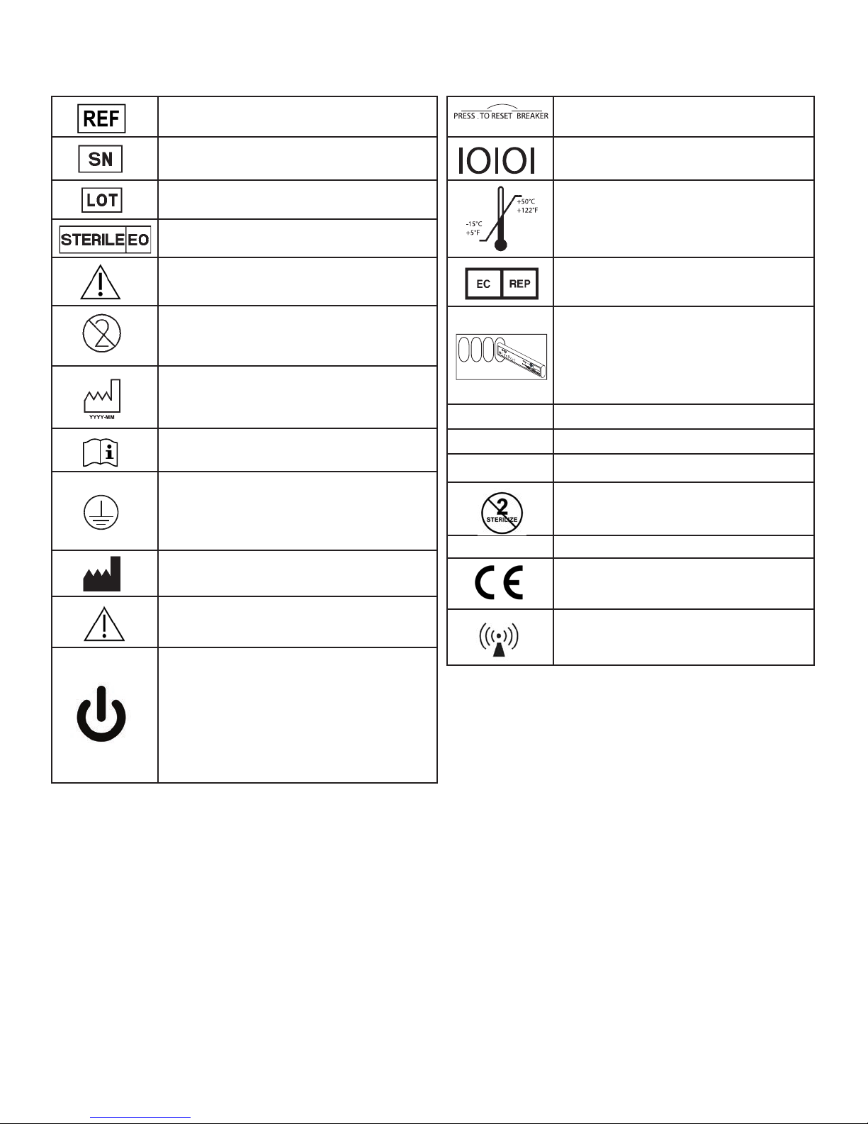
The following table provides an explanation of the label graphics found on the LifePort.
Reference Model Number
Serial Number
Lot Number
Sterile, method is ethylene oxide
CAUTION! Consult Accompanying
Documents
Do not reuse. Risk of contamination,
infection or potential serious hazard if
single use is not followed
Date of Manufacture
Consult Instructions for Use
To assure grounding reliability,
equipment should be connected to
a power system of commercial or
hospital quality.
Circuit breaker, push to reset
Data Port, RS232 Serial Data
Storage Condition: Temperature
EU Authorized Representative
Battery Slot Graphic showing slot
numbering and insertion orientation.
1 2 3
REPLACE ONLY WITH
BATTERY MODEL SM 204
Replace batteries only with
manufacturer’s battery model
SM201-6
IPX1 Protected against falling water
V~ VAC – Voltage AC
A Amp
Do not resterilize
Hz Hertz
Manufacturer
European Conformity Mark
(CE) Mark
WARNING!
Interference may occur in the
vicinity of equipment
Power button-standby power. When
on mains power, this button turns
LifePort on and off, however the
battery charging and power supply
fan remain on at all times. When on
battery power, LifePort is completely
powered off.
Safe Disposal of LifePort and LifePort Batteries
For safe disposal of your LifePort Kidney Transporter or the LifePort batteries (SM 201-6) you may
return them to Organ Recovery Systems. You can call the Organ Recovery Systems Perfusion Helpline
to arrange for pickup from your facility, or return them directly to Organ Recovery Systems.
See information on page 2.
755-00029 Rev H LifePort Kidney Transporter Operator’s Manual 15

Unpacking, Setup, and Preliminary Testing
Overview
This section provides information for use upon receiving, unpacking, setting up, and preliminarily testing
the LifePort. The instructions provided in this section are to be performed one-time only. Routine
operating instructions are provided in the section titled Using the LifePort on page 22.
Introduction
The LifePort is shipped in a special container that is marked for appropriate handling. It should be
opened and checked only by a responsible person trained and qualied in working with electronic
medical equipment.
Selecting a Home Base Station
A home base station should be designated for each LifePort where it can be set up and recharged
between cases. The home base station should be a secure area and provide a clean bench top or
tabletop space. The following facilities and utilities are required:
• Climate controlled 24 hours a day to standard ofce or laboratory conditions (approximately
21°C, 50% humidity).
• No direct sunlight.
• AC electrical outlets (2 to 4 plugs: 120V/15A in the USA).
• Storage for LifePort disposables, batteries, tools, and spares.
• Space to place the LifePort Cover when it is removed.
• Easy access to crushed or cubed ice (hollow cubes not recommended).
• Easy access to a sink for clean-up and to provide water for the ice bath.
• Easy access to medical waste disposal.
• Easy access to refrigerated storage for perfusate and other medications.
• Tabletop space for Battery Charger and computer (recommended).
• Serial (RS232) connection for computer (recommended).
• Storage for transplant coordinator gear: cart, bags, procedure kits, and coolers.
• Proximity to operating rooms and ready access to car, ambulance, or helicopter loading areas.
Unpacking and Inspecting
Carefully remove the LifePort and its accessories from the Shipping Container. Save the packing
materials for shipping and storage.
After unpacking, thoroughly inspect the system and all accessories for damage. During this inspection,
ensure that:
• The LifePort housing is not bent or distorted.
• There are no dents, chips, or cracks in the housing surface.
• Manual controls and movable parts, such as connectors, operate properly.
• Control Panels are properly aligned.
• All items listed on the shipping documents are present.
Report any damage found from this inspection to the carrier immediately. If you have any concerns about
the condition of the LifePort or accessories, contact Organ Recovery Systems Perfusion Helpline.
LifePort Kidney Transporter Operator’s Manual 755-00029 Rev H
16
Running Preliminary Tests
Perform the following trial run with the LifePort to make sure that it is working properly. After each step,
observe the system to make sure that it functions as described and that there are no malfunctions, leaks,
or irresolvable errors. If difculties arise during setup and checkout, refer to the section titled
Troubleshooting and Diagnostics on page 49.
Setting Up the LifePort
CAUTION: The LifePort weighs 45 lbs (20.9 kg) fully loaded. Use proper lifting procedures to
avoid injury.
1. Holding the handles, lift the LifePort and place on its home base station table or countertop so that
the Outer Display is easily accessible and facing you.
2. Unlatch and remove the LifePort Cover, and store it nearby.
3. Complete your review of the LifePort — making sure that it is complete, secure and intact, and that
nothing appears broken — before starting these tests.
Filling the Ice Container
1. Open the Ice Container Lid and ll it with crushed or cubed ice, making sure to push the ice as far as
possible into the ice bath.
2. Pour about 1.0 Liter of cold water (less than 10°C) into the Ice Container, which will gradually loosen
the ice.
3. Add more ice and another 0.5-1.0 Liter water until the Ice Container is lled with an ice and water
mixture, maximizing the amount of ice added.
4. Close and lock the Ice Container Lid.
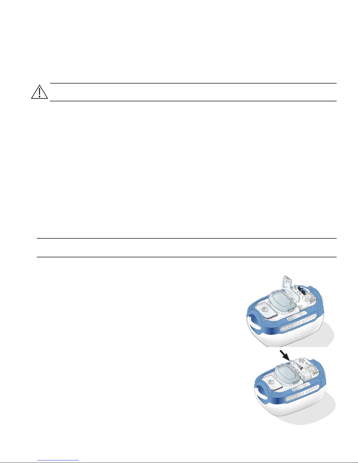
Loading the Perfusion Circuit (Cassette)
NOTE: For detailed instructions, refer to the document LifePort Kidney Perfusion Circuit (Cassette)
Instructions For Use (IFU).
1. Unpack a sterile Perfusion Circuit (Cassette) and assemble the
Circuit into the LifePort, positioning and securing the Tubeframe on
the Pump Deck so that the tubing mates properly with the Pump,
valves, and sensors.
2. Place the sealed Perfusion Circuit (Cassette) in the Ice Container.
The Tubeframe must be perpendicular to the Pump Deck, and
the hinges must be positioned inside of the receivers on the
Pump Deck.
3. Rotate the Tubeframe at onto the Pump Deck.
4. Open the Pump Head and stretch the tubing over the wheel.
Step 3
Step 4
755-00029 Rev H LifePort Kidney Transporter Operator’s Manual 17
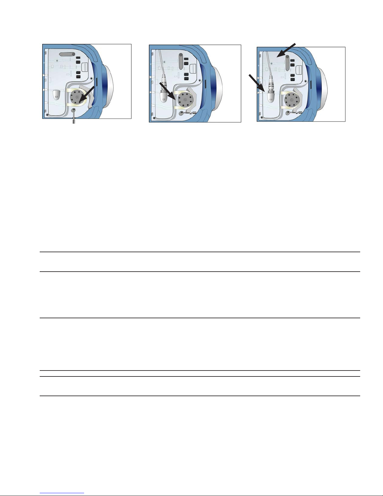
5. Close and latch the Pump Head Loop to clamp the tubing.
6. Rotate the Pump Deck Locking Arm 90° and snap into place.
7. Connect the Pressure Sensor Cable from the Pump Deck to the connector on the Tubeframe.
8. Remove the Inner and Outer Cassette Lids and pour 1 Liter of cold (less than 10°C) saline into the
Cassette housing.
9. Replace the Inner and Outer Cassette Lids.
Energizing the LifePort
1. Connect the Power Cord to the LifePort back panel, and plug it into an external power supply.
2. Press the POWER button:
• On the Control Panel, observe the following:
• The Power LED should illuminate
• The Pressure Set Point Display on the control panel should show a default value of
30 mmHg
• On the Outer Display Panel, observe the following:
• The message display screen should briey ash ***Power up self test***
Step 5
Step 6
Step 7
NOTE: If the LifePort detects any errors during its power on self-test, the rst line of the message display
will say Power up test FAILED and the second line will provide the name of the error.
• The LCDs on the outer display panel should show normal values as follows:
• The PRESSURE LCD should show double zeros (00)
• The FLOW and RESISTANCE LCDs should display a double dash (- -)
• The TEMPERATURE LCD should display the ice bath temperature
NOTE: It is common that the temperature of the LifePort will be high when rst energized. When the
ice bath temperature is above 8°C, the LifePort will beep, the red ERROR LED will illuminate, and the
second line of the message display will indicate Check Ice. If this happens, push the STOP button to
temporarily silence the audible alert. Then make sure that the Ice Container is properly lled and in
position. After installation of the Ice Container, it may take several minutes before the display reads a
temperature below 8°C.
NOTE: It is possible to run the LifePort in WASH mode in spite of the Check Ice error. However, PRIME
and INFUSE modes are not functional until the temperature is below 8°C.
• The top line of the message display should indicate READY.
Other errors may also occur at power on. If they do, refer to the section titled Troubleshooting and
Diagnostics on page 49 for information on how to proceed.
LifePort Kidney Transporter Operator’s Manual 755-00029 Rev H
18

Testing Operating Modes
1. Close and latch the Pump Head Loop to clamp the tubing.
2. Rotate the Pump Deck Locking Arm 90° and snap into place.
3. Connect the Pressure Sensor Cable from the Pump Deck to the connector on the Tubeframe.
4. Remove the Inner and Outer Cassette Lids and pour 1 Liter of cold (less than 10°C) saline into the
Cassette housing.
Replace the Inner and Outer Cassette Lids.
1. Press the pressure PLUS/MINUS buttons and verify that the pressure setpoint changes up or
down by 1 mmHg with each press.
2. Using the PLUS/MINUS buttons, set the pressure to 40 mmHg.
3. Press the WASH button and verify pump rotation.
4. Verify that perfusate is drawn from the Perfusion Circuit (Cassette), into the Pump, and then
down into the lter.
NOTE: Within a couple of minutes, perfusate should ow out of the lter, into the Bubble
Trap, then
into the wash port of the Perfusion Circuit (Cassette).
5. Verify that perfusate is contained within the tubing without leaks, and is not owing through the
Infuse Line into the Perfusion Circuit (Cassette).
6. Press the STOP button.
7. Press the PRIME button and observe that the ow diverts into the Infuse Line of the Perfusion
Circuit (Cassette).
a. Verify that perfusate is contained within the tubing without leaks, and is owing only
into the Infuse Line of the Perfusion Circuit (Cassette) (and not into the Wash Port).
b. Remove the Perfusion Circuit (Cassette) Lids and squeeze or clamp the Infuse
Tubing. The Transporter should beep, the Pump should stop, and the message dis
play should read: Stopped – Check Tubing.
c. Release the tubing and press the STOP button, which should clear the error
message.
8. Attach the Flow Restrictor onto the Luer tting on the Infuse Tubing (a 20-ga. or smaller syringe
needle will also work).
9. Press the INFUSE button. The pump should start up and begin regulating pressure toward the
setpoint level.
10. Verify that a ow rate and a vascular resistance are displayed on the front panel.
11. Press the STOP button to end the infuse test.
12. Turn the LifePort off by pressing the POWER button.
13. Verify that the power indicator is ashing green, which indicates the batteries are being charged.
Testing the Batteries
1. Open the LifePort Battery Door by sliding it away from the product label.
2. Insert the batteries.
3. Replace the Battery Door.
NOTE: The Battery Door should be in place whenever the LifePort is operated or transported.
Allow the batteries to charge for at least ve hours. Fully charged batteries should be ready to run
the LifePort for 24 hours.
4. Re-run the ENERGIZE and TEST OPERATING MODES tests as described above, using battery power.
NOTE: The power indicator will not ash when the LifePort is running only on batteries and the
LifePort is switched Off.
755-00029 Rev H LifePort Kidney Transporter Operator’s Manual 19
Checking Duration of Operation (optional)
1. While unit is connected to an external power supply, press the SCROLL buttons on the Outer
Display to observe battery data on the Message Display Panel. The batteries should display a range
between 95% to 100% capacity.
2. With the batteries fully charged and the Ice Container full, operate the LifePort in INFUSE mode for
24 hours. During this test:
• Keep the Flow Restrictor positioned on the Infuse Line.
• Keep the Lid closed for the entire 24 hours.
3. Verify that the ice and batteries last throughout the entire 24-hour duration of the test.
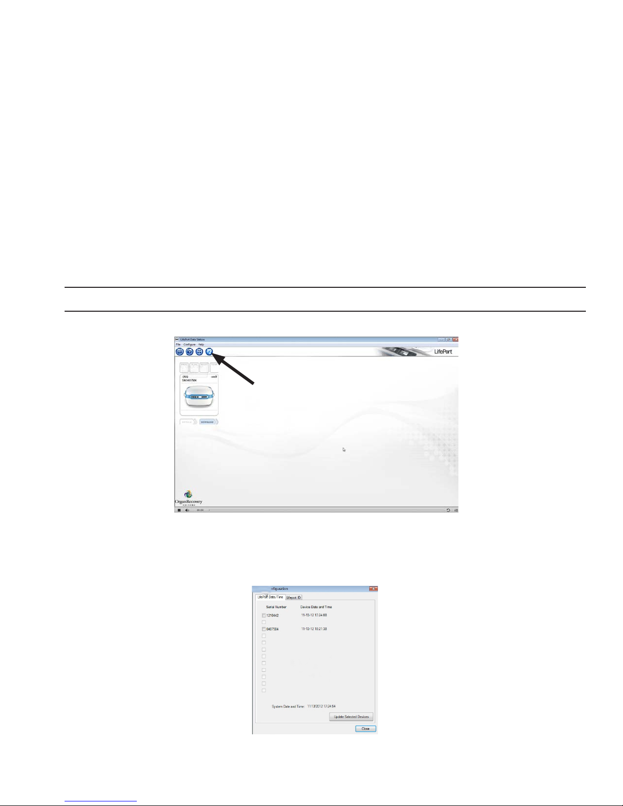
Setting up External Communications using Data Station
Data Station software allows communication between a LifePort and a computer, making it possible to
monitor LifePort operations with the computer, and any other computers networked to it.
Use instructions provided with the Data Station software to install the app on the computer(s) you plan to
use for monitoring.
Use these instructions to synchronize the LifePort with the computer’s time and date, and to create a Unit ID.
NOTE: This procedure can only be performed with a LifePort that is not currently streaming data to a computer .
1. Connect the LifePort to the computer using the data cable.
2. Start the Data Station app on the computer.
3. Click the CONFIGURE LIFEPORT button as shown. The screen displays the LifePort Conguration
window.
4. Click on the LifePort Date/Time tab to synchronize the LifePort’s onboard clock with the Data Station
LifePort Kidney Transporter Operator’s Manual 755-00029 Rev H
20
 Loading...