

organization 3DX 450 FSE V3 Instruction Manual
3DX 450 FSE V3
COPYRIGHT ©
Instruction Manual Author: Per Backman
Date:
09/30/2006
Version 1
CONTENTS
• 2…Safety Note’s
• 3...Hardware Identification
• 4...Assembly Instructions
• 5...Maintenance
• 6 - 8...Main Rotor Assembly
• 9 - 12...Main Frame Assembly
• 13 - 15...Tail Rotor Assembly
• 17...Linkage Setup
• 18 - 20...Radio Setup
• 21...Spare Parts
• 22...Specifications

Page 2
Note’s Before Starting
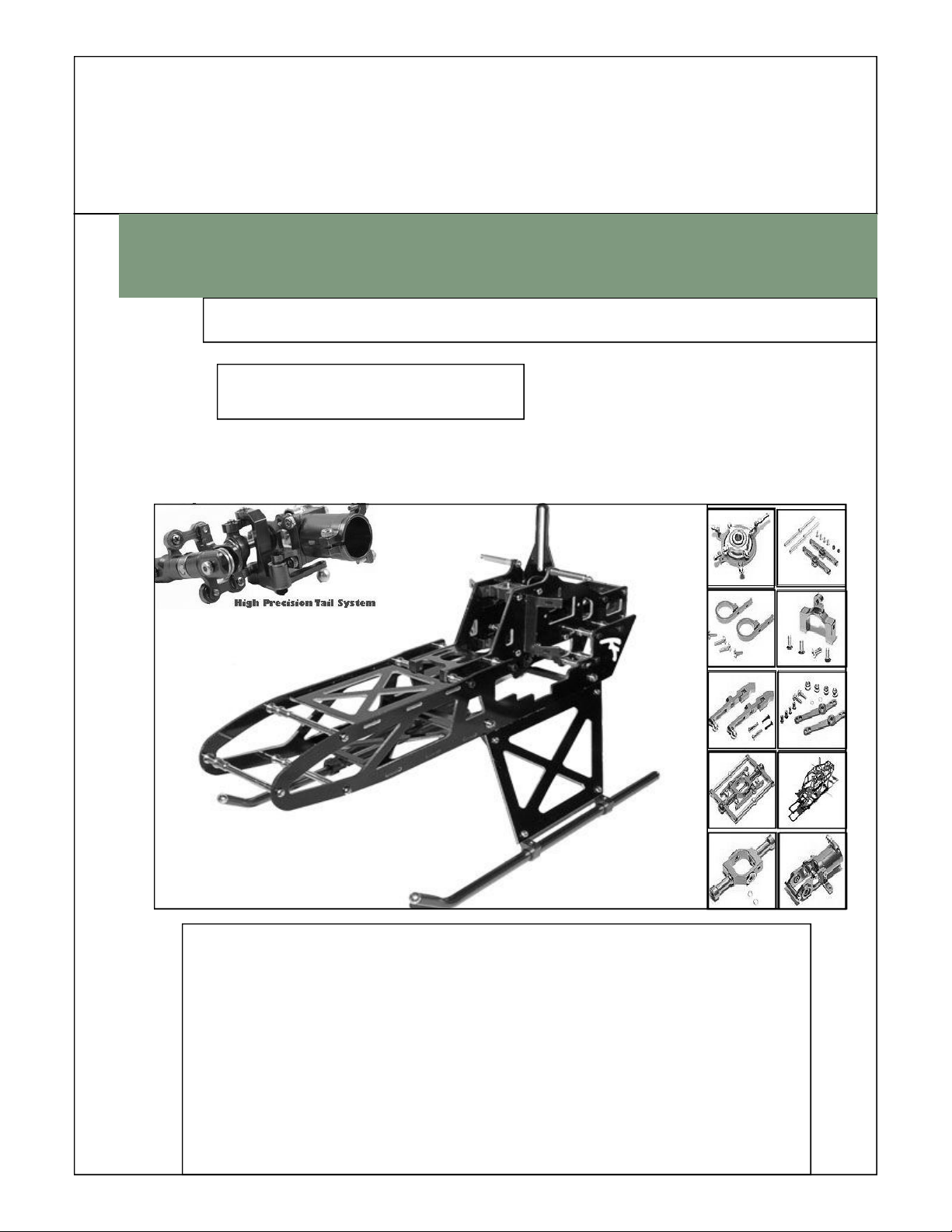
WELCOME TO 3DX450 R/C MODEL PRODUCTS
Thank you for buying this Product. The 3DX 450 FSE Helicopter is designed as easy to use, full featured
Helicopter R/C model capable of all forms of rotary flight. Please read the manual carefully before assembling the
model, and follow all precautions and recommendations located within the manual. Besure to retain the manual for
future reference, routine maintenance, and tuning.
This helicopter features the best design available on the Micro-Heli market to date, providing flying stability for beginners, full aerobic capability for advanced fliers, and unsurpassed reliability for customer support
IMPORTANT NOTES
R/C helicopters, including the 3DX 450 FSE are not toys. R/C helicopters utilize various high-tech products and
technologies to provide superior performance. The rotating blades on the model spin at high speed and can cause
potential risk or injury if used improperly. It is mandatory that you observe all RIC safety rules and adhere to local
laws as applicable. We recommend that you contact your local hobby store and inquire about safety, rules, regulations, and local laws and statutes regarding R/C model operation in your area. Please make sure to be conscious of
your own personal safety and the safety of others and your environment when operating all products.
When used properly, this R/C product will provide years of R/C entertainment. We recommend that you obtain the
assistance of an experienced pilot before attempting to fly our products for the first time. A local expert is the best
way to properly assemble, setup, and fly your model for the first time. The 3DX 450 FSE requires a certain degree
of skill to operate, and is a consumer item. Any damage or dissatisfaction as a result of accidents or modifications
are not covered by any warrantee and cannot be returned for repair or replacement. Please contact our distributors
for free technical consultation and parts at discounted rates when you experience problems during operation or
maintenance.
Note: Fly only in safe areas, away from other people. Do not operate R/C aircraft within the vicinity of homes or
crowds of people. R/C aircraft are prone to accidents, failures, and crashes due to a variety of reasons including,
lack of maintenance, pilot error, and radio interference. Pilots are responsible for their actions and damage or injury
occurring during the operation or as of a result of R/C aircraft models.
SAFTY NOTES
1. Locate an appropriate locaton:
R/C helicopters fly at high speed, thus posing a certain degree of potential danger.
Choose an appropriate flying site consisting of flat, smooth ground, a clear open field, or a large open room, such
as gymnasium or warehouse without obstacles. Do not fly near buildings, high voltage cables, or trees to ensure
the safety of yourself, others, and your model. Do not fly your model in inclement weather, such as rain, wind,
snow, or darkness.
2. Obtain the assistance of an experienced pilot:
Before turning on your model and transmitter, check to make sure no one else is operating on the same frequency.
Frequency interference can cause your model, or other models to crash. The guidance provided by an experienced
pilot will be invaluable for the assembly, tuning, trimming, and actual first flight.
(Recommend you to practice with simulated flying software.)
3. Always be aware of the rotating blades:
During the operation of the helicopter, the main rotor and tail rotor will be spinning at a high rate of speed. The
blades are capable of inflicting serious bodily injury and damage to the environment. Be conscious of your a ction s,
and careful to keep your face, eyes, hands, and loose clothing away from the blades. Always fly the model a safe
distance from yourself and others, as well as surrounding objects. Never take your eyes off the model or leave it
unattended while it is turned on. Immediately turn off the model and transmitter when you have landed the model.
Page 3
Hardware Identification
WELCOME TO 3DX450 R/C MODEL PRODUCTS
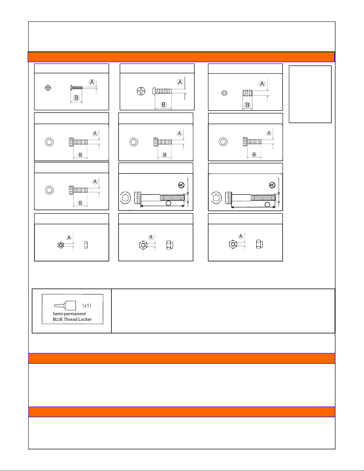
M2x7mm Philips Head Screw M2x7mm Self tapping Screw M3x3mm Set screw
M2X4mm Socket Head Screw M2x6mm Socket Head Screw M2x8mm Socket Head Screw
M2x16mm Socket Head Screw M2x18mm Socket Head Screw M3x22mm Socket Head Screw
A = Diameter
B = Length
B
M2 Hex Nut M2.5 Lock Nut M3 Lock Nut
B
Very Important!
Thread Locker Is Used To Keep Assemblies Tight As Vibration May Cause Them To become Loose
Due to the vibrations caused by operation, nuts, bolts, and set screws may have a tendency to loosen.
Repeated tightening is not the solution, instead, the careful application of thread locker is required.
Thread locker works something like a glue. There are various types of thread locker, from permanent
types which are usually RED in color, to semi-permanent types which are usually BLUE in color. BLUE
thread locker is what is recommended. Thread locker is not needed with nylon-lock nuts, nor where
metal screws thread into plastic. Finally, be careful to remove all traces of oil or grease by applying a
degreaser or acetone to bolts prior to assembly - clean with a paper towel until all traces are gone.
NOTE: Use care when using thread locker near bearing areas as contamination may ruin the bearing and
cause it to seize. Never use thread locker on metal to plastic
Tools needed for assembly
• Phillips Screw Driver • Nut Drivers (2mm/3mm/4mm) • Allen Drivers
(0.050in/1.5mm/2mm/3mm/4mm)
• Small Hammer • Lexan Scissors • Hobby Knife
•
Needle-nose Pliers • Ruler (metric) Greater Than 30cm • 4-way Wrench
Optional Tools for assembly
Dial Indicator • Ball Link Pliers • Calipers
•
• one sheet of thin typing paper • Pitch Gauge

Page 4
Assembly instruction
Assembling the Head & Tail
If the head and tail come 100 % pre-assembled. (Option)
I do recommend you go over each screw to make sure they are secured with Thread Lock , if needed unassembled the part that
is lose and use blue Thread Lock. On areas where you are exposed to ball bearings and moving parts, make sure no Thread
Lock goes on any ball bearings.
We have supplied a detailed assembly instruction if for any reason you need to take the head or tail apart
See page 6 to 8 for the Head Assembly & page 13 to 15 for the Tail Assembly
Assembling of the Frame
1. Starting on Page 9 - Upper Frame Assembly:
• Mount the eCCPM servo holder first.
• Mount the servo to the servo holder
• Continue to mount all parts on the left side first before mounting the right side.
• Make sure to use the spacers and thread lock all areas
2. Continue on Page 10 with the Upper frame:
• Mount the right side of the frame and make sure all areas have a washers and are Thread Locked.
3. Starting on page 11 Lower Frame Assembly:
• Start with putting the Main Frame landing gear brace to the frame and use a nut on the end and make sure you use
Thread Lock
• Continue with using the longer screws and Thread Lock and use a short spacer
• Start and complete one side
• The second side will be a little harder but be patient
4. Starting on page 12 Main Gear Assembly:
• Make sure the Main shaft and Head are secure see page 4 part 25 and that is Thread Locked.
• Make sure the small spacer 69 is on place and place the gear so the main shaft goes in
• Use the proper screw and use a nut with thread lock
• Mount a collar and use thread lock on the lock screws
Assembling the Head, tail & boom & linkage’s
1. Starting on page 13 - Boom/Tail assembly:
• Use a tie-wrap on the end of the belt
• Put the belt through the boom and secure the tail assembly to the boom
• Mount the boom to the frame, and place the belt over tail drive gear.
• Turn the gear clockwise and make sure tail is turning counter clockwise, if not turn the belt 180 degrees and try
again, then stretch the belt and secure the boom.
• Assemble all parts on page 13 –15 and make sure all metal to metal areas are thread locked properly.
2. Starting on page 16 - Canopy assembly:
• Cut the canopy out and if you like you can also cut out the window and mount the dark window glass.
3. Starting on page 17 - Linkage:
• At this stage the you have assembled the frame and you have 2 servo’s installed
• Make the O & N links.
• Make sure all 3 servos have the same style servo arms and the balls are at the same place.
• Connect the receiver to the servos and turn it on, after the servos are in neutral change the servo arms to be com-
pletely horizontal.
• Mount the arms to the swash plate and make sure the swash plate, washout arms and flybar & mixer arms and the
blade grips are all horizontal.

Page 5
Regular maintenance is required to keep the 3DX450 FSE helicopter in optimal and safe flying condition, The
model requires precise configuration of the components and settings to be kept by the owner. Maintain regular
maintenance on the model to avoid accidents or loss, and optimum performance.
Regular Maintenance instruction
Main Rotor Check List
1. Main Rotor Housing: When the main rotor housing is worn or faulty, there will be obvious vibration and poor
flight control. Check the main rotor, main shaft, and feathering shaft for wear or deformity. Replace parts as
necessary to eliminate imbalance.
2. 0-Rings: The 0-Rings will lose their elasticity over time. This will cause excess play on rotor and cause instability. Replace as needed.
3. Main Rotor Holder: When the heli will not fly or reacts sluggishly, even after checking for proper setting of
pitch and throttle, check the following items: Plastic Parts, Ball bearings, Rotor Blades.
4. Check for excess play or gaps between the surfaces, missing or broken parts, or binding or restricted movement. It is important to check for main rotor balance before each flight. Operating the model when out of balance will cause excessive wear and premature failure of parts, possibly resulting in a dangerous situation.
5. Control Arm Assembly: Check regularly for cracked, worn, bent or binding control arms and pushrods.
Smooth movement of control arms and linkages is required for stable, vibration free flight. Swashplate: Check
for excess slop in the main ball where the main shaft rides on, and slop or looseness between the plastic and
metal surfaces. Swashplate wear will result in poor stability and lack of control during flight. Replace as necessary.
Fuselage/Chassis
1. Main Shaft Bearing: Normal replacement interval for proper operation is between 60-100 flights. If flying 30 or
extreme aerobatics often, inspect the bearing more frequently and shorten the interval as necessary.
2. 0ne-way Bearing: One-way bearings have longer lifetimes. Failure is not commo n. To keep the one-way bearing in good operation, remove it to clean and lubricate after every 50 flights. If the main drive gear is loose, you
should replace the one-way bearing.
3. Drive Belt: We are using only top quality, stretch-proof belts. it is however, impossible to prevent the belt from
stretching or wearing out, Check belt tension regularly, and check for the wear on the teeth. Replace as necessary.
Tail Rotor System
During assembly, take special care to keep the connecting parts in smooth operation, and avoid excess play or
binding. Failure to do so will result in poor Right stability. The linkage rods and ends will break and wear due to normal usage, crashing, and poor maintenance and environment. Check for wear and proper op eration regularly, replace as needed.
Linkage Rods & Connection Parts
1. Tail Rotor Control Set: Check the tail rotor bearing regularly. If there is excess play or gaps replace immedi-
ately. Avoid any binding or improper contact on the tail components and bearings as this will cause excess
wear and heat, potentially melting or deforming the tail system.
2. Tail Unit Assembly: Avoid flying in tall grass or weeds, If grass or weed becomes lodged in the tail rotor unit, it
will interfere with the operation, and cause the helicopter to lose control. Always check for foreign objects in the
tail and clean them off immediately. Avoid using lubricants on the exposed surfaces of the model as it will attract and collect dirt and debris, and cause failure.
3. Tail Rotor Housing: Disassemble Tail rotor housing for cleaning and maintenance after every 50 flights. If the
tail does not operate smoothly or shows any signs of stress or wear, please replace immediately.
4. Tail Rotor: Check the Tail Rotor blades regularly for damage, especially if the helicopter ever strikes the
ground while flying, or after hard landings. Damaged Tail Rotor blades can induce vibration.
NOTICE: Maintain regular maintenance on model to avoid accidents or loss.
Page 6
Main Head Installation
MAIN ROTOR INSTALLATION
Each section of the manual has its associated parts bag. Each bag is labeled accordingly. Make sure to only o pen the bags as
indicated in the instructed manual and place them into the provided parts cases. Do not open all the b ag s at once, or out of order to avoid confusion and difficulty assembling the model.
Start assembling the model by beginning with the main rotor head. We will build the model from the rotor head, out to the rest of
the model. Apply silicon lubricant in the inside and outer edges of the o-rings, then insert them into the main rotor head. The
flybar ends must be the same length on each side of the rotor head. Measure the distance between the edge of the flybar paddle and the flybar control arm; make this distance the same on both sides. The flybar control arms must be parallel to each
other.
The flybar paddles must be locked in the same position, exactly horizontally level with the swash plate. Use an angle of attack
ruler on each flybar paddle and adjust the angles so that they are the same, and have the correct angle. It may become necessary to apply some glue on the screws to properly tighten them. The screws must be tightened snugly, but be careful to not over
tighten them as it will strip the threads and cause the assembly to become loose.
Note: After tightening the flybar control arms and paddles, check for free movement and minimal gaps between the surfaces. All
rotor head assemblies should be assembled tightly snug, without any binding or slow movement.
Note: The head and Tail assembly is already pre-built from the factory
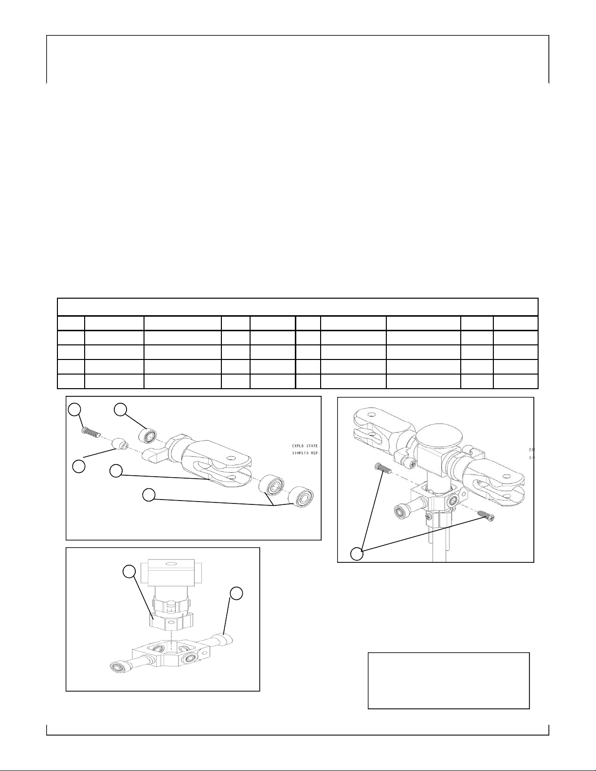
Parts for Rotor head
No Parts No. Description qty Spec No Parts No. Description qty Spec
1 UGT02A Rotor Housing 1 5 UGT01 Cross screw 2 M2x7
2 UGT01 Rotor Holder 2 6 UGT01 Bearing 2 2x6x2.5
3 UGT01 Bearing 4 3x8x4mm 7
4 UGT01 BLink ball 2 4.75mm 8 UGT07 Screw 2 2x7mm
UGT07 Seesaw Holder 1
4
6 5
2
3
8
1
7
Use Thread Lock on all metal to metal
area’s.
Use oil on all bearings
Main Head Installation
Page 7
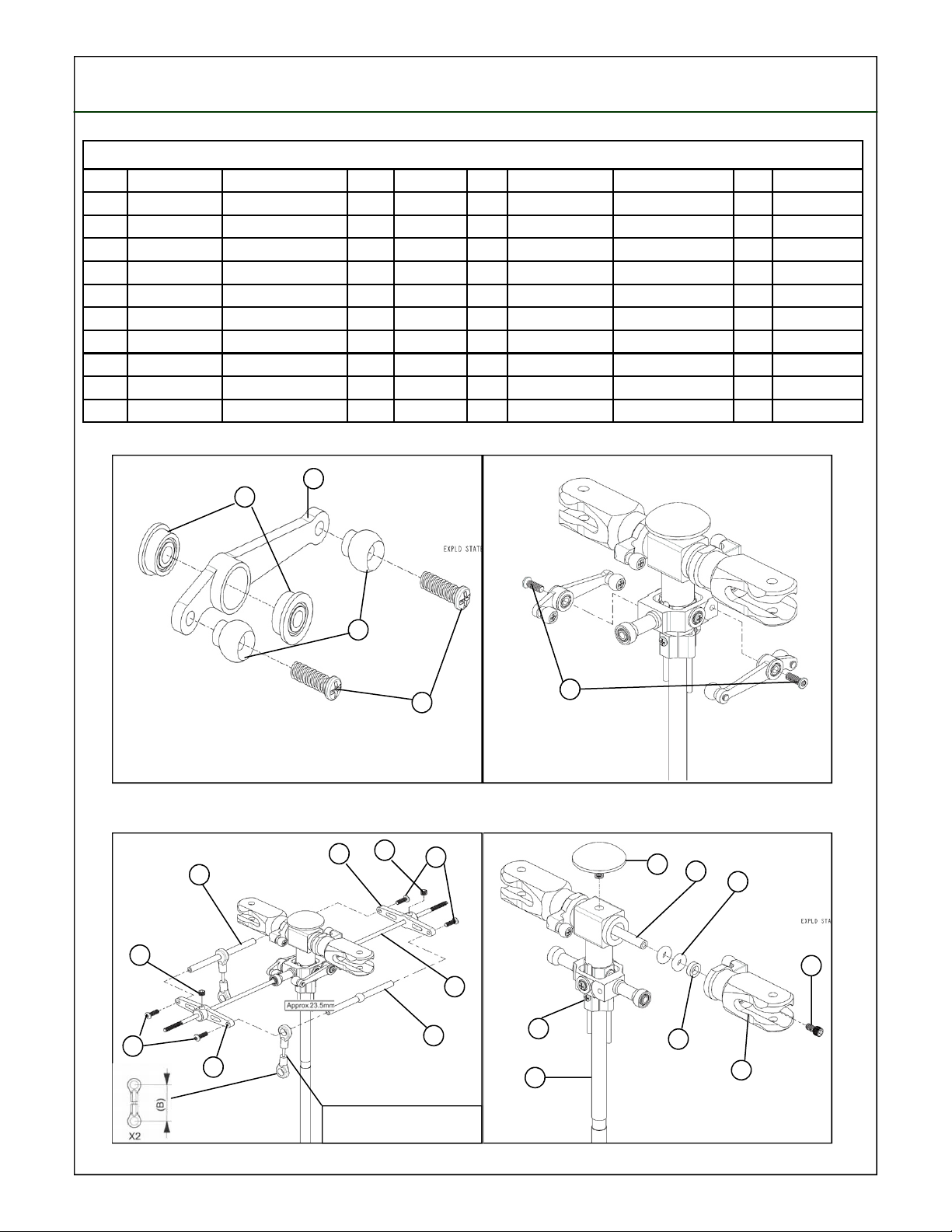
Parts for Rotor head
No Parts No. Description qty Spec No Parts No. Description qty Spec
9 UGT08 FlangeBearing 4 2x5x2.mm 19 UGT02B Housing Hat 1
10 UGT08 SF Mixer Lever arm 2 20 UGT01 Feathering Shaft 1 M3x42mm
11 UGT08 Linkage Ball 4 4.75MM 21 UGT02 O-ring 2 3x6.5x4mm
12 UGT08 Cross Screw 4 M2x7mm 22 UGT01 Collar 2 M3x5.2.5mm
13 UGT08 Socket Head Screw 2 M2x8mm 23 UGT01 Rotor Holder 2
14 UGT03-A Control Rod 2 24 UGT01 SocketHeadScrew 2 M2x6mm
15 UGT03-B Control Arm 2 25 UGT02 Socket Screw & Nut 1Set M2x16 M2x12 M2mm
16 UGT03 Set Screw 2 M3x3mm 26 UGT02 Main Shaft 1 M5x116mm
17 UGT03 Socket Head Screw 4 M2x6mm
18 UGTS02 Flybar 1
10
9
16
17
11
13
25
26
19
20
21
24
22
23
12
16
14
15
17
18
14
14
15
Assemble Linkage rod (B) before
Assembling flybar control set
 Loading...