

orfit SAGITTILT 32070/900 Instruction Manual
Page 1 of 8
INSTRUCTIONS FOR USE
SAGITTILTTM PRONE
BREAST SOLUTION
STORAGE CART
Article No. : 32070/900
A. GENERAL PRODUCT INFORMATION
The product referred to in this document is a
storage system for medical devices, used for
patient positioning and immobilisation in radiation
therapy.
This product may only be used in combination with
Orfit immobilisation products. Orfit prohibits the
use of unauthorised third-party products in
conjunction with its own products.
B. PRODUCT DESCRIPTION
This storage cart is used to store the SagittiltTM
Prone Breast Solution in an upright position.
Information on these other parts (and instructions
on how to make the masks) can be found in the
respective ‘instructions for use’ and on
www.orfit.com.
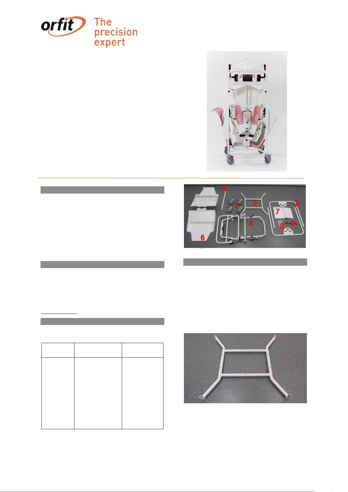
C. PARTS LIST
The storage cart contains the following parts:
ART. NO.
DESCRIPTION
PART(see
picture below)
32070/900
containing:
4 wheels
2 vertical frames
1 bottom frame
1pivoting
mechanism
1 centre axis
2 side pockets
1 storage tray
1 bag of screws
1 set of tools
1
2
3
4
5
6
7
8
9
Figure 1
D. INSTALLATION
STEP 1: Packaging
Unpack all the items and verify if you have all the
necessary products described in the parts list in the
previous paragraph.
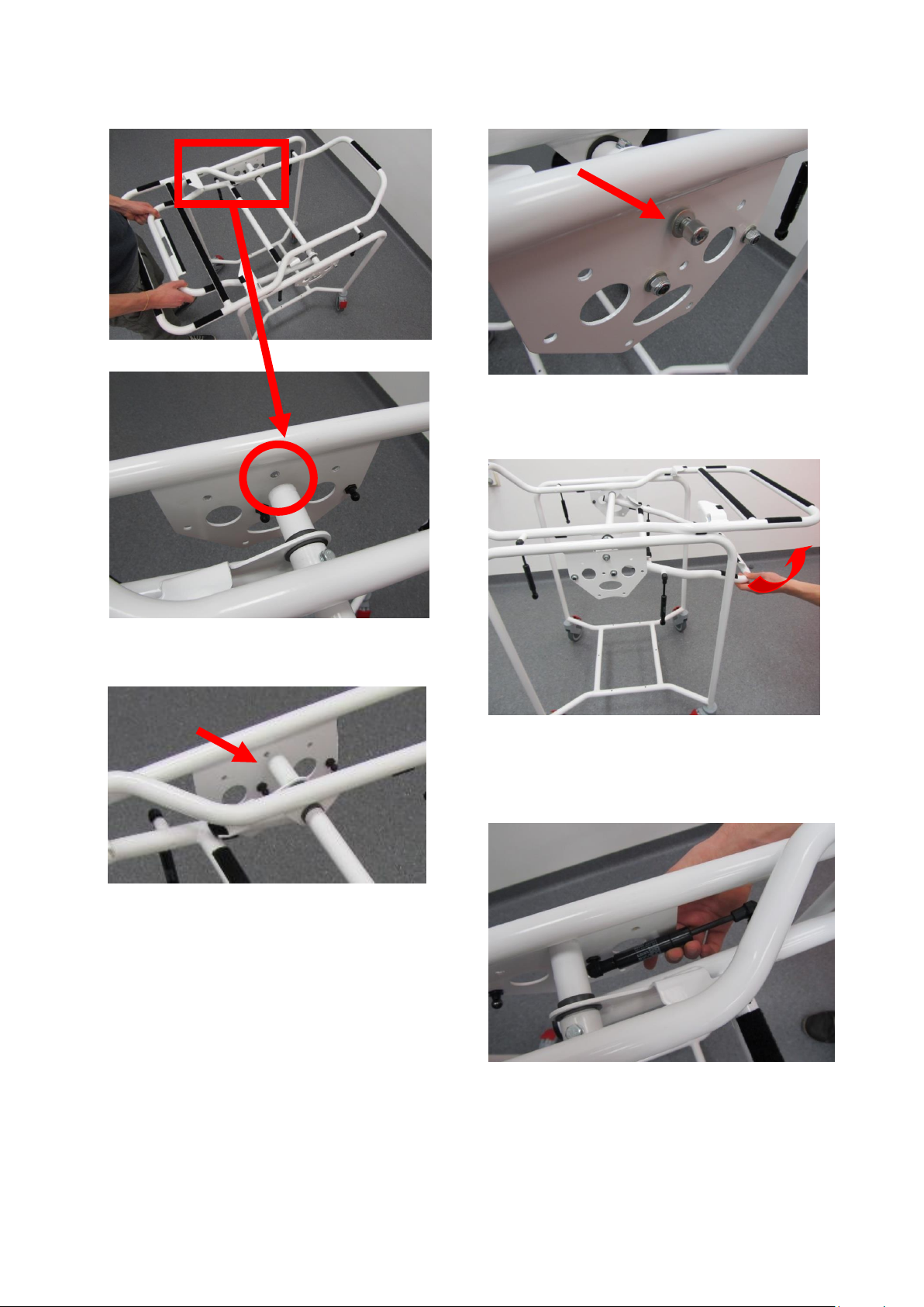
STEP 2: Mounting of vertical frames
Attach the 2 vertical frames to the bottom frame.
Make sure the black buttons are facing inwards,
towards each other.
Figure 2

Page 2 of 8
Figure 3
STEP 3: Mounting of the wheels
Turn the structure upside down so the device is
resting on the vertical frames and the bottom frame
is facing upwards.
Figure 4
Now attach the 4 wheels to the bottom frame and
tighten the screw with the wrench.
Figure 5
Once the wheels are attached, turn the whole
structure again so it is resting on the 4 wheels.
Switch on the brakes of the wheels.
Figure 6
STEP 4: Mounting of the pivoting mechanism
Take both screws out of the center axis of the
pivoting mechanism with the use of an Allen wrench.
Figure 7
Figure 8
Insert the pivoting mechanism between the two
vertical frames. The large frame should be facing
upwards and the small one downwards. Be aware
to mount it in the correct direction by matching the
numbers on the pivoting mechanism and the
vertical frames (number 1 and 2). This should be
done by 2 persons.
Page 3 of 8
Figure 9
Attach the screw again to the center axis by
screwing it into the top hole of the vertical frames
on both sides.
Figure 10
The washer is used on the outside of the vertical
frame.
Figure 11
STEP 5: Mounting of hydraulic hinge
Place the large and small frame horizontally.
Figure 12
Push the black hydraulic hinges of the short frame
onto the black buttons on the vertical frames.
Match the numbers on the hinges with the ones on
the frame (number 3 and 4).
Figure 13
 Loading...