

Page 1
3651 N Highway 89 • Chino Valley, AZ 86323
(928) 636-7080 •www.orfab.com
JEEP TJ, YJ, & UNLIMITED (TJL)
SWING-A-WAY TIRE CARRIER
SWING-A-WAY TIRE/CAN CARRIER
1987-95 YJ Kits # 85095, 86095
1997-2006 TJ & TJL Kits # 85201, 86201
Before starting installation
WARNING
The load rating for these tire-can/tire carriers is a
MAXIMUM of 175 lbs . Please be aware that some tire
and wheel combinations along with gas cans and hi-lift
jacks can
exceeds don’t mount hi-lift jack to carrier.
WARNING
Some states require a center high-mount stop lamp by
law. OR-FAB recommends that you consult your state
laws before you install this kit. If required, you will need
optional ORF (CHMSL) kit # 87017 .
exceed this MAXIMUM rating. If weight
WARNING
Read and understand all instructions, warnings, cautions, and notes in this sheet and in your owners manual before you begin the installation of this tire/tire-can
carrier kit.
CAUTION
Proper installation of a ORFab tire carrier kit requires
knowledge of the factory recommended procedures for
disassembly and assembly of original equipment components. We recommend that the factory shop manual
and any special tools necessary to your vehicle be on
hand during the installation. Installation of this tire carrier lift kit without proper knowledge of the factory recommended procedures may aect the performance of
these components and the safety of your vehicle. We
strongly recommend that a certied mechanic familiar
with the installation of similar components install this
tire carrier kit.
NOTE
These instructions cover TJ, YJ, and TJL models;
some images may not match your vehicle. The Tire/
Can Carrier is designed to use lip-style Gerry cans. To
carry non-lip cans, you need the optional Non-Lip Can
Carrier Adapter, Kit # 87013 .
NOTE
Kit parts are prefaced by the word kit and appear in
bold print.
1. Carefully read all warnings and instructions com pletely before beginning.
2. Verify all parts have been received in this kit by
checking the parts list at the end of this document.
3. Only inst
specied . If anytime during the installation you
encounter something dierent from what is outlined
in the instructions, call technical support at (928)
636-7080.
4. Park the vehicle on a clean, d
and block the tires so the vehicle cannot roll in either
direction.
all this kit on the vehicle for which it is
ry, at, level surface
Swing-Away Tire Carrier & Tire/Can Carrier 1 Kits 85095, -201, 86095, -201
Page 2
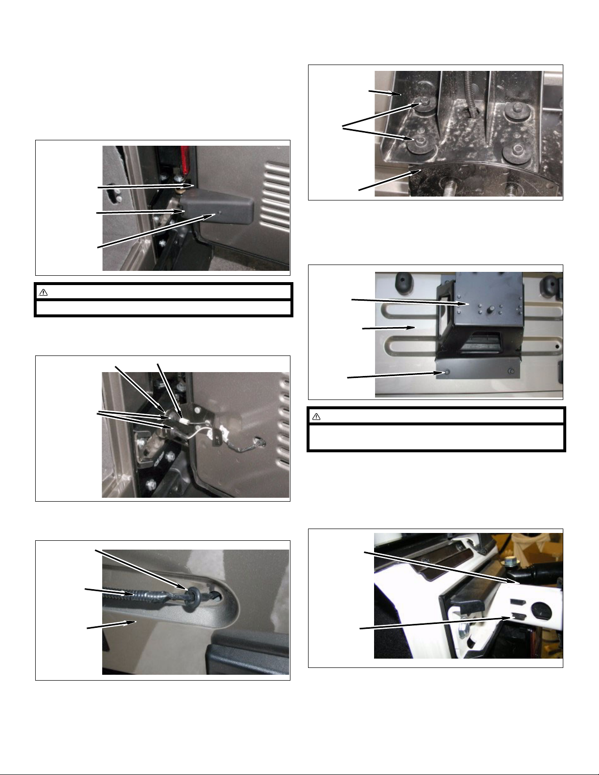
Prepare to install kit
d. Remove four bolts and center stop lamp from
spare tire bracket.
1. Remove spare tire.
2. Center stop lamp.
a. Remove screw and cover from open tailgate.
Tailgate
Cover
Screw
NOTE
Note location of taped wire before disconnecting it.
b. Disconnect center stop lamp wire connectors
from tailgate bracket.
Center
Stop Lamp
Bolt
Spare
Tire
Bracket
3. Spare tire bracket.
a. Remove four bolts and spare tire bracket from
tailgate.
Spare Tire
Bracket
Tailgate
Tailgate Bracket
Stop Lamp
Wire
Connectors
c. Remove grommet and wire harness from tail-
gate.
Grommet
Wiring
Harness
Ta il ga te
Tape
Bolt
NOTE
When installing the tire carrier kit it is helpful to remove
the vehicle top.
4. Tailgate.
a. 2004 models: Open tailgate, un-clip and
remove two upper and lower plastic covers from
tailgate hinges.
Plastic
Covers
Clip
Swing-Away Tire Carrier & Tire/Can Carrier 2 Kits 85095, -201, 86095, -201
Page 3
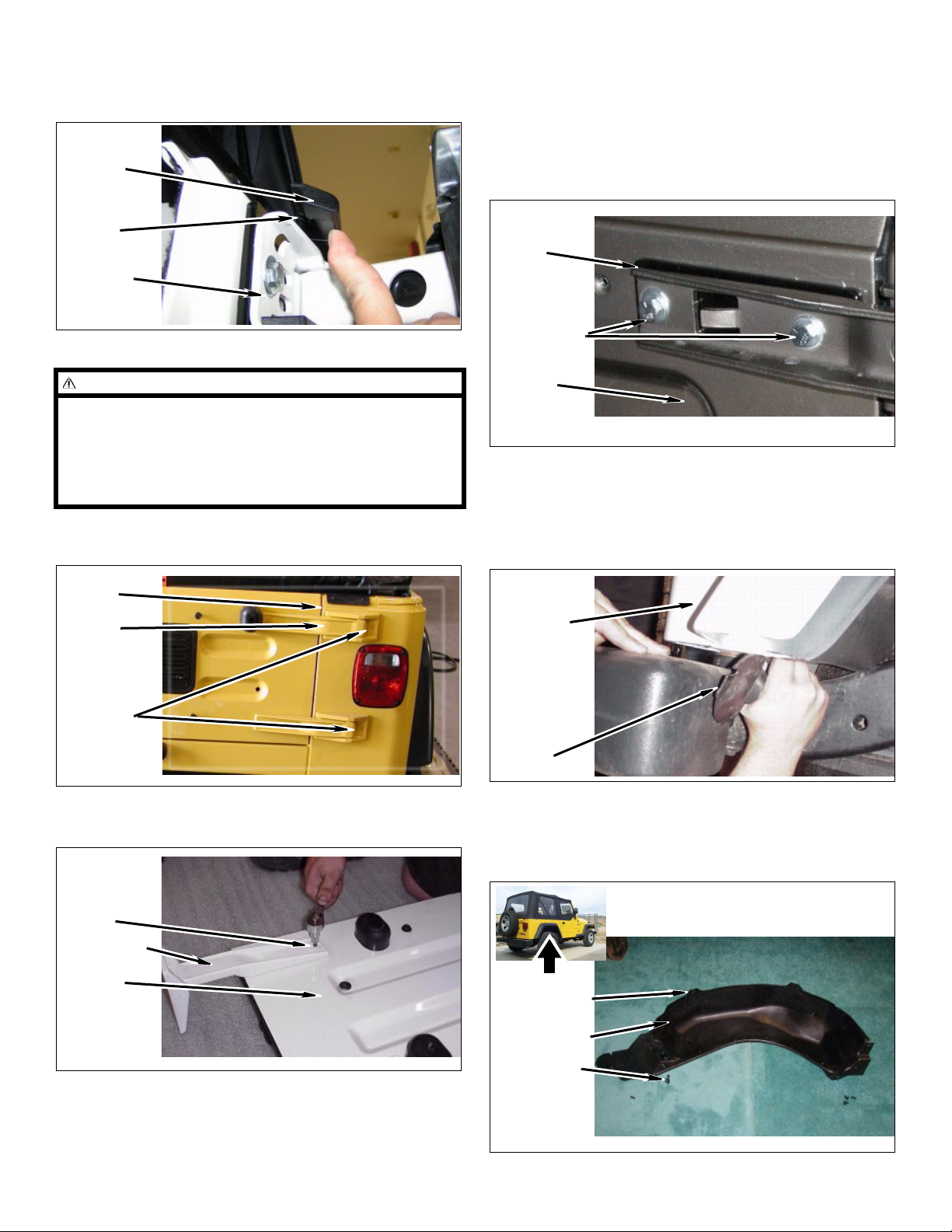
b. 2004 models: Slightly twist the upper edge and
remove two upper and lower plastic covers from
the body side of the hinges.
Plastic
Cover
Clip
Body
Hinge
e. Install two kit tailgate hinge plates and tailgate
hinges on tailgate.
Cast Aluminum Hinge:
Install four kit bolts (5/16” x 1 1/2” allen head).
Stamped Steel Hinge:
Install four kit bolts (5/16” x 1 1/4”) and four kit
washers (5/16” USS).
Kit Tailgat e
Hinge
Plates
Kit Bolts 5/16”
x 1 1/4”, Wash-
ers 5/16” USS
NOTE
In the step below a hobby knife makes a perfect cut for
separating the body paint and the hinge bolts.
2003 and older: The d
ouble nut fasteners will not be
reused.
2004-2006:
The upper captive nuts will be dealt with
later in these instructions.
c. Remove four bolts, tailgate, hinges, and two sets
ouble nut fasteners from body.
of d
Body
Hinges
Bolt
d. Position tailgate on the ground. Remove four
bolts and tailgate hinges from tailgate.
Tailgate
2004 Stamped Steel Hinges Shown
02 and older: Inner fender.
5. 20
a. Remove push clip and inner fender from the
ba
ck portion of body. Pull the inner fender out
from under rear quarter panel as shown.
Rear Quarter Panel
Push Clip
And Inner
Fender
6. 20
03-2006: Inner fender and air canister.
a. Remove seven push clips, two locator tabs, and
r liner from passenger side rear wheel well.
fende
Bolt
Hinges
Ta il ga t e
Locator Tabs
Fender Liner
Push Clips
Swing-Away Tire Carrier & Tire/Can Carrier 3 Kits 8509
5, -201, 86095, -201
Page 4
WARNING
Use extreme caution when working near fuel lines and
fuel tank to avoid an explosion or fire resulting in serious personal injury and property damage.
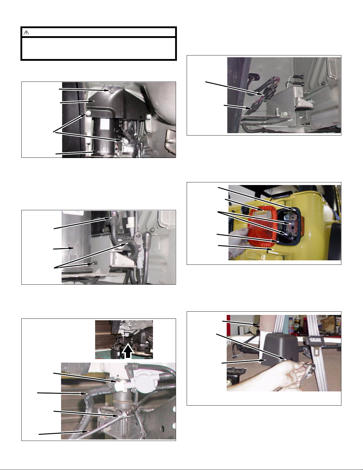
7. Passenger taillight assembly.
a. Disconnect taillight wiring harness clip from tail-
light wiring ha
rness.
b. Remove four bolts, one nut, and cover plate
from body and air canister assembly.
Nut
Cover Plate
Bolts
Air Canister
Assembly
c. Remove two wiring harness push clips and wir-
ing harness from body and air canister assembly.
d. Disconnect wiring harness connector from air
nister assembly.
ca
Wiring
Harness
Connector
Air Canister
Assembly
Wiring
Harness
Clip
Taillight Wiring Harness
b. Remove four screws and taillight lens from tail-
light assembly.
c. Remove four screws and taillight assembly from
body.
Screws
Taillight Lens
Screws
Taillight
Assembly
Body
Push Clips
e. Carefully slide a small and large clip outward
and remove a small and large vent line from air
canister assembly and vehicle.
Air Canister Assembly
Shown Removed For
Clarity
Large Clip
Large Vent
Line
Small Clip
Small Vent
Line
8. Rear seat belts.
a. Remove two torx bolts and two seat belt retrac-
tors fr
om sport bar driver and passenger side.
T50 torx used here.
Sport Bar
Tor x Bo l t
Seat Belt
Retractor
b. Lift and push carpet from wheel well, cargo area,
and sport bar toward back seat.
Swing-Away Tire Carrier & Tire/Can Carrier 4 Kits 85095
, -201, 86095, -201
Page 5
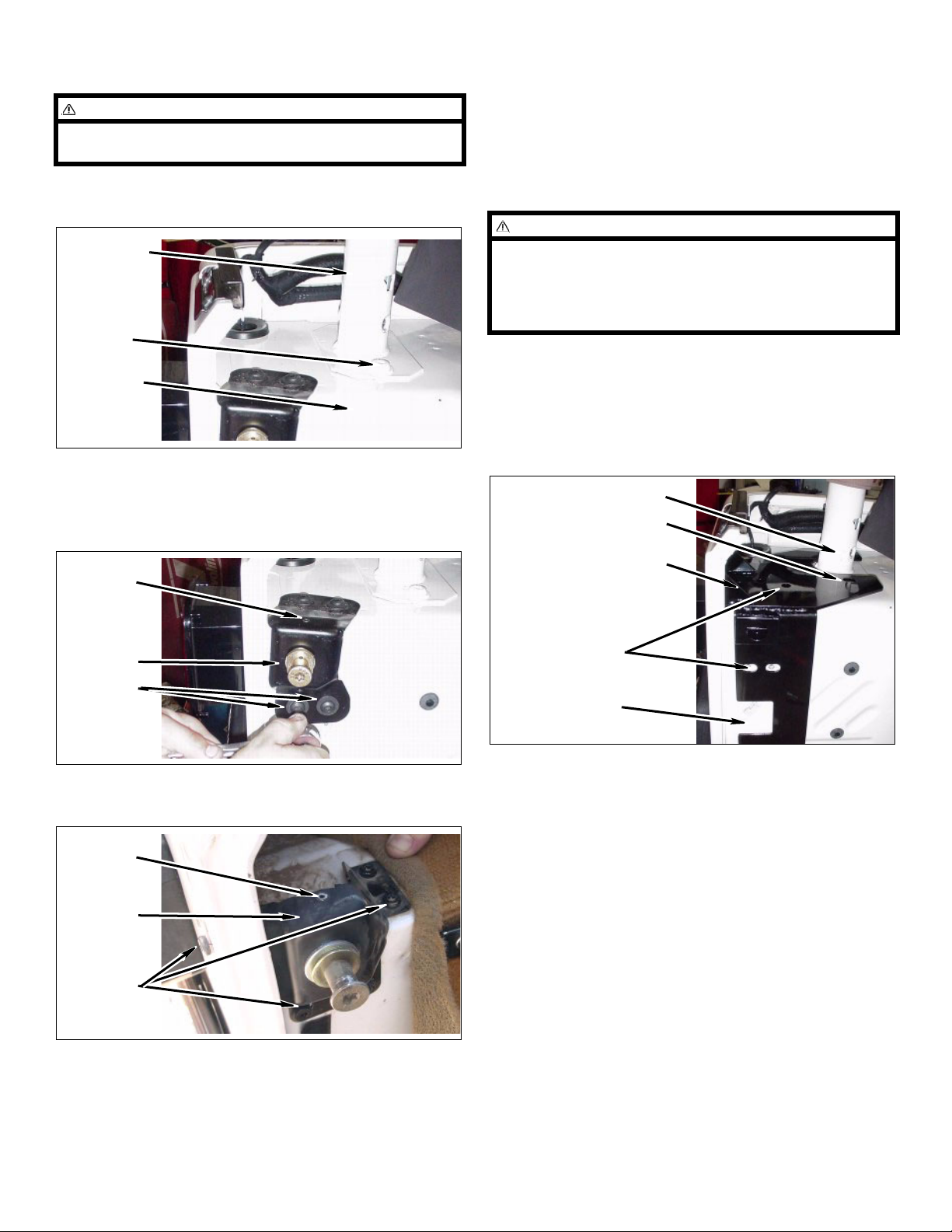
9. Sport bar rear mounts.
Install the kit
NOTE
A hobby knife makes a perfect cut for separating the
body paint and the hinge bolts.
a. Remove four T45 torx bolts from sport bar rear
mount
s and body.
Sport Bar
T45 Torx
Bolts
Body
10. Tailgate striker assembly.
a. TJ Only: R
assembly from body.
emove four bolts and tailgate striker
1. Kit reinforcement bracket driver side.
a. Position kit driver
on body, around and on top of sport bar.
WARNING
Ensure kit reinforcement brackets are snug up against
back body wall. It may be necessary to trim body putty
and excessive paint from the corners of body joints.
Ensure that the sport bar is not propping up the kit reinforcement brackets.
b. Install kit driver side reinforcement bracket
and sport bar on body with two T45 torx bolts.
Do not tighten.
c. Install kit driver side reinforcement bracket on
body with four torx bolts.
Sport Bar
T45 Torx Bolts
side reinforcement bracket
Rivet
Tailgate
Striker
Assembly
Bolts
b. YJ Only: Remove five bolts and tailgate striker
assembly from body.
Rivet
Tailgate
Striker
Assembly
Bolts
Kit Driver Side Rein-
forcement Bracket
Tor x Bo l ts
Body
d. Using kit driver side reinforcement bracket as
a template, mark the back body wall with center
punch as shown.
c. All Models: Drill rivet, and remove striker post,
shims, and flat nut from tailgate striker bracket.
Swing-Away Tire Carrier & Tire/Can Carrier 5 Kits 85095, -201, 86095, -201
Page 6
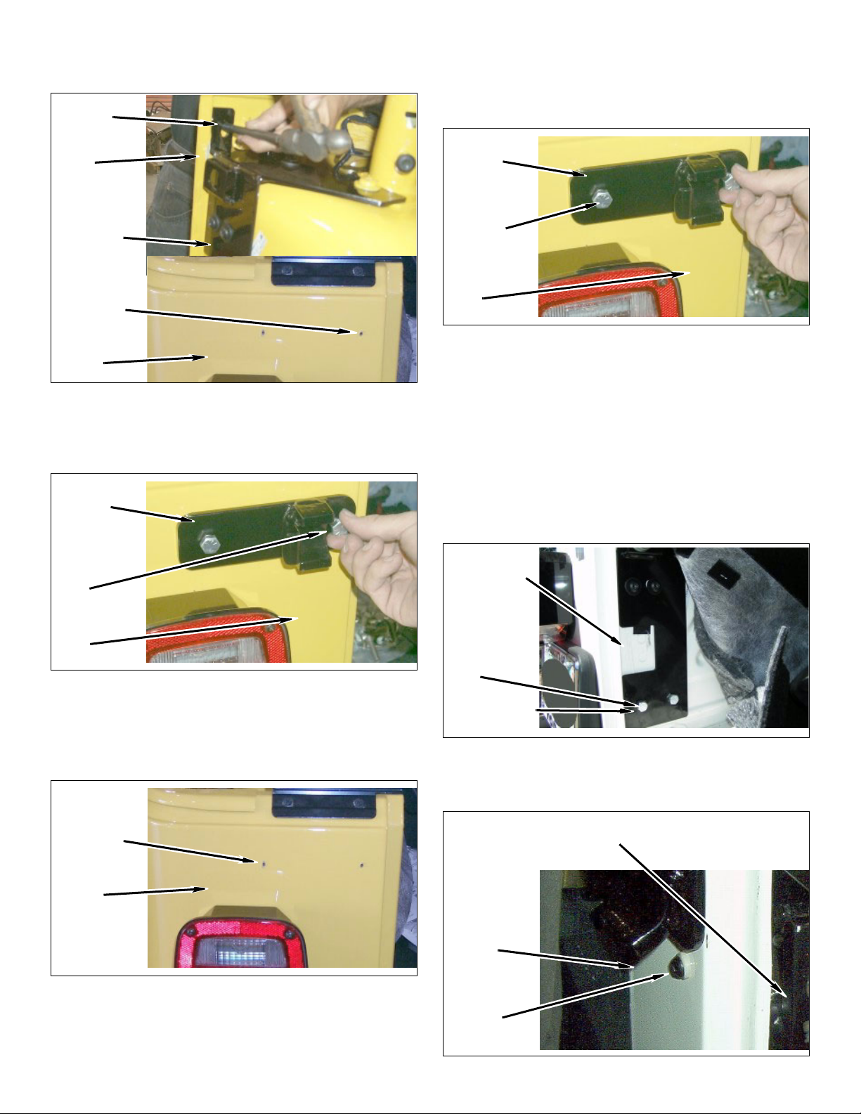
e. Drill a 1/8” pilot hole where marked. Enlarge pilot
hole with 7/16” drill bit.
Mark
i. Install kit striker plate on back body wall and kit
reinforcement bracket with a kit bolt (3/8” x 1”)
and a kit flange nut (3/8”). Tighten six torx bolts
and two kit bolts (3/8” x 1”).
Back Body
Wall
Kit Driver
Side Reinforcement
Bracket
Pilot Hole
Back Body
Wall
f. Install kit striker plate on back body wall and kit
reinforcement bracket with a kit bolt (3/8” x 1”)
and a kit flange nut (3/8”). Snug bolt but do not
tighten.
Kit Striker
Plate
Kit Bolt 3/8”
x 1”, Kit
Flange Nut
3/8”
Kit Striker
Plate
Kit Bolt 3/8” x
1”, Kit Flange
Nut 3/8”
Back Body
Wall
j. Using kit driver side reinforcement bracket as
a template, mark the wheel well with center
punch as shown.
k. Drill 1/8” pilot holes where marked. Enlarge pilot
holes with 7/16” drill bit.
l. Install kit driver side reinforcement bracket on
wheel well with two kit bolts (3/8” x 1”) and two
kit flange nuts (3/8”). Snug bolt but do not
tighten.
Wheel Well
Back Body
Wall
g. Using kit striker plate as a template mark the
back body wall with center punch as shown.
h. Drill a 1/8” pilot hole where marked. Enlarge pilot
hole with 7/16” drill bit.
Pilot Hole
Back Body
Wall
Kit Bolts 3/8”
x 1”, Kit
Flange Nuts
3/8”
Mark and Drill
m. YJ ONLY: Install kit driver side reinforcement
bracket on body with kit bolt (1/4” x 1”) and
square nut (1/4”).
Kit Driver Side
Reinforcement Bracket
Body
Kit Bolt 1/4” x
1”, Square
Nut 1/4”
Swing-Away Tire Carrier & Tire/Can Carrier 6 Kits 85095, -201, 86095, -201
Page 7
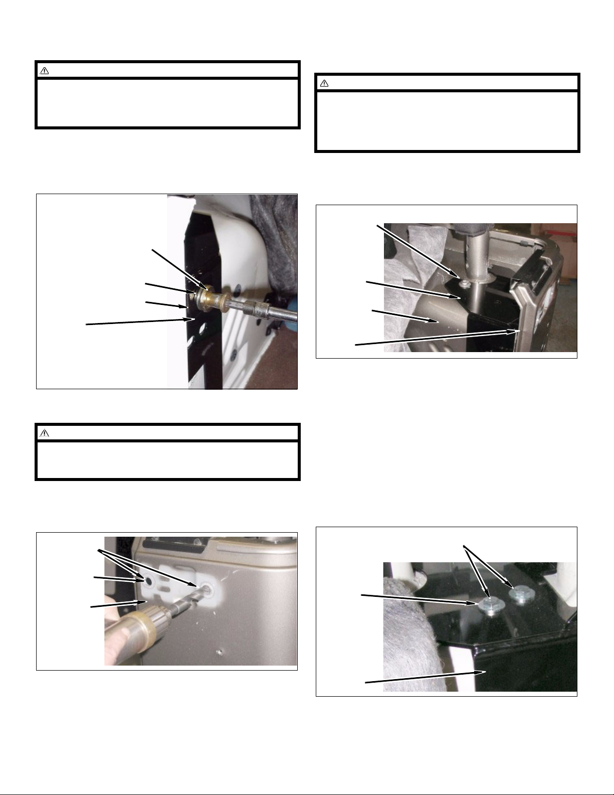
2. Tailgate striker post.
NOTE
In the step below there is adjustment for the striker
post with the factory shims. You may want to adjust the
factory shims for the desired result when the tailgate is
fully installed.
a. Position the flat nut on kit driver side reinforce-
me
nt bracket. Install striker post and shims on
kit driver side reinforcement bracket with the
flat nut.
b. Position kit passenger side reinforcement
bracket on body.
WARNING
Ensure kit reinforcement brackets are snug up against
back body wall. It may be necessary to trim body putty
and excessive paint from the corners of body joints.
Ensure that the sport bar is not propping up the kit reinforcement brackets.
c. Install kit passenger side reinforcement
bracket and sport bar on body with two torx
bolts. Do not tighten.
T45 Torx
Bolts
Striker Post
Kit Driver
Side Rein-
Shims
Flat Nut
forcement
Bracket
3. Kit reinforcement bracket passenger side.
NOTE
2004 Models: It is best to drill out the two top captive
nuts with a gradual progression of larger bits until the
two top nuts are removed.
a. 200
4 Models: Drill out two top captive nuts from
upper body/hinge area only. The final drill bit
size should be 5/8”.
Captive Nuts
Kit Pass.
Side Reinforcement
Bracket
Body
Back Body
Wall
d. Using kit passenger side reinforcement
bracket as a template, mark the wheel well with
center punch.
e. Drill 1/8” pilot holes where marked. Enlarge pilot
holes with 7/16” drill bit.
f. Install kit passenger side reinforcement
bracket on wheel well with two kit bolts (3/8” x
1”), two kit washers (3/8 USS), and two kit
flange nuts (3/8”). Snug two kit bolts and two
torx bolts but do not tighten.
Kit Bolts 3/8” x 1”, Kit Washers
3/8 USS, Kit Flange Nuts 3/8”
Drill
Drill
Body
Kit Pass.
Side Reinforcement
Bracket
Swing-Away Tire Carrier & Tire/Can Carrier 7 Kits 85095, -201, 86095, -201
Page 8
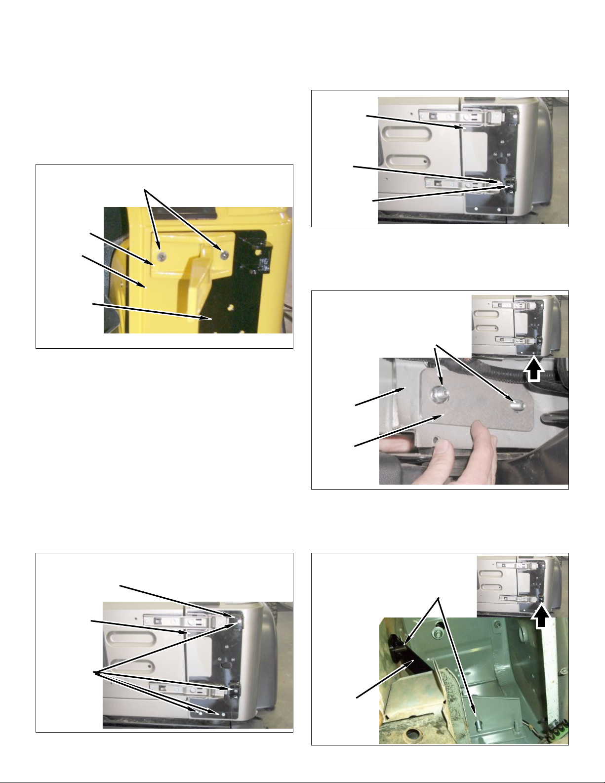
g. Position kit hinge bracket, tailgate, and hinges
on body at the same time. Snug but do not
tighten bolts at this time.
Cast Aluminum Hinge:
Install four kit bolts (5/16” x 1 1/2” allen head)
and four kit nuts (5/16” flange).
Stamped Steel Hinge:
Install four kit bolts (5/16” x 1 1/4”), four kit
washers (5/16” USS) and two kit nuts (5/16”
flange).
Kit Bolts 5/16” x 1 1/2”, Two Kit
Flange Nuts 5/16”
l. TJ Models: Install kit hinge bracket on body
with a kit bolt (3/8” x 1”), kit thick washer (1/2”),
and a kit flange nut (3/8”). Snug but do not
tighten bolts at this time.
Kit Hinge
Bracket
Kit Bolt 3/8” x
1”, kit Flange
Nut 3/8”
Kit Thick
Washer 1/2”
Hinge
Body
Kit Hinge
Bracket
Tailgate Not Shown Attached For Clarity.
h. Adjust tailgate, striker post, and hinges to align
tailgate and provide smooth operation. Snug but
do not tighten bolts at this time
i. Using kit hinge bracket as a template, mark
body with center punch in four places as shown.
j. Drill four 1/8” pilot holes where marked. Enlarge
pilot holes with 7/16” drill bit. On the bottom two
holes drill through body cross member.
k. Install kit hinge bracket on body and kit pas-
senger side reinforcement bracket with a kit
bolt (3/8” x 1”) and a kit flange nut (3/8”). Do not
tighten.
m. TJ Models: Install kit hinge bracket and kit
small bracket on body with two kit bolts (3/8” x
4”) and two kit flange nuts (3/8”). Snug but do
not tighten bolts at this time.
Two Kit Bolts 3/8” x 4”,
Two Kit Flange Nuts 3/8”
Body
Kit Small
Bracket
n. YJ Models: Install kit lower support bracket on
body and kit hinge bracket with two kit bolts
(3/8” x 1”) and two kit flange nuts (3/8”). Do not
tighten.
Kit Bolt 3/8” x
1”, kit Flange
Nut 3/8”
Kit Hinge
Bracket
Mark & Drill
Swing-Away Tire Carrier & Tire/Can Carrier 8 Kits 85095, -201, 86095, -201
Two Kit Bolts 3/8” x 1”,
Two Kit Flange Nuts 3/8”
Kit Lower
Support
Bracket
Page 9
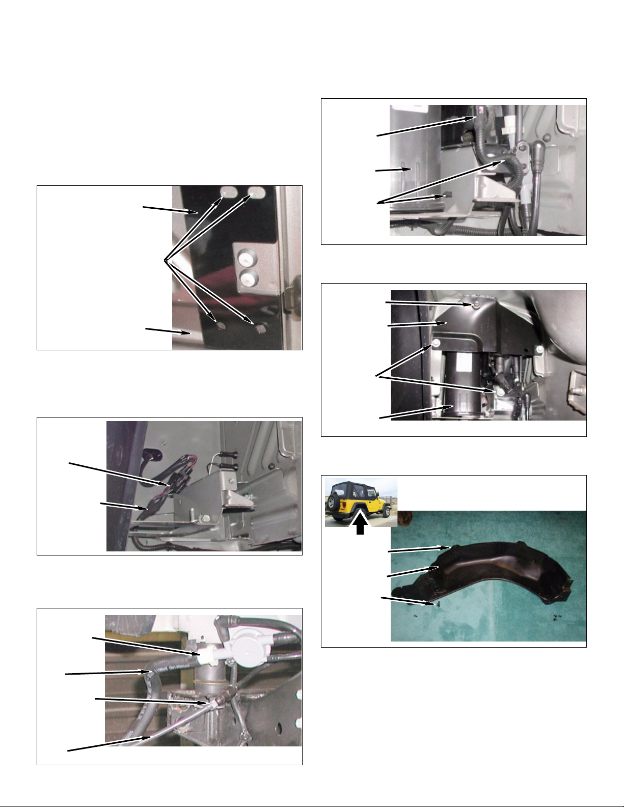
o. Using kit passenger side reinforcement
bracket as a template, mark wheel well with
center punch as shown.
p. Drill four 1/8” pilot holes where marked. Enlarge
pilot holes with 7/16” drill bit.
q. Install kit passenger side reinforcement
bracket on wheel well with four kit bolts (3/8” x
1”), two kit washers (3/8 USS), and four kit
flange nuts (3/8”).
c. Install two wiring harness push clips and wiring
rness on body and air canister assembly.
ha
d. Connect wiring harness connector on air canis-
ter assembly.
Wiring
Harness
Connector
Air Canister
Assembly
Kit Pass. Side Rein-
forcement Bracket
Mark & Drill
Two Kit Bolts 3/8” x 1”,
Two Kit Flange Nuts 3/8”
Wheel Well
4. 200
3-2006: Inner fender and air canister.
a. Connect taillight wiring harness clip
wiring harness.
Wiring
Harness
Clip
Push Clips
e. Install cover plate on body and air canister
assembly with four bolts and one nut.
Nut
Cover Plate
Bolts
on taillight
Air Canister
Assembly
f. Install fender liner on passenger side rear wheel
well with seven push clips and two locator tabs.
Taillight Wiring Harness
Locator Tabs
b. Position the air canister assembly on the vehicle.
Carefully install a small clip and a large clip on
the small vent line and the large vent line.
Large Clip
Large Vent
Line
Small Clip
Small Vent
Line
Swing-Away Tire Carrier & Tire/Can Carrier 9 Kits 85095, -201, 86095, -201
Fender Liner
Push Clips
Page 10
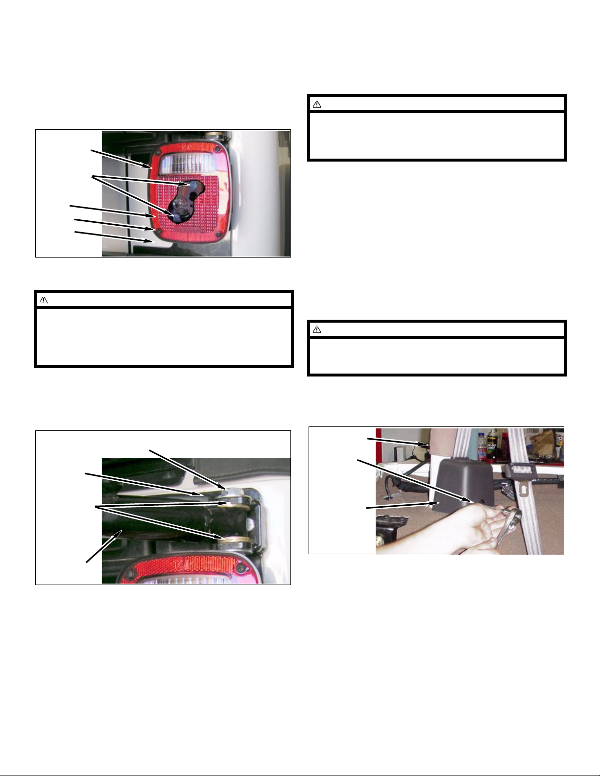
g. Passenger taillight assembly.
Finish the installation
h. Install taillight assembly on body with four kit
bolts (#12 x 3/4”).
i. Install taillight lens on taillight assembly with four
screws.
Taillight
Assembly
Kit Bolts
#12 x 3/4”
Taillight
Lens
Screws
Body
5. Tire carrier.
CAUTION
In the step below you may need to slightly modify the
length of the upper kit 1/2” x 2 3/4” bolt so that it will not
hit the top of the taillight housing. The brass washers
are positioned one above and two below the kit tire carrier legs.
a. Install kit tire carrier on kit hinge bracket with
two kit bolts (1/2” x 2 3/4”), six kit washers (1/2”
brass), four kit washers (1/2” USS), and two kit
nuts (1/2” locking). Do not tighten.
1. Adjust kit tire carrier.
NOTE
In the step below it may be necessary, depending on
your wheel and tire combination, to slightly align the
tire carrier so that it hits above the striker plate cup.
This is to allow for tire weight and tire carrier flex.
a. Align the kit tire carrier w
Check to see if kit tire carrier closes and alignment is correct. If the alignment is not correct
loosen and adjust the kit hinge plate. Once
alignment is achieved tighten hinge bolts, tailgate bolts, and kit bracket bolts.
2. Rear seat belts.
a. Position the carpet from wheel well, cargo area,
d sport bar back to its original location.
an
NOTE
In the step below it is necessary to hold the seat belt
retractors in there installed orientation so the seat belt
will release from the seat belt retractors.
b. Install two seat belt retractors with two torx bolts
on sport bar driver and passenger side. T50 torx
used here.
ith the striker plate.
Kit Bolts 1/2” x 2 3/4”, Kit Washers 1/2” USS, Kit
Nuts 1/2” Locking
Kit Hinge
Bracket
Kit Washers
1/2” Brass
Kit Tire
Carrier
b. 2004 models: Install four upper and lower plas-
tic covers on the tailgate side of hinges.
Sport Bar
Tor x Bo l t
Seat Belt
Retractor
c. Check tailgate alignment and adjust tailgate
striker post as necessary.
Swing-Away Tire Carrier & Tire/Can Carrier 10 Kits 85095, -201, 86095, -201
Page 11
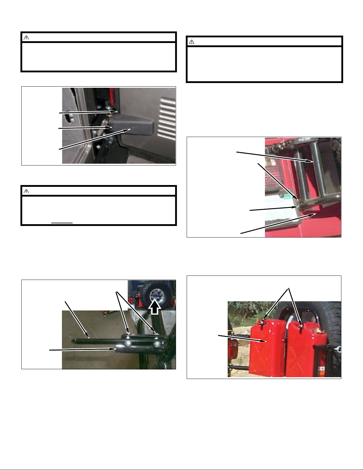
4. Kit bump-stop.
NOTE
In the step below, the third light has not been installed.
Check your local laws and or the accessories list at the
back of the instructions if you would like to install a
third light on your vehicle.
d. Install cover on open tailgate with screw.
Tailgate
Cover
Screw
3. Tire mounting.
WARNING
The load rating for these tire-can/tire carriers is a
MAXIMUM of 200lbs. Please be aware that some tire
and wheel combinations along with gas cans and hi-lift
jacks can
exceed this MAXIMUM rating.
CAUTION
In the step below you may need to slightly grind the
face of the kit lower bump-stop so that it will not dent
the tailgate. When adjusted properly the kit lower
bump-stop should just touch the tailgate and the kit 2”
x 2” stainless stick pad.
a. Install the kit lower bump-stop on the kit tire
carrier.
b. Use the location of the kit lower bump-stop on
the tire carrier to position the kit 2” x 2” stain-
less steel stick pad on the tailgate.
Kit Tire Carrier
Kit Lower Bump-stop
Kit 2” x 2” Stainless
Steel Stick Pad
a. Install kit lock ba
r on kit tire carrier with two kit
bolts (5/16” x 1”) and two kit flange nuts (5/16”).
b. Position and install tire and wheel assembly on
kit tire carrier with kit urethane spacer, kit alu-
minum plate, and kit T-bar.
Kit Bolts 5/16” x 1”
Kit Flange Nuts 5/16”
Kit Lock Bar
Kit Tire
Carrier
Ta il g at e
c. Tire-can carrier only: Install your gas cans on
tire-can carrier using the bottom lip of the cans
along with two kit threaded rods (3/8 x 8”), kit L-
brackets and kit wing nuts as shown.
Kit Threaded Rods 3/8 x 8”,
Kit L-brackets, Kit Wing Nuts 3/8”
Gas Cans
Swing-Away Tire Carrier & Tire/Can Carrier 11 Kits 8509
5, -201, 86095, -201
Page 12
Accessories
Parts list
QTY Description
The following accessories are also available:
Kit # 87013: No
Kit # 87017: TJ third light
NOTE
n-lip can carrier adapter.
kit for tire-can carrier.
Hi-lift jacks can be installed on the tire-can/tire carriers
with the use of two bolts (3/8” x 1 1/2”) not provided
with these kits.
1 Pad , 2" x 2" Stainless Steel Stick
1 Plate , Alum
4 Bolt , #12
2 Bolt , 1/2”
13 Bolt , 3/8”
8 Bolt , 5
8 Bolt , 5
2 Bolt , 5/16”
1 Brac
13 Nut
6 Nut
1 Brac
1 L
2 Nut
1 Brac
1 Plate , S
2 Plates , T
1 S
1 T
8 Wa
6 Wa
4 Wa
4 W
1 T-
1 Loc
s , Flange 3/8”
s , Flange 5/16”
ower Bump-stop
s, 1/2” Locking
pacer , Urethane
ire Carrier
sher , 5/16” USS
shers , 1/2” Brass
shers , 1/2” USS
ashers, 3/8” USS
Bar
k Bar
inum
X 3/4”
x 2 3/4”
x 1"
/16” X 1 1/2” Allen Head
/16” X 1 1/4”
x 1"
ket , Driver Side Reinforcement
ket , Hinge
ket , Passenger Side Reinforcement
triker
ailgate Hinge
TJ / TJL ONLY
1 Brac
2 Bolt , 3/8”
2 Nut
2 Nut
1 Wa
YJ ONLY
1 Bolt , 1/4”
1 Nut , Squa
1 Brac
CAN CARRIER ONLY
ket , Small
x 4"
s , Flange 5/16”
s , Flange 3/8”
sher , Thick 1/2”
x 1"
re 1/4”
ket , Lower Support
2 Threaded Rods 3/8 x 8”
2 L-brackets
2 W
ing Nuts 3/8”
Rev. 07, © 2008 OR-FAB
Performance Automotive Group, Inc.
Swing-Away Tire Carrier & Tire/Can Carrier 12 Kits 85095, -201, 86 095, -201
 Loading...